

Brother HL-1070 Service Manual

© Copyright Brother 1998
All rights reserved.
No part of this publication may be reproduced in any form or by any means without permission in
writing from the publisher.
Specifications are subject to change without notice.
Trademarks:
The brother logo is a registered trademark of Brother Industries, Ltd.
Apple,the Apple Logo,and Macintosh are trademarks,registered in the United States and other
countries,and True Type is a trademark of Apple computer, Inc.
Epson is a registerd trademark and FX-80 and FX-850 are trademarks of Seiko Epson Corporation.
Hewlett Packard is a registered trademark and HP Laser Jet is a trademark of Hewlett Packard
Company.
IBM, IBM PC and Proprinter are registered trademarks of International Business Machines
Corporation.
Microsoft and MS-DOS are registered trademarks of Microsoft Corporation.
Windows is a registered trademark of Microsoft Corporation in the U.S. and other countries.

PREFACE
This service manual contains basic information required for after-sales service of the laser printer
(here- in-after referred to as "this machine" or "the printer"). This information is vital to the service
technician to maintain the high printing quality and performance of the printer.
This service manual covers the HL-1070 laser printer.
This manual consists of the following chapters:
CHAPTER I : FEATURES AND SPECIFICATIONS
Features, specifications, etc.
CHAPTER II : THEORY OF OPERATION
Basic operation of the mechanical system, the electrical system and the electrical
circuits, and their timing information.
CHAPTER III : DISASSEMBLY AND REASSEMBLY
Procedures for disassembling and reassembling the mechanical system.
CHAPTER IV : MAINTENANCE AND TROUBLESHOOTING
Reference values and adjustments, troubleshooting image defects, troubleshooting
malfunctions, etc.
APPENDICES :SERIAL NO. DESCRIPTIONS, CONNECTION DIAGRAMS, PCB CIRCUIT
DIAGRAMS.
Information in this manual is subject to change due to improvement or re-design of the product. All
relevant information in such cases will be supplied in service information bulletins (Technical
Information).
A thorough understanding of this printer, based on information in this service manual and service
information bulletins, is required for maintaining its print quality performance and for improving the
practical ability to find the cause of problems.

i
CONTENTS
CHAPTER I FEATURES AND SPECIFICATIONS............................................. I-1
1. FEATURES.........................................................................................................................I-1
2. SPECIFICATIONS ..............................................................................................................I-3
2.1 Printing...........................................................................................................................................I-3
2.2 Functions .......................................................................................................................................I-3
2.3 Electrical and Mechanical..............................................................................................................I-4
2.4 Paper Specification........................................................................................................................I-5
2.5 Print Delivery..................................................................................................................................I-6
2.6 Paper .............................................................................................................................................I-6
2.7 Effective Printing Area ...................................................................................................................I-7
3. SAFETY INFORMATION ....................................................................................................I-9
3.1 Laser Safety (110 - 120V Model only) ...........................................................................................I-9
3.2 FDA Regulations (110 - 120V Model only) ....................................................................................I-9
3.3 Caution for Laser Product (Warnhinweis für Laserdrucker).........................................................I-10
CHAPTER II THEORY OF OPERATION........................................................... II-1
1. ELECTRONICS.....................................................................................................................................II-1
1.1 General Block Diagram.................................................................................................................II-1
1.2 Main PCB Block Diagram .............................................................................................................II-2
1.3 Main PCB......................................................................................................................................II-3
1.3.1 CPU Core .......................................................................................................................II-3
1.3.2 ASIC ...............................................................................................................................II-5
1.3.3 ROM ...............................................................................................................................II-7
1.3.4 Flash Memory.................................................................................................................II-7
1.3.5 DRAM.............................................................................................................................II-8
1.3.6 Optional RAM .................................................................................................................II-9
1.3.7 Optional Serial I/O ........................................................................................................II-10
1.3.8 EEPROM......................................................................................................................II-10
1.3.9 Reset Circuit.................................................................................................................II-11
1.3.10 Parallel I/O..................................................................................................................II-11
1.3.11 Engine I/O...................................................................................................................II-12
1.3.12 Paper Feed Motor Drive Circuit..................................................................................II-14
1.3.13 USB I/O.......................................................................................................................II-14
1.4 Driver PCB..................................................................................................................................II-14
1.5 SW Panel PCB............................................................................................................................II-14
1.6 Power Supply..............................................................................................................................II-15
1.6.1 Low-voltage Power Supply...........................................................................................II-15
1.6.2 High-voltage Power Supply, SR PCB...........................................................................II-16
2. MECHANICS.......................................................................................................................................II-17
2.1 Overview of Printing Mechanism ................................................................................................II-17
2.2 Paper Transfer............................................................................................................................II-18
2.2.1 Paper Supply................................................................................................................II-18

2.2.2 Paper Registration........................................................................................................II-18
2.2.3 Paper Eject...................................................................................................................II-19
2.3 Sensors.......................................................................................................................................II-20
2.3.1 Cover Sensor................................................................................................................II-20
2.3.2 Toner Empty Sensor.....................................................................................................II-20
2.4 Drum Unit....................................................................................................................................II-21
2.4.1 Photosensitive Drum.....................................................................................................II-21
2.4.2 Primary Charger ...........................................................................................................II-21
2.4.3 Developer Roller...........................................................................................................II-21
2.4.4 Transfer Roller..............................................................................................................II-21
2.4.5 Cleaner Roller...............................................................................................................II-21
2.4.6 Erase Lamp ..................................................................................................................II-21
2.5 Print Process...............................................................................................................................II-21
2.5.1 Charging.......................................................................................................................II-21
2.5.2 Exposure Stage............................................................................................................II-22
2.5.3 Developing....................................................................................................................II-23
2.5.4 Transfer ........................................................................................................................II-23
2.5.5 Drum Cleaning Stage ...................................................................................................II-24
2.5.6 Erasing Stage...............................................................................................................II-24
2.5.7 Fixing Stage..................................................................................................................II-24
CHAPTER III DISASSEMBLY AND REASSEMBLY ...................................... III-1
1. SAFETY PRECAUTIONS..................................................................................................III-1
2. DISASSEMBLY FLOW..................................................................................................... .III-2
3. DISASSEMBLY PROCEDURE .........................................................................................III-3
3.1 Drum Unit.....................................................................................................................................III-3
3.2 Output Tray ASSY .......................................................................................................................III-3
3.3 Top Cover....................................................................................................................................III-4
3.4 MP Sheet Feeder 1 ASSY ...........................................................................................................III-4
3.5 MP Sheet Feeder 2 ASSY ...........................................................................................................III-7
3.6 Under Shoot ASSY ......................................................................................................................III-7
3.7 SR PCB / Relay PCB...................................................................................................................III-9
3.8 Fixing Unit..................................................................................................................................III-10
3.9 Scanner Unit..............................................................................................................................III-12
3.10 Main PCB ASSY ...................................................................................................................... III-14
3.11 Base Plate ASSY.....................................................................................................................III-15
3.12 Driver PCB ASSY ....................................................................................................................III-16
3.13 Low-voltage Power Supply PCB ASSY ...................................................................................III-17
3.14 High-voltage Power Supply PCB ASSY...................................................................................III-18
3.15 Fan Motor ASSY......................................................................................................................III-18
3.16 Drive Unit.................................................................................................................................III-19
3.17 Main Motor ASSY.....................................................................................................................III-20
3.18 Gears and Solenoid.................................................................................................................III-21
3.19 Paper Support..........................................................................................................................III-23
3.20 Extension Support Wire...........................................................................................................III-23
ii

4. PACKING........................................................................................................................III-24
CHAPTER IV MAINTENANCE AND TROUBLESHOOTING...........................IV-1
1. INTRODUCTION...............................................................................................................IV-1
1.1 Initial Check .................................................................................................................................IV-1
1.2 Basic Procedure...........................................................................................................................IV-2
2. CONSUMABLE PARTS ....................................................................................................IV-2
2.1 Drum Unit.....................................................................................................................................IV-2
2.2 Toner Cartridge............................................................................................................................IV-2
2.3 Periodical Replacement Parts......................................................................................................IV-3
3. IMAGE DEFECTS.............................................................................................................IV-4
3.1 Image Defect Examples...............................................................................................................IV-4
3.2 Troubleshooting Image Defects...................................................................................................IV-5
3.3 Location of High-voltage Contacts and Grounding Contacts.....................................................IV-19
3.4 Location of Feed Roller Shaft and Grounding Contacts ............................................................IV-20
4. PAPER JAM....................................................................................................................IV-21
5. TROUBLESHOOTING MALFUNCTIONS .......................................................................IV-22
6. INSPECTION MODE.......................................................................................................IV-27
6.1 Incorporated Inspection Modes..................................................................................................IV-27
6.2 Error Codes...............................................................................................................................IV-29
APPENDICES
1. Serial No. Descriptions ...................................................................................................... A-1
2. Connection Diagram..........................................................................................................A-2
3. Main PCB Circuit Diagram, (1/5)........................................................................................A-3
4. Main PCB Circuit Diagram, (2/5)........................................................................................A-4
5. Main PCB Circuit Diagram, (3/5)........................................................................................A-5
6. Main PCB Circuit Diagram, (4/5)........................................................................................A-6
7. Main PCB Circuit Diagram, (5/5)........................................................................................A-7
8. Driver PCB Circuit Diagram ...............................................................................................A -8
9. Switch Panel/Solenoid, Bin/Relay PCB Circuit Diagram .................................................... A-9
10.Low-voltage Power Supply PCB Circuit Diagram (110 - 240V) ........................................A-10
11.Low-voltage Power Supply PCB Circuit Diagram (220 - 240V) ........................................A-11
12.High-voltage Power Supply PCB Circuit Diagram ............................................................A-12
13.SR PCB Circuit Diagram..................................................................................................A-13
iii

CHAPTER I FEATURES AND SPECIFICATIONS
1. FEATURES
This printer has the following features:
UP to 1200dpi Resolution and 10ppm Printing Speed
True 600 dots per inch (dpi) with microfine toner and ten pages per
minute (ppm) printing speed (A4 or Letter size paper). The printer
also supports 1200 (H) x 600 (V) dots per inch (dpi) resolution for
Windows DIB graphics. (It is recommended to add memory when
printing in 1200 x 600dpi mode.)
Enhanced Printing Performance and User-Friendly Operation for Windows
The dedicated printer driver and TrueType
Microsoft
disk supplied with your printer. You can easily install them into your
Windows system using our installer program. The driver supports our
unique compression mode to enhance printing speed in Windows
applications and allows you to set various printer settings including
toner saving mode, custom paper size, sleep mode, gray scale
adjustment, resolution, and so forth. You can easily setup these print
options in the graphic dialog boxes through the Printer Setup menu
within the Windows Control Panel.
®
Windows 3.1 and Windows 95 are available on the floppy
TM
-compatible fonts for
High Resolution Control & Advanced Photoscale Technology
High resolution control (HRC) technology provides clear and crisp
printouts. Use this function to get smooth text print quality. Advanced
photoscale Technology enables the printer to print graphics in 256
grayscale levels, producing nearly photographic quality. Use this
function when you want to print photographic images.
Two Interfaces
This printer has a high speed bi-directional parallel interface and a
Universal Serial Bus (USB).
If your application software supports the bi-directional parallel
interface, you can monitor the printer status. It is fully compatible with
the industry-standard bi-directional parallel interface.
The Universal Serial Bus Interface is an interface which allows the
printer to connect to multiple peripheral devices.
The printer status monitor program can show the current status of
your printer. When printing, an animated dialog box appears on your
computer screen to show the current printing process. If an error
occurs, a dialog box will appear to let you know what to correct. For
example: when your printer is out of paper, the dialog box will display
“Paper Empty” and instructions for the corrective action to take.
Enhanced Memory Management
The printer provides its own data compression technology in its printer
hardware and the supplied printer driver software, which can
automatically compress graphic data and font data efficiently into the
printer's memory. You can avoid memory errors and print most full
page 600dpi graphic and text data, including large fonts, with the
printer's standard memory.
I-1

Remote Printer Console Program for DOS
The utility program, Remote Printer Console (RPC), is available on
the floppy disk supplied with your printer. When you operate your
computer in the DOS (Disk Operating System) environment, this
program allows you to easily change the default settings of the printer
such as fonts, page setup, emulations and so on.
This program also provides a status monitor program, which is a
Terminate-and-Stay Resident (TSR) program. It can monitor the
printer status while running in the background and report the current
status or errors on your computer screen.
Popular Printer Emulation Support
This printer supports four printer emulation modes, HP LaserJet 6P,
Brother BR-Script Level 2, Epson FX-850, and IBM Proprinter XL.
When you use DOS application software or Windows version 3.0 or
earlier, you can use any of these emulations to operate the printer.
The printer also supports Auto-emulation switching between HP and
Epson or HP, BR-Script 2 and Epson or HP, Brother BR-Script 2 and
IBM. If you want to select the printer emulation, you can do it using
the Remote Printer Console Program.
Versatile Paper Handling
The printer has two multi-purpose sheet feeders and a straight paper
path mechanism. From the front Feeder 1, you can load A4, letter,
legal, B5, A5, A6, and executive sizes of paper, and various types of
media including envelopes, postcards, organizer paper, or your
custom paper size. From the rear Feeder 2 you can load A4, letter,
legal, B5 and executive sizes of paper. The front Feeder 1 also
allows manual paper loading, so you can also use labels and
transparencies.
Environment-Friendly
This feature will cut your printing cost by saving toner. It is useful to
obtain draft copies for proof-reading. You can select from two
economy modes 25% toner saving and 50% toner saving, through the
Windows printer driver supplied with your printer.
Sleep mode automatically reduces power consumption when the
printer is not in use. The printer consumes less than 13W when in
sleep mode.
The toner cartridge is separate from the drum unit. You need to
replace only the toner cartridge after around 2,200 pages, which is
cost effective and ecologically friendly.
Economy Printing Mode:
Sleep Mode (Power Save Mode):
Low Running Cost:
I-2

2. SPECIFICATIONS
2.1 Printing
Print method Electrophotography by semiconductor laser beam scanning
Resolution 1200 (H) x 600 (V) dpi (for Windows DIB graphics)
Print speed Up to 10 page/minute (when loading Letter-size paper from the
Warm-up Max. 30 seconds at 23°C (73.4°F)
First print 15 seconds (when loading Letter-size paper from the multipurpose
Print media Toner cartridge
Developer Drum unit, separated from toner cartridge
600 x 600dpi (for Windows / DOS)
300 x 300dpi (under Apple Macintosh using optional RS-100M)
multipurpose sheet feeder 1)
sheet feeder 1)
Life Expectancy: 2,400 pages/cartridge (when printing A4 or letter size paper at 5% print coverage)
Life Expectancy: 20,000 pages/drum unit (4% coverage,
continuous printing) at 20 pages per job
8,000 pages at 1 page per job
2.2 Functions
CPU Fujitsu MB86831 66Mhz
Emulation Automatic emulation selection among HP LaserJet 5P, EPSON
Printer driver Windows 95 / Windows
Interface Bi-directional parallel interface
Memory 4.0Mbytes with Data Compression Technology
Control panel 1 switch and 5 lamps
FX-850, and IBM Proprinter XL
BR-Script
TM
3.1/3.11 driver, supporting Brother
Printing Solution for Windows, Brother Native Compression mode
and bi-directional capability
®
Optional Macintosh
driver available for System 6.0.7 or higher
Universal Serial Bus (USB)
A RS-422A/RS-232C serial interface is optionally available.
Expandable up to 36Mbytes with the SIMM
Diagnostics Self-diagnostic program
I-3

2.3 Electrical and Mechanical
Power source U.S.A. and Canada: AC 110 to 120V, 50Hz/60Hz
Europe and Australia: AC 220 to 240V, 50Hz/60Hz
Power consumption Printing (peak): 820W or less
Printing (average): 280W or less
Standing by: 60W or less
Sleep: 13W or less
Noise Printing: 49dB A or less
Standing by: 38dB A or less
Temperature Operating: 10 to 32.5°C (59 to 90.5°F)
Storage: 0 to 40°C (38 to 104°F)
Humidity Operating: 20 to 80% (non condensing)
Storage: 10 to 85% (non condensing)
Dimensions (W x D x H) 402 (W) x 439 (D) x 274 (H) mm
PR99017
(when the output tray is closed.)
Weight Approx. 9.6kg (21.2lb.) including the drum unit and toner cartridge
Note:
x
The peak figure of power consumption is worked out when the halogen heater lamp is
turned ON.
x
The peak figure of power consumption is worked out excluding inrush current value.
x
Be sure that the peak figure of power consumption is reference value and should be
used inside the Brother offices only..
I-4
2.4 Paper Specification
(1) Multi-purpose sheet feeder loading
< Sheet Feeder 1 (Front)>
Paper size: A4, Letter, Legal, B5, A5, A6, and Executive, and other sizes of media
that can be handled by the feed mechanism, can be loaded.
69.8 to 229 mm
105 to 406mm (face down)
Feeding direction
Feedable paper weight: 60 (16lb.) to 157 (42lb.) g/m
2
Maximum load height : 22mm (200 sheets of 80g/m2 paper) letter size
Envelopes : 10 envelopes
Setting method: Pull the MP sheet feeder 1 cover toward you, insert the
stack of paper into the feeder, aligning the top edge of
the sheets, then push the cover back to its original
position.
<Sheet Feeder 2 (Rear)>
Paper size: A4, Letter, Legal, B5, and Executive, and other sizes of media that can
be handled by the feed mechanism, can be loaded, except special papers such as
envelopes, OHP sheets, labels and organizer sheets.
90 to 229 mm
250 to 406mm (face down)
Feeding direction
Feedable paper weight: 60 (16lb.) to 157 (42lb.) g/m
2
Maximum load height: 22mm (200 sheets of 80g/m2 paper) letter size.
Setting method: Pull the MP sheet feeder 2 cover toward you, insert the
stack of paper into the feeder, aligning the top edge of
the sheets, then push the cover back to its original
position.
I-5

2.5 Print Delivery
(1) With the output tray opened
Tray capacity : Maximum 100 sheets (80g/m
(2) With the output tray closed
Tray capacity : 1 sheet (80g/m
Note: Face down: Deliver the printed face of the paper downward.
Environment : 23°C
2.6 Paper
(1) Types of paper
<Sheet Feeder 1 (Front)>
(a) Normal paper (60 to 157g/m
(b) Special paper (specified types)
2
), face-down only
2
), face-down only
2
, specified types of high-quality paper)
• A4 size
• Letter size
• Legal size
• B5 size
• A5 size
• A6 size
• Executive size
• 9" envelop size (maximum printable area)
* The recommended types of plain paper are as follows:
2
Letter : Xerox 4200 (75g/m
A4 : Xerox 80 Premier Paper (80g/m
)
2
)
• Labels
• Envelopes (DL, C5, COM10)
• Postcards
• Organizers (K, L, and J sizes of DAY-TIMERS)
<Sheet Feeder 2 (Rear)>
(a) Normal paper (60 to 157g/m
2
, specified types of high-quality paper)
• A4 size
• Letter size
• Legal size
• B5 size
• Executive size
• The specified types of plain paper are as follows:
2
Letter : Xerox 4200 (75g/m
)
A4 : Xerox 80 Premier Paper
I-6
(2) Paper feed conditions
Type Name Feeder Manual feed
Normal paper (cut sheet)
60 to 80 g/m
80 g/m
157 g/m
2
paper (Legal)
2
Feeder 1 Feeder 2
2
❍
(200 sheets)❍(200 sheets)
❍
(100 sheets)❍(100 sheets)
❍
(30 sheets)❍(30 sheets)
❍
❍
❍
Special paper (cut sheet)
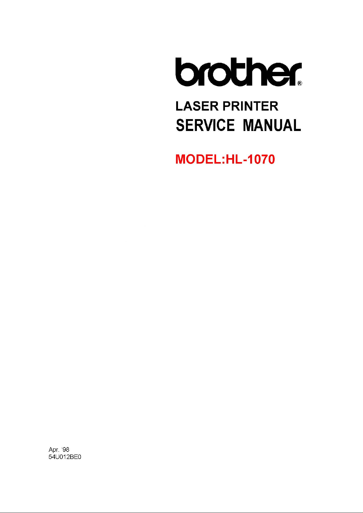
2.7 Effective Printing Area
Printable area
F
E
Labels
Envelopes
Postcards
Organizers
❍
(50 sheets)
❍
(10 sheets)
❍
(30 sheets)
❍
(10 sheets)
A
CE
✕❍
✕❍
✕❍
✕❍
B
D
F
I-7

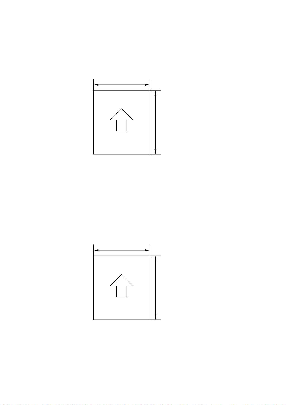
The table below shows the effective printing areas.
Size A B C D E F
210.0mm
A 4
Letter
Legal
B 5 (JIS)
B 5 (ISO)
Executive
A 5
A6 105.0mm
Organizer
(J size)
Organizer
(K size)
Organizer
(L size)
COM-10
MONARCH
C 5
DL
8.27”
(2,480 dots)
215.9mm
8.5”
(2,550 dots)
215.9mm
8.5”
(2,550 dots)
182.0mm
7.16”
(2,149 dots)
176.0mm
6.93”
(2,078 dots)
184.15mm
7.25”
(2,175 dots)
148.5mm
5.85”
(1,754 dots)
4.13”
(1,240 dots)
69.85mm
2.75”
(825 dots)
95.25mm
3.75”
(1,125 dots)
139.7mm
5.5”
(1,650 dots)
104.78mm
4.125”
(1,237 dots)
98.43mm
3.875”
(1,162 dots)
162mm
6.38”
(1,913 dots)
110mm
4.33”
(1,299 dots)
297.0mm
11.69”
(3,507 dots)
279.4mm
11.0”
(3,300 dots)
355.6mm
14.0”
(4,200 dots)
257.0mm
10.12”
(3,035 dots)
250.0mm
9.84”
(2,952 dots)
266.7mm
10.5”
(3,150 dots)
210.0mm
8.27”
(2,480 dots)
148.5mm
5.85”
(1,754 dots)
127.0mm
5.0”
(1,500 dots)
171.45mm
6.75”
(2,025 dots)
215.9mm
8.5”
(2,550 dots)
241.3mm
9.5”
(2,850 dots)
190.5mm
7.5”
(2,250 dots)
229mm
9.01”
(2,704 dots)
220mm
8.66”
(2,598 dots)
203.2mm
8.0”
(2,400 dots)
203.2mm
8.0”
(2,400 dots)
203.2mm
8.0”
(2,400 dots)
170.0mm
6.69”
(2,007 dots)
164.0mm
6.46”
(1,936 dots)
175.7mm
6.92”
(2,075 dots)
135.8mm
5.35”
(1,604 dots)
93.0mm
3.66”
(1,098 dots)
57.15mm
2.25”
(675 dots)
82.55mm
3.25”
(975 dots)
127.0mm
5.0”
(1,500 dots)
92.11mm
3.63”
(1,087 dots)
85.7mm
3.37”
(1,012 dots)
150.0mm
5.9”
(1,771 dots)
98.0mm
3.86”
(1,157 dots)
288.5mm
11.36”
(3,407 dots)
271.0mm
10.67”
(3,200 dots)
347.1mm
13.67”
(4,100 dots)
248.5mm
9.78”
(2,935 dots)
241.5mm
9.5”
(2,852 dots)
258.3mm
10.17”
(3,050 dots)
201.5mm
7.93”
(2,380 dots)
140.0mm
5.51”
(1,654 dots)
118.5mm
4.66”
(1,400 dots)
162.98mm
6.42”
(1,925 dots)
207.43mm
8.17”
(2,450 dots)
232.8mm
9.16”
(2,750 dots)
182.0mm
7.16”
(2,150 dots)
220.5mm
8.68”
(2,604 dots)
211.5mm
8.33”
(2,498 dots)
3.4mm
0.13”
(40 dots)
6.35mm
0.25”
(75 dots)
▲▲
6.01mm
0.24”
(71 dots)
▲▲
6.35mm
0.25”
(75 dots)
6.01mm
0.24”
(71 dots)
▲▲
6.35mm
0.25”
(75 dots)
▲▲
▲▲
▲▲
▲▲
6.01mm
0.24”
(71 dots)
▲▲
4.23mm
0.17”
(50 dots)
▲
▲
▲
▲
▲
▲
(Note that the paper sizes indicated here should conform to the nominal dimensions
specified by JIS.)
A4 paper must accommodate 80 characters printed in pica pitch (203.2 mm).
The dot size is based on 300 dpi resolution.
I-8

3. SAFETY INFORMATION
3.1 Laser Safety (110 - 120V Model only)
This printer is certified as a Class 1 laser product under the US Department of Health and
Human Services (DHHS) Radiation Performance Standard according to the Radiation
Control for Health and Safety Act of 1968. This means that the printer does not produce
hazardous laser radiation.
Since radiation emitted inside the printer is completely confined within the protective
housings and external covers, the laser beam cannot escape from the machine during
any phase of user operation.
3.2 FDA Regulations (110 - 120V Model only)
The US Food and Drug Administration (FDA) has implemented regulations for laser
products manufactured on and after August 2, 1976. Compliance is mandatory for
products marketed in the United States. One of the following labels on the back of the
printer indicates compliance with the FDA regulations and must be attached to laser
products marketed in the United States.
The label for Japanese manufactured products
MANUFACTURED:
BROTHER INDUSTRIES, LTD.
15-1, Naeshiro-cho, Mizuho-ku, Nagoya 467, Japan.
This product complies with FDA radiation
performance standards, 21 CFR Subchapter J.
The label for US manufactured products
MANUFACTURED:
BROTHER INDUSTRIES (USA) INC.
2950 Brother Blud., Bartlet, TN 38133, U.S.A.
This product complies with FDA radiation
performance standards, 21 CFR Subchapter J.
I-9
3.3 Caution for Laser Product (Warnhinweis für Laserdrucker)
CAUTION: When the machine during servicing is operated with the cover open, the
regulations of VBG 93 and the performance instructions for VBG 93 are
valid.
CAUTION: In case of any trouble with the laser unit, please replace the laser unit
itself. To prevent direct exposure to the laser beam, do not try to open the
enclosure of the laser unit.
ACHTUNG: Im Falle von Störungen der Lasereinheit muß diese ersetzt werden. Das
Gehäuse der Lasereinheit darf nicht geöffnet werden, da sonst
Laserstrahlen austreten können.
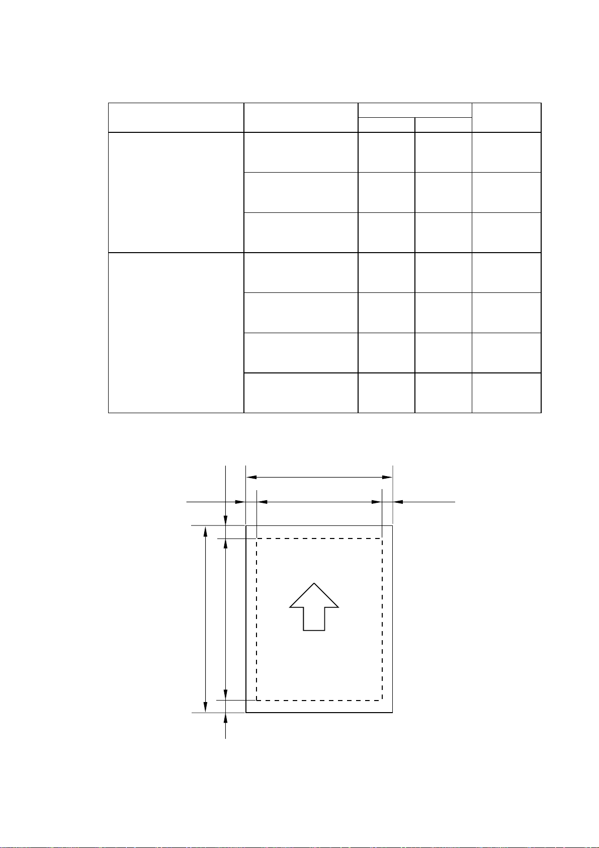
(1) Location of the laser beam window.
Fig. 1.1
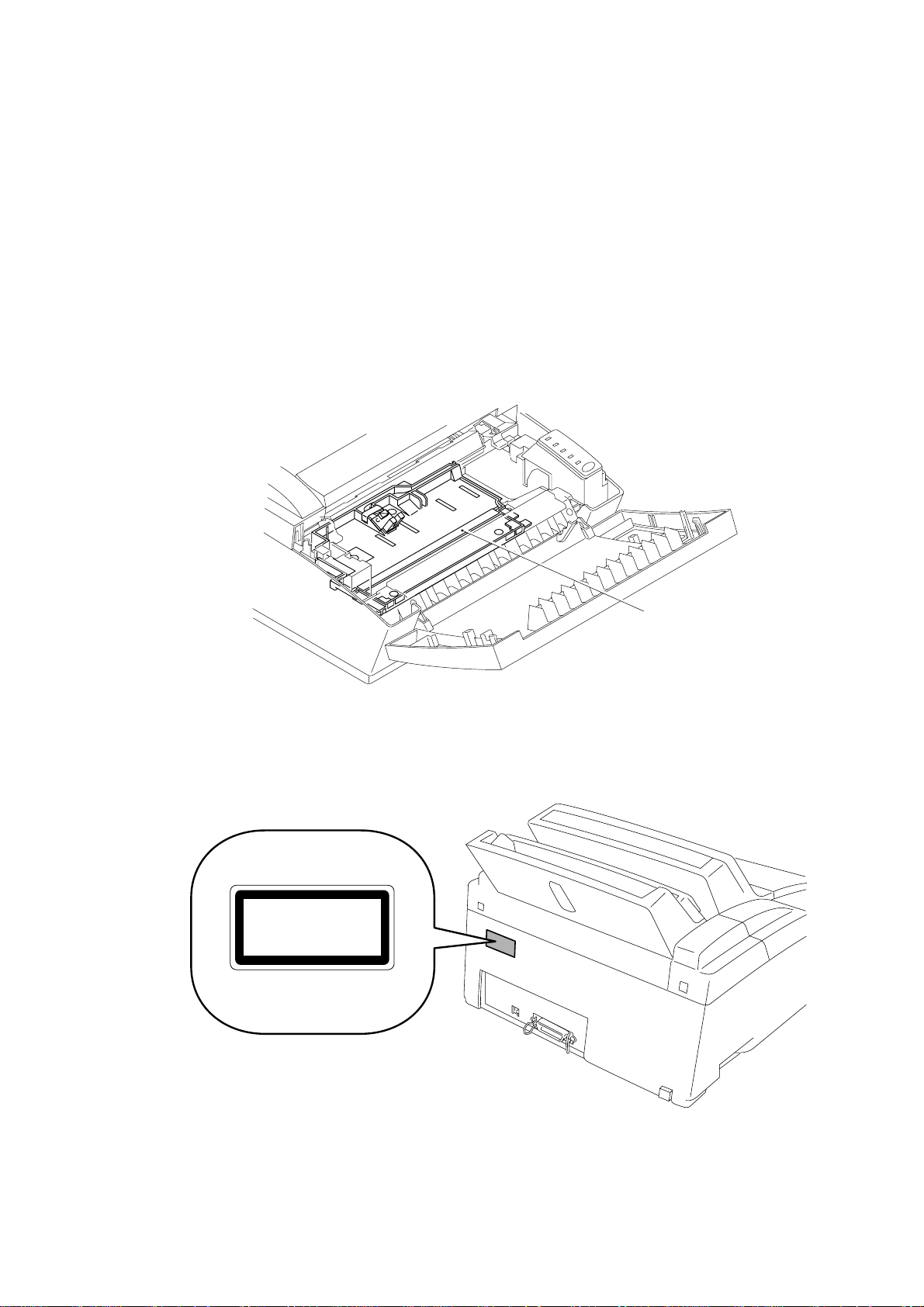
(2) Location of Caution Label for Laser Product. (200V only)
CLASS 1LASER PRODUCT
APPAREIL Å LASER DE CLASSE 1
LASER KLASSE 1 PRODUKT
Window
Fig. 1.2
I-10
CHAPTER II THEORY OF OPERATION
1. ELECTRONICS
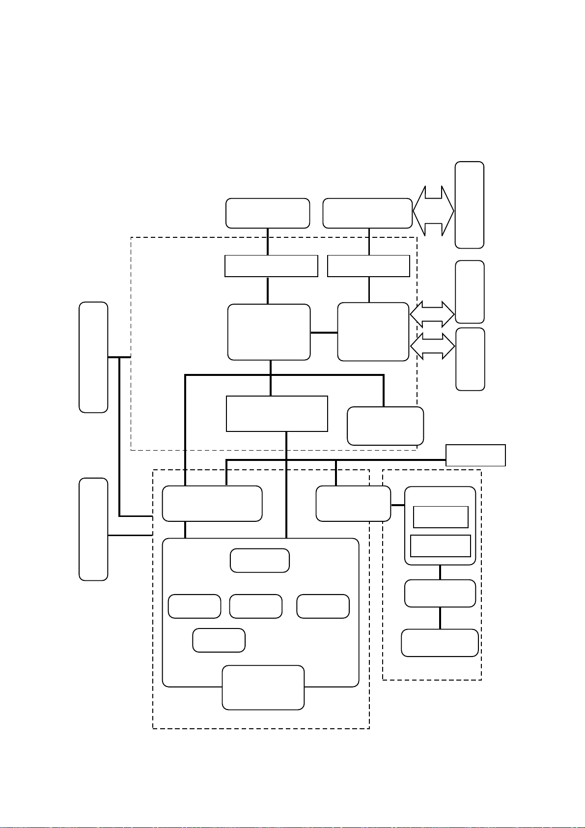
1.1 General Block Diagram
Fig. 2.1 shows a general block diagram of the HL-1070 printer.
Supply Block
Low-voltage Power
Optional RAM(SIMM)
(Max. 32Mbytes)
Control System
Expansion Memory I/O Expansion I/O
Video Control Block
Engine Control Block
Optional I/F Board
( RS-232C)
Interface Block
Operation Block
(Operation Panel)
Parallel
USB
External Device
External Device
External Device
Erase Lamp
Supply Block
High-voltage Power
Laser Scanner Unit
Drum Unit
Transfer Block
Developing
Block
Charging
Block
Image Generation System
Drum
Toner Cartridge
Fig. 2.1
Drive Block
(Stepping Motor)
Cleaner
Block
Paper Tray Unit
Paper Feeder
Manual Feed
Fixing Unit
Paper Eject Block
Paper Feed System
II-1
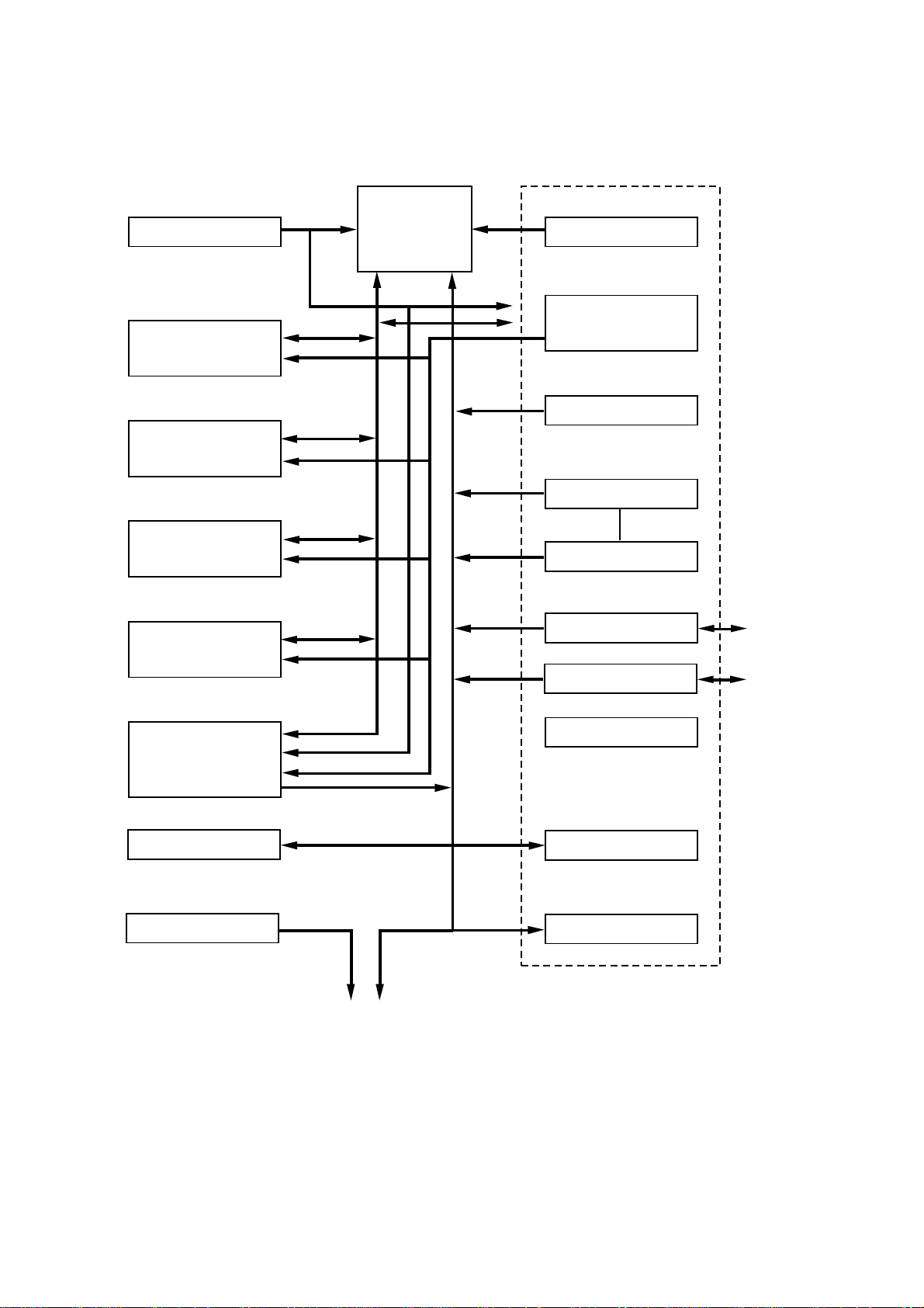
1.2 Main PCB Block Diagram
Fig. 2.2 shows the block diagram of the main PCB.
Reset Circuit
Program + Font ROM
(8Mbytes)
Flash Memory
(1Mbytes)
RAM
(4Mbytes)
CPU Core
MB86831PFV
BUS
A S I C
Oscillator (33.333333MHz)
INT
Address Decoder
DRAM Control
Timer
FIFO
DATA EXTENSION
Option RAM (SIMM)
(Max. 32Mbytes)
Option Serial I/O
(RS232C & RS422A)
EEPROM (512 x 8bits)
Motor Driver
To Panel Sensor PCB
Fig. 2.2
Parallel I/O
USB I/O
Software Support
EEPROM I/O
Engine Control I/O
To PC
To PC
II-2
1.3 Main PCB
1.3.1 CPU Core
Fig. 2.3 and 2.4 show the CPU circuit blocks on the main PCB.
The CPU is a Fujitsu MB86831PFV-G-BND which is driven at a clock frequency of
33.333333MHz.
Fig. 2.3
II-3
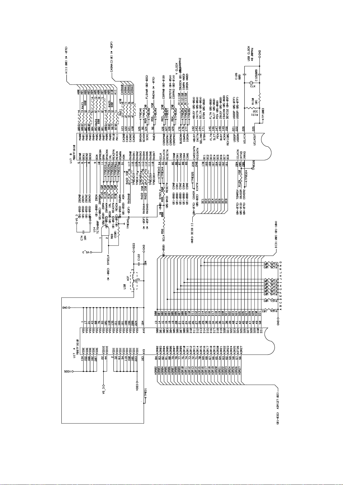
Fig.2.4
II-4

1.3.2 ASIC
The ASIC is composed of a Cell Based IC that contains the following functional blocks.
(1) Oscillator circuit
Generates the main clock for the CPU.
(2) Address decoder
Generates the CS signal for each device.
(3) DRAM control
Generates the RAS, CAS, WE, OE and MA signals for the DRAM and controls the
refresh processing (CAS before RAS self-refreshing method).
(4) Interrupt control
Interrupt levels:
Priority High 10 Reserve interrupt 1 (for debug)
9 Watch Dog Timer
8 LSB EMPTY (for VDO FIFO)
7 Timer 1
6 USB
5 XIO interrupt (RS-100M) or MIO interrupt
4 BD (for engine check)
3 Reserve interrupt 2
2 CDCC
Low 1 Timer 2
Note:
All the interrupts can be masked.
The priority of level 7, 6, and 5 are changeable from the program.
(5) Timers
The following timers are included:
Timer 1 32-bit timer
Timer 2 32-bit timer
Timer 3 Watch-dog timer
(6) FIFO
A 10Kbit FIFO is included. Data for one raster is transferred from the RAM to the
FIFO by DMA transmission and is output as serial video data. The data cycle is
10.43mhz.
II-5
(7) Parallel I/O
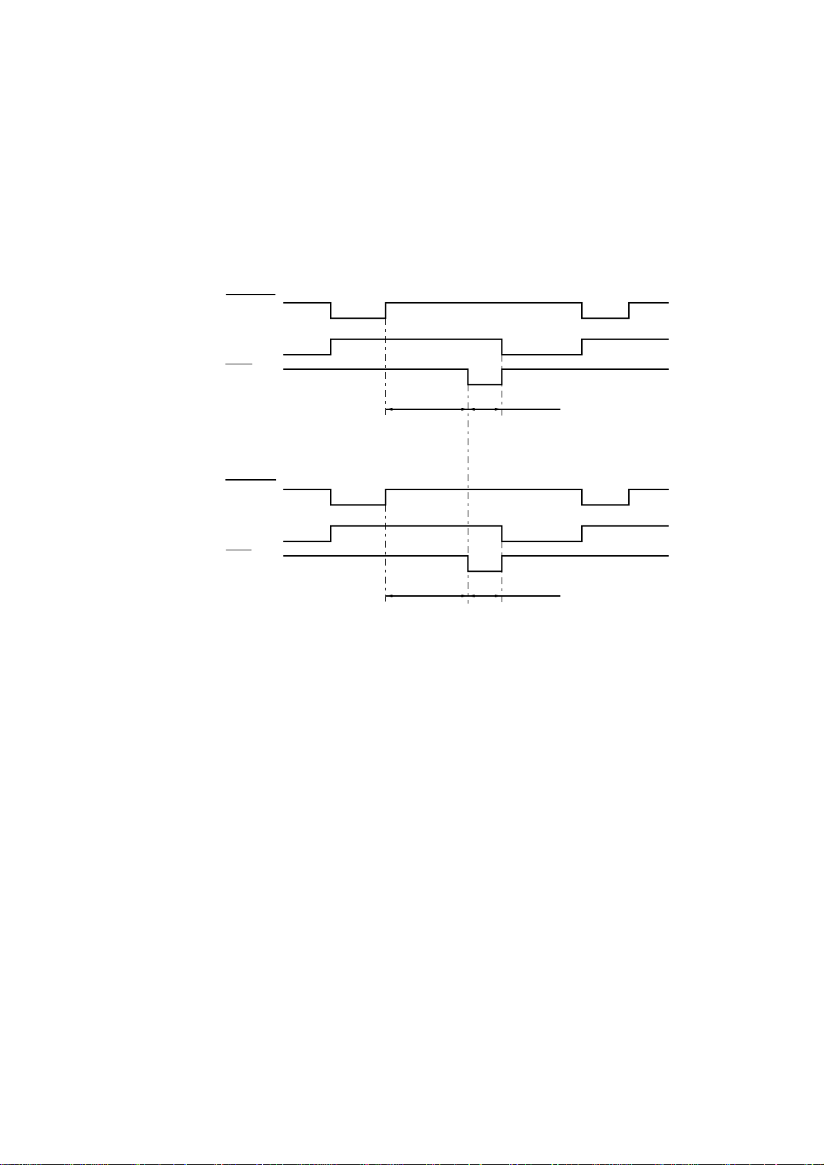
<Data receive Mode>
There are two modes in this unit. One is the CPU receive mode and the other is
the DMA receive mode. In the CPU receive mode the CPU receives the command
data from the PC, and after the CPU is switched to the DMA mode, it receives the
image data and writes it to the DRAM directly.
CPU Receive Mode
STROBE
BUSY
ACK
90 µsec
0.5 µsec
DMA Receive Mode
STROBE
BUSY
ACK
0.5 µsec1.5 µsec
BUSY goes HIGH at the falling edge of the STROBE signal. The data (8 bits) from
the PC is latched into the data buffer at the rising edge of the STROBE signal. The
pulse width of ACK varies according to the speed MODE as shown above. BUSY
goes LOW on the rising edge of ACK.
<IEEE1284 support>
This supports the IEEE1284 data transfer with the following mode.
Nibble mode
Byte mode
ECP mode
(8) Data extension
This circuit extents the compressed image data which are received from the PC,
and writes the bit map data to the FIFO.
(9) Software support
Supports 16 x 16 rotation, bit expansion, bit search, and decimal point conversion.
(10) EEPROM I/O
One output port and one I/O port are assigned.
II-6
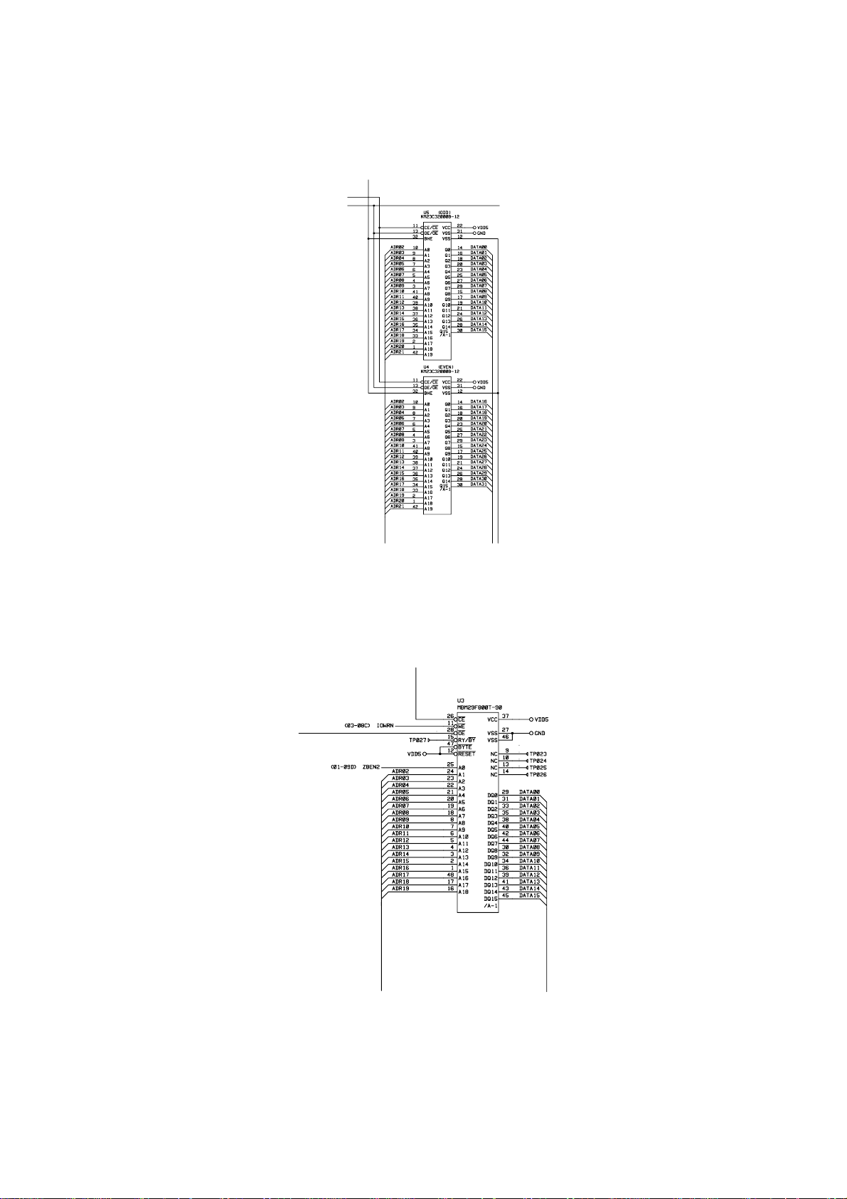
1.3.3 ROM
The program and the font data are stored in 4Mbytes of ROM. The ROM is composed of
two 32Mbit masked ROMs which are mounted in 42-pin IC sockets.
Fig. 2.5
1.3.4 Flash Memory
The program and the font data are stored in 1Mbytes of flash memory.
Fig. 2.6
II-7
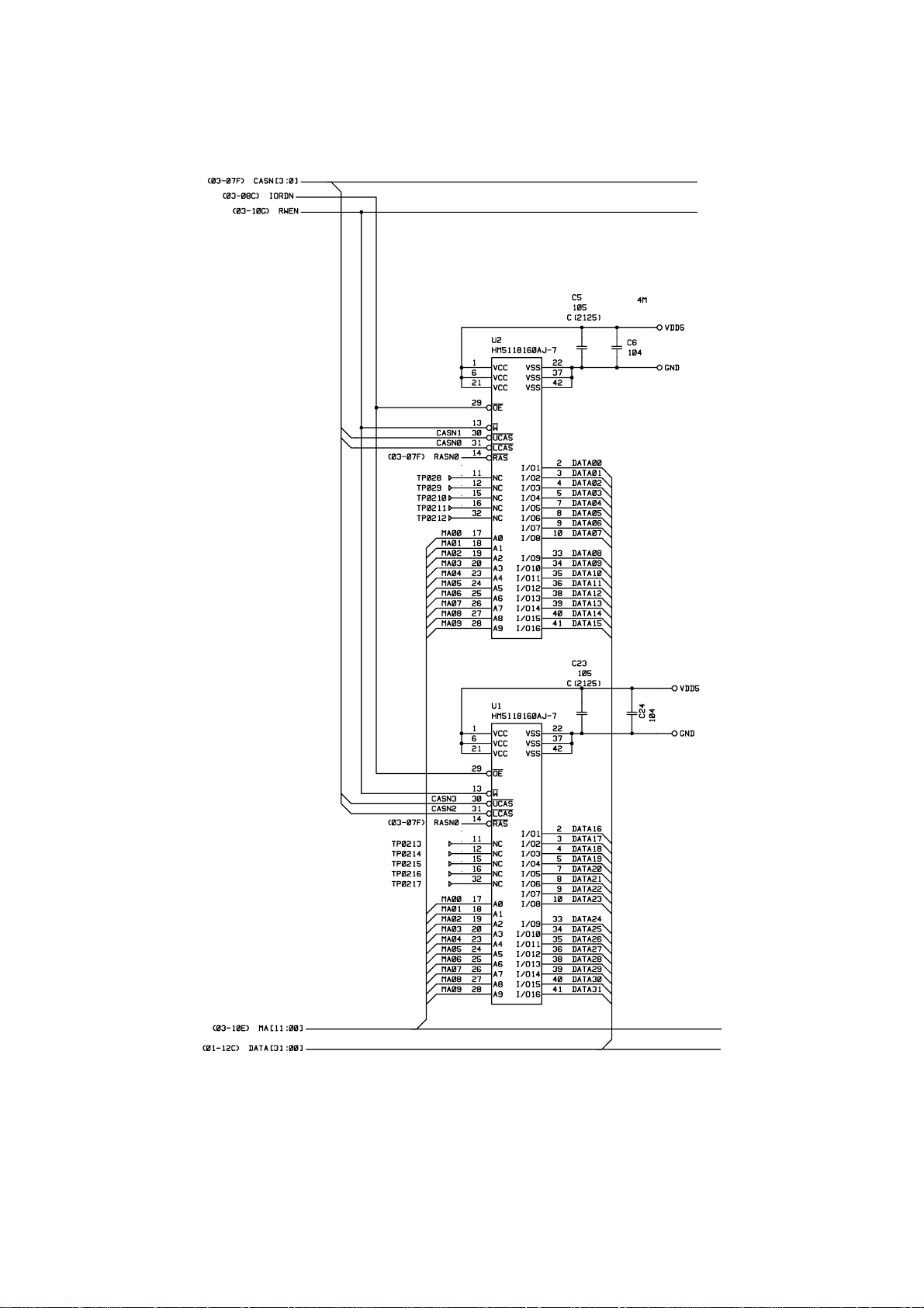
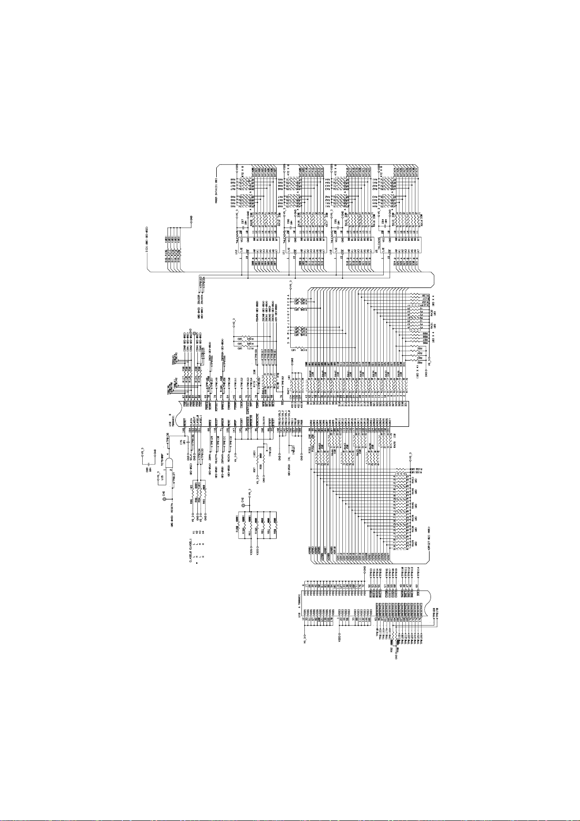
1.3.5 DRAM
Four 16Mbit DRAM (x 16bit) are used as the printer memory.
Fig. 2.7
II-8
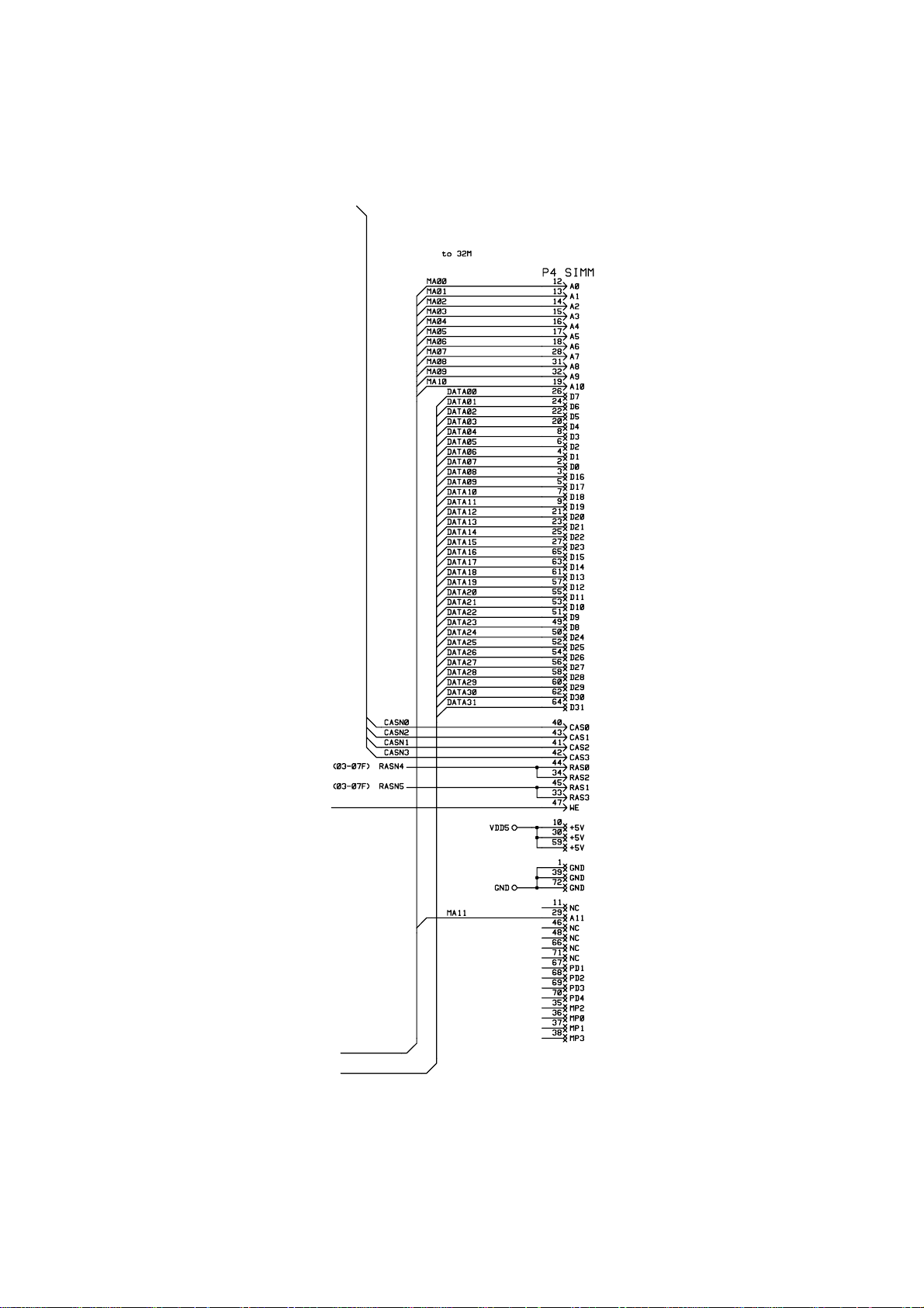
1.3.6 Optional RAM
A 32bit SIMM (72 pin) can be fitted as optional RAM. The main PCB has one slot and its
capacity is for SIMM from 1Mbytes to 32Mbytes.
Fig. 2.8
II-9
1.3.7 Optional Serial I/O
The interrupt of the serial I/O is input to the EXINT terminal of the ASIC, and recognized
by the CPU. A 32-byte space for a register is provided for this I/O, which is read and
written to by the CPU.
Fig. 2.9
1.3.8 EEPROM
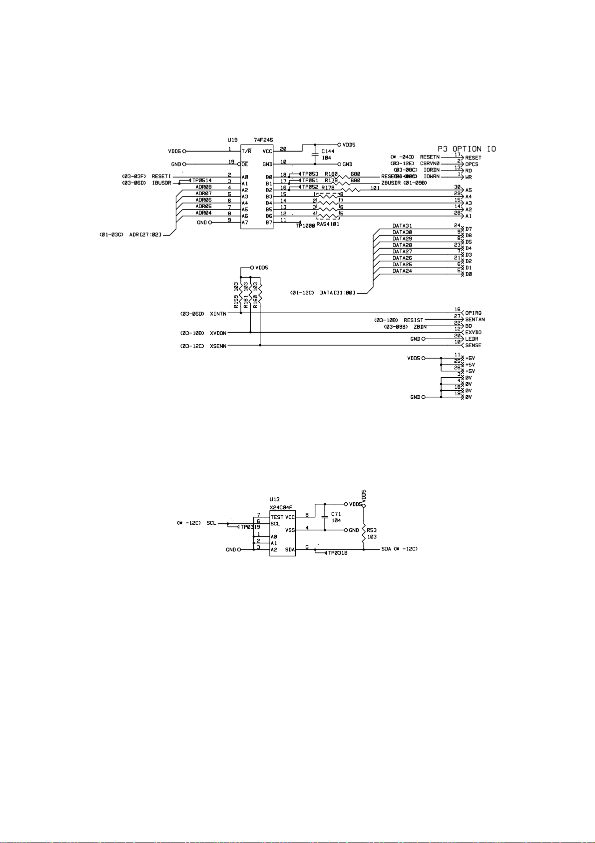
The EEPROM is an X24C04F two-wire type with a 512 x 8bits configuration.
Fig. 2.10
II-10
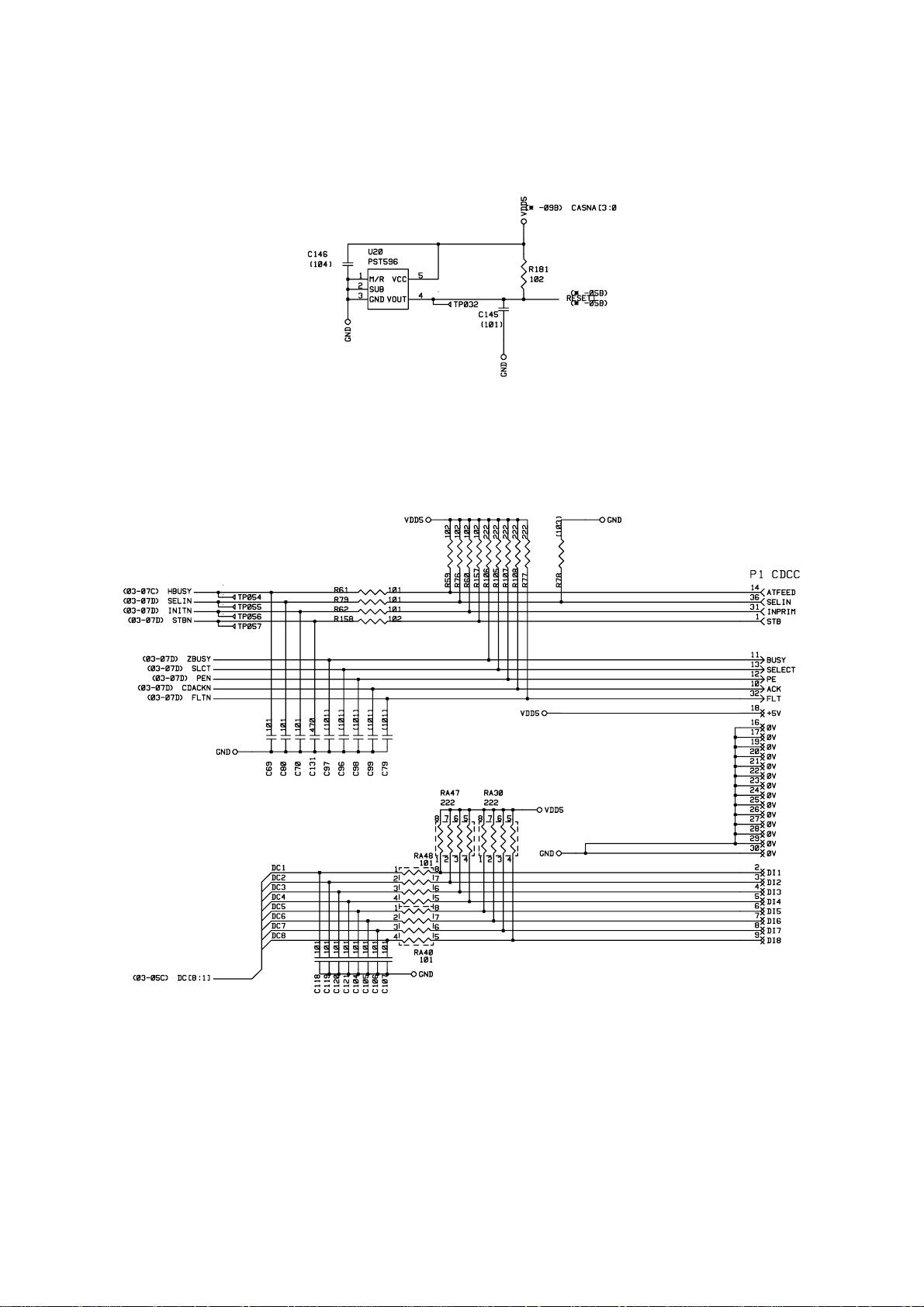
1.3.9 Reset Circuit
The reset IC is a PST596DNR. The reset voltage is 4.2V (typ.) and the LOW period of the
reset signal is 50ms (typ.).
Fig. 2.11
1.3.10 Parallel I/O
Fig. 2.13 shows the parallel interface circuit.
Fig. 2.12
II-11
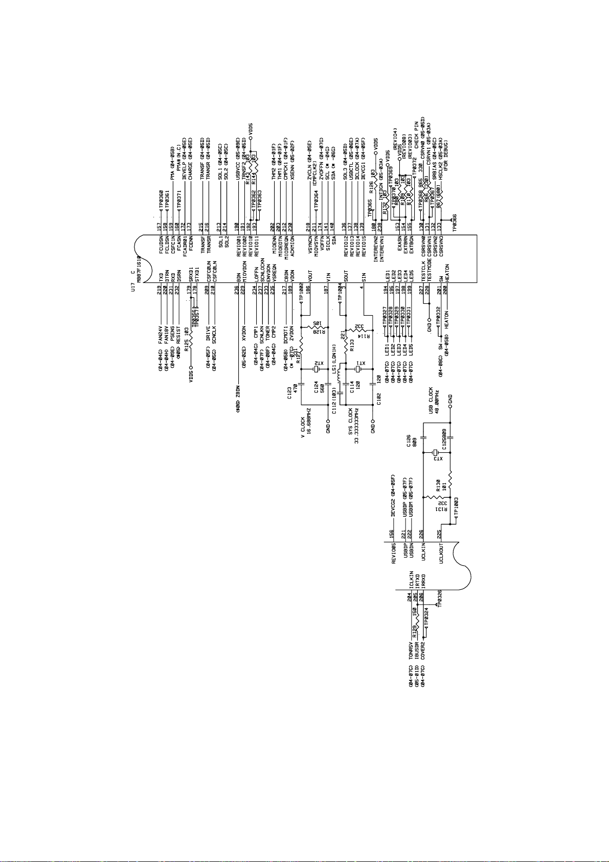
1.3.11 Engine I/O
Fig. 2.14 and 2.15 show the engine interface circuit.
Fig. 2.13
II-12
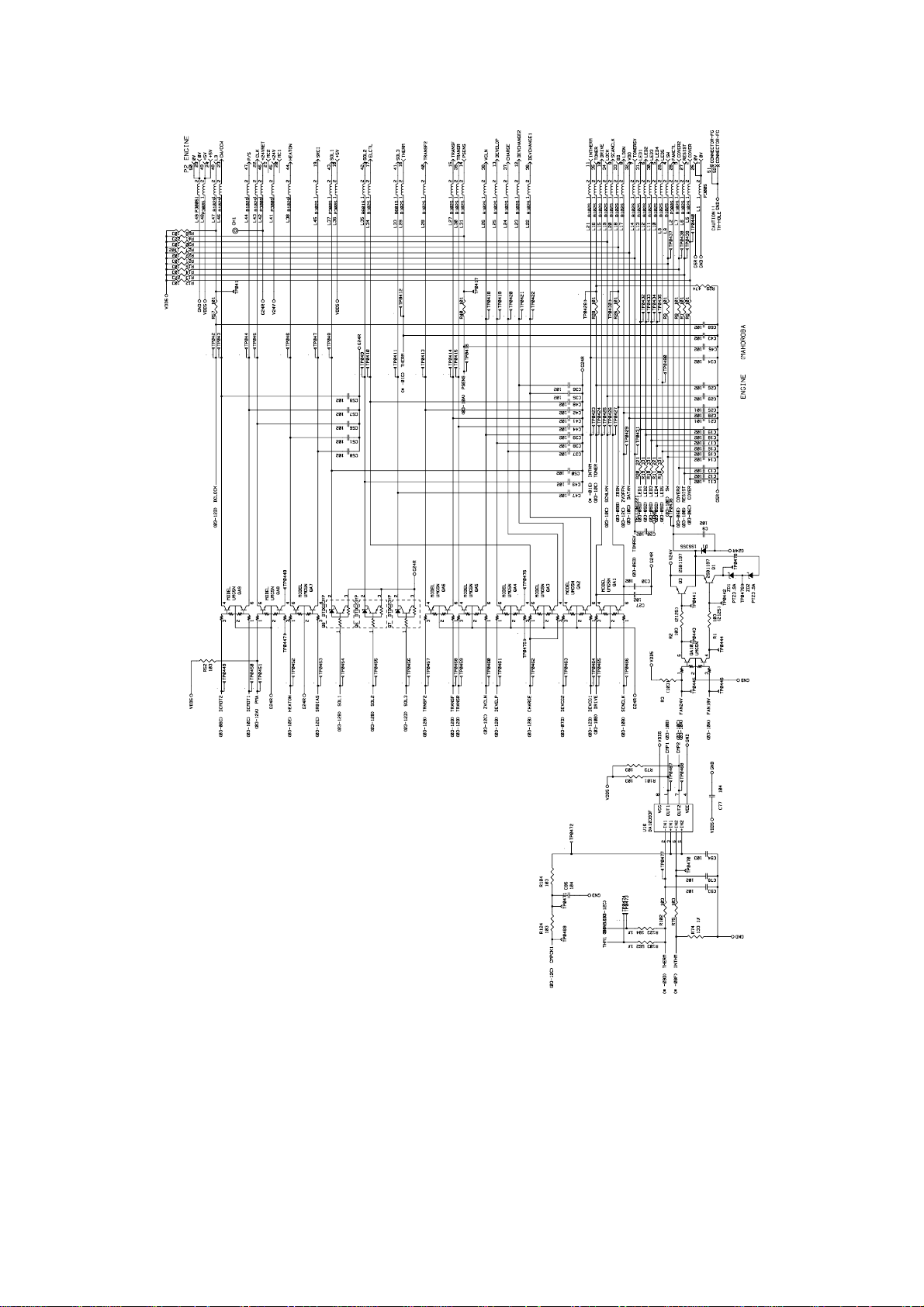
Fig.2.14
II-13
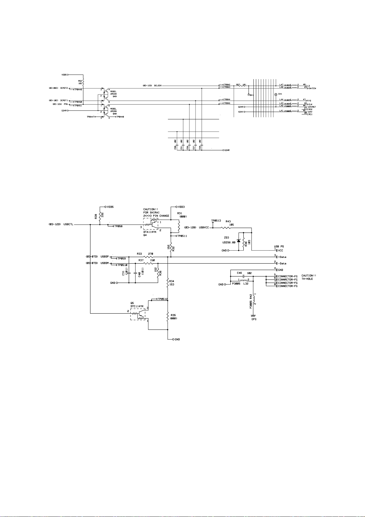
1.3.12 Paper Feed Motor Drive Circuit
A DC motor is used for paper feeding.
Fig. 2.15
1.3.13 USB I/O
Fig. 2.17 shows the USB interface circuit.
1.4 Driver PCB
The following parts are mounted on the driver PCB.
• Connectors ..................Low-voltage, high-voltage, solenoid, main motor, toner sensor,
• Registration sensor
1.5 SW Panel PCB
The following parts are mounted on the SW panel PCB.
• Operation panel ........1 Key, 5 LEDs
Fig. 2.16
laser, polygon motor, connector for main PCB
II-14
 Loading...