

Brother DB2-B773-003, DB2-B773-006, DB2-B7740, DB2-B774 Service Manual
SERVICE
MANUAL
FOR
082-8773
082-8774
082-87740
SINGLE NEEDLE
ADJUSTABLE
TOP AND
BOTTOM FEED
LOCK
STITCH
MACHINE
CONTENTS
I
NAMES
OF
MAIN
PARTS
I·
. . . . . . . . . . . . . . . . . . . . . . . . . . . . . . . . . . . . . . . . . . . . . 1
I
SPECIFICATIONS
I . . . . . . . . . . . . . . . . . . . . . . . . . . . . . . . . . . . . . . . . . . . . . . . . . . . . . 3
I
MECHANICAL
DESCRIPTIONS
I·.........................................
5
rn
Upper shaft and needle bar mechanism 0 0 0
0.
0 0 0 0
0.
0 0 0 0 0 0 0 0 0 0 0 0 0 0 5
[2}
Lower shaft and rotary
hook
mechanism . o o
••
0 0 o o 0 0 0 0 0 • 0 0 • 0 o
••
0 0 5
IJJ
Upper feed mechanism . 0 0
0. 0 0.
0 0
•• 0 0. 0 0. 0. 0.
0 0 0 0 0
0. 0 0.
0 0 0 0 0
0.
0 6
1!1
Feed
mechanism
..
0
••
0 • 0 0 0 • 0 0 • 0 0
••
0 0 • 0 0 • 0 • 0 • 0 0 • 0 0 0 0 0 0 • 0 0 • 0 0 0 0 0 7
~
Feed
adjusting mechanism and quick reverse mechanism 0 0 0 0 0 0 0 0 0 8
[§]Upper feed mechanism and shirring mechanism (subclass -006) 0 0 0 0 9
[l]Threadtrimmer
00000
oooooooooooo
••• o •• o .o.o.o.ooooooooooooooooo
10
liD
Tension release
...
0
••
0 • 0 • 0 • 0 0
••
0 0 0 • 0 0 0 0 0 0 • 0 • 0 0 • 0 • 0 0 0 0 0 0 0 0 0 0 0 0 0 0
13
~Thread
wiper
(subclasses
-400, -900) 0 0 • 0 0 0
0.
0 0
0.
0 0 0 0 0 0 0 • 0 0 0 0 0
0.
0 0
13
1m
Automatic
presser bar
lifter
mechanism (subclass -900) 0
0.
0 0 0 0 0 0 0 0 0 14
lllJ
Lubrication
me~han
ism
. 0 0 0 0 0 0 0 0 0 0 0 • 0 0 0 0 0 0 • 0 • 0 0 0 0 0 0 0 0 0 0 0 0 0 0 0 0 0 0 0
15
I
DISASSEMBLY
,.
. . . . . . . . . . . . . . . . . . . . . . . .
..
. . . . . . . . . . . . . . .
..
. .
.. . ..
. . . . . 17
[I]Machinecovers
·o···ooooooooo··o•oooooo•o•o•ooo·ooooooooooooooo
17
lZJ
Presser
foot
mechanism 0 • 0 • 0 0 • 0 0 • 0 • 0
••
0 • 0 • 0 • 0 0 • 0 0 • 0 0 0 0 0 0 • 0 0 0 • 0 0
18
[ID
Upper feed mechanism . 0 • 0 0 0 0 0 0 0 0 0 0 0 0 0 0 • 0 • 0 • 0 0 • 0 0
••
0 0 0 0 0 0 0 0 0 0 0 0
18
1!1
Rotary
hook
mechanism 0 • 0 0 0 0 0 0 0 • 0 • 0 0 • 0 0 0 • 0 • 0 0 • 0 0 • 0 0 0 • 0 0 0 0 0 0 0 0 0
19
f.SlThreadtrimmer
...
ooooooooooooooooooooooooooooo•ooooooooooooooo
19
[§]
Feed
mechanism 0 • 0 0 0 0 0 0 0 0 0 0 • 0 0
••••
0 0 • 0 0 0 • 0
••••
0 0 0 0 0 0 0 0 0 0 0 0 0 0 • 0
20
[1]
Needle bar mechanism .
0.
0 0 0 0 0 0 0 0
0. 0 0.
0.
0. 0 •• 0 •••••
0 0 0 0 0 0 0 0 0 0 0 0
21
I
ASSEMBLY
I.
. . . . . . . . . . . . . . . . . . . . . . . . . . . . . . . . . . . . . . . . . . . . . . . . . . . . . . . . . .
22
[]
Needle bar mechanism 0 • 0 0 0 • 0 0 0 0 0 0 0 0 0 0 0 0
••
0 0 • 0 • 0 0 0 0 0 0 0 0 0 0 0 0 0 0 • •
22
lZJ
Feed
mechanism 0 0 0 0 • 0 0 • 0 0 0 0 0 0 0 0 0 0 0 0 0 0 0 0 0 0 0 0 0 0 0 0 0 0 0 0 0 0 0 0 0 0 0 0 0 0
~
23
[ID
Thread
trimmer
. 0 0 0 0 • 0 0 • 0 0 0 0
·0
0 0 0 0 0 0 • 0 0 • 0 • 0 • 0 • 0 0 0 0 0 0 0 0 0 0 0 0 0 0 • 0 0 0
25
1!1
Rotary
hook
mechanism . 0 0 0 0 • 0 0 0 0 0 0 • 0 0 • 0 0 0 • 0 0 • 0 0 • 0 0 0 0 0 0 0 0 0 • 0 0 0 •
27
~
Presser
foot
mechanism 0 0 • 0 0 • 0 0
••
0 0 • 0 0 • 0 0 0 • 0 0 • 0 0 • 0 0 0 0 0 0 • 0 0
••
0 0 0
28
rnJ
Upper feed mechanism 0 0
0.
0 0 0 0
0.
0.
0. 0 0.
0 0
0. 0 0.
0 0 0 0 0 0
0.
0.
0 0 0 0 0 0 0
29
[1]
Machine covers 0 0 0 0 0 0 0 0 0 0 0 0 0 0 0 0 0
••
0 0 • 0 • 0 0 • 0 0 • 0 0
••
0 • 0 0
••
0 • 0 • 0 0 0 0
30
'ADJUSTMENT ,
........................................................
31
[I] Adjusting
the
timing
between needle and rotary
hook
0 0 0 o o 0 o o o o o 0
31
[l]
Adjusting
the
timing
between needle and feed
0. 0 0.
0 0 0 0 0
0. 0 0.
0 0 0 0
32
[ID
Adjusting
the
fofward
and backward stitch lengths 0 0 0 0 0 0
0. 0 0.
0 0
0.
33
1!1
Zeroing feed regulator and adjusting reverse lever
0.
0. 0 0.
0 0 0
0.
0 0 0 0 34
~Adjusting
the
timing
of
upper
feed horizontal movement 0 0 0
0.
0 0 0 0
35
rnJ
Adjusting
the
timing
of
the
upper
feed vertical movement 0 0 0 0 0 0 0 0 0 36
I1J
Adjusting presser
foot
0 0 0 • 0 0 • 0 0 0 0 • 0 0 0 0 0 0 0 • 0 0 0 0 0 • 0 0 0 0 0 0 0 0 0 0 0 0 0 0 0 0 37
liD
Adjusting
thread
trimmer
. . . . . . . . . . . . . . . . . . . . . . . . . . . . . . . . . . . . . . 38
liD
Adjusting tension release . . . . . . . . . . . . . . . . . . . . . . . . . . . . . . . . . . . . . . .
39
IDl
Adjusting
thread
tension . . . . . . . . . . . . . . . . . . . . . . . . . . . . . . . . . . . . . . . 40
lll1
Adjusting synchronizer {082-8774) . . . . . . . . . . . . . . . . . . . . . . . . . . . . . .
41
1121
Adjusting
thread
wiper
. . . . . . . . . . . . . . . . . . . . . . . . . . . . . . . . . . . . . . . . . 42
1131
Adjusting
potentio-meter
(87740) . . . . . . . . . . . . . . . . . . . . . . . . . . . . . . . 43
1m
Checking feed mechanism
weight
(87740) . . . . . . . . . . . . . . . . . . . . . . . .
44
ll51
Adjusting sensor position . . . . . . . . . . . . . . . . . . . . . . . . . . . . . . . . . . . . . . . 45
Ill
Adjusting
the
indication
of
the
distance
between
needle
hole
and
sensor (877
40) . . . . . . . . . . . . . . . . . . . . . . . . . . . . . . . . . . . . . . . . . . . . . . . . . 46
I
REPLACEMENTS
I.
. . . . . . . . . . . . . . . . . . . . . . . . . . . . . . . . . . . . . . . . . . . . . . . . . . . . . . 47
li1
Replacing Solenoids . . . . . . . . . . . . . . . . . . . . . . . . . . . . . . . . . . . . . . . . . . . 47
l1l
Replacing tension release
wire
. . . . . . . . . . . . . . . . . . . . . . . . . . . . . . . . . .
50
~
Replacing
bobbin
tension spring . . . . . . . . . . . . . . . . . . . . . . . . . . . . . . . .
50
~Replacing
photo-cell and
reflector
{87740) . . . . . . . . . . . . . . . . . . . . . . .
51
[SJ
Replacing Synchronizers . . . . . . . . . . . . . . . . . . . . . . . . . . . . . . . . . . . . . . . .
53
I OPTIONAL
EQUIPMENT!................................................
54
li1
Thread
wiper
. . . . . . . . . . . . . . . . . . . . . . . . . . . . . . . . . . . . . . . . . . . . . . . . . . 54
l2l
Presser
foot
lifting
solenoid set . . . . . . . . . . . . . . . . . . . . . . . . . . . . . . . . . .
55
I TROUBLESHOOTING
GUIDE
I.
. . . . . . . . . . . . . . . . . . . . . . . . . . . . . . . . . . . . . . . . . . .
59

INAMESOF
MAI
N PARTS I
[082-8773
-003]
0 Needle
bar
@ Thread retainer
@ Presser
regulating
screw 0 Tension
nut
[082-8774]
0 Needle bar @ Pre-tension
@Presser
regulating
screw 0
Tens
ion nut
Co
ntr
ol panel {87740)
SPICII>=
~
~-m
~nrg
~~
oooo
1 H +
EXE~A·
brother
r 3
~
~
Fo4l
fo
4 0 l
+0.5
1om
o@
o~ ul!l)il~
~~ ~·lruM
I
H -
W"~l"'
-1-
[082-8773-006]
A
@Machine
pulley
@ Reverse lever
[082-87740]
@Machine
pulley
@ Reverse lever
B
c 0
COftRECTlON
IDDDD
~
I +
I:::
I
r3Jrill§~
'r\~:
~
tc
~~~
STTTQtES
+!-!..
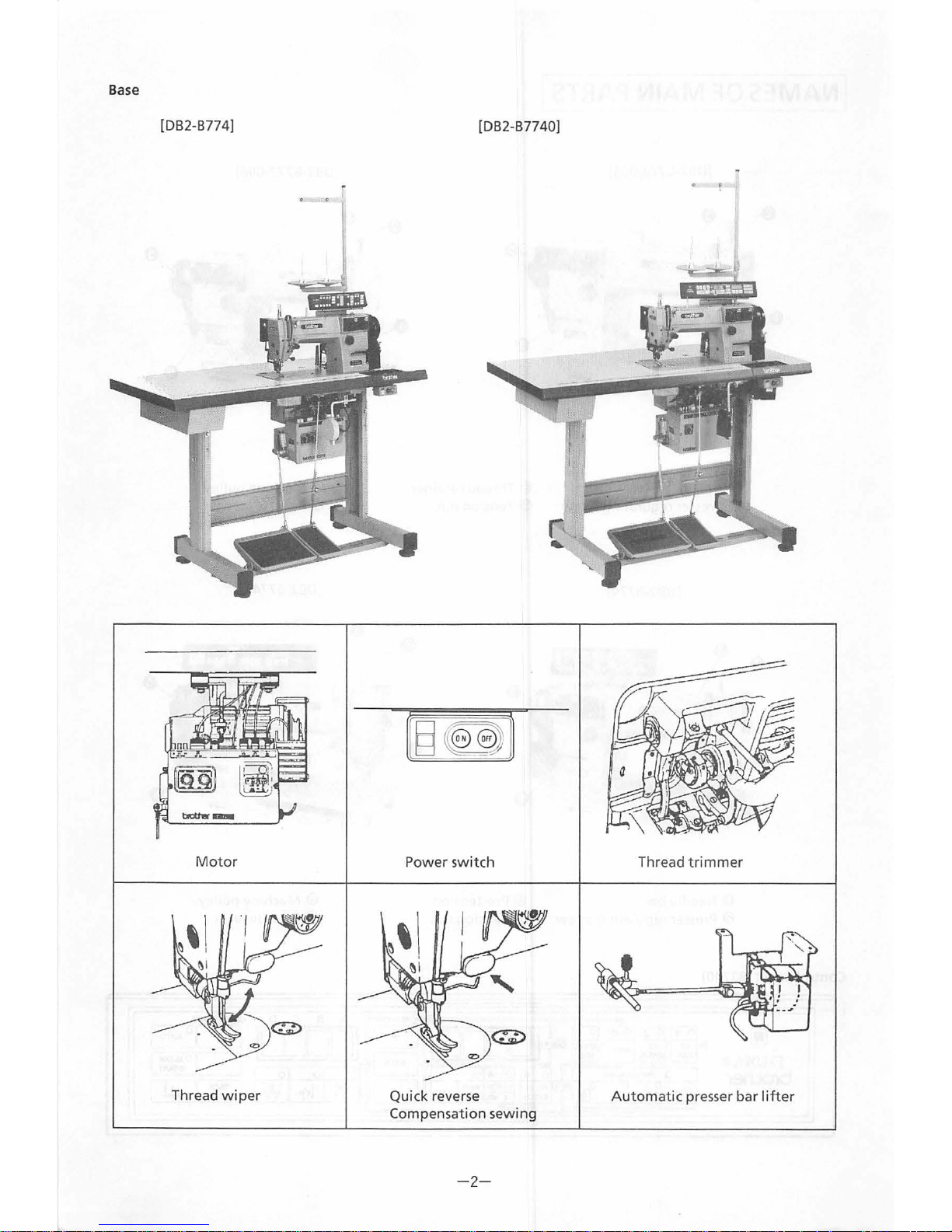
Base
[DB2-B774]
Motor
Thread w iper
[DB2-B7740]
Power swi
tch
Quick rever
se
Compensation
se
.
w
1ng
-
2-
Thread t
rimmer
Automatic
presser bar I i
fter
SPECIFICATIONS
I
..,
BROTHER
INDUSTRIES,
LTD.
082-8773-poq
MADE
IN
JAPAN
""
.J
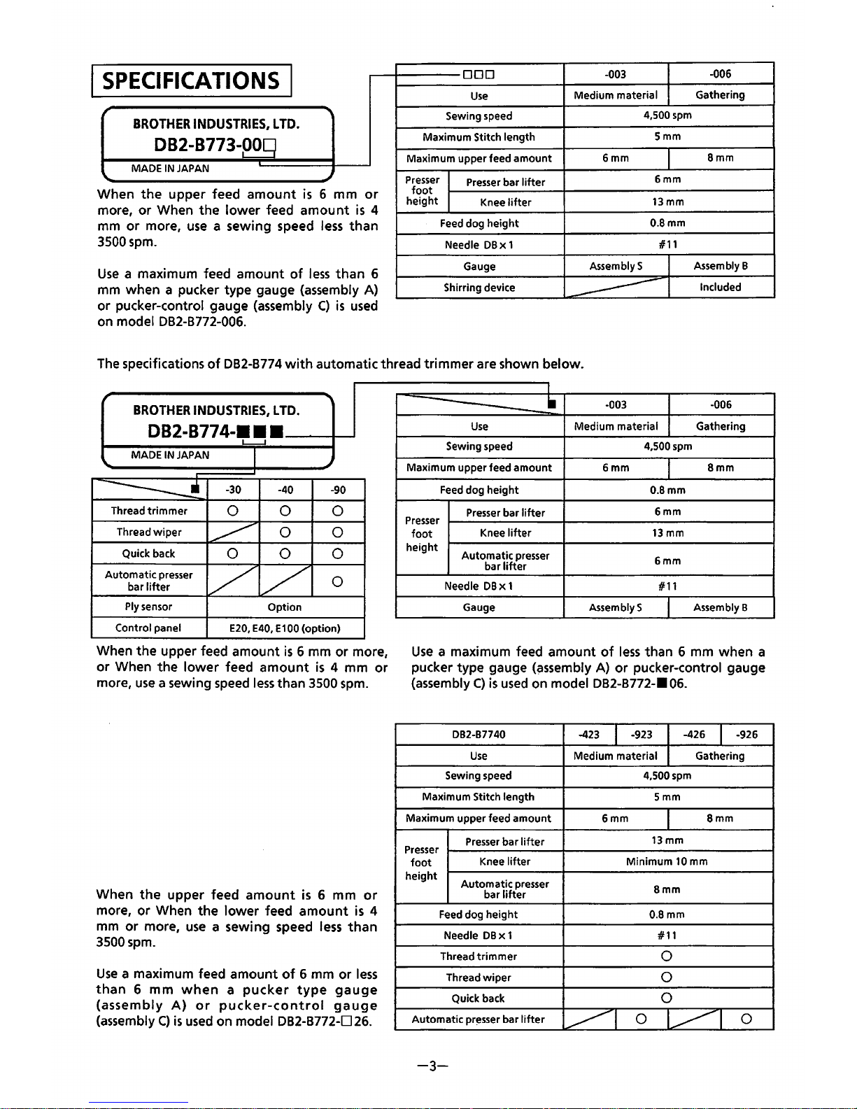
w hen
the
upper feed
amount
is
6 mm
or
more,
or
When
the
lower
feed
amount
is
4
mm
or
more,
use
a sewing speed
less
than
3
500
spm.
Use
a maximum feed amount
of
less
than
6
m m when a pucker type gauge (assembly A)
or pucker-control gauge (assembly
C)
1s
used
on model 082-8772-006.
ODD
Use
Sewing speed
Maximum Stitch length
Maximum upper feed
amount
Presser
Presser
bar
lifter
foot
height
Knee
lifter
Feed
dog
height
Needle
DBx
1
Gauge
Shirring device
-003
-006
Medium material
Gathering
4,500
spm
Smm
6mm
Bmm
6mm
13mm
O.Bmm
#11
AssemblyS
Assembly B
-----------
Included
The
specifications
of
082-8774
with
automatic thread trimmer are shown below.
BROTHER
INDUSTRIES,
LTD.
082-8774-···
L--..J
MADE
IN
JAPAN
I
.J
==------.!
-30 -40
-90
Thread
trimmer
0 0 0
Thread
wiper
~
0
0
Quick back
0
0 0
/ /
Automatic
presser
0
bar
lifter
Ply sensor
Option
Control
panel
E20, E40,
E100
(option)
When the upper feed amount
is
6 mm or more,
or
When
the
lower
feed
amount
is
4 mm
or
more,
use
a sewing
speed
Jess
than
3500
spm.
When
the
upper feed
amount
is
6 mm
or
more, or When
the
lower feed
amount
is
4
mm
or
more,
use
a sewing speed
less
than
3500spm.
Use
a maximum feed amount
of
6 mm or
less
than 6 mm
when a pucker
type
gauge
(assembly
A)
or
pucker-control
gauge
(assembly
C)
is
used
on model 082-8772-D
26.
I
---------·
-003
-006
Use
Medium material Gathering
Sewing speed 4,500spm
Maximum upper feed
amount
6mm
Bmm
Feed
dog
height
O.Bmm
Presser
bar
lifter
6mm
Presser
foot
Knee
lifter
13mm
height
Automatic
presser
6mm
bar
lifter
Needle DBX 1
#11
Gauge Assembly$ Assembly B
Use
a maximum feed amount
of
less
than 6 mm when a
pucker type gauge
(~ssembly
A)
or
pucker-control gauge
(assembly
C)
is
used
on model DB2-B772-•
06.
DB2-B7740
-423
I
-923
-426
I
-926
Use
Medium material Gathering
Sewing speed
4,500spm
Maximum Stitch length Smm
Maximum upper feed
amount
6mm
Bmm
Presser
bar
lifter
13mm
Presser
foot
Knee
lifter
Minimum 10 mm
height
Automatic
presser
bar
lifter
Bmm
Feed
dog
height
O.Bmm
Needle
DBx
1 #11
Thread
trimmer
0
Thread
wiper
0
Quick back
0
Automatic
pr~sser
bar
lifter
~I
0
~I
0
-3-
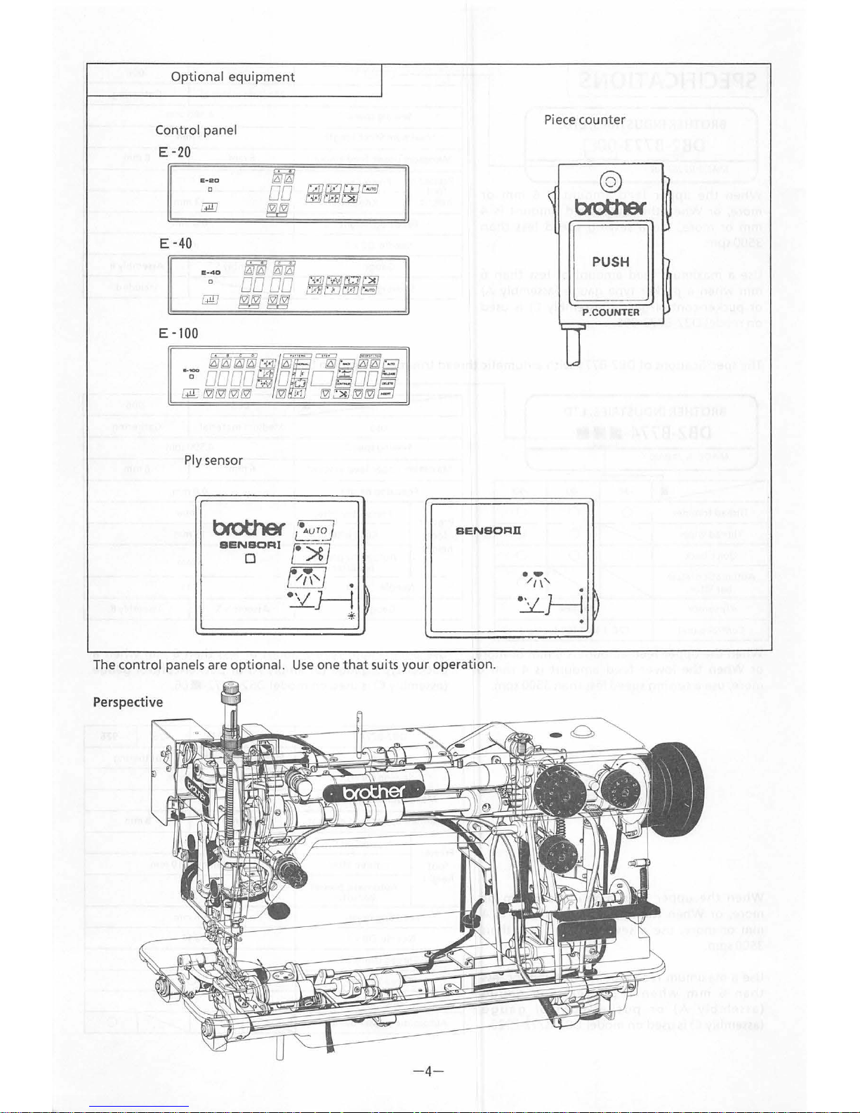
Optional
equipment
Con
trol panel
E -20
E-RD
c
E -
40
11-40
c
E -100
Ply sensor
I
SENSORfi
Th
e con
trol
panels are optional.
Use
one
that
suits y
our
operation.
Perspective
-4-
Piece counter
@
brother
EJ
P.
COUNTER
u
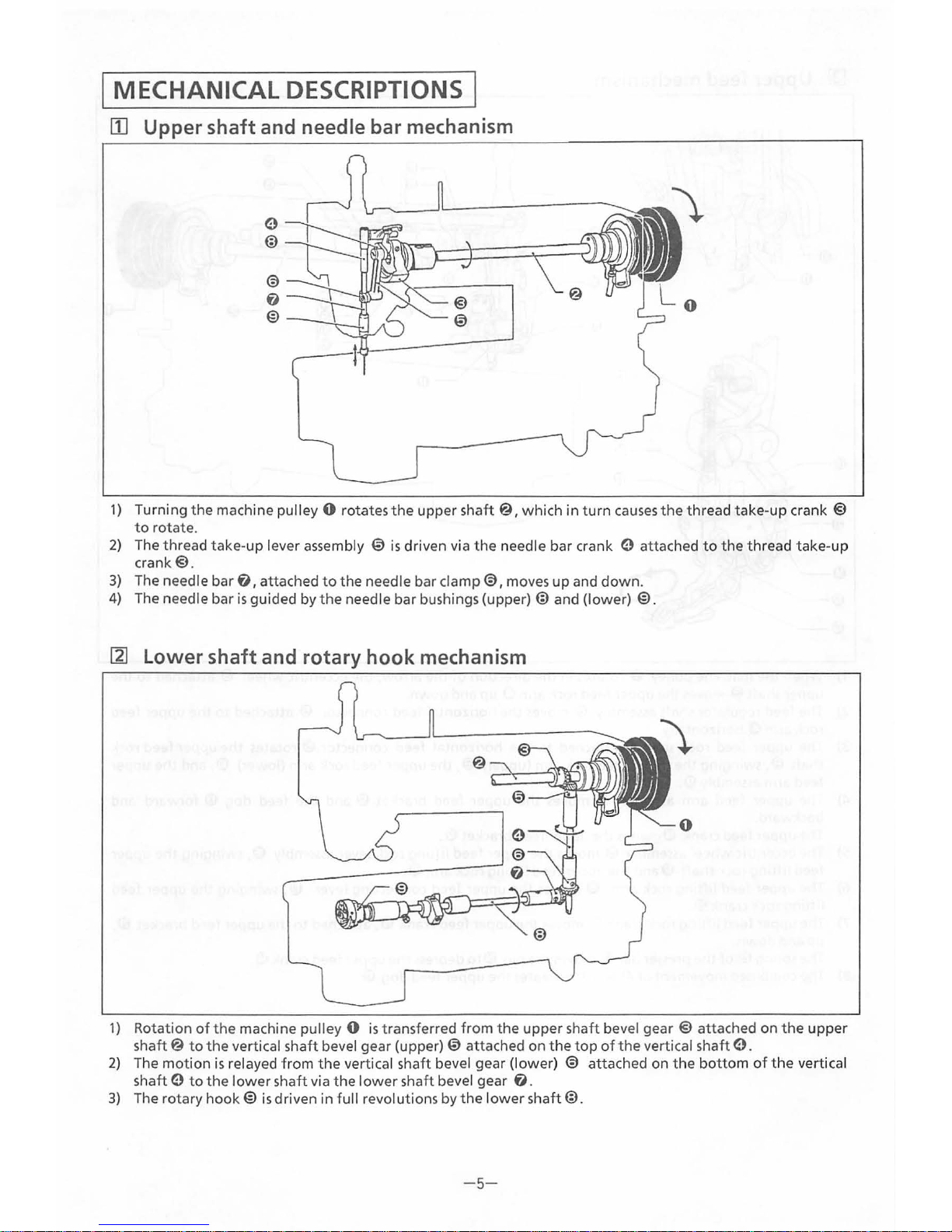
MECHANICAL DESCRIPTIONS
III Upper shaft and needle bar mechanism
1)
Turning
the
machine pulley 0 rotates the upper
shaft@ I which
in
turn
causes
the
thread
take-up
crank @
to
rotate.
2)
The thread take-up lever assembly
€)
is
driven via
the
needle bar crank e attached
to
the
thread
take-up
crank@.
3)
The needle bar
f)
I attached
to
the
needle bar
clamp@
I moves
up
and
down.
4) The needle bar
is
guided by
the
needle bar bushings
(upper)@
and (lower) @.
l1l
Lower shaft and rotary hook mechanism
1)
Rotation
of
the
machine
pulley 0 is
transferred
from
the
upper
shaft bevel
gear@
attached on
the
upper
shaft@
to
the
vertical shaft bevel gear (upper)@ attached on
the
top
of
the
vertical shaft e.
2)
The
motion
is
relayed
from
the
vertical shaft bevel gear (lower) @ attached on
the
bottom
of
the
vertical
shaft e
to
the lower
shaft via
the
lower
shaft bevel gear
f)
.
3)
The rotary
hook@
is
driven in full revolutions by
the
lower
shaft@.
-5-

[1]
Upper feed mechanism
1)
When
the
machine pulley 0 rotates
in
the
direction
of
the
arrow,
the
eccentric wheel
@attached
to
the
upper
shaft@
moves
the
upper feed rock arm a
up
and down.
2)
The feed regul
ato
r shaft assembly ® moves the horizontal feed connector @ attached
to
the
upper
feed
rock arm
a
horizontally
.
3) The
upper
feed rock shaft
f)
attached
to
the horizontal feed connec
tor
@ rotates
the
upp
er
feed rock
shaft
@,swinging
the
upper feed rock arm (upper)
@,the
upper
feed rock arm (lower)
@,and
the
upper
feed arm assembly
m.
4)
The
upper
feed arm assembly
ID
moves
the
upper
feed brac
ket
® and the feed dog ®
forward
and
backward.
The
upper
feed crank IDgu i
des
the
upper
feed
bracket®.
5)
The eccentric wheel
assem
bly ® moves
the
upper feed
lifting
rock lever assembly
@,swinging
the
upper
feed
lifting
rock
shaft
(f) and
the
upper feed
lifting
rock
arm®.
6)
The
upper feed
lifting
rock arm ® moves
the
upper
feed connecting lever ®, swinging the upper feed
lift
ing rock cran
k@.
7)
The upper feed
lifting
rock
crank@
moves
the
upper
feed crank
(9,
attached
to
the
upper feed
bracket
@,
up and
down.
The
spring ®
of
the
presser bar
til
mo
ves
the
pin
fnto
depress
the
upper feed crank
(9.
8)
The
combined movement
of
4) and
7)
operates
the
upper
feed dog
®.
- 6-
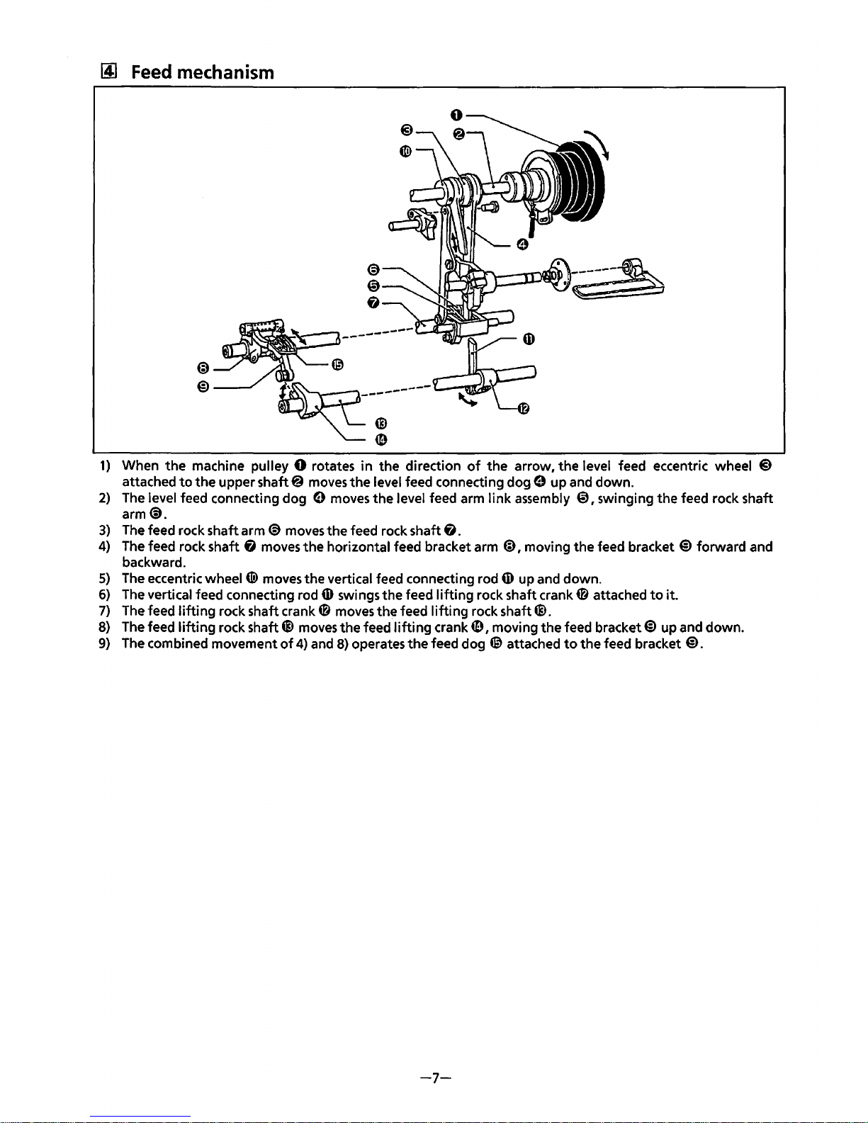
lAJ
Feed
mechanism
@
@---
---------
@
~
----
1)
When the machine pulley 0 rotates in the direction
of
the
arrow, the level feed eccentric wheel @
attached
to
the
upper shaft@
moves
the
level feed connecting dog 0 up and down.
2)
The
level feed connecting dog 0 moves the level feed arm link assembly @,swinging the feed rock shaft
arm
<9.
3)
The
feed rock shaft arm @
moves
the feed rock shaft & .
4)
The
feed rock shaft & moves
the
horizontal feed bracket arm
ED,
moving the feed bracket
@)
forward and
backward.
5)
The
eccentric wheel
CID
moves the vertical feed connecting rod
4D
up and down.
6)
The
vertical feed connecting rod
4D
swings the feed
lifting
rock shaft crank 0 attached
to
it.
7)
The
feed
lifting
rock shaft crank 0
moves
the feed
lifting
rock shaft@.
8)
The
feed
lifting
rock shaft@
moves
the feed
lifting
crank~,
moving
the
feed bracket@) up and down.
9)
The
combined movement
of
4)
and
8)
operates
the
feed dog @ attached
to
the feed bracket
@).
-7-
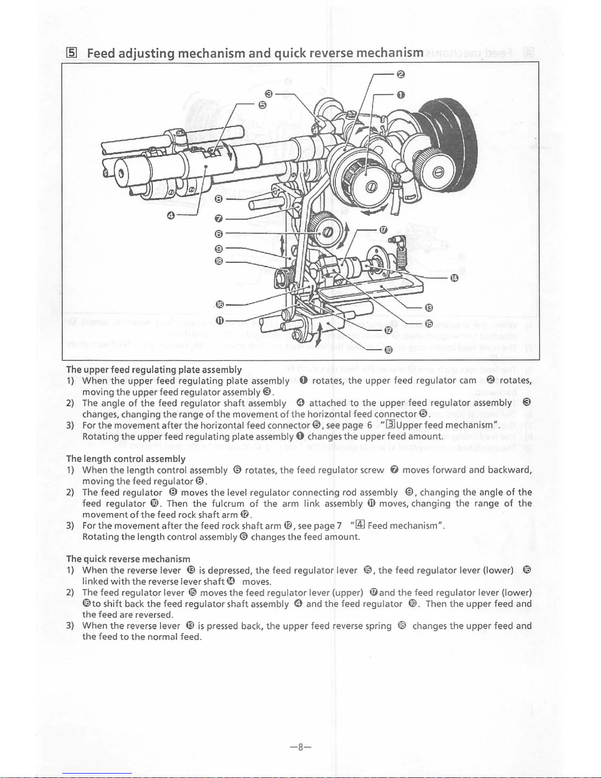
~
Feed adjusting mechanism and quick reverse mechanism
The
upper
feed regulating plate assembly
1)
When
the
upper
feed
regulating
plate
assembly 0 rotates,
the
upper feed regulator
cam
@ rotates,
moving
the
upper
feed
regulator
assembly@.
2)
The angle
of
the
feed
regulator
shaft assembly e attached
to
the
upper
feed
regulator
assembly @
changes, changing
the
range
of
the
movement
of
the horizo
ntal feed
connector@.
3)
For
the
movement
after
the
horizontal feed
connector@,
see
page 6
"[21
Upper feed mechanism
II.
Rotating
the
upper
feed regula
ting
plate assembly 0 changes
the
upper feed amount.
The
length
control assembly
1)
When
the
length
control assembly @ rotates,
the
feed regulator screw
fJ
moves
forward
and backward,
moving
the
feed
regulator@
.
2)
The feed regulator @ moves
the
level
regulator
connecting rod assembly
@,
changing
the
angle
of
the
feed
regulator
@.
Then
the
fulcrum
of
the
arm
lin
k assembly
ID
move
s,
changing
the
range
of
the
movement
of
the
feed rock shaft arm
®.
3)
For
the
movement
after
the
feed rock
shaft
arm
®,
see
page 7
"~
Feed
mechanism
11
•
Rotating
the
length
control assembly@ changes
the
feed amount.
The quick reverse mechanism
1)
When
the
reverse lever ®
is
depressed,
the
feed regul
ator
lever
@,the
feed
regulator
lever (lower) ®
linked
with
the
reverse lever shaft
ID
moves.
2)
The feed
regulator
lever
@moves
the
feed
regulator
lever (upper) {!)and
the
feed
regulator
lever (lower)
®to shift
back
the
feed
regulator
sha
ft
assembly e and
the
feed
regulator
@.
Then
the
upper
feed and
the
feed are reversed.
3)
When
the
reverse lever ®
is
pressed back,
the
upper
feed reverse spring ® changes
the
upper
feed and
the
feed
to
the
normal feed.
-8-
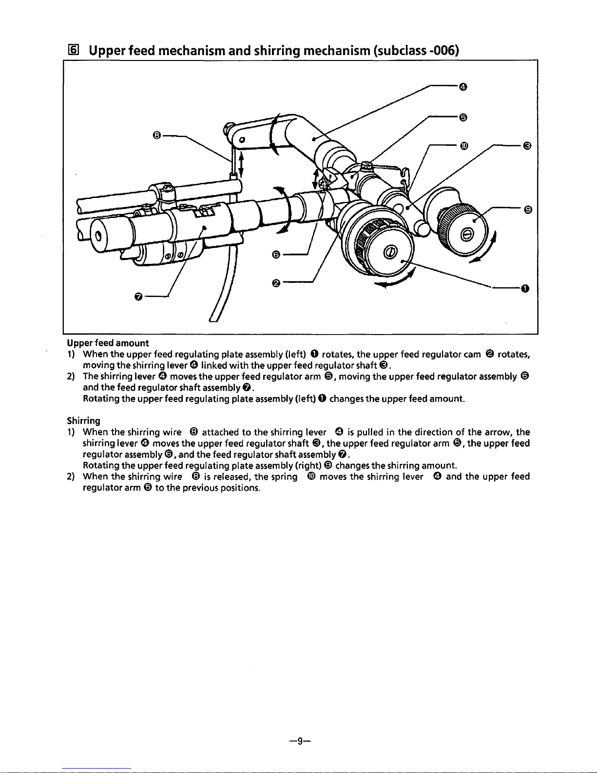
(§]
Upper feed
mechanism
and
shirring
mechanism
(subclass
-006)
Upper feed amount
1)
When
the
upper feed regulating plate assembly (left) 0 rotates, the upper feed regulator
cam
@ rotates,
moving the shirring lever
e linked
with
the
upper feed regulator shaft@.
2)
The shirring lever 9 moves the upper feed regulator arm @),moving the upper feed regulator assembly @
and
the
feed regulator shaft assembly
e.
Rotating the upper feed regulating plate assembly (left) 0 changes
the
upper feed amount.
Shirring
1)
When
the
shirring
wire
@ attached
to
the shirring lever 9
is
pulled in
the
direction
of
the arrow,
the
shirring lever 9 moves
the
upper feed regulator
shaft@,
the upper feed regulator arm
@,the
upper feed
regulator
assembly@, and
the
feed regulator shaft assembly
6.
Rotating the upper feed regulating plate assembly (right)@) changes
the
shirring amount.
2)
When
the
shirring
wire @ is
released,
the
spring
([.i)
moves
the
shirring lever 9 and
the
upper feed
regulator
arm@)
to
the previous positions.
-9-
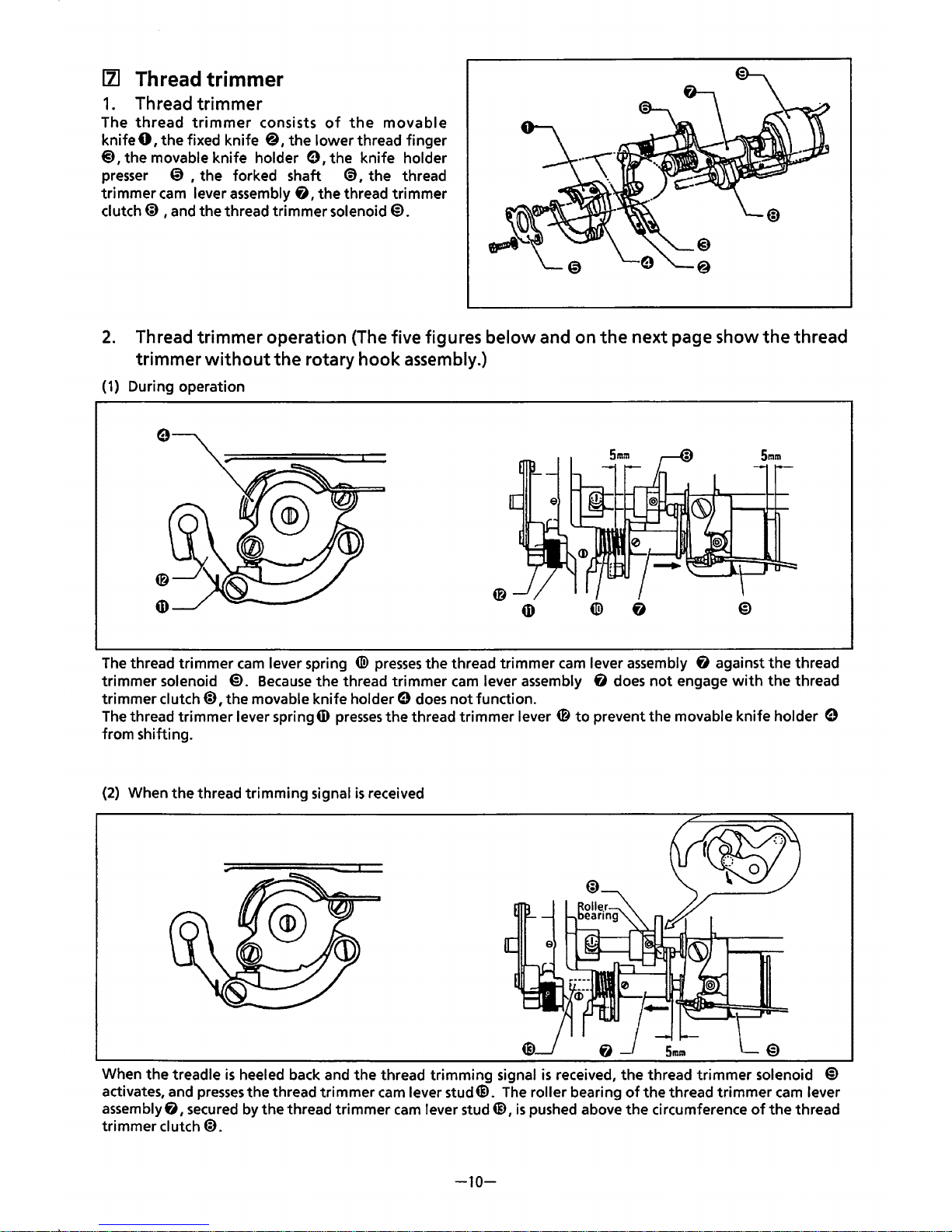
111
Thread trimmer
1.
Thread
trimmer
The
thread
trimmer
consists
of
the
movable
knife
0,
the
fixed knife
@,the
lower
thread finger
@)
1 the movable knife holder e I the knife holder
presser
@ , the forked shaft
@),
the
thread
trimmer
cam
lever assembly
f),
the
thread
trimmer
clutch@ , and the thread trimmer solenoid@.
2.
Thread
trimmer
operation (The five figures
below
and on
the
next page show
the
thread
trimmer
without
the
rotary
hook
assembly.)
(1)
During operation
The
thread trimmer
cam
lever spring @
presses
the thread trimmer
cam
lever assembly
f)
against
the
thread
trimmer
solenoid @.
Because
the
thread trimmer
cam
lever assembly
f)
does
not
engage
with
the
thread
trimmer clutch@ I
the
movable knife holder e
does
not
function.
The
thread trimmer lever springiD
presses
the
thread trimmer lever 0
to
prevent the movable knife holder 9
from shifting.
(2)
When
the
thread trimming signal
is
received
When
the
treadle
is
heeled back and the thread trimming signal
is
received,
the
thread
trimmer
solenoid @
activates, and
presses
the
thread trimmer
cam
lever stud
6).
The
roller bearing
of
the thread trimmer
cam
lever
assembly
f),
secured by
the
thread trimmer
cam
lever stud
6),
is
pushed above
the
circumference
of
the
thread
trimmer
clutch
«D.
-10-
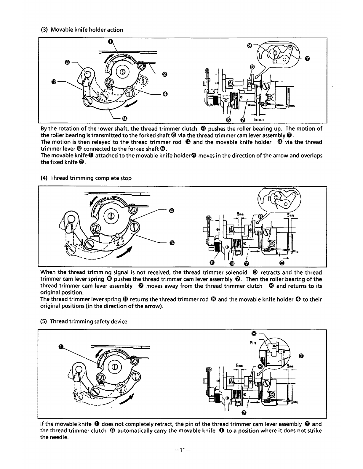
(3)
Movable knife holder action
By
the rotation
of
the lower shaft, the thread trimmer clutch @
pushes
the roller bearing up.
The
motion
of
the roller bearing
is
transmitted
to
the forked shaft@ via the thread trimmer
cam
lever assembly
f).
The
motion
is
then relayed
to
the
thread trimmer rod
49
and the movable knife holder 0 via
the
thread
trimmer lever
4!1
connected
to
the forked shaft@.
The
movable
knifeO
attached
to
the movable knife hold
ere
moves
in the direction
of
the arrow and overlaps
the fixed knife
@.
(4)
Thread trimming complete stop
When the thread trimming signal
is
not
received, the thread trimmer solenoid @ retracts and
the
thread
trimmer
cam
lever spring
tiD
pushes
the thread trimmer
cam
lever assembly
f).
Then
the roller bearing
of
the
thread trimmer
cam
lever assembly
f)
moves away from the thread trimmer clutch @ and returns
to
its
original position.
The
thread trimmer lever spring
4D
returns
the
thread trimmer rod
49
and
the movable knife holder 0
to
their
original positions (in the direction
of
the arrow).
(S)
Thread trimming safety device
If
the movable knife 0
does
not
completely retract,
the
pin
of
the thread trimmer
cam
lever assembly
f)
and
the thread trimmer clutch
@ automatically carry
the
movable knife 0
to
a position where
it
does
not
strike
the needle.
-11-
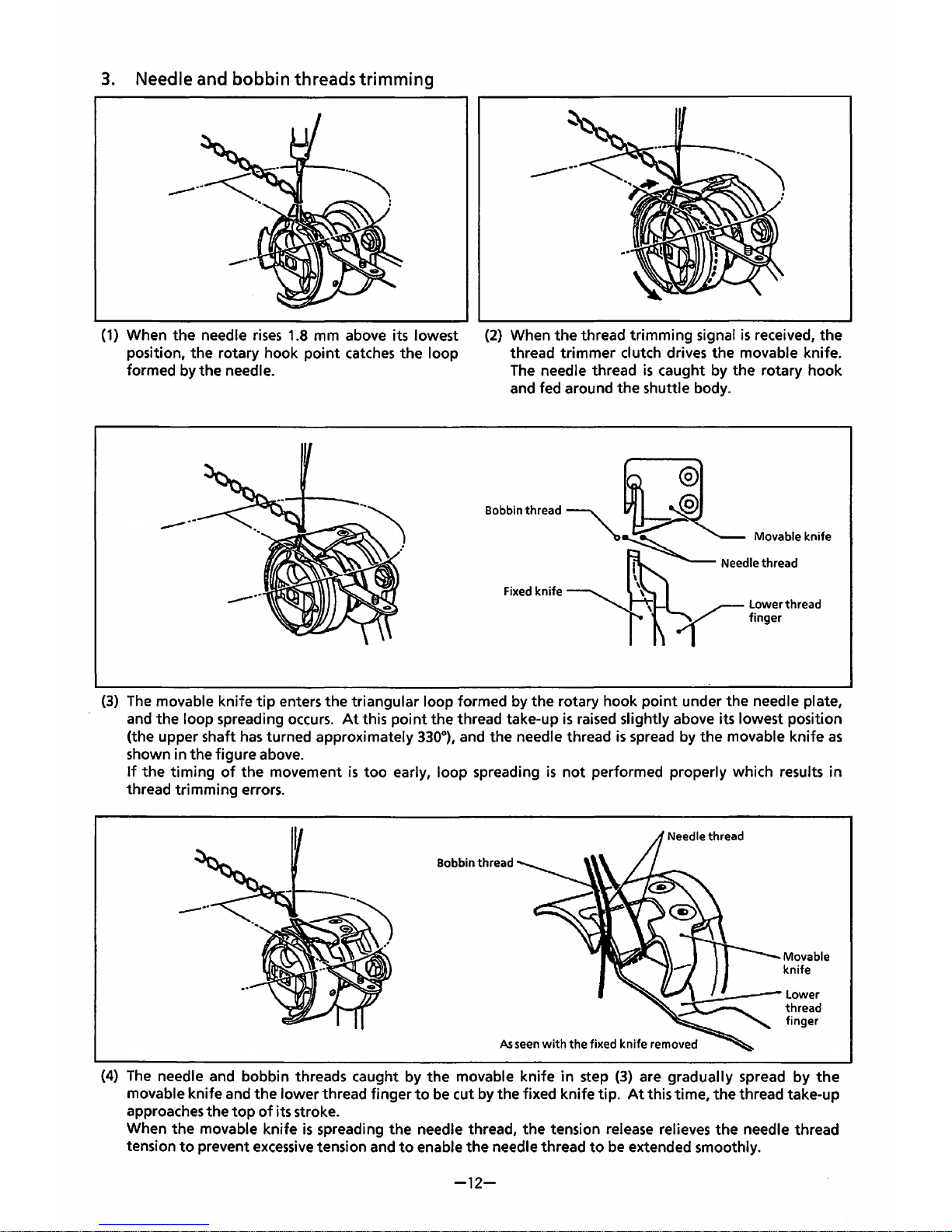
3.
Needle and bobbin threads trimming
(1)
When the needle
rises
1.8
mm above its lowest
position, the rotary hook
point
catches
the loop
formed by the needle.
-----
------
(2)
When the thread trimming signal
is
received, the
thread trimmer
clutch drives the movable knife.
The
needle thread
is
caught by the rotary hook
and fed around the shuttle body.
(3)
The
movable knife
tip
enters the triangular loop formed by the rotary hook point under the needle plate,
and the loop spreading
occurs.
At
this
point
the thread take-up
is
raised
slightly above its lowest position
(the upper shaft
has
turned approximately
330°),
and the needle thread
is
spread by
the
movable knife
as
shown in the figure above.
If
the
timing
of
the movement
is
too
early, loop spreading
is
not
performed properly which results in
thread trimming errors.
Bobbin thread
As
seen
with
the fixed knife removed
Movable
knife
(4)
The
needle and bobbin threads caught by the movable knife in step
(3)
are gradually spread by
the
movable knife and the lower thread finger
to
be
cut by the fixed knife tip.
At
this time, the thread take-up
approaches the
top
of
its stroke.
When the movable knife
is
spreading the needle thread, the tension release relieves
the
needle thread
tension
to
prevent
excessive
tension and
to
enable the needle thread
to
be
extended smoothly.
-12-
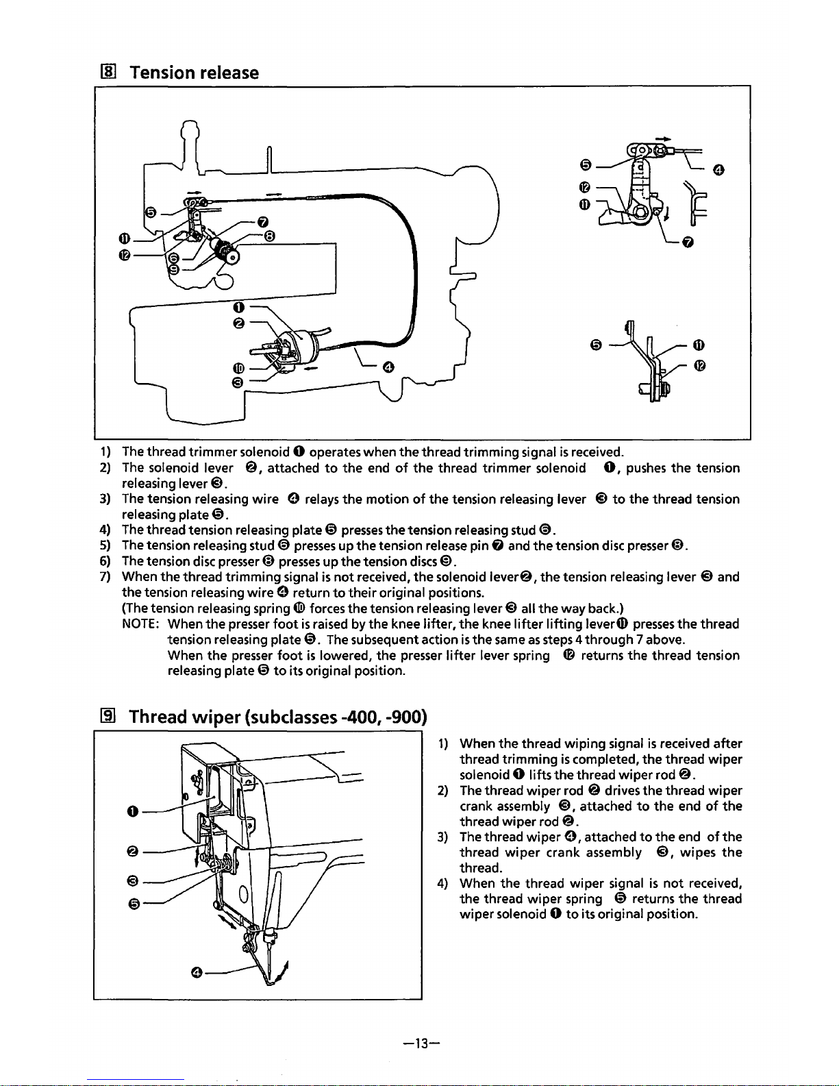
liD
Tension release
1)
The
thread trimmer solenoid 0 operates when the thread trimming signal
is
received.
2)
The
solenoid lever
@,
attached
to
the
end
of
the
thread trimmer solenoid
0,
pushes
the
tension
releasing
lever@.
3)
The
tension releasing wire 0 relays the motion
of
the tension releasing lever
@to
the thread tension
releasing
plate@.
4)
The
thread tension releasing plate@
presses
the tension releasing stud
@.
5)
The
tension releasing stud@
presses
up the tension release pin
fj
and
the
tension
disc
presser@).
6)
The
tension disc
presser@)
presses
up
the
tension
discs@).
7) When the thread trimming signal
is
not
received,
the
solenoid lever@, the tension releasing
lever@
and
the tension releasing wire
0 return
to
their
original positions.
(The
tension releasing spring
4D>
forces the tension releasing lever@ all
the
way back.)
NOTE:
When the
presser
foot
is
raised by the knee lifter,
the
knee
lifter
lifting
lever
G)
presses
the
thread
tension releasing
plate@.
The
subsequent action
is
the
same
as
steps
4 through 7 above.
When the
presser
foot
is
lowered, the presser
lifter
lever spring 0 returns the thread tension
releasing
plate@
to
its original position.
m:J
Thread
wiper
(subclasses -400, -900)
0
1)
When the thread wiping signal
is
received after
thread trimming
is
completed, the thread wiper
solenoid
0 lifts the thread wiper rod@.
2)
The
thread
wiper
rod @ drives the thread wiper
crank assembly
@,
attached
to
the end
of
the
thread wiper rod
@.
3)
The
thread
wiper
0,
attached
to
the
end
of
the
thread
wiper
crank assembly @, wipes
the
thread.
4)
When the thread wiper signal
is
not
received,
the thread
wiper
spring @ returns the thread
wiper solenoid
0
to
its original position.
-13-
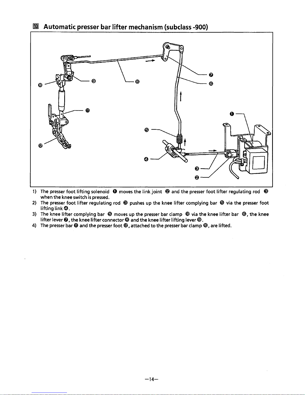
I1W
Automatic
presser
bar lifter
mechanism
(subclass
-900)
t
1)
The
presser
foot
lifting
solenoid 0 moves the
link
joint
@ and the presser
foot
lifter
regulating rod @
when
the
knee switch
is
pressed.
2)
The
presser
foot
lifter
regulating rod @
pushes
up
the
knee
lifter
complying bar
@)
via the presser
foot
lifting
link
9.
3)
The
knee
lifter
complying bar
@)
moves up the presser bar clamp
4ID
via
the
knee
lifter
bar
€)
1
the
knee
lifter
lever & I
the
knee
lifter
connector@) and
the
knee
lifter
lifting
lever
€>.
4)
The
presser bar
0)
and the presser
foot
4fl
1
attached
to
the
presser bar clamp
(@I
are lifted.
-14-
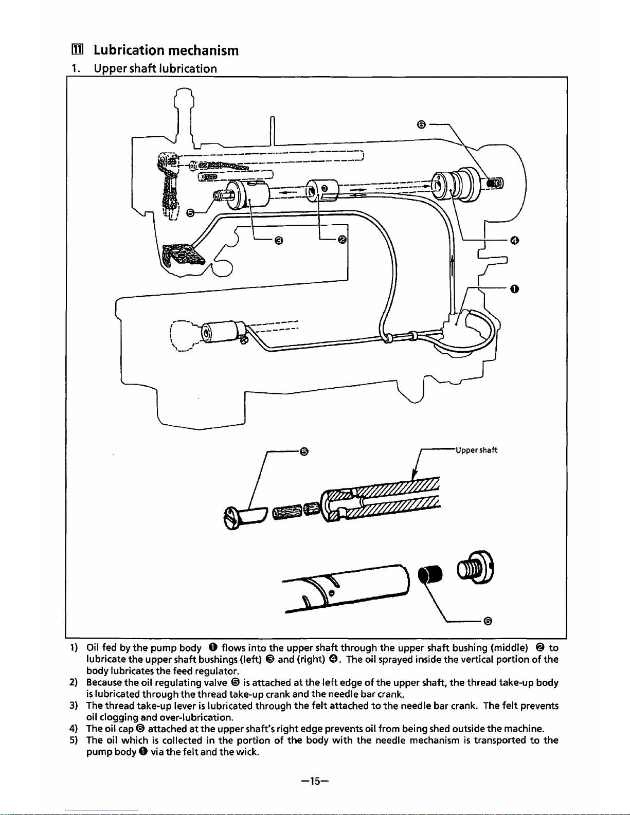
lD1
Lubrication
mechanism
1.
Upper shaft lubrication
1)
Oil fed by the pump body 0 flows
into
the upper shaft through the upper shaft bushing (middle) @
to
lubricate the upper shaft bushings (left) @ and (right)
9.
The
oil sprayed inside the vertical portion
of
the
body lubricates the feed regulator.
2)
Because
the oil regulating valve ~ is
attached
at
the
left
edge
of
the upper shaft, the thread take-up body
is
lubricated through the thread take-up crank and the needle bar crank.
3)
The
thread take-up lever
is
lubricated through the
felt
attached
to
the needle bar crank.
The
felt
prevents
oil clogging and over-lubrication.
4)
The
oil cap@ attached
at
the
upper shaft's right edge prevents oil from being
shed
outside
the
machine.
5)
The
oil which
is
collected in the portion
of
the
body
with
the needle mechanism
is
transported
to
the
pump body 0 via the
felt
and the wick.
-15-
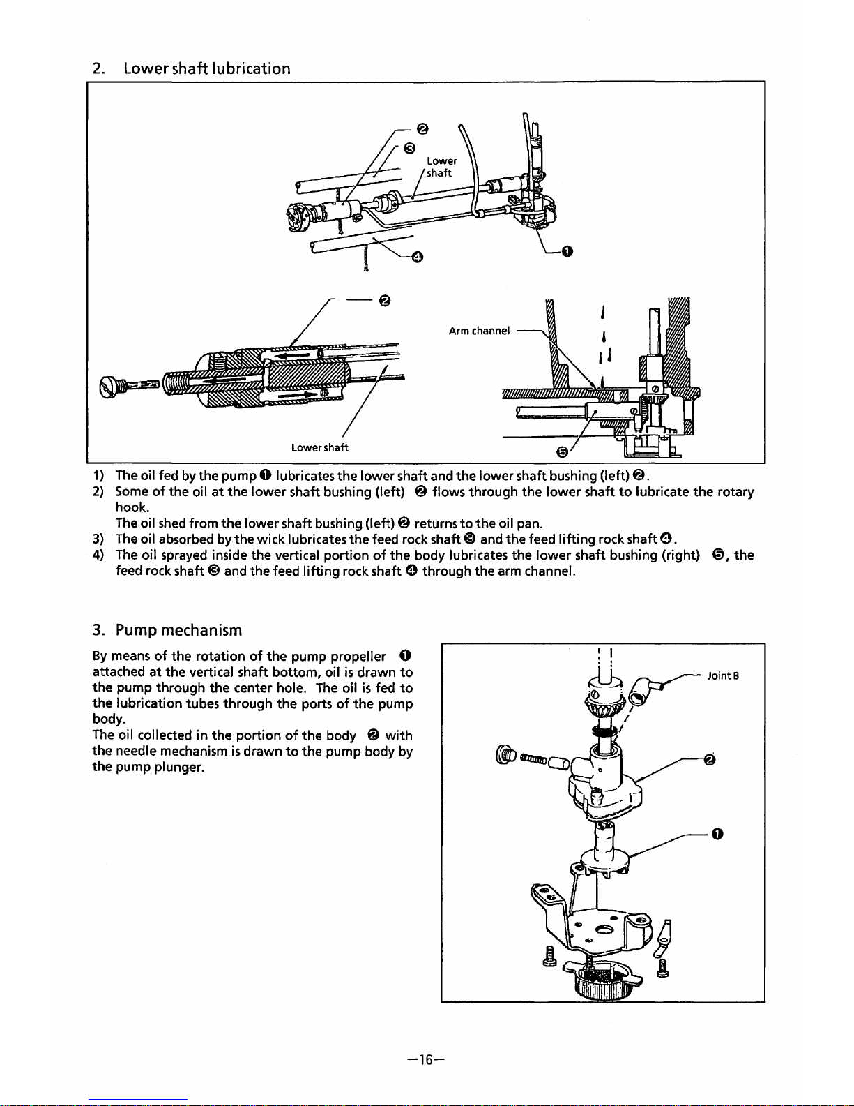
2.
Lower shaft lubrication
0
Arm channel
Lower shaft
1)
The
oil fed
by
the pump 0 lubricates the lower shaft and the lower shaft bushing (left)@.
2)
Some
of
the oil
at
the
lower shaft bushing (left) @ flows through the lower shaft
to
lubricate
the
rotary
hook.
The
oil
shed
from the lower shaft bushing (left)@ returns
to
the oil pan.
3)
The
oil absorbed by the wick lubricates the feed rock shaft@ and the feed
lifting
rock shaft
e.
4)
The
oil sprayed inside the vertical portion
of
the body lubricates the lower shaft bushing (right)
8,
the
feed rock
shaft@ and the feed
lifting
rock shaft e through the arm channel.
3.
Pump mechanism
By
means
of
the rotation
of
the pump propeller 0
attached
at
the vertical shaft bottom, oil
is
drawn
to
the pump through the center hole.
The
oil
is
fed
to
the lubrication tubes through the ports
of
the pump
body.
The
oil collected in the portion
of
the body @
with
the needle mechanism
is
drawn
to
the pump body by
the pump
plunger.
-16-
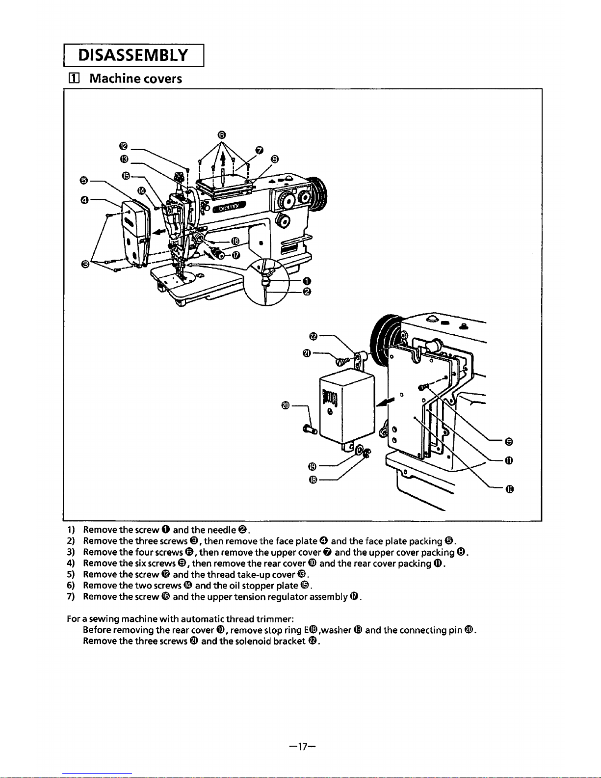
DISASSEMBLY
[]]
Machine covers
1)
Remove
the
screw 0 and
the
needle@.
2)
Remove
the
three screws@), then remove
the
face plate e and
the
face plate packing@.
3)
Remove
the
four
screws@,
then
remove
the
upper cover
fl
and
the
upper cover packing@.
4)
Remove
the
six screws@),
then
remove
the
rear cover
4ID
and
the
rear cover packing {I).
5)
Remove
the
screw@ and
the
thread take-up cover@.
6)
Remove
the
two
screws
49
and
the
oil stopper
plate®.
7)
Remove
the
screw(;) and
the
upper tension regulator assembly
49.
For a sewing machine
with
automatic thread
trimmer:
Before removing
the
rear cover
4ID,
remove stop ring E® ,washer@ and
the
connecting pin
W.
Remove
the
three screws ~ and
the
solenoid bracket
fD.
-17-
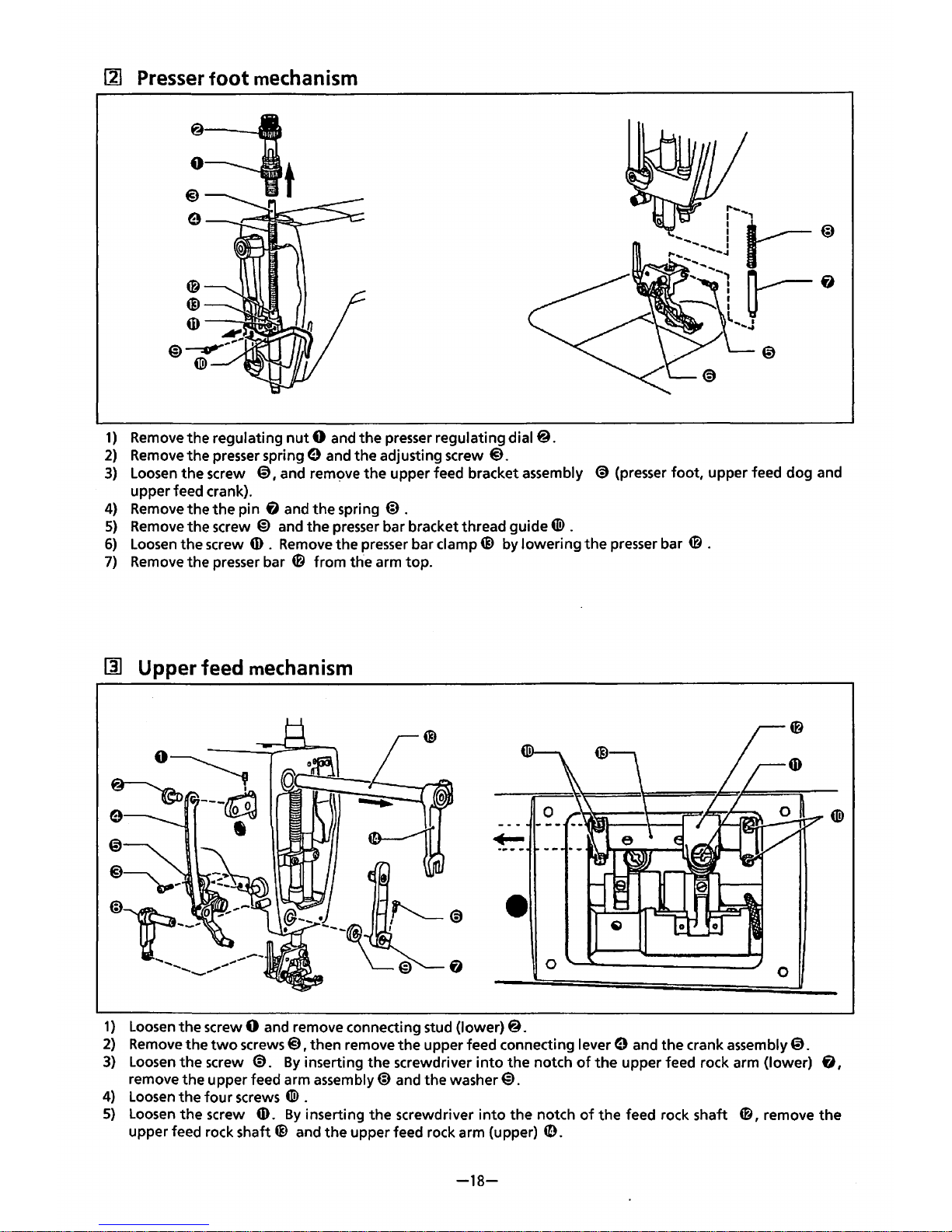
111
Presser
foot
mechanism
1)
Remove
the regulating
nut
0 and
the
presser
regulating
dial@.
2)
Remove
the presser spring 9 and the adjusting screw
@).
3)
Loosen
the
screw @, and
rem~:>Ve
the
upper feed bracket assembly
@)
(presser foot, upper feed dog and
upper feed crank).
4)
Remove
the
the
pin 6 and the spring @ .
5)
Remove
the screw @ and
the
presser
bar bracket thread guide
4ID
.
6)
Loosen
the
screw
ID
.
Remove
the presser bar clamp@ by lowering
the
presser bar 0 .
7)
Remove
the presser bar 0 from the arm top.
llJ
Upper feed
mechanism
0
0
1)
Loosen
the
screw 0 and remove connecting stud (lower)@.
2)
Remove
the
two
screws@),
then remove
the
upper feed connecting lever 9 and the crank assembly@.
3)
Loosen
the screw
@).
By
inserting
the
screwdriver
into
the notch
of
the
upper feed rock arm (lower) & ,
remove
the
upper feed arm assembly@ and the washer@).
4)
Loosen
the
four
screws
4ID
.
5)
Loosen
the
screw (D.
By
inserting the screwdriver
into
the notch
of
the feed rock shaft
0,
remove
the
upper feed rock
shaft~
and
the
upper feed rock arm (upper)
~.
-18-
 Loading...