

Page 1

53-1003147-01
27 June 2014
Monitoring and Alerting
Policy Suite
Administrator's Guide
Supporting Fabric OS v7.3.0
Page 2

©
2014, Brocade Communications Systems, Inc. All Rights Reserved.
Brocade, the B-wing symbol, Brocade Assurance, ADX, AnyIO, DCX, Fabric OS, FastIron, HyperEdge, ICX, MLX, MyBrocade, NetIron,
OpenScript, VCS, VDX, and Vyatta are registered trademarks, and The Effortless Network and the On-Demand Data Center are trademarks
of Brocade Communications Systems, Inc., in the United States and in other countries. Other brands and product names mentioned may be
trademarks of others.
Notice: This document is for informational purposes only and does not set forth any warranty, expressed or implied, concerning any
equipment, equipment feature, or service offered or to be offered by Brocade. Brocade reserves the right to make changes to this document
at any time, without notice, and assumes no responsibility for its use. This informational document describes features that may not be
currently available. Contact a Brocade sales office for information on feature and product availability. Export of technical data contained in
this document may require an export license from the United States government.
The authors and Brocade Communications Systems, Inc. assume no liability or responsibility to any person or entity with respect to the
accuracy of this document or any loss, cost, liability, or damages arising from the information contained herein or the computer programs that
accompany it.
The product described by this document may contain open source software covered by the GNU General Public License or other open
source license agreements. To find out which open source software is included in Brocade products, view the licensing terms applicable to
the open source software, and obtain a copy of the programming source code, please visit http://www.brocade.com/support/oscd.
Page 3

Contents
Preface.....................................................................................................................................7
Document conventions......................................................................................7
Text formatting conventions.................................................................. 7
Command syntax conventions.............................................................. 7
Notes, cautions, and warnings.............................................................. 8
Brocade resources............................................................................................ 9
Contacting Brocade Technical Support.............................................................9
Document feedback........................................................................................ 10
About This Document.............................................................................................................. 11
Supported hardware and software.................................................................. 11
What's new in this document...........................................................................12
Monitoring and Alerting Policy Suite Overview .........................................................................13
MAPS overview ..............................................................................................13
MAPS license requirements............................................................................14
MAPS configuration files................................................................................. 14
Deleting a user-created MAPS configuration file................................ 14
MAPS interoperability with other features....................................................... 14
Restrictions on MAPS monitoring................................................................... 15
Firmware upgrade and downgrade considerations for MAPS.........................15
Firmware upgrade considerations.......................................................15
Firmware downgrade considerations.................................................. 16
Fabric Watch to MAPS migration ................................................................... 16
Differences between Fabric Watch and MAPS configurations............17
MAPS Setup and Operation.....................................................................................................19
Initial MAPS setup...........................................................................................19
Monitoring across different time windows....................................................... 21
Setting the active MAPS policy....................................................................... 22
Pausing MAPS monitoring.............................................................................. 23
Resuming MAPS monitoring........................................................................... 23
MAPS Elements and Categories ..............................................................................................25
MAPS structural elements...............................................................................25
MAPS monitoring categories ..........................................................................25
Monitoring and Alerting Policy Suite Administrator's Guide
53-1003147-01
Enabling MAPS using Fabric Watch rules.......................................... 19
Enabling MAPS without using Fabric Watch rules.............................. 20
Port Health.......................................................................................... 26
FRU Health......................................................................................... 27
Security Violations ..............................................................................28
Fabric State Changes......................................................................... 29
Switch Resource ................................................................................ 30
Traffic Performance.............................................................................31
FCIP Health ........................................................................................32
Fabric Performance Impact.................................................................32
3
Page 4

Switch Policy Status..........................................................................33
MAPS Groups, Policies, Rules, and Actions............................................................................35
MAPS groups overview.................................................................................35
Viewing group information ................................................................35
Predefined groups.............................................................................36
User-defined groups..........................................................................38
Cloning a group.................................................................................41
Deleting groups.................................................................................41
Restoring group membership............................................................42
MAPS policies overview................................................................................43
Predefined policies............................................................................44
User-defined policies.........................................................................44
Fabric Watch legacy policies.............................................................45
Working with MAPS policies ............................................................ 45
MAPS conditions...........................................................................................49
Threshold values...............................................................................50
Time base......................................................................................... 50
MAPS rules overview....................................................................................50
MAPS rule actions.............................................................................50
Working with MAPS rules and actions.............................................. 56
Port Monitoring Using MAPS................................................................................................. 65
Port monitoring and pausing......................................................................... 65
Monitoring similar ports using the same rules...............................................65
Port monitoring using port names................................................................. 66
Port monitoring using device WWNs ............................................................66
Adding a port to an existing group................................................................ 66
Adding missing ports to a group .................................................................. 67
Removing ports from a group........................................................................68
D_Port monitoring......................................................................................... 68
Monitoring Flow Vision Flows with MAPS............................................................................... 71
Viewing Flow Vision Flow Monitor data with MAPS......................................71
Flow Vision statistics supported by MAPS........................................71
Restrictions on Flow Vision flow monitoring......................................72
Removing flows from MAPS............................................................. 72
Sub-flow monitoring and MAPS........................................................ 73
Examples of using MAPS to monitor traffic performance............................. 73
Examples of monitoring flows at the sub-flow level...................................... 74
MAPS Dashboard .................................................................................................................75
MAPS dashboard overview...........................................................................75
MAPS dashboard period display options.......................................... 75
Clearing data.....................................................................................75
MAPS dashboard sections............................................................................76
Notes on dashboard data..................................................................78
Viewing the MAPS dashboard...................................................................... 78
Viewing a summary switch status report...........................................79
Viewing a detailed switch status report.............................................81
Viewing historical data...................................................................... 83
Viewing data for a specific time window ...........................................83
4
Monitoring and Alerting Policy Suite Administrator's Guide
53-1003147-01
Page 5

Additional MAPS Features.......................................................................................................85
Fabric performance monitoring using MAPS.................................................. 85
Enabling MAPS Fabric Performance Impact monitoring.....................86
Bottleneck detection with the MAPS dashboard ................................ 86
MAPS Fabric Performance Impact monitoring and legacy
bottleneck monitoring.................................................................... 88
Scalability limit monitoring...............................................................................88
Layer 2 fabric device connection monitoring.......................................89
Imported LSAN device connection monitoring in a metaSAN.............89
Backbone fabric Fibre Channel router count monitoring.....................89
Zone configuration size monitoring..................................................... 90
Scalability limit monitoring assumptions and dependencies............... 90
Default rules for scalability limit monitoring......................................... 91
Examples of scalability limit rules........................................................91
MAPS Service Availability Module.................................................................. 92
Brocade 7840 FCIP monitoring using MAPS.................................................. 94
MAPS Threshold Values...........................................................................................................97
Viewing monitoring thresholds........................................................................ 97
Fabric monitoring thresholds...........................................................................98
FCIP monitoring thresholds.............................................................................99
FRU state thresholds.................................................................................... 100
Port Health monitoring thresholds.................................................................100
Resource monitoring thresholds................................................................... 107
Security monitoring thresholds......................................................................108
SFP monitoring thresholds............................................................................109
Fabric Performance Impact thresholds......................................................... 110
Switch Status Policy thresholds.................................................................... 110
Traffic Performance thresholds..................................................................... 113
Monitoring and Alerting Policy Suite Administrator's Guide
53-1003147-01
5
Page 6

6 Monitoring and Alerting Policy Suite Administrator's Guide
53-1003147-01
Page 7

Preface
● Document conventions......................................................................................................7
● Brocade resources............................................................................................................ 9
● Contacting Brocade Technical Support.............................................................................9
● Document feedback........................................................................................................ 10
Document conventions
The document conventions describe text formatting conventions, command syntax conventions, and
important notice formats used in Brocade technical documentation.
Text formatting conventions
Text formatting conventions such as boldface, italic, or Courier font may be used in the flow of the text
to highlight specific words or phrases.
Format
bold text
italic text
Courier font
Description
Identifies command names
Identifies keywords and operands
Identifies the names of user-manipulated GUI elements
Identifies text to enter at the GUI
Identifies emphasis
Identifies variables and modifiers
Identifies paths and Internet addresses
Identifies document titles
Identifies CLI output
Identifies command syntax examples
Command syntax conventions
Bold and italic text identify command syntax components. Delimiters and operators define groupings of
parameters and their logical relationships.
Convention
bold text Identifies command names, keywords, and command options.
italic text Identifies a variable.
Description
Monitoring and Alerting Policy Suite Administrator's Guide 7
53-1003147-01
Page 8
Notes, cautions, and warnings
Convention Description
value In Fibre Channel products, a fixed value provided as input to a command
[ ] Syntax components displayed within square brackets are optional.
option is printed in plain text, for example, --show WWN.
Default responses to system prompts are enclosed in square brackets.
{ x | y | z } A choice of required parameters is enclosed in curly brackets separated by
x | y A vertical bar separates mutually exclusive elements.
< > Nonprinting characters, for example, passwords, are enclosed in angle
...
\
vertical bars. You must select one of the options.
In Fibre Channel products, square brackets may be used instead for this
purpose.
brackets.
Repeat the previous element, for example, member[member...].
Indicates a “soft” line break in command examples. If a backslash separates
two lines of a command input, enter the entire command at the prompt without
the backslash.
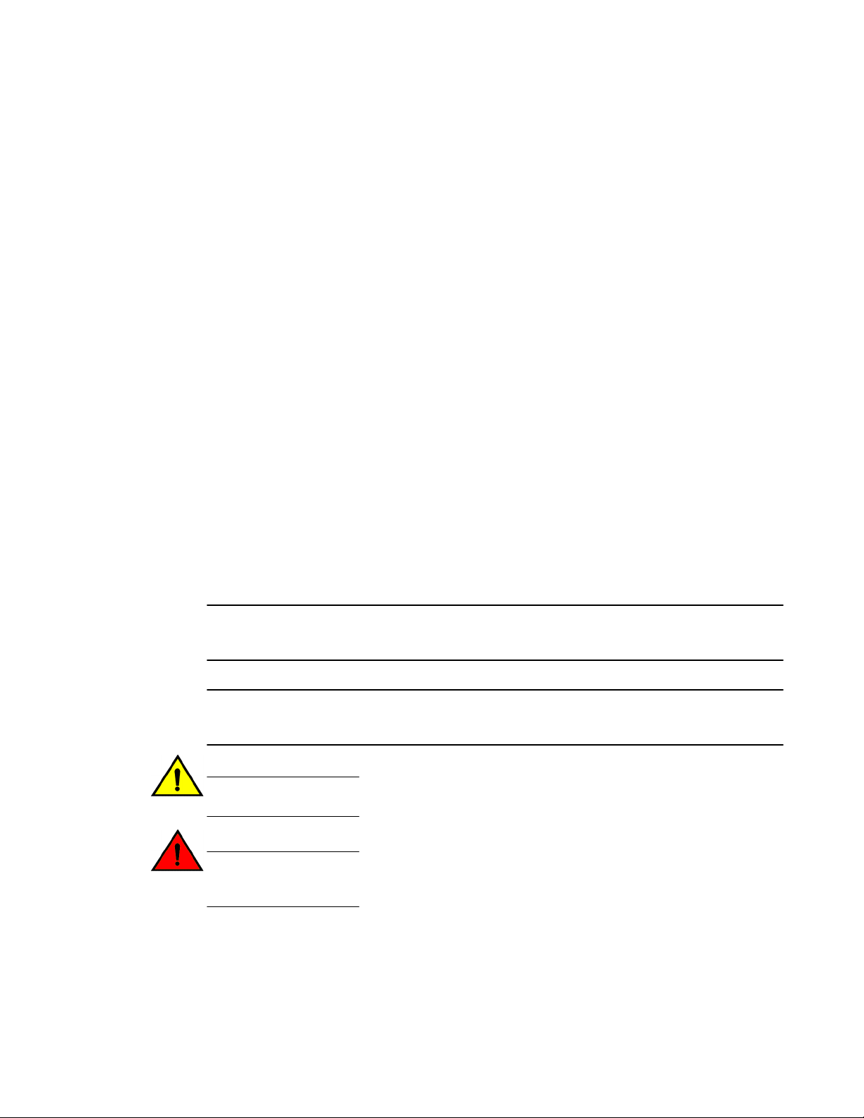
Notes, cautions, and warnings
Notes, cautions, and warning statements may be used in this document. They are listed in the order of
increasing severity of potential hazards.
NOTE
A Note provides a tip, guidance, or advice, emphasizes important information, or provides a reference
to related information.
ATTENTION
An Attention statement indicates a stronger note, for example, to alert you when traffic might be
interrupted or the device might reboot.
CAUTION
A Caution statement alerts you to situations that can be potentially hazardous to you or cause
damage to hardware, firmware, software, or data.
DANGER
A Danger statement indicates conditions or situations that can be potentially lethal or
extremely hazardous to you. Safety labels are also attached directly to products to warn of
these conditions or situations.
8 Monitoring and Alerting Policy Suite Administrator's Guide
53-1003147-01
Page 9

Brocade resources
Visit the Brocade website to locate related documentation for your product and additional Brocade
resources.
You can download additional publications supporting your product at www.brocade.com. Select the
Brocade Products tab to locate your product, then click the Brocade product name or image to open the
individual product page. The user manuals are available in the resources module at the bottom of the
page under the Documentation category.
To get up-to-the-minute information on Brocade products and resources, go to MyBrocade. You can
register at no cost to obtain a user ID and password.
Release notes are available on MyBrocade under Product Downloads.
White papers, online demonstrations, and data sheets are available through the Brocade website.
Contacting Brocade Technical Support
Brocade resources
As a Brocade customer, you can contact Brocade Technical Support 24x7 online, by telephone, or by email. Brocade OEM customers contact their OEM/Solutions provider.
Brocade customers
For product support information and the latest information on contacting the Technical Assistance
Center, go to http://www.brocade.com/services-support/index.html.
If you have purchased Brocade product support directly from Brocade, use one of the following methods
to contact the Brocade Technical Assistance Center 24x7.
Online Telephone E-mail
Preferred method of contact for nonurgent issues:
• My Cases through MyBrocade
• Software downloads and licensing
tools
• Knowledge Base
Required for Sev 1-Critical and Sev
2-High issues:
• Continental US: 1-800-752-8061
• Europe, Middle East, Africa, and
Asia Pacific: +800-AT FIBREE
(+800 28 34 27 33)
• For areas unable to access toll
free number: +1-408-333-6061
• Toll-free numbers are available in
many countries.
support@brocade.com
Please include:
• Problem summary
• Serial number
• Installation details
• Environment description
Brocade OEM customers
If you have purchased Brocade product support from a Brocade OEM/Solution Provider, contact your
OEM/Solution Provider for all of your product support needs.
• OEM/Solution Providers are trained and certified by Brocade to support Brocade® products.
• Brocade provides backline support for issues that cannot be resolved by the OEM/Solution Provider.
Monitoring and Alerting Policy Suite Administrator's Guide 9
53-1003147-01
Page 10

Document feedback
• Brocade Supplemental Support augments your existing OEM support contract, providing direct
access to Brocade expertise. For more information, contact Brocade or your OEM.
• For questions regarding service levels and response times, contact your OEM/Solution Provider.
Document feedback
To send feedback and report errors in the documentation you can use the feedback form posted with
the document or you can e-mail the documentation team.
Quality is our first concern at Brocade and we have made every effort to ensure the accuracy and
completeness of this document. However, if you find an error or an omission, or you think that a topic
needs further development, we want to hear from you. You can provide feedback in two ways:
• Through the online feedback form in the HTML documents posted on www.brocade.com.
• By sending your feedback to documentation@brocade.com.
Provide the publication title, part number, and as much detail as possible, including the topic heading
and page number if applicable, as well as your suggestions for improvement.
10 Monitoring and Alerting Policy Suite Administrator's Guide
53-1003147-01
Page 11

About This Document
● Supported hardware and software.................................................................................. 11
● What's new in this document...........................................................................................12
Supported hardware and software
In those instances in which procedures or parts of procedures documented here apply to some switches
but not to others, this list identifies exactly which switches are supported and which are not.
Although many different software and hardware configurations are tested and supported by Brocade
Communications Systems, Inc. for Fabric OS 7.3.0, documenting all possible configurations and
scenarios is beyond the scope of this document.
The following hardware platforms are supported by this release of Fabric OS:
Brocade Fixed-port switchesTABLE 1
Gen 4 platform (8-Gpbs) Gen 5 platform (16-Gbps)
Brocade 300 switch Brocade 6505 switch
Brocade 5100 switch Brocade M6505 embedded switch
Brocade 5300 switch Brocade 6510 switch
Brocade 5410 embedded switch Brocade 6520 switch
Brocade 5424 embedded switch Brocade 6547 embedded switch
Brocade 5430 embedded switch Brocade 6548 embedded switch
Brocade 5431 embedded switch Brocade 7840 extension switch
Brocade 5432 embedded switch
Brocade 5450 embedded switch
Brocade 5460 embedded switch
Brocade 5470 embedded switch
Brocade 5480 embedded switch
Brocade NC-5480 embedded switch
Brocade 7800 extension switch
Brocade VA-40FC
Brocade Encryption Switch
Monitoring and Alerting Policy Suite Administrator's Guide 11
53-1003147-01
Page 12

What's new in this document
Brocade DCX Backbone familyTABLE 2
Gen 4 platform (8-Gpbs) Gen 5 platform (16-Gbps)
Brocade DCX Brocade DCX 8510-4
Brocade DCX-4S Brocade DCX 8510-8
What's new in this document
The following content is new or significantly revised for this release of this document:
• Added new options in mapsSam --show command to show specific detail
• Added new options in mapsRule and logicalGroup commands to force changes
• Added new options in mapsConfig command to send test e-mails
• Enhanced D_Port monitoring
• Added new default monitoring groups
• Added new “Port Decommissioning” action
• Added new dynamic user-defined groups and sub-flow monitoring
• Added ability to monitor throughput degradation
• Added ability to monitor device connection scalability limits
• Added ability to monitor switch Ethernet management ports
• Added ability to monitor Brocade 7840 device for tunnel-level QoS
• Added ability to monitor Brocade 7840 device using tunnel-level and circuit parameters
• Revised MAPS and Fabric Performance Impact (bottleneck) monitoring
12 Monitoring and Alerting Policy Suite Administrator's Guide
53-1003147-01
Page 13

Monitoring and Alerting Policy Suite Overview
● MAPS overview ..............................................................................................................13
● MAPS license requirements............................................................................................14
● MAPS configuration files................................................................................................. 14
● MAPS interoperability with other features....................................................................... 14
● Restrictions on MAPS monitoring................................................................................... 15
● Firmware upgrade and downgrade considerations for MAPS.........................................15
● Fabric Watch to MAPS migration ................................................................................... 16
MAPS overview
The Monitoring and Alerting Policy Suite (MAPS) is an optional storage area network (SAN) health
monitor supported on all switches running Fabric OS 7.2.0 or later that allows you to enable each switch
to constantly monitor itself for potential faults and automatically alerts you to problems before they
become costly failures.
MAPS tracks a variety of SAN fabric metrics and events. Monitoring fabric-wide events, ports, and
environmental parameters enables early fault detection and isolation as well as performance
measurements.
MAPS provides a set of predefined monitoring policies that allow you to immediately use MAPS on
activation. Refer to Predefined policies on page 44 for information on using these policies.
In addition, MAPS provides customizable monitoring thresholds. These allow you to configure specific
groups of ports or other elements so that they share a common threshold value. You can configure
MAPS to provide notifications before problems arise, for example, when network traffic through a port is
approaching the bandwidth limit. MAPS lets you define how often to check each switch and fabric
measure and specify notification thresholds. Whenever fabric measures exceed these thresholds,
MAPS automatically provides notification using several methods, including e-mail messages, SNMP
traps, and log entries. Refer to MAPS groups overview on page 35, MAPS rules overview on page
50, and MAPS policies overview on page 43 for information on using these features.
The MAPS dashboard provides you with the ability to view in a quick glance what is happening on the
switch, and helps administrators dig deeper to see details of exactly what is happening on the switch
(for example, the kinds of errors, the error count, and so on). Refer to MAPS dashboard overview on
page 75 for more information.
MAPS provides a seamless migration of all customized Fabric Watch thresholds to MAPS, thus allowing
you to take advantage of the advanced capabilities of MAPS. MAPS provides additional advanced
monitoring, such as monitoring for the same error counters across different time periods, or having
more than two thresholds for any error counters. MAPS also provides support for you to monitor the
statistics provided by the Flow Monitor feature of Flow Vision. Refer to Differences between Fabric
Watch and MAPS configurations on page 17 and Fabric Watch to MAPS migration on page 16 for
details.
Activating MAPS is a chassis-specific process, and you can activate only one chassis at a time. On a
given chassis there can be multiple logical switches. Activating MAPS enables it for all logical switches
in the chassis, however each logical switch can have its own MAPS configuration.
Monitoring and Alerting Policy Suite Administrator's Guide
53-1003147-01
13
Page 14

MAPS license requirements
CAUTION
MAPS activation is a non-reversible process. Downgrading the switch firmware to an earlier
version of Fabric OS will enable Fabric Watch with its last configured settings. If you then reupgrade the switch firmware back to the later version (such as Fabric OS 7.3.0), Fabric Watch
will continue to be enabled.
MAPS automatically monitors the management port (Eth0 or Bond0), as the rule for Ethernet port
monitoring is present in all three default policies. While these cannot be modified, the management
port monitoring rules can be removed from cloned policies. Refer to Predefined policies on page 44
for more information.
MAPS license requirements
The Brocade Monitoring and Alerting Policy Suite (MAPS) is an optionally licensed Fabric OS feature.
MAPS requires an active and valid Fabric Vision license. If you already have a license for Fabric
Watch plus a license for Advanced Performance Monitoring, you will automatically get MAPS
functionality without having to obtain an additional license. Refer to the Fabric OS Software Licensing
Guide for more information about licensing and how to obtain the necessary license keys.
MAPS configuration files
The MAPS configuration is stored in two separate configuration files, one for the default MAPS
configuration and one for the user-created MAPS configuration. Only one user configuration file can
exist for each logical switch. A configuration upload or download affects only the user-created
configuration files. You cannot upload or download the default MAPS configuration file.
Deleting a user-created MAPS configuration file
To remove the user-created MAPS configuration, complete the following steps.
1. Connect to the switch and log in using an account with admin permissions.
2. Enter mapsconfig --purge.
For more information on this command, refer to the Fabric OS Command Reference.
MAPS interoperability with other features
MAPS interacts in different ways with different Fabric OS features, including Virtual Fabrics, Fabric
Watch, High Availability, and Admin Domains.
The following table outlines how MAPS interacts with specific features in Fabric OS.
14 Monitoring and Alerting Policy Suite Administrator's Guide
53-1003147-01
Page 15

Interactions between Fabric OS features and MAPSTABLE 3
Feature MAPS interaction
Restrictions on MAPS monitoring
Virtual Fabrics When using Virtual Fabrics, different logical switches in a chassis can have different MAPS
Fabric Watch MAPS cannot coexist with Fabric Watch. Refer to Fabric Watch to MAPS migration on page
High Availability MAPS configuration settings are maintained across a High Availability (HA) failover or HA
Admin Domains MAPS is supported on switches that have Admin Domains. There can only be one MAPS
configurations.
16 for information on this migration.
reboot; however, MAPS will restart monitoring after a HA failover or HA reboot and the cached
MAPS statistics are not retained.
configuration that is common to all the Admin Domains on the chassis. Users with Administrator
privileges can modify the MAPS configuration from any Admin Domain.
ATTENTION
If MAPS is enabled, do not download configuration files that have Admin Domains defined in
them, as this may cause unpredictable behavior.
Restrictions on MAPS monitoring
The following restrictions apply globally to MAPS monitoring.
• Small form-factor pluggable (SFP) transceivers on simulated mode (SIM) ports cannot be monitored
using MAPS.
• If a SCN pertaining to the FRU (such as PS_FAULTY, or FAN_FAULTY), occurs before the
dashboard starts monitoring then it may not be shown in the dashboard.
Refer to Restrictions on Flow Vision flow monitoring on page 72 for additional restrictions on
monitoring Flow Vision flows.
Firmware upgrade and downgrade considerations for MAPS
The following firmware upgrade and downgrade considerations apply to the Monitoring and Alerting
Policy Suite (MAPS) in Fabric OS 7.3.0.
Firmware upgrade considerations
There are no direct upgrade considerations. However, MAPS Fabric Performance Impact monitoring
and the legacy bottleneck monitoring feature are mutually exclusive. If the legacy bottleneck monitoring
feature was enabled before the upgrade, MAPS will not monitor fabric performance. Refer to Fabric
performance monitoring using MAPS on page 85 for additional information.
Monitoring and Alerting Policy Suite Administrator's Guide 15
53-1003147-01
Page 16

Firmware downgrade considerations
Firmware downgrade considerations
When downgrading from Fabric OS 7.3.0 to any previous version of the operating system, the
following MAPS-related behaviors should be expected:
• When an active Command Processor (CP) is running Fabric OS 7.3.0 or 7.2.0 with MAPS disabled,
and the standby device has an earlier version of Fabric OS, High Availability will be synchronized,
but MAPS will not be allowed to be enabled until the firmware on the standby device is upgraded.
The mapsConfig --enablemaps command fails and an error message is displayed.
• When an active CP is running Fabric OS 7.3.0 or 7.2.0 and MAPS is enabled, but the standby
device is running Fabric OS 7.1.0 or earlier, then High Availability will not be synchronized until the
standby CP is upgraded to Fabric OS 7.3.0 or 7.2.0.
• On devices with a single CP, there is no change in behavior when downgrading to an earlier version
of Fabric OS.
• Downgrading to versions of Fabric OS prior to version 7.3.0 will fail if some features are not
supported in the earlier firmware and their loss could impact MAPS functionality. In this case, MAPS
provides instructions on how to disable these features before firmware downgrade. An example of
this is if either MAPS actions or rules include Fabric Performance Impact monitoring or port
decommissioning. Refer to Port decommissioning and firmware downgrades on page 54 for
additional information.
• Downgrading to versions of Fabric OS prior to version 7.3.0 will trigger a warning message if any
feature is not supported in the earlier firmware and keeping the feature configuration is harmless. In
this case, MAPS provides a warning message similar to the following, but does not block the
downgrade.
WARNING: <A>, <B>, <C> feature(s) is/are enabled. These features are not
available in FOS <a.b.c> release.
Do you want to continue?
Examples of this condition include MAPS having any user-created rules pertaining to monitoring the
following: D_Ports, L2_DEVCNT_PER, LSAN_DEVCNT_PER, ZONE_CFGSZ_PER,
BB_FCR_CNT, or ETH_MGMT_PORT.
• Downgrading to versions of Fabric OS prior to version 7.3.0 is not allowed if the MAPS “Fabric
Performance Impact monitoring” feature is enabled. You must disable FPI using the mapsConfig –
disablefpimon command before starting the firmware downgrade.
Fabric Watch to MAPS migration
Fabric Watch and MAPS cannot coexist on a switch. To use MAPS, you must migrate from Fabric
Watch to MAPS.
On a switch running Fabric OS 7.2.0 or later, or when you upgrade your existing switch to a later
version, Fabric Watch is enabled by default. On an upgraded switch, Fabric Watch continues to
monitor as in Fabric OS 7.1.0 until MAPS is activated.
When you start MAPS for the first time, it can automatically convert the Fabric Watch configurations to
ones that are compatible with MAPS so you do not need to recreate all of the thresholds and rules.
However if you do not make the conversion as part of the initial migration, you will need to configure
the rules manually.
Refer to Enabling MAPS using Fabric Watch rules on page 19 for instructions on starting MAPS
using your existing Fabric Watch rules.
16 Monitoring and Alerting Policy Suite Administrator's Guide
53-1003147-01
Page 17

Differences between Fabric Watch and MAPS configurations
Differences between Fabric Watch and MAPS configurations
The monitoring and alerting configurations available in the MAPS are not as complex as those available
in Fabric Watch; as a consequence MAPS lacks some of the functionality available in Fabric Watch.
The following table shows the differences between Fabric Watch and MAPS configurations and
functionality.
Comparison of Fabric Watch and MAPS configurations and functionalityTABLE 4
Configuration Fabric Watch behavior MAPS behavior
End-to-End monitoring
(Performance Monitor class)
Frame monitoring
(Performance Monitor class)
RX, TX monitoring Occurs at the individual physical
Pause/Continue behavior Occurs at the element or counter
CPU/Memory polling interval Can configure the polling interval
E-mail notification
configuration
Temperature sensor
monitoring
Supported Supported through flows.
Supported Supported through flows.
port level.
level. For example, monitoring
can be paused for CRC on one
port and for ITW on another port.
as well as the repeat count.
Different e-mail addresses can be
configured for different classes.
Can monitor temperature values. Can monitor only if the sensor state is in or out
Occurs at the trunk or port level as applicable.
Occurs at the element level. Monitoring can be
paused on a specific port, but not for a specific
counter on that port.
This configuration can be migrated from Fabric
Watch, but cannot be changed.
E-mail configuration supported globally.
of range).
Monitoring and Alerting Policy Suite Administrator's Guide 17
53-1003147-01
Page 18

Differences between Fabric Watch and MAPS configurations
18 Monitoring and Alerting Policy Suite Administrator's Guide
53-1003147-01
Page 19

MAPS Setup and Operation
● Initial MAPS setup...........................................................................................................19
● Monitoring across different time windows....................................................................... 21
● Setting the active MAPS policy....................................................................................... 22
● Pausing MAPS monitoring.............................................................................................. 23
● Resuming MAPS monitoring........................................................................................... 23
Initial MAPS setup
The Monitoring and Alerting Policy Suite (MAPS) is not enabled by default.
If you want to use the existing Fabric Watch rules in MAPS, you must convert them before enabling
MAPS. Once you have done this, you can enable and configure MAPS.
Enabling MAPS using Fabric Watch rules
If you are already using Fabric Watch and would like MAPS to use the same thresholds, you can
convert the Fabric Watch policies into MAPS policies and then enable MAPS using the policy named
“fw_active_policy”. This provides the same monitoring functionality as Fabric Watch.
You can monitor your switch for a while using the MAPS policy, and then fine-tune the policy as
necessary to fit your environment. When you are satisfied with the configuration settings, you can
specify the actions you want to occur when thresholds are crossed.
To monitor a switch in this manner, complete the following steps.
1. Migrate from Fabric Watch by entering mapsConfig --fwconvert to import the Fabric Watch rules.
2. Enable MAPS by entering mapsConfig --enablemaps -policy fw_active_policy.
Upon successful completion of this command, the following happens:
• The Fabric Watch configurations are converted to MAPS policies.
• Fabric Watch monitoring and commands are disabled.
• MAPS commands are enabled.
• The MAPS “fw_active_policy” policy is enabled.
3. Set global actions on the switch to “none” by entering mapsConfig --actions none.
Setting the global actions to “none” allows you to test the configured thresholds before enabling the
actions.
4. Monitor the switch by entering mapsDb --show or mapsDb --show all.
5. Fine-tune the rules used by the policy as necessary.
6. Set global actions on the switch to the allowed actions by using mapsConfig --actions and
specifying all of the actions that you want to allow on the switch.
Monitoring and Alerting Policy Suite Administrator's Guide
53-1003147-01
19
Page 20

Enabling MAPS without using Fabric Watch rules
The following example enables MAPS, loads the policy
“dflt_conservative_policy”, sets the actions to “none”, and then sets approved
actions.
switch:admin> mapsconfig --fwconvert
switch:admin> mapsconfig --enablemaps -policy dflt_conservative_policy
WARNING:
This command enables MAPS and replaces all Fabric Watch configurations and
monitoring. Once MAPS is enabled, the Fabric Watch configuration can't be converted
to MAPS. If you wish to convert your Fabric Watch configuration into MAPS policies,
select NO to this prompt and first issue the "mapsconfig --fwconvert" command. Once
the Fabric Watch configuration is concerted into MAPS policies, you may reissue the
"mapsconfig --enablemaps" command to continue this process. If you do not use
Fabric Watch or need the configuration, then select YES to enable MAPS now.
Do you want to continue? (yes, y, no, n): [no] yes
...
MAPS is enabled.
switch:admin> mapsconfig --actions none
switch:admin> mapsconfig --actions raslog,fence,snmp,email,sw_marginal
Enabling MAPS without using Fabric Watch rules
If you are not already using Fabric Watch, or do not wish to continue using the Fabric Watch policies,
you can quickly start monitoring your switch using MAPS with one of the predefined policies delivered
with MAPS.
ATTENTION
If you follow these instructions, the Fabric Watch configurations are not converted to MAPS policies as
part of the migration, Fabric Watch commands are disabled, and MAPS commands are enabled.
1. Connect to the switch and log in using an account with admin permissions.
2. Enter mapsPolicy --enable -policy followed by the name of the policy you want to enable. The
default policies are:
• fw_conservative_policy
• fw_aggressive_policy
• fw_moderate_policy
NOTE
You must include an existing policy name in this command to enable MAPS.
3. Set global actions on the switch to “none” by entering mapsConfig --actions none.
Setting the global actions to “none” allows you to test the configured thresholds before enabling the
actions.
4. Monitor the switch by entering mapsDb --show or mapsDb --show all.
5. Fine-tune the rules used by the policy as necessary.
6. Set global actions on the switch to the allowed actions by using mapsConfig --actions and
specifying all of the actions that you want to allow on the switch.
20 Monitoring and Alerting Policy Suite Administrator's Guide
53-1003147-01
Page 21

Monitoring across different time windows
The following example enables MAPS, loads the policy “fw_aggressive_policy”,
sets the actions to “none”, and then sets approved actions.
switch:admin> mapsconfig --enablemaps -policy fw_aggressive_policy
WARNING:
This command enables MAPS and replaces all Fabric Watch configurations and
monitoring. Once MAPS is enabled, the Fabric Watch configuration can't be converted
to MAPS. If you wish to convert your Fabric Watch configuration into MAPS policies,
select NO to this prompt and first issue the "mapsconfig --fwconvert" command. Once
the Fabric Watch configuration is concerted into MAPS policies, you may reissue the
"mapsconfig --enablemaps" command to continue this process. If you do not use Fabric
Watch or need the configuration, then select YES to enable MAPS now.
Do you want to continue? (yes, y, no, n): [no] yes
...
MAPS is enabled.
switch:admin> mapsconfig --actions none
switch:admin> mapsconfig --actions raslog,fence,snmp,email,sw_marginal
For additional information refer to the following links.
Refer to Predefined policies on page 44 for details on the default MAPS
policies.
Refer to Viewing the MAPS dashboard on page 78 for details on the mapsDb
command output.
Refer to MAPS rule actions on page 50 for details on configuring MAPS rule
actions.
Monitoring across different time windows
You can create rules that monitor across multiple time windows or time bases.
For example, if you want to monitor both for severe conditions and separately for non-critical but
persistent conditions, you would construct rules similar to the following.
1. Enter mapsRule --create severe_rule_name -monitor monitor_name -group group_name timebase time_base -op operator -value time -action action_1, action_2, …
2. Enter mapsRule --create persistent_rule_name -monitor monitor_name -group group_name timebase time_base -op operator -value time -action action_1, action_2, …
3. Enter mapsRule --show severe_rule_name to confirm the rule values.
4. Enter mapsRule --show persistent_rule_name to confirm the rule values.
Monitoring and Alerting Policy Suite Administrator's Guide 21
53-1003147-01
Page 22

Setting the active MAPS policy
Both of the following cases could indicate potential issues in the fabric.
Configuring rules to monitor these conditions allows you to correct issues
before they become critical.
In the following example, the definition for crc_severe specifies that if the
change in the CRC counter in the last minute is greater than 5, it must trigger
an e-mail alert and SNMP trap. This rule monitors for the severe condition. It
monitors sudden spikes in the CRC error counter over a period of one minute.
The definition for crc_persistent specifies that if the change in the CRC counter
in the last day is greater than 20, it must trigger a RASLog message and e-mail
alert. This rule monitors for slow occurrences of CRC errors that could
accumulate to a bigger number over the period of a day.
switch1234:admin> mapsrule --create crc_severe -monitor crc -group ALL_PORTS -t min op g -value 5 -action email,snmp
switch1234:admin> mapsrule --create crc_persistent -monitor crc -group ALL_PORTS -t
day -op g -value 20 -action raslog,email
switch1234:admin> mapsrule --show crc_severe
Rule Data:
---------RuleName: crc_severe
Condition: ALL_PORTS(crc/min>5)
Actions: email,snmp
Policies Associated: none
switch1234:admin> mapsrule --show crc_persistent
Rule Data:
---------RuleName: crc_persistent
Condition: ALL_PORTS(crc/day>20)
Actions: raslog,email
Policies Associated: none
Setting the active MAPS policy
MAPS allows you to easily set the active MAPS policy.
To set the active MAPS policy, complete the following steps.
1. Connect to the switch and log in using an account with admin permissions.
2. Enter mapsPolicy --enable -policy followed by the name of the policy you want to enable. The
default policies are:
• dflt_conservative_policy
• dflt_aggressive_policy
• dflt_moderate_policy
There is no acknowledgment that you have made this change.
3. Enter mapsPolicy --show -summary to confirm that the policy you specified is active.
22 Monitoring and Alerting Policy Suite Administrator's Guide
53-1003147-01
Page 23

The following example sets “dflt_moderate_policy” as the active MAPS policy.
switch:admin> mapspolicy --enable -policy dflt_moderate_policy
switch:admin> mapspolicy --show -summary
Policy Name Number of Rules
-----------------------------------------------------------dflt_aggressive_policy : 196
dflt_conservative_policy : 198
dflt_moderate_policy : 198
fw_default_policy : 109
fw_custom_policy : 109
fw_active_policy : 109
Active Policy is 'dflt_moderate_policy'.
For more information, refer to Predefined policies on page 44.
Pausing MAPS monitoring
You can stop monitoring a port or other element in MAPS. You might do this during maintenance
operations such as device or server upgrades.
1. Connect to the switch and log in using an account with admin permissions.
2. Enter mapsConfig --config pause followed by both the element type and the specific members for
which you want monitoring paused.
You must specify both the type and the member information in the command; you specify multiple
members by separating them with a comma for individual members, or a hyphen for a range of
members.
Pausing MAPS monitoring
The following example pauses MAPS monitoring for ports 5 and 7.
switch:admin> mapsConfig --config pause -type port -members 5,7
Resuming MAPS monitoring
Once you have paused monitoring, you can resume monitoring at any time.
To resume monitoring a paused port or other element in MAPS, complete the following steps. This
resumes MAPS monitoring for the specified element member.
1. Connect to the switch and log in using an account with admin permissions.
2. Enter mapsConfig --config continue followed by both the element type and the specific members
for which you want monitoring resumed.
You must specify both the type and the member information in the command; you specify multiple
members by separating them with a comma for individual members, or a hyphen for a range of
members.
The following example resumes MAPS monitoring for port 5.
switch:admin> mapsConfig --config continue -type port -members 5
Monitoring and Alerting Policy Suite Administrator's Guide 23
53-1003147-01
Page 24

Resuming MAPS monitoring
24 Monitoring and Alerting Policy Suite Administrator's Guide
53-1003147-01
Page 25

MAPS Elements and Categories
● MAPS structural elements...............................................................................................25
● MAPS monitoring categories ..........................................................................................25
MAPS structural elements
The Monitoring and Alerting Policy Suite (MAPS) has the following structural elements: categories,
groups, rules, and policies.
The following table provides a brief description of each structural element in MAPS.
MAPS structural elements TABLE 5
Element Description
Action The activity performed by MAPS if a condition defined in a rule evaluates to true. For more
Category A grouping of similar elements that can be monitored (for example, "Security Violations"). For more
Condition A true or false trigger created by the combination of a time base and a threshold value. For more
Element A value (measure or statistic) that can be monitored. This includes switch conditions, data traffic
Group A collection of similar objects that you can monitor as a single entity. For example, a collection of ports
Rule A direction associating a condition with one or more actions that must occur when the specified
Policy A set of rules defining thresholds for triggering actions MAPS is to take when that threshold is
information, refer to Working with MAPS rules and actions on page 56.
information, refer to MAPS monitoring categories on page 25.
information, refer to MAPS conditions on page 49.
levels, error messages, and other values.
can be assembled as a group. For more information, refer to MAPS groups overview on page 35.
condition is evaluated to be true. For more information, refer to MAPS rules overview on page 50.
triggered. When a policy is enabled, all of the rules in the policy are in effect. For more information,
refer to MAPS policies overview on page 43.
MAPS monitoring categories
When you create a rule, you must specify an category to be monitored.
MAPS provides you with the following monitorable categories:
• Switch Policy Status on page 33
• Port Health on page 26
• FRU Health on page 27
Monitoring and Alerting Policy Suite Administrator's Guide
53-1003147-01
25
Page 26

Port Health
• Security Violations on page 28
• Fabric State Changes on page 29
• Switch Resource on page 30
• Traffic Performance on page 31
• FCIP Health on page 32
• Fabric Performance Impact on page 32
In addition to being able to set alerts and other actions based on these categories, the MAPS
dashboard displays their status. Refer to MAPS dashboard overview on page 75 for information on
using the MAPS dashboard.
Port Health
The Port Health category monitors port statistics and takes action based on the configured thresholds
and actions. You can configure thresholds per port type and apply the configuration to all ports of the
specified type. Ports whose thresholds can be monitored include physical ports, D_Ports, E_Ports,
F_Ports, and Virtual E_Ports (VE_Ports).
The Port Health category also monitors the physical aspects of a small form-factor pluggable (SFP)
transceiver, such as voltage, current, receive power (RXP), transmit power (TXP), and state changes
in physical ports, D_Ports, E_Ports, and F_Ports.
The following table describes the monitored parameters in this category. In the “Monitored parameter”
column, the value in parentheses is the value you can specify for the mapsRule -monitor parameter.
Port Health category parameters TABLE 6
Monitored
parameter
Cyclic redundancy
check (CRC with
good EOF (crc
g_eof) markers)
Invalid transmission
words (ITW)
Sync loss
(LOSS_SYNC)
Link failure (LF) The number of times a link failure occurs on a port or sends or receives the Not Operational
Signal loss
(LOSS_SIGNAL)
Protocol errors (PE) The number of times a protocol error occurs on a port. Occasionally, protocol errors occur
Description
The number of times an invalid cyclic redundancy check error occurs on a port or a frame
that computes to an invalid CRC. Invalid CRCs can represent noise on the network. Such
frames are recoverable by retransmission. Invalid CRCs can indicate a potential hardware
problem.
The number of times an invalid transmission word error occurs on a port. A word did not
transmit successfully, resulting in encoding errors. Invalid word messages usually indicate a
hardware problem.
The number of times a synchronization error occurs on the port. Two devices failed to
communicate at the same speed. Synchronization errors are always accompanied by a link
failure. Loss of synchronization errors frequently occur due to a faulty SFP transceiver or
cable.
Primitive Sequence (NOS). Both physical and hardware problems can cause link failures.
Link failures also frequently occur due to a loss of synchronization or a loss of signal.
The number of times that a signal loss occurs in a port. Signal loss indicates that no data is
moving through the port. A loss of signal usually indicates a hardware problem.
due to software glitches. Persistent errors occur due to hardware problems.
Link reset (LR) The ports on which the number of link resets exceed the specified threshold value.
26 Monitoring and Alerting Policy Suite Administrator's Guide
53-1003147-01
Page 27

Port health and CRC monitoring
Port Health category parameters (Continued)TABLE 6
Monitored
parameter
Class 3 timeouts
(C3TXTO)
State changes
(STATE_CHG)
SFP current
(CURRENT)
SFP receive power
(RXP)
SFP transmit power
(TXP)
SFP voltage
(VOLTAGE)
SFP temperature
(SFP_TEMP)
Description
The number of Class 3 discard frames because of timeouts.
The state of the port has changed for one of the following reasons:
• The port has gone offline.
• The port has come online.
• The port is faulty.
The amperage supplied to the SFP transceiver in milliamps. Current area events indicate
hardware failures.
The power of the incoming laser in microwatts (µW). This is used to help determine if the
SFP transceiver is in good working condition. If the counter often exceeds the threshold, the
SFP transceiver is deteriorating.
The power of the outgoing laser in microwatts (µW). This is used to help determine if the
SFP transceiver is in good working condition. If the counter often exceeds the threshold, the
SFP transceiver is deteriorating.
The voltage supplied to the SFP transceiver in millivolts. If this value exceeds the threshold,
the SFP transceiver is deteriorating.
The temperature of the SFP transceiver in degrees Celsius. A high temperature indicates
that the SFP transceiver may be in danger of damage.
Port health and CRC monitoring
There are two types of CRC errors that can be logged on a switch; taken together they can assist in
determining which link introduced the error into the fabric. The two types are plain CRCs, which have
bad end-of-frame (EOF) markers and CRCs with good EOF (crc g_eof) markers. When a crc g_eof
error is detected on a port, it indicates that the transmitter or path from the sending side may be a
possible source. When a complete frame containing a CRC error is first detected, the error is logged,
and the good EOF (EOFn) is replaced with a bad EOF marker (EOFni). Because Brocade switches
forward all packets to their endpoints, changing the EOF marker allows the packet to continue but not
be counted.
For thresholding and fencing purposes, only frames with CRC errors and good end-of-frame markers
are counted. This enables you to know exactly how many errors were originated in a specific link.
FRU Health
The FRU Health category enables you to define rules for field-replaceable units (FRUs), including small
form-factor pluggable (SFP) transceivers, power supplies, and flash memory.
NOTE
MAPS monitors FRUs (except for SFP FRUs) in the default switch only, this means that you will not get
FRU-related alerts for other switches, nor will the FRU category in the MAPS dashboard be updated for
FRU alerts on other switches.
Monitoring and Alerting Policy Suite Administrator's Guide 27
53-1003147-01
Page 28

Security Violations
The following table below lists the monitored parameters in this category. Possible states for all FRU
measures are faulty, inserted, on, off, ready, and up.
FRU Health category parametersTABLE 7
Monitored parameter Description
Power Supplies
(PS_STATE)
Fans (FAN_STATE) State of a fan has changed.
Blades (BLADE_STATE) State of a slot has changed.
SFPs (SFP_STATE) State of the SFP transceiver has changed.
WWN (WWN_STATE) State of a WWN card has changed.
State of a power supply has changed.
Security Violations
The Security Violations category monitors different security violations on the switch and takes action
based on the configured thresholds and their actions.
The following table lists the monitored parameters in this category.
Security Violations category parametersTABLE 8
Monitored parameter Description
DCC violations (SEC_DCC) An unauthorized device attempts to log in to a secure fabric.
HTTP violations (SEC_HTTP) A browser access request reaches a secure switch from an unauthorized IP
address.
Illegal command (SEC_CMD) Commands permitted only to the primary Fibre Channel Switch (FCS) are
Incompatible security DB
(SEC_IDB)
Login violations (SEC_LV) Login violations which occur when a secure fabric detects a login failure.
Invalid Certifications
(SEC_CERT)
No-FCS (SEC_FCS) The switch has lost contact with the primary FCS.
SCC violations (SEC_SCC) SCC violations which occur when an unauthorized switch tries to join a secure
SLAP failures
(SEC_AUTH_FAIL)
Telnet violations
(SEC_TELNET)
28 Monitoring and Alerting Policy Suite Administrator's Guide
executed on another switch.
Secure switches with different version stamps have been detected.
Certificates are not valid.
fabric. The WWN of the unauthorized switch appears in the ERRLOG.
SLAP failures which occur when packets try to pass from a non-secure switch to a
secure fabric.
Telnet violations which occur when a Telnet connection request reaches a secure
switch from an unauthorized IP address.
53-1003147-01
Page 29

Security Violations category parameters (Continued)TABLE 8
Monitored parameter Description
Fabric State Changes
TS out of sync (SEC_TS) Time Server (TS) violations, which occur when an out-of-synchronization error
has been detected.
Fabric State Changes
The Fabric State Changes category contains areas of potential inter-device problems, such as zone
changes, fabric segmentation, E_Port down, fabric reconfiguration, domain ID changes, and fabric
logins.
The following table below lists all the monitored parameters in this category.
Fabric State Changes category parametersTABLE 9
Monitored parameter Description
Domain ID changes
(DID_CHG)
Fabric logins (FLOGI) Activates when ports and devices initialize with the fabric.
Fabric reconfigurations
(FAB_CFG)
Monitors forced domain ID changes. These occur when there is a conflict of
domain IDs in a single fabric and the principal switch must assign another domain
ID to a switch.
Tracks the number of fabric reconfigurations. These occur when the following
events happen:
• Two fabrics with the same domain ID are connected
• Two fabrics are joined
• An E_Port or VE_Port goes offline
• A principal link segments from the fabric
E_Port downs
(EPORT_DOWN)
Segmentation changes
(FAB_SEG)
Zone changes (ZONE_CHG) Tracks the number of zone changes. Because zoning is a security provision,
Percentage of devices in a
Layer 2 fabric
(L2_DEVCNT_PER)
Tracks the number of times that an E_Port or VE_Port goes down. E_Ports and
VE_Ports go down each time you remove a cable or an SFP transceiver (where
there are SFP transceiver failures or transient errors).
Tracks the cumulative number of segmentation changes. Segmentation changes
occur because of one of the following events occurs:
• Zone conflicts
• Domain conflicts
• Incompatible link parameters
During E_Port and VE_Port initialization, ports exchange link parameters, and
incompatible parameters (uncommon) result in segmentation.
• Segmentation of the principal link between two switches
frequent zone changes may indicate a security breach or weakness. Zone change
messages occur whenever there is a change in zone configurations.
Monitors the percentage of imported devices in a Fibre Channel fabric relative to
the total number of devices supported in the fabric, whether they are active or not.
The switches in a pure Layer 2 fabric do not participate in the metaSAN.
Monitoring and Alerting Policy Suite Administrator's Guide 29
53-1003147-01
Page 30

Switch Resource
Fabric State Changes category parameters (Continued)TABLE 9
Monitored parameter Description
Percentage of devices in a
FCR-enabled backbone fabric
(LSAN_DEVCNT_PER)
Used zone configuration size
(ZONE_CFGSZ_PER)
Number of FCRs in backbone
fabric (BB_FCR_CNT)
Monitors the percentage of active devices in a Fibre Channel router-enabled
backbone fabric relative to the maximum number of devices permitted in the
metaSAN. This percentage includes devices imported from any attached edge
fabrics.
Monitors the “used zone configuration” size relative to the maximum zone
configuration size on the switch.
Monitors the number of Fibre Channel routers configured in a backbone fabric.
Switch Resource
Switch resource monitoring enables you to monitor your system’s temperature, flash usage, memory
usage, and CPU usage.
You can use Switch Resource monitors to perform the following tasks:
• Configure thresholds for MAPS event monitoring and reporting for the environment and resource
classes. Environment thresholds enable temperature monitoring, and resource thresholds enable
monitoring of flash memory.
• Configure memory or CPU usage parameters on the switch or display memory or CPU usage.
Configuration options include setting usage thresholds which, if exceeded, trigger a set of specified
MAPS alerts. You can set up the system monitor to poll at certain intervals and specify the number
of retries required before MAPS takes action.
The following table lists the monitored parameters in this category.
Switch Resource category parametersTABLE 10
Monitored parameter Description
Temperature (TEMP) The ambient temperature inside the switch in degrees Celsius. Temperature
Flash (FLASH_USAGE) The available compact flash space, calculated by comparing the percentage of
CPU usage (CPU) The percentage of CPU available, calculated by comparing the percentage of
Memory (MEMORY_USAGE) The available memory, calculated by comparing the percentage of memory
Management Port
(ETH_MGMT_PORT_STATE)
sensors monitor the switch in case the temperature rises to levels at which
damage to the switch might occur.
flash space consumed with the configured high threshold value.
CPU consumed with the configured threshold value.
consumed with the configured threshold value.
The status of the management port (Eth0 or Bond0).
30 Monitoring and Alerting Policy Suite Administrator's Guide
53-1003147-01
Page 31

Traffic Performance
Traffic Performance
The Traffic Performance category groups areas that track the source and destination of traffic. You can
use traffic thresholds and alarms to determine traffic load and flow and to reallocate resources
appropriately.
The following table lists the monitored parameters in this category.
Traffic Performance category parametersTABLE 11
Monitored parameter Description
Receive bandwidth
usage percentage (RX)
Transmit bandwidth
usage percentage (TX)
Utilization (UTIL) The percentage of individual port (or trunk) bandwidth being used at the time of the most
Transmitted frame
count (TX_FCNT)
Received frame count
(RX_FCNT)
Transmitted throughput
(TX_THPUT)
Received throughput
(RX_THPUT)
SCSI frames read
(IO_RD)
The percentage of port bandwidth being used by RX traffic. For example, if the port speed
is 10 Gbps and the port receives 5 Gb of data in one second, then the percentage of RX
utilization is 50 percent (5 Gb*100/(10 Gb*1 second)). For a master trunk port, this
indicates the RX percentage for the entire trunk.
The percentage of port bandwidth being used by TX traffic. For example, if the port speed
is 10 Gbps and the port sends 5 Gb of data in one second, then the percentage of TX
utilization is 50 percent (5 Gb*100/(10 Gb*1 second)). For a master trunk port, this
indicates the TX percentage for the entire trunk.
recent poll.
The number of frames transmitted from the flow source.
The number of frames received by the flow destination.
The number of megabytes (MB) transmitted per second by the flow source.
The number of megabytes (MB) received per second by the flow destination.
The number of SCSI I/O read command frames recorded for the flow.
SCSI frames written
(IO_WR)
SCSI frames read
(IO_RD_BYTES)
SCSI frames written
(IO_WR_BYTES)
Monitoring and Alerting Policy Suite Administrator's Guide 31
53-1003147-01
The number of SCSI I/O write command frames recorded for the flow.
The number of SCSI I/O bytes read as recorded for the flow.
The number of SCSI I/O bytes written as recorded for the flow.
Page 32

FCIP Health
FCIP Health
The FCIP Health category enables you to define rules for FCIP health, including circuit state changes,
circuit state utilization, and packet loss.
The following tables list the monitored parameters in this category. The first table lists those FCIP
Health parameters monitored on all Brocade platforms.
FCIP Health category parametersTABLE 12
Monitored parameter Description
FCIP circuit state changes
(CIR_STATE)
FCIP circuit utilization (CIR_UTIL) The percentage of circuit utilization in the configured time period (this can
FCIP circuit packet loss
(CIR_PKTLOSS)
The state of the circuit has changed for one of the following reasons:
• The circuit has gone offline.
• The circuit has come online.
• The circuit is faulty.
be minute, hour, or day).
The percentage of the total number of packets that have had to be
retransmitted.
The following FCIP parameters are only monitored on the Brocade 7840 extension switch. These
parameters are in addition to the ones listed in the previous table.
Brocade 7840 FCIP Health category parametersTABLE 13
Monitored parameter Description
FCIP packet loss (PKTLOSS) The percentage of the total number of packets that have had to be
FCIP tunnel state change
(STATE_CHG)
FCIP tunnel or QoS utilization
(UTIL)
retransmitted in each QoS level. This applies to each FCIP QoS group only.
The count of FCIP tunnel state changes. This applies to the tunnel group
only.
The percentage of FCIP utilization. This applies to both the tunnel and the
QoS groups.
FCIP circuit round trip time (RTT) The circuit round-trip latency. This is an absolute value, and only applies to
FCIP circuit jitter (JITTER) The amount of jitter in a circuit. This is a calculated percentage, and only
the circuit group.
applies to the circuit group.
Refer to the FCIP monitoring thresholds on page 99 for the default values.
Fabric Performance Impact
The Fabric Performance Impact category monitors the current condition of the latency seen on
F_Ports over different time windows and uses that to determine the performance impact to the fabric
and network. Alerts are generated only if MAPS determines the latencies on the ports are severe
32 Monitoring and Alerting Policy Suite Administrator's Guide
53-1003147-01
Page 33

Switch Policy Status
enough. To achieve this, MAPS monitors ports for the following states: IO_PERF_IMPACT and
IO_FRAME_LOSS.
The following table lists the monitored parameters in this category.
Fabric Performance Impact category parametersTABLE 14
Monitored Parameter Description
IO_PERF_IMPACT When a port does not quickly clear the frames sent through it, this can cause a
backup in the fabric. When MAPS detects that the backpressure from such a
condition is significant enough, the bottleneck state of that port is changed to
“IO_PERF_IMPACT”.
IO_FRAME_LOSS When a timeout is seen on a port, the bottleneck state of that port is changed to
“IO_FRAME_LOSS”. This state will also be set if the Inter-Frame-Time (IFT) or
Average R_RDY_DELAY is greater than or equal to 80ms.
For more information on Fabric Performance Impact monitoring, refer to Fabric performance monitoring
using MAPS on page 85.
Switch Policy Status
The Switch Policy Status category enables you monitor the health of the switch by defining the number
of types of errors that transitions the overall switch state into a state that is not healthy. For example,
you can specify a switch policy so that if a switch has two port failures, it is considered to be in a
marginal state; if it has four failures, it is in a critical (down) state.
The following table lists the monitored parameters in this category and identifies the factors that affect
their health.
NOTE
Not all switches support all monitors.
Switch Policy Status category parametersTABLE 15
Monitored parameter Description
Power Supplies (BAD_PWR) Power supply thresholds detect absent or failed power supplies, and power
Temperatures (BAD_TEMP) Temperature thresholds, faulty temperature sensors.
Fans (BAD_FAN) Fan thresholds, faulty fans.
Flash (FLASH_USAGE) Flash thresholds.
supplies that are not in the correct slot for redundancy.
Marginal Ports
(MARG_PORTS)
Faulty Ports (FAULTY_PORTS) Hardware-related port faults.
Missing SFPs (MISSING_SFP) Ports that are missing SFP media.
Error Ports (ERR_PORTS) Ports with errors.
Monitoring and Alerting Policy Suite Administrator's Guide 33
53-1003147-01
Thresholds for physical ports, E_Ports, and F_Ports (both optical and copper).
Whenever these thresholds are persistently high, the port is marginal.
Page 34

MAPS Elements and Categories
Monitored parameter Description
WWN (WWN_DOWN) Faulty WWN card (applies to modular switches only).
Core Blade (DOWN_CORE) Faulty core blades (applies to modular switches only).
Switch Policy Status category parameters (Continued)TABLE 15
Faulty blades
(FAULTY_BLADE)
High Availability (HA_SYNC) Switch does not have a redundant CP (this applies to modular switches only).
Faulty blades (applies to modular switches only).
NOTE
Marginal ports, faulty ports, error ports, and missing SFP transceivers are calculated as a percentage
of the physical ports (this calculation excludes logical ports, FCoE_Ports and VE_Ports).
34 Monitoring and Alerting Policy Suite Administrator's Guide
53-1003147-01
Page 35

MAPS Groups, Policies, Rules, and Actions
● MAPS groups overview...................................................................................................35
● MAPS policies overview..................................................................................................43
● MAPS conditions.............................................................................................................49
● MAPS rules overview...................................................................................................... 50
MAPS groups overview
A MAPS group is a collection of similar objects that you can then monitor using a common threshold.
MAPS provides predefined groups, or you can create a user-defined group and then use that group in
rules, thus simplifying rule configuration and management. For example, you can create a group of
UNIX ports, and then create specific rules for monitoring this group. To monitor your network, you can
define Flow Vision flows on a switch that have different feature sets, and then import them into MAPS
as groups.
Viewing group information
MAPS allows you to view the information for all groups or a specific group.
To view a summary of all the logical groups on a switch, enter logicalGroup --show. This command
returns the group name, and whether the group is predefined. The output presents a table with columns
for the name of the group, whether it is a predefined group, the type of items in the group (port, SFP,
power supply, and so on, the total count of members, and a list of all the current members.
The following example shows the output of logicalGroup --show.
switch:admin> logicalgroup --show
------------------------------------------------------------------------------------Group Name |Predefined |Type |Member Count |Members
------------------------------------------------------------------------------------ALL_PORTS Yes Port 48 6/0-15,7/0-31
ALL_SFP Yes SFP 11 7/8-14,7/24-27
ALL_PS Yes PowerSupply 2 0-1
: : : : :
: : : : :
Group1 No Port 10 1/1-5,3/7-9,3/12
Group2 No SFP 10 1/1-5,3/7-9,3/12
To view details of a specific logical group on a switch, enter logicalGroup --show group_name. This
provides exactly same information as that of logicalGroup --show but for the specified group only. The
following example shows the output of logicalGroup --show ALL_TS.
switch:admin> logicalgroup --show ALL_TS
------------------------------------------------------------------------------------Group Name |Predefined |Type |Member Count |Members
------------------------------------------------------------------------------------ALL_TS Yes Temperature Sensor 4 0-3
You can also use this command to display the state of flows from a MAPS perspective. The state of a
flow is shown in the output in the “Members” column. The following example shows the output of
Monitoring and Alerting Policy Suite Administrator's Guide
53-1003147-01
35
Page 36

Predefined groups
logicalGroup --show fpm1 for the active Flow Vision flow “fpm1” that has been imported into, and
being monitored through, MAPS.
switch:admin> logicalgroup -show fpm1
-------------------------------------------------------------------------------------
Group Name |Predefined |Type |Member Count |Members
-------------------------------------------------------------------------------------
fpm1 No Flow 1 Monitored Flow
The following example shows the output of logicalGroup --show fpm2 for the flow “fpm2” which was
imported into MAPS, but has been deleted in Flow Vision. MAPS is not monitoring this flow, but it is
maintained as a zero member group. If the flow is recreated in Flow Vision and you want to resume
monitoring this flow, you must reimport the flow using the mapsConfig --import flow_name -force
command. Refer to the Fabric OS Command Reference for more information on using mapsConfig or
logicalGroup.
switch:admin> logicalgroup --show fpm2
-------------------------------------------------------------------------------------
Group Name |Predefined |Type |Member Count |Members
-------------------------------------------------------------------------------------
fpm2 No Flow 0 Not Monitored (Stale Flow)
Predefined groups
MAPS provides several predefined groups. You cannot delete any of these groups. You can add and
remove members from the “PORTS” groups, and you can change the pre-defined threshold values for
any predefined group.
The following table lists these predefined groups organized by object type.
Predefined MAPS groups TABLE 16
Predefined group name Object type Description
ALL_PORTS FC Port All ports in the logical switch.
ALL_D_PORTS FC Port All D_Ports in the logical switch.
ALL_E_PORTS FC Port All E_Ports and EX_Ports in the logical switch. This includes
ALL_F_PORTS FC Port All F_Ports in the logical switch. This includes all the ports in
ALL_HOST_PORTS FC Port All ports in the logical switch connected to hosts. MAPS
ALL_TARGET_PORTS FC Port All logical switch ports connected to targets. MAPS
all the ports in E_Port and EX_Port trunks as well.
F_Port trunks as well.
automatically detects if a device connected on this port is a
server device and adds it to this set.
automatically detects if a device connected on this port is a
target device and adds it to this set. If the device connected to
the port is identified as both a Host and a Target device,
MAPS treats the port as a Target port.
ALL_OTHER_F_PORTS FC Port All F_Ports in the logical switch which are neither Host nor
NON_E_F_PORTS FC Port All ports in the logical switch which are neither E_Ports nor
36 Monitoring and Alerting Policy Suite Administrator's Guide
Target ports.
F_Ports.
53-1003147-01
Page 37

Predefined MAPS groups (Continued)TABLE 16
Predefined group name Object type Description
MAPS Groups, Policies, Rules, and Actions
ALL_TUNNELS Tunnel All FCIP tunnels in the switch. This is supported on the
ALL_SFP SFP All small form-factor pluggable (SFP) transceivers.
ALL_10GSWL_SFP SFP All 10-Gbps Short Wavelength (SWL) SFP transceivers on FC
ALL_10GLWL_SFP SFP All 10-Gbps Long Wavelength (LWL) SFP transceivers on FC
ALL_16GSWL_SFP SFP All 16-Gbps SWL SFP transceivers in the logical switch.
ALL_16GLWL_SFP SFP All 16-Gbps LWL SFP transceivers in the logical switch.
ALL_OTHER_SFP SFP All SFP transceivers that do not belong to one of the following
ALL_QSFP SFP All quad small form-factor pluggable (QSFP) transceivers in
ALL_SLOTS Slot All slots present in the chassis.
Brocade 7840 switch only.
Ports in the logical switch.
Ports in the logical switch.
groups:
• ALL_10GSWL_SFP
• ALL_10GLWL_SFP
• ALL_16GSWL_SFP
• ALL_16GLWL_SFP
• ALL_QSFP
the logical switch.
ALL_SW_BLADES Blade All port and application blades in the chassis.
ALL_CORE_BLADES Blade All core blades in the chassis.
ALL_CIRCUITS Circuit All Fibre Channel over Internet Protocol (FCIP) circuits in the
ALL_FAN Fan All fans in the chassis.
ALL_FLASH Flash The flash memory card in the chassis.
ALL_PS Power Supply All power supplies in the chassis.
ALL_TS Temperature
Sensor
ALL_WWN WWN All WWN cards in the chassis.
ALL_TUNNEL_HIGH_QOS QoS These are available for Brocade 7840 devices only.
ALL_TUNNEL_MED_QOS QoS
ALL_TUNNEL_LOW_QOS QoS
logical switch.
All temperature sensors in the chassis.
QoS monitoring based on pre-defined QoS priorities is done
only at the tunnel level, and the groups correspond to the
tunnels on Brocade 7840 devices. Attributes monitored for
QoS are throughput and lost packets.
Monitoring and Alerting Policy Suite Administrator's Guide 37
53-1003147-01
Page 38

User-defined groups
Predefined MAPS groups (Continued)TABLE 16
Predefined group name Object type Description
ALL_TUNNEL_F_QOS QoS
SWITCH Switch Default group used for defining rules on parameters that are
CHASSIS Chassis Default group used for defining rules on parameters that are
For more information on groups, refer to:
• MAPS groups overview on page 35
• User-defined groups on page 38
global for the whole switch level, for example, security
violations or fabric health.
global for the whole chassis, for example, CPU or flash.
User-defined groups
User-defined groups allow you to specify groups defined by characteristics you select.
In many cases, you may need groups of elements that are more suited for your environment than the
predefined groups. For example, small form-factor pluggable (SFP) transceivers from a specific
vendor can have different specifications than SFP transceivers from another vendor. When monitoring
the transceivers, you may want to create a separate group of SFP transceivers for each vendor. In
another scenario, some ports may be more critical than others, and so can be monitored using
different thresholds than other ports.
You can define membership in a group either statically or dynamically. For a group using a static
definition, the membership is explicit and only changes if you redefine the group. For a group using a
dynamic definition, membership is determined by meeting a filter value. When the value is met, the
port or device is added to the group, and is included in any monitoring. When the value is not met, the
port or device is removed from the group, and is not included in any monitoring data for that group.
The following items should be kept in mind when working with user-defined groups:
• A port or device can be a member of multiple groups.
• A maximum of 64 user-defined groups and imported flows combined is permitted per logical switch.
• All operations on a dynamic group are similar to those for static groups.
• Dynamic groups can only be defined based on the port type.
• The device node WWN information is fetched from the FDMI database, allowing group membership
to be validated using it.
• On an Access Gateway device, if a group is created with the feature specified as “device node
WWN”, the ports on the switch that are connected to the Access Gateway are not taken into
account. However, on the Access Gateway itself, the ports where devices are connected will be part
of the group.
• Group names are not case sensitive; My_Group and my_group are considered to be the same.
Creating a static user-defined group
MAPS allows you to create a monitorable group defined using a static definition, in which the
membership is explicit and only changes if you redefine the group.
As an example of a static definition, you could define a group called MY_CRITICAL_PORTS and
specify its members as “2/1-10,2/15,3/1-20”. In this case, the group has a fixed membership, and to
38 Monitoring and Alerting Policy Suite Administrator's Guide
53-1003147-01
Page 39

Modifying a static user-defined group
add or remove a member from the group you would have to use the logicalGroup command and
specify what you want to do (add or remove a member).
To create a static group containing a specific set of ports, complete the following steps.
1. Connect to the switch and log in using an account with admin permissions.
2. Enter logicalGroup -create group_name -type port -members "member_list".
You can specify either a single port, or specify multiple ports as either individual IDs separated by
commas, or a range where the IDs are separated by a hyphen.
3. Optional: Enter logicalGroup --show group_name -details to view the group membership.
The following example creates a group named MY_CRITICAL_PORTS whose
membership is defined as the ports 2/1-10,2/15,3/1-20.
switch:admin> logicalgroup -create MY_CRITICAL_PORTS -type port -members
"2/1-10,2/15,3/1-20"
For more information on the logicalGroup command, refer to the Fabric OS
Command Reference.
Modifying a static user-defined group
MAPS allows you to modify the membership of a static user-defined group (that is, one with a fixed
membership).
To change which ports are in a static user-defined group, complete the following steps.
1. Connect to the switch and log in using an account with admin permissions.
2. Use the following commands to add or remove ports from the group:
• logicalGroup --addmember group_name -members member_list to add the specified ports to
the group.
• Enter logicalGroup --delmember group_name -members member_list to delete the specified
ports from the group.
You need to specify every element in the command. You can specify either a single port, or specify
multiple ports as either individual IDs separated by commas, or a range where the IDs are separated
by a hyphen.
3. Optional: Enter logicalGroup --show group_name -details to view the group membership.
The following example removes the port 2/15 from the MY_CRITICAL_PORTS
group:
switch:admin> logicalgroup --delmember MY_CRITICAL_PORTS -members 2/15
For more information on the logicalGroup command, refer to the Fabric OS
Command Reference.
Creating a dynamic user-defined group
MAPS allows you to create a monitorable group defined using a dynamic definition, with a membership
determined by meeting a filter value. When the value is matched, the port or device is added to the
group, and is included in any monitoring. When the value is not matched, the port or device is removed
from the group, and is not included in any monitoring data for that group.
Monitoring and Alerting Policy Suite Administrator's Guide 39
53-1003147-01
Page 40

MAPS Groups, Policies, Rules, and Actions
As an example of a dynamic definition, you could specify a port name or an attached device node
WWN and all ports which match the port name or device node WWN will be automatically included in
this group. As soon as a port meets the criteria, it is automatically added to the group. As soon as it
ceases to meet the criteria, it is removed from the group. The characters in the following table are
used to identify the feature characteristics (port name or device node WWN) that you want to use to
identify the group.
Group-definition operatorsTABLE 17
Character Meaning Explanation
* Match any set of characters in the position
indicated by the asterisk.
? Match any single character in the position indicated
by the question mark.
[expression] Match any character defined by the expression
inside the square brackets; that is, one character
from the set specified in the expression. For
example, [1-4] will match for values of 1, 2, 3, or 4.
! Match the string following, and exclude any ports
that match. You must include the entire term in
single quotation marks (').
Defining the port name as brcdhost* will
include any port name starting with brcdhost,
such as brcdhost1, brcdhostnew, and so on.
Defining the port name as brcdhost? will
include any port name that has exactly one
character following brcdhost, such as
brcdhost1, brcdhostn, and so on. However,
brcdhostnew will not match this criterion.
Defining the port name as brcdhost[1-3] will
include only the port names brcdhost1,
brcdhost2, and brcdhost3.
Defining the port name as '!brcdhost' will
include all the port names except for those
that begin with brcdhost.
To create a dynamic group of all the ports that are connected to devices that have a node WWN
starting with 30:08:00:05, complete the following steps.
1. Connect to the switch and log in using an account with admin permissions.
2. Enter logicalGroup -create group_name -type type -feature feature_type -pattern pattern.
Either port names or WWNs can be used, not both. Quotation marks around the pattern value are
required. If ! is specified in the pattern it must be within single quotation marks ('!'). You can only
specify one feature as part of a group definition.
3. Optional: Enter logicalGroup --show group_name -details to view the group membership.
The following example creates a group named “GroupWithWwn_30:08:00:05”
whose membership is defined as ports belonging to a device whose node WWN
starts with 30:08:00:05.
switch:admin> logicalgroup -create GroupWithWwn_30:08:00:05 -type port -feature
nodewwn -pattern "30:08:00:05*"
Alternatively, the following example creates a group whose membership is
defined as ports whose portname begins with brcdhost. The only difference
from the example above is that the feature is defined as “portname” rather than
“nodewwn”.
switch:admin> logicalgroup -create GroupWithNode_brcdhost -type port -feature
portname -pattern "brcdhost*"
For more information on the logicalGroup command, refer to the Fabric OS
Command Reference.
40 Monitoring and Alerting Policy Suite Administrator's Guide
53-1003147-01
Page 41

Modifying a dynamic user-defined group
Modifying a dynamic user-defined group
MAPS allows you to change the definition pattern used to specify a dynamic user-defined group after
you have created it.
To modify a dynamic user-defined group after you have created it, complete the following steps.
NOTE
The values for group_name and feature_name must match existing values for the group and feature
names. You can only specify one feature as part of a group definition.
1. Connect to the switch and log in using an account with admin permissions.
2. Enter logicalGroup --update group_name -feature feature_name -pattern pattern.
3. Optional: Enter logicalGroup --show group_name -details to view the group membership.
The following example changes the node WWN of the attached devices in
Group_001 to start with 30:08:01.
switch:admin> logicalgroup --update Group_001 -feature nodewwn -pattern "30:08:01*"
NOTE
You can also use the logicalGroup --addmember group_name -members
member_list and logicalGroup --delmember group_name -members
member_list commands to explicitly modify group membership.
For more information on the logicalGroup command, refer to the Fabric OS
Command Reference.
Cloning a group
MAPS allows you to clone any predefined, static, or dynamic user-defined group.
To clone a group, complete the following steps.
1. Connect to the switch and log in using an account with admin permissions.
2. Enter logicalgroup --clone existing_group_name -name new_group_name.
You can now modify the new group.
The following example clones the predefined group “ALL_TARGET_PORTS” as
“ALL_TARGET_PORTS-LR_5”.
switch:admin> logicalgroup --clone ALL_TARGET_PORTS -name ALL_TARGET_PORTS-LR_5
Deleting groups
The logicalGroup --delete group_name command allows you to remove any logical group of
monitoring elements other than the predefined groups.
You cannot delete a group that is used by any rules. Adding the -force option to this command
overrides the default behavior and forces the deletion all the rules that are configured with the given
Monitoring and Alerting Policy Suite Administrator's Guide 41
53-1003147-01
Page 42

Restoring group membership
group and then deletes the group. If a logical group is present in user-defined rules, the -force option
deletes all the rules that are configured with the given group and then deletes the group.
The following example shows that the user-defined group GOBLIN_PORTS
exists, deletes the group, and then shows that the group has been deleted.
switch:admin> logicalgroup --show
------------------------------------------------------------------------------------Group Name |Predefined |Type |Member Count |Members
------------------------------------------------------------------------------------ALL_PORTS Yes Port 48 6/0-15,7/0-31
ALL_SFP Yes SFP 11 7/8-14,7/24-27
ALL_PS Yes PowerSupply 2 0-1
: : : : :
: : : : :
GOBLIN_PORTS No Port 10 1/1-5,3/7-9,3/12
SFPGroup No SFP 10 1/1-5,3/7-9,3/12
switch:admin> logicalgroup --delete GOBLIN_PORTS
switch:admin> logicalgroup --show
------------------------------------------------------------------------------------Group Name |Predefined |Type |Member Count |Members
------------------------------------------------------------------------------------ALL_PORTS Yes Port 48 6/0-15,7/0-31
ALL_SFP Yes SFP 11 7/8-14,7/24-27
ALL_PS Yes PowerSupply 2 0-1
: : : : :
: : : : :
SFPGroup No SFP 10 1/1-5,3/7-9,3/12
Restoring group membership
MAPS allows you to restore the membership of any modified MAPS group back to its default. This can
be done to predefined, dynamic, and user-defined groups. This command does not work on groups
with a static definition.
To restore the membership of a modified MAPS group, complete the following steps.
1. Connect to the switch and log in using an account with admin permissions.
2. Enter logicalgroup --restore group_name. This restores the group membership to its default.
3. Optional: Enter logicalgroup --show group_name -details to view the group membership.
42 Monitoring and Alerting Policy Suite Administrator's Guide
53-1003147-01
Page 43

The following example restores all the deleted members and removes the added
members of the GOBLIN_PORTS group. First it shows the detailed view of the
modified GOBLIN_PORTS group, then restores the membership of the group
and then it shows the post-restore group details. Notice the changes in the
MemberCount, Members, Added Members, and Deleted Members fields
between the two listings.
switch:admin> logicalgroup --show GOBLIN_PORTS -detail
GroupName : GOBLIN_PORTS
Predefined : No
Type : Port
MemberCount : 11
Members : 1-2,12-20
Added Members : 2,20
Deleted Members : 10-11
Feature : PORTNAME
Pattern : port1*
switch:admin> logicalgroup --restore GOBLIN_PORTS
switch:admin> logicalgroup --show GOBLIN_PORTS -detail
GroupName : GOBLIN_PORTS
Predefined : No
Type : Port
MemberCount : 11
Members : 1,10-19
Added Members :
Deleted Members :
Feature : PORTNAME
Pattern : port1*
MAPS policies overview
MAPS policies overview
A MAPS policy is a set of rules that define thresholds for measures and action to take when a threshold
is triggered. When you enable a policy, all of the rules in the policy are in effect.
A switch can have multiple policies. For example, you can have a policy for everyday use and you can
have another policy for when you are running backups or performing switch maintenance.
The following restrictions apply to policies:
• Only one policy can be active at a time.
• When you enable a policy, it becomes the active policy and the rules in the active policy take effect.
• One policy must always be active on the switch.
‐ You can have an active policy with no rules, but you must have an active policy.
‐ You cannot disable the active policy. You can only change the active policy by enabling a
different policy.
Viewing policy values
You can display the values for a policy by using the mapspolicy --show policy_name |grep
group_name command.
The following example displays all the thresholds for D_Ports in the dflt_conservative_policy policy.
switch:admin> mapspolicy --show dflt_conservative_policy | grep ALL_D_PORTS
defALL_D_PORTSCRC_3 RASLOG,SNMP,EMAIL ALL_D_PORTS(CRC/MIN>3)
defALL_D_PORTSPE_3 RASLOG,SNMP,EMAIL ALL_D_PORTS(PE/MIN>3)
defALL_D_PORTSITW_3 RASLOG,SNMP,EMAIL ALL_D_PORTS(ITW/MIN>3)
defALL_D_PORTSLF_3 RASLOG,SNMP,EMAIL ALL_D_PORTS(LF/MIN>3)
Monitoring and Alerting Policy Suite Administrator's Guide 43
53-1003147-01
Page 44

Predefined policies
defALL_D_PORTSLOSS_SYNC_3 RASLOG,SNMP,EMAIL ALL_D_PORTS(LOSS_SYNC/MIN>3)
defALL_D_PORTSCRC_H90 RASLOG,SNMP,EMAIL ALL_D_PORTS(CRC/HOUR>90)
defALL_D_PORTSPE_H90 RASLOG,SNMP,EMAIL ALL_D_PORTS(PE/HOUR>90)
defALL_D_PORTSITW_H90 RASLOG,SNMP,EMAIL ALL_D_PORTS(ITW/HOUR>90)
defALL_D_PORTSLF_H90 RASLOG,SNMP,EMAIL ALL_D_PORTS(LF/HOUR>90)
defALL_D_PORTSLOSS_SYNC_H90 RASLOG,SNMP,EMAIL ALL_D_PORTS(LOSS_SYNC/HOUR>90)
defALL_D_PORTSCRC_D1500 RASLOG,SNMP,EMAIL ALL_D_PORTS(CRC/DAY>1500)
defALL_D_PORTSPE_D1500 RASLOG,SNMP,EMAIL ALL_D_PORTS(PE/DAY>1500)
defALL_D_PORTSITW_D1500 RASLOG,SNMP,EMAIL ALL_D_PORTS(ITW/DAY>1500)
defALL_D_PORTSLF_D1500 RASLOG,SNMP,EMAIL ALL_D_PORTS(LF/DAY>1500)
defALL_D_PORTSLOSS_SYNC_D1500 RASLOG,SNMP,EMAIL ALL_D_PORTS(LOSS_SYNC/DAY>1500)
Predefined policies
MAPS provides three predefined policies that you can neither modify or delete.
• dflt_conservative_policy
This policy contains rules with more lenient thresholds that allow a buffer and do not immediately
trigger actions. Use this policy in environments where the elements are resilient and can
accommodate errors.
• dflt_moderate_policy
This policy contains rules with thresholds values between the aggressive and conservative policies.
• dflt_aggressive_policy
This policy contains rules with very strict thresholds. Use this policy if you need a pristine fabric (for
example, FICON fabrics).
For System z/FICON environments, Brocade recommends that you start with the Aggressive policy.
For Open Systems environments and other environments, Brocade recommends that you start with
the Moderate policy.
Although you cannot modify these preconfigured policies, you can create a policy based on these
policies that you can modify. For more information, refer to the links below.
• Modifying a default policy on page 49
• Creating a policy on page 47
• User-defined policies on page 44
Default MAPS policy rules
Each of the three default policies has its own rules.
To view the rules for a policy, enter mapsPolicy --show followed by the name of the policy.
User-defined policies
MAPS allows you to define your own policies. You can create a policy and add rules to it, or you can
clone one of the default policies and modify the cloned policy.
Refer to Working with MAPS policies on page 45 for information on working with user-defined
policies.
44 Monitoring and Alerting Policy Suite Administrator's Guide
53-1003147-01
Page 45

Fabric Watch legacy policies
Fabric Watch legacy policies
When you migrate from Fabric Watch to MAPS, the following three policies are automatically created if
you have used mapsConfig --fwconvert. If you do not use this command, then these policies are not
created.
• fw_custom_policy
This policy contains all of the monitoring rules based on the custom thresholds configured in Fabric
Watch.
• fw_default_policy
This policy contains all of the monitoring rules based on the default thresholds configured in Fabric
Watch.
• fw_active_policy
This policy contains all of the monitoring rules based on the active thresholds in Fabric Watch at the
time of the conversion.
These policies are treated as user-defined policies. You can modify them by adding and deleting rules,
and you can delete them.
The following factors also apply to Fabric Watch conversions:
• Converted active Fabric Watch policies reference either custom or default Fabric Watch rules.
• No custom rules are created if the "custom" thresholds are the same as the default thresholds.
Instead, the default Fabric Watch rule will be referenced in the fw_custom_policy.
• Converted rules are prefixed with “fw_def_name” or “fw_cust_name”. The value for name is a string
based on the Fabric Watch class, the area, threshold criteria (above high or below low), and the
threshold number. This is the same pattern that MAPS rules use.
Working with MAPS policies
The following sections discuss viewing, creating, enabling, disabling, and modifying MAPS policies.
Viewing policy information
MAPS allows you to view the policies on a switch. You can use this command to show all policies, only
a particular policy, or a summary.
1. Connect to the switch and log in using an account with admin permissions.
2. Choose from the following options:
• To view a summary of all the policies on the switch, enter mapsPolicy --show -summary. This
displays the policy names and the number of rules in each policy.
• To view the features of all the policies on the switch, enter mapsPolicy --show -all. This displays
the policy names, rule names, actions, and conditions for each policy for all policies.
• To view the features of a specific policy on the switch, enter mapsPolicy --show policy_name.
This displays the policy names, rule names, actions, and conditions for the named policy.
Monitoring and Alerting Policy Suite Administrator's Guide 45
53-1003147-01
Page 46

MAPS Groups, Policies, Rules, and Actions
The following example shows the result of using the --show -summary option.
switch:admin> mapsPolicy --show -summary
Policy Name Number of Rules
-----------------------------------------------------------dflt_aggressive_policy : 196
dflt_conservative_policy : 198
dflt_moderate_policy : 198
fw_default_policy : 109
fw_custom_policy : 109
fw_active_policy : 109
Active Policy is 'dflt_moderate_policy'.
The following example shows an excerpted result of using the --show
policy_name option for the fw_default_policy. The entire listing is too long (over
100 lines) to include.
switch:admin> mapsPolicy --show fw_default_policy
Policy Name: fw_default_policy
Rule List Action Condition
-------------------------------------------------------------------------------------------- fw_def_ALL_OTHER_SFPSFP_TEMP_AH_85 RASLOG ALL_OTHER_SFP(SFP_TEMP/none>85)
fw_def_ALL_OTHER_SFPSFP_TEMP_BL_n10 RASLOG ALL_OTHER_SFP(SFP_TEMP/none<-10)
…
fw_def_ALL_PORTSLF_AH_500 NONE ALL_PORTS(LF/min>500)
fw_def_ALL_PORTSLOSS_SYNC_AH_500 NONE ALL_PORTS(LOSS_SYNC/min>500)
…
fw_def_ALL_E_PORTSLF_AH_500 NONE ALL_E_PORTS(LF/min>500)
fw_def_ALL_E_PORTSLF_AL_50 NONE ALL_E_PORTS(LF/min>50)
…
fw_def_ALL_F_PORTSLOSS_SYNC_AH_500 NONE ALL_F_PORTS(LOSS_SYNC/min>500)
fw_def_ALL_F_PORTSLOSS_SYNC_AL_50 NONE ALL_F_PORTS(LOSS_SYNC/min>50)
…
fw_def_SWITCHSEC_TELNET_AH_2 RASLOG,SNMP SWITCH(SEC_TELNET/min>2)
fw_def_SWITCHSEC_HTTP_AH_2 RASLOG,SNMP SWITCH(SEC_HTTP/min>2)
…
fw_SWITCHFAULTY_PORTSMarg_10 SW_MARGINAL SWITCH(FAULTY_PORTS/none>=10.00)
fw_SWITCHFAULTY_PORTSCrit_25 SW_CRITICAL SWITCH(FAULTY_PORTS/none>=25.00)
Active Policy is 'dflt_moderate_policy'.
46 Monitoring and Alerting Policy Suite Administrator's Guide
53-1003147-01
Page 47

Creating a policy
The following example shows an excerpted result of using the --show -all option.
The entire listing is too long (over 930 lines) to include.
switch:admin> mapsPolicy --show -all
Rule List Action Condition
-------------------------------------------------------------------------------------dflt_aggressive_policy:
defNON_E_F_PORTSCRC_0 RASLOG,SNMP,EMAIL NON_E_F_PORTS(CRC/MIN>0)
defNON_E_F_PORTSCRC_2 FENCE,SNMP,EMAIL NON_E_F_PORTS(CRC/MIN>2)
defNON_E_F_PORTSITW_15 RASLOG,SNMP,EMAIL NON_E_F_PORTS(ITW/MIN>15)
… [193 lines]
dflt_conservative_policy:
defNON_E_F_PORTSCRC_21 RASLOG,SNMP,EMAIL NON_E_F_PORTS(CRC/MIN>21)
defNON_E_F_PORTSCRC_40 FENCE,SNMP,EMAIL NON_E_F_PORTS(CRC/MIN>40)
defNON_E_F_PORTSITW_41 RASLOG,SNMP,EMAIL NON_E_F_PORTS(ITW/MIN>41)
… [195 lines]
dflt_moderate_policy:
defNON_E_F_PORTSCRC_10 RASLOG,SNMP,EMAIL NON_E_F_PORTS(CRC/MIN>10)
defNON_E_F_PORTSCRC_20 FENCE,SNMP,EMAIL NON_E_F_PORTS(CRC/MIN>20)
defNON_E_F_PORTSITW_21 RASLOG,SNMP,EMAIL NON_E_F_PORTS(ITW/MIN>21)
… [195 lines]
fw_default_policy:
fw_def_ALL_OTHER_SFPSFP_TEMP_AH_85 RASLOG ALL_OTHER_SFP(SFP_TEMP/none>85)
fw_def_ALL_OTHER_SFPSFP_TEMP_BL_n10 RASLOG ALL_OTHER_SFP(SFP_TEMP/none<-10)
fw_def_ALL_OTHER_SFPRXP_AH_5000 RASLOG ALL_OTHER_SFP(RXP/none>5000)
… [106 lines]
fw_custom_policy:
fw_def_ALL_OTHER_SFPSFP_TEMP_AH_85 RASLOG ALL_OTHER_SFP(SFP_TEMP/none>85)
fw_def_ALL_OTHER_SFPSFP_TEMP_BL_n10 RASLOG ALL_OTHER_SFP(SFP_TEMP/none<-10)
fw_def_ALL_OTHER_SFPRXP_AH_5000 RASLOG ALL_OTHER_SFP(RXP/none>5000)
… [106 lines]
fw_active_policy:
fw_def_ALL_OTHER_SFPSFP_TEMP_AH_85 RASLOG ALL_OTHER_SFP(SFP_TEMP/none>85)
fw_def_ALL_OTHER_SFPSFP_TEMP_BL_n10 RASLOG ALL_OTHER_SFP(SFP_TEMP/none<-10)
fw_def_ALL_OTHER_SFPRXP_AH_5000 RASLOG ALL_OTHER_SFP(RXP/none>5000)
… [106 lines]
Active Policy is 'dflt_moderate_policy'.
Creating a policy
In many cases, you must have multiple different policies available. For example, you can apply a
different set of rules when maintenance operations are in progress from those that are in place for
normal operations. Fabric OS allows you to create multiple policies beforehand and then easily switch
between policies when necessary.
NOTE
When you create a policy, the policy is automatically saved, but not enabled. It is not enabled unless
you explicitly enable it. Policy names are not case sensitive; My_Policy and my_policy are considered to
be the same.
To create policies and then add rules to them, complete the following steps.
1. Create a new policy or clone a policy from one of your existing policies.
• To create a new policy, enter mapsPolicy --create policy_name to create a policy.
• To clone an existing policy, enter mapsPolicy --clone policy_name -name clone_policy_name.
2. Create or modify rules to configure the required thresholds in the new policy.
Monitoring and Alerting Policy Suite Administrator's Guide 47
53-1003147-01
Page 48

Enabling a policy
• To create a rule, enter mapsRule --create rule_name -group group_name -monitor
monitored_threshold -timebase timebase -op op_value -value value -action action -policy
policy_name.
• To clone an existing rule, enter mapsRule --clone rule_name -name clone_rule_name.
• To modify existing rules, enter mapsRule --config rule_name parameters.
The following example creates a policy by cloning another policy, and then adds
a rule to the new policy.
switch:admin> mapspolicy --clone defpol -name backup_pol
switch:admin> mapsrule --create chassiscpu -monitor CPU -group chassis -op ge -value
70 -action raslog -policy backup_pol
Enabling a policy
Only one policy can be enabled at a time, and it must be enabled before it takes effect. If the active
policy is changed, or if the rules in the active policy are changed, the active policy must be re-enabled
for the changes to take effect.
To enable a policy, complete the following steps.
1. Connect to the switch and log in using an account with admin permissions.
2. Enter mapsPolicy --enable followed by the name of the policy you want to enable.
The previously enabled policy is automatically disabled and the specified policy is then enabled.
There is no confirmation of the change.
The following example enables the “dflt_aggressive_policy” policy.
switch:admin> mapsPolicy --enable dflt_aggressive_policy
Modifying a user-defined policy
It is possible to modify existing policies. For example, you may need to modify a policy if elements in
the fabric change or if threshold configurations needed to be modified to catch certain error conditions.
To modify a policy and its associated rules, complete the following steps.
1. Modify the rules in the policy based on your requirements.
You cannot modify the default rules, but you can add rules to and delete rules from the policy, and
you can create rules and add them to the policy.
Use mapsPolicy to add rules to and delete rules from the policy. Use mapsRule to modify rules or
to create rules and add them to the policy.
2. Optional: If the policy is the active policy, you must enable the policy for the changes to take effect.
Adding a rule to the active policy does not take effect until you re-enable the policy.
switch:admin> mapspolicy --enable my_policy
NOTE
Changing the rules of the active policy does not take effect until you re-enable the policy.
48 Monitoring and Alerting Policy Suite Administrator's Guide
53-1003147-01
Page 49

Modifying a default policy
The following example adds a rule to the policy named daily_policy, displays the
policy, and then re-enables the policy so the change can become active.
switch:admin> mapspolicy --addrule daily_policy -rulename check_crc
switch:admin> mapspolicy --show daily_policy
Policy Name: daily_policy
Rule List :
check_crc
defALL_E_PORTSITW_21
defALL_E_PORTSITW_40
myCHASSISFLASH_USAGE_90
Active Policy is ’daily_policy’
switch:admin> mapspolicy --enable daily_policy
Modifying a default policy
You cannot modify any of the three predefined MAPS policies, but you can clone one to create a new
policy, and then modify that new policy.
To create and activate a modified version of a default policy, complete the following steps.
1. Create a copy of the default policy.
switch:admin> mapspolicy --clone dflt_conservative_policy -name my_policy
2. Modify the rules in the policy based on your requirements.
You cannot modify the default rules, but you can add rules to and delete rules from the policy, and
you can create or clone rules and add them to the policy.
Use mapsPolicy to add and delete rules to and from the policy. Use mapsRule to create rules and
add them to the policy.
3. Enable the policy.
switch:admin> mapspolicy --enable my_policy
The previously enabled policy is disabled, and the specified policy is enabled.
The following example clones the default policy, deletes two rules, and modifies
a rule to send an e-mail message in addition to a RASLog entry.
switch:admin> mapspolicy --clone dflt_conservative_policy -name rule_policy
switch:admin> mapspolicy --delrule rule_policy -rulename defCHASSISFLASH_USAGE_90
switch:admin> mapspolicy --delrule rule_policy -rulename defCHASSISMEMORY_USAGE_75
switch:admin> mapsrule --clone myCHASSISFLASH_USAGE_90 -monitor flash_usage -group
chassis -timebase none -op ge -value 90 -action raslog,email -policy rule_policy
switch:admin> mapspolicy --enable rule_policy
MAPS conditions
A MAPS condition includes a time base and a threshold. If the condition is evaluated as true, the rule is
triggered. The condition depends on the element that is to be monitored.
For example, if you specified a rule to be triggered if the CRC counter in the last minute is greater than
10, the threshold value is 10 and the time base is the preceding 60 seconds. In this rule, the condition is
the combination of the two; that is, the CRC value must be greater than the threshold value of 10 AND
Monitoring and Alerting Policy Suite Administrator's Guide 49
53-1003147-01
Page 50

Threshold values
this threshold must be exceeded during the 60-second time base. If the counter reaches 11 within that
60 seconds, the rule would trigger.
NOTE
MAPS conditions are applied on a per-port basis, not switch- or fabric-wide. For example, 20 ports that
each get 1 CRC counter would not trigger a “greater than 10” rule.
Threshold values
Thresholds are the values at which potential problems may occur. In configuring a rule you can specify
a threshold value that, when exceeded, triggers an action. For example, if you had specified a rule to
make a RASLog entry if the CRC counter is greater than 10; when the counter hits 11, the rule is
triggered and a RASLog entry is made.
Time base
The time base value specifies the time interval between samples, and affects the comparison of
sensor-based data with user-defined threshold values. You can set the time base to “day” (samples
are compared once a day), “hour” (samples are compared once an hour), “minute” (samples are
compared every minute), or “none” (for comparisons where the time base is not applicable).
MAPS rules overview
A MAPS rule associates a condition with actions that need to be triggered when the specified condition
is evaluated to be true. A MAPS rule can exist outside of a MAPS policy, but are only considered when
the rule is part of the active policy.
Each rule specifies the following items:
• A group of objects to be evaluated. Refer to MAPS groups overview on page 35 for additional
information.
• The element to be monitored. Refer to MAPS conditions on page 49 for additional information.
• The condition being monitored. Each rule specifies a single condition. A condition includes a time
base and a threshold. Refer to MAPS conditions on page 49 for additional information.
• The actions to take if the condition is evaluated to be true. Refer to MAPS rule actions on page 50
for additional information.
The combination of actions, conditions, and elements allow you to create a rule for almost any
scenario required for your environment.
MAPS rule actions
When you create a rule, you associate an action for MAPS to take if the condition defined in the rule
evaluates to true. Each rule can have one or more actions associated with it. For example, you can
configure a rule to issue a RASLog message and fence the port if the number of CRC errors on any
E_Port is greater than 20 per minute.
The global action settings on the switch take precedence over the actions defined in the rules. For
example, if the global action settings allow RASLog alerts, but do not allow port fencing, then in the
example given in the previous paragraph, if the CRC threshold is reached a RASLog message would
50 Monitoring and Alerting Policy Suite Administrator's Guide
53-1003147-01
Page 51

Enabling or disabling rule actions at a global level
be issued but the port would not be fenced. To enable global actions, use the mapsConfig --actions
commands. For more details, refer to Enabling or disabling rule actions at a global level on page 51.
Refer to the Fabric OS Command Reference for further details on using the mapsConfig command.
MAPS provides the following actions for rules:
• RASLog messages on page 52
• SNMP traps on page 52
• E-mail alert on page 53
• Port fencing and port decommissioning on page 53
• Switch critical on page 56
• Switch marginal on page 56
• SFP marginal on page 56
Enabling or disabling rule actions at a global level
Allowable actions on a switch can be specified globally, and supersede any actions specified in
individual rules. Enabling and disabling actions at a global level allows you to configure rules with
stricter actions, such as port fencing, but disable the action globally until you can test the configured
thresholds. After validating the thresholds, you can enable an action (such as port decommissioning)
globally without having to change all of the rules.
ATTENTION
For MAPS to trigger an action, the action must be explicitly enabled using the mapsConfig --actions
command.
To enable or disable actions at a global level, complete the following steps.
1. Enter mapsConfig --show to display the actions that are currently allowed on the switch.
2. Enter mapsConfig --actions and specify all of the actions that you want to allow on the switch, for
example, mapsConfig --actions action1, action2, action3 ... (up to the complete set of actions).
NOTE
If you and changing the list of active actions, you need to specify all the actions to be active. For
example, if you are adding RASLog notifications to a switch that already has email notifications
enabled, you must specify both “email” and “RASLog” as actions in the mapsConfig command.
Monitoring and Alerting Policy Suite Administrator's Guide 51
53-1003147-01
Page 52

RASLog messages
To disable all actions, enter mapsConfig --actions none. The keyword none
cannot be combined with any other action.
The following example shows that RASLog notification (raslog) is not an active
action on the switch, and then adds it to the list of allowed actions.
switch:admin> mapsconfig --show
Configured Notifications: EMAIL,DECOM
Mail Recipient: admin@mycompany.com
Paused members :
PORT :
CIRCUIT :
SFP :
switch:admin> mapsconfig --actions raslog,email,decom
switch:admin> mapsconfig --show
Configured Notifications: RASLOG,EMAIL,DECOM
Mail Recipient: admin@mycompany.com
Paused members :
PORT :
CIRCUIT :
SFP :
RASLog messages
Following an event, MAPS adds an entry to the internal event log for an individual switch. The RASLog
stores event information but does not actively send alerts. You can use the errShow command to view
the RASLog.
Refer to the Fabric OS Message Reference for a complete listing and explanation of MAPS-related
RASLog messages.
SNMP traps
In environments where you have a high number of messages coming from a variety of switches, you
may want to receive them in a single location and view them using a graphical user interface (GUI). In
this type of scenario, Simple Network Management Protocol (SNMP) notifications may be the most
efficient notification method. You can avoid having to log in to each switch individually as you would
have to do for error log notifications.
When specific events occur on a switch, SNMP generates a message (called a “trap”) that notifies a
management station using SNMP. Log entries can also trigger SNMP traps if the SNMP agent is
configured. When the SNMP agent is configured to a specific error message level, error messages at
that level trigger SNMP traps.
An SNMP trap forwards the following information to an SNMP management station:
• Name of the element whose counter registered an event
• Area and index number of the threshold that the counter crossed
• Event type
• Value of the counter that exceeded the threshold
• State of the element that triggered the alarm
• Source of the trap
The SNMP trap only stores event information. In order to get the event notifications, you must
configure the SNMP software to receive the trap information from the network device, and configure
the SNMP agent on the switch to send the trap to the management station. You can configure SNMP
notifications using the snmpConfig command or configure the switch IP in Brocade Network Advisor
(refer to “Event notification” in the Brocade Network Advisor User's Manual or online help). For
additional information on configuring the SNMP agent using snmpConfig, refer to the Fabric OS
Command Reference.
52 Monitoring and Alerting Policy Suite Administrator's Guide
53-1003147-01
Page 53

E-mail alert
SNMP MIB support
MAPS requires SNMP management information base (MIB) support on the device for management
information collection. For additional information on SNMP MIB support, refer to the Fabric OS
Administrator's Guide.
E-mail alert
An “e-mail alert” action sends information about the event to one or more specified e-mail addresses.
The e-mail alert specifies the threshold and describes the event, much like an error message.
You configure the e-mail recipients using the mapsConfig --emailcfg command. You must separate
multiple e-mail addresses with a comma and include the complete e-mail address. For example,
abc@12.com is a valid e-mail address; abc@12 is not. Refer to Sending alerts using e-mail on page
61 for more information.
Port fencing and port decommissioning
MAPS supports port fencing and port decommissioning for E_Ports and F_Ports. These actions
automatically take ports offline when configured thresholds in a given rule are exceeded. Port fencing
immediately takes ports offline, which may cause loss of traffic. Port decommissioning takes a port
offline more slowly, but without loss of traffic. Both are disabled by default. Port decommissioning and
port fencing can only be configured for the port health monitoring system rules, the monitoring systems
for which decommissioning is supported.
Port decommissioning cannot be configured by itself in a MAPS rule or action, as it requires port fencing
to be enabled in the same rule. If you attempt to create a MAPS rule or action that has port
decommissioning without port fencing, the rule or action will be rejected. MAPS can be configured to
have only port fencing enabled in a rule; if this is the case, MAPS behaves the same as it did in Fabric
OS 7.2.x.
Port fencing and port decommissioning actions in MAPS are valid only for conditions evaluated on
physical ports, E_Ports, F_Ports, and VE_Ports, and can only be configured using the Port Health
monitoring rules. Refer to the Port Health monitoring thresholds on page 100 tables for these rules.
Be aware that if port fencing and port decommissioning are both configured for multiple similar rules,
both actions must be configured for the rule with the highest threshold monitored. For example, if you
configure one rule with a CRC threshold value “greater than 10 per minute” and you configure a second
rule with a CRC threshold value “greater than 20 per minute”, you should configure port fencing and
port decommissioning as the action for the rule with the 20 per minute threshold, as configuring it for the
10 per minute rule will block the other rule from being triggered.
Port decommissioning for E_Ports and F_Ports
For E_Ports, if port decommissioning fails, MAPS will fence the port. Switches themselves can
decommission E_Ports through MAPS. In this case, when port decommissioning is triggered on an
E_Port, the neighboring switches will perform a handshake so that traffic is re-routed before the port is
disabled. Be aware that there are multiple reasons that the port-decommissioning operation between
two E_Ports could fail; for example, if the link that fails is the last link between the two switches. To see
which parameters can trigger port fencing and port decommissioning, refer to Port Health monitoring
thresholds on page 100.
For F_Ports, port decommissioning will only work if BNA has been configured to perform the port
decommissioning and port fencing actions, and the switch running MAPS has SNMP traps enabled.
1
Port fencing is supported on VE_Ports in Brocade FR4-18i blades installed in Brocade 7500 switches. It is not supported
on VE_Ports in FX8-24 blades or on Brocade 7800 switches.
Monitoring and Alerting Policy Suite Administrator's Guide 53
53-1003147-01
Page 54

Port decommissioning and firmware downgrades
BNA can decommission F_Ports based on CRC, ITW, PE, LR, STATE_CHG, or C3TXTO criteria.
MAPS notifications are integrated with BNA, which in turn must coordinate with the switch and the end
device to orchestrate the port decommissioning. If BNA is not configured on a switch, MAPS will fence
the F_Port.
For more information on port fencing, port decommissioning, and related failure codes, refer to the
Fabric OS Administrator's Guide.
Port decommissioning and firmware downgrades
• If the port decommissioning (decom) configuration is in any of the logical switches, the
firmwareDownload operation from Fabric OS 7.3.0 to a previous version will fail with one of the
following messages:
‐ If the decom action is configured in the MAPS actions, the following error message is
displayed.
Downgrade is not allowed, because port decommmission(decom) actions are
enabled in some logical switches.
Please delete decom action from the FID(S) <fid1>, <fid2> …
‐ If any of the MAPS rules have the decom action configured, the following error message is
displayed.
Downgrade is not allowed, because port decommission(decom) actions are
configured in user defined rules in some logical switches.
Please delete decom action from all user defined rules in the FID(S)
<fid1>,<fid2> …
• If there are any default policy rules present with port decommissioning configured, the firmware
downgrade is not blocked as in this case, the decommissioning rules are mapped to Fabric OS
7.2.x port fencing rules. That is, a default Fabric OS 7.3.0 MAPS rule with port commissioning
specified will remain mapped to the same rule, but without port decommissioning as an action,
when the switch is downgraded to version Fabric OS 7.2.x.
• Currently the decommission action is present for the port monitoring rules in dflt_aggressive_policy.
When the switch is rebooted using version Fabric OS 7.2.x, the default rules in
dflt_aggressive_policy which had port decommissioning specified will have port fencing specified.
• User-defined rules in the active policy are not checked to see if they have port decommissioning
configured, as user-defined rules in the active policy are present only in memory and are erased as
soon as a different policy is enabled, whether in Fabric OS 7.3.0 or any earlier version.
Configuring port decommissioning
Port decommissioning can be configured in two ways. It can be configured along with port fencing in
the MAPS actions configuration, or it can be configured as an action in a MAPS rule.
To enable port decommissioning, complete the following steps.
1. Connect to the switch and log in using an account with admin permissions.
2. Create a rule or action as follows:
• Enter mapsConfig --actions fence,decom to create an action for the entire switch.
• Use the mapsRule --create new_rule_name -group group_name -monitor monitor_value -
timebase time_unit -op comparison_operator -value comp_op_value -action fence,decom
command to create a rule.
54 Monitoring and Alerting Policy Suite Administrator's Guide
53-1003147-01
Page 55

Enabling port fencing
The following example enables port fencing and port decommissioning for a
switch and then displays the confirmation.
switch246:FID128:admin> mapsconfig --actions fence,decom
switch246:admin> mapsconfig --show
Configured Notifications: FENCE,DECOM
Mail Recipient: Not Configured
Paused members :
===============
PORT :
CIRCUIT :
SFP :
The following example makes port fencing and port decommissioning part of a
rule and then displays the confirmation.
switch246:FID128:admin> mapsrule --create crc_decom -group ALL_E_PORTS -monitor CRC t min -op g -value 3 -action raslog,fence,decom
switch246:admin> mapsrule --show crc_decom
Rule Data:
---------RuleName: crc_decom
Condition: ALL_E_PORTS(CRC/min>3)
Actions: raslog,fence,decom
Associated Policies:
Enabling port fencing
Port fencing in MAPS can be either an action that is part of the overall switch configuration, or part of a
specific rule. If it is part of the overall switch configuration, it will happen any time the port fails, while if it
is part of a rule, the port will be fenced if that rule is triggered. Multiple rules can have port fencing as an
action; it will happen if any of them are triggered.
To enable port fencing, complete the following steps.
1. Connect to the switch and log in using an account with admin permissions.
2. Create a rule or action as follows:
• To set up a port fencing action for the entire switch, enter mapsConfig --actions fence.
• To create a rule for port fencing, enter mapsRule --create new_rule_name -group group_name -
monitor monitor_value -timebase time_unit -op comparison_operator -value comp_op_value action fence.
The following example enables port fencing on a switch and then displays the
confirmation.
switch:admin> mapsconfig --actions raslog,fence
switch:admin> mapsconfig --show
Configured Notifications: RASLOG,FENCE
Mail Recipient: Not Configured
Paused members :
===============
PORT :
CIRCUIT :
SFP :
Monitoring and Alerting Policy Suite Administrator's Guide 55
53-1003147-01
Page 56

Switch critical
The following example makes port fencing part of a rule and then displays the
confirmation.
switch:admin> mapsrule --create crc_fence_Eport -group ALL_E_PORTS -monitor CRC -t
min -op g -value 3 -action raslog,fence
switch:admin> mapsrule --show crc_fence_Eport
Rule Data:
----------
RuleName: crc_fence_Eport
Condition: ALL_E_PORTS(CRC/min>3)
Actions: raslog,fence
Associated Policies:
Switch critical
The “switch critical” action sets the state of the affected switch in the MAPS dashboard display to
SW_CRITICAL. This action does not bring the switch down, but only affects what is displayed in the
dashboard. This action is valid only in the context of Switch Status Policy-related rules.
Switch marginal
The “switch marginal” action sets the state of the affected switch in the MAPS dashboard to
SW_MARGINAL. This action does not affect the actual state of the switch, but only affects what is
displayed in the dashboard. This action is valid only in the context of Switch Status Policy-related
rules.
SFP marginal
The “SFP marginal” action sets the state of the affected small form-factor pluggable (SFP) transceiver
in the MAPS dashboard to “down”. This action does not bring the SFP transceiver down, but only
affects what is displayed in the dashboard. This action is valid only in the context of Advanced SFP
groups.
Working with MAPS rules and actions
MAPS allows you to view, create, modify, and delete rules, and enable or disable actions.
Viewing MAPS rules
MAPS allows you to see all the MAPS rules on a switch, or the details of a single MAPS rule.
To view the MAPS rules on a switch, complete the following steps.
1. Connect to the switch and log in using an account with admin permissions.
2. Choose from the following options:
• To view all the MAPS rules on the switch, enter mapsRule --show -all. This displays all the rules
on the switch, listing the rule name, the actions in the rule, and the threshold condition that
triggers the rule.
• To view the details of a MAPS rule on the switch, enter mapsRule --show rule_name. This
displays the rule name, the actions in the rule, the threshold condition that triggers the rule, and
the names of any policies associated with the rule. If the rule is not associated with any policies,
nothing is shown for the associated policies.
56 Monitoring and Alerting Policy Suite Administrator's Guide
53-1003147-01
Page 57

The following example shows all rules on the switch. Notice that the policies are
not shown in the output.
switch:admin> mapsrule --show -all
------------------------------------------------------------------RuleName Action Condition
------------------------------------------------------------------Rule1 Raslog, Fence, SNMP Switch(SEC_IDB/Min>0)
Rule2 Raslog Switch(SEC_IDB/Hour>1)
NewRule1 Raslog, Fence, SNMP Switch(SEC_IDB/Min>0)
NewRule2 Raslog, Fence, SNMP Switch(SEC_IDB/Hour>1)
The following example shows the policy names associated with the rule name
“Rule1”.
switch:admin> mapsrule --show Rule1
RuleName: Rule1
Action: Raslog, Fence, SNMP
Condition: Switch(SEC_IDB/Min>0)
Policies Associated: daily_policy, crc_policy
Creating a rule
Creating a rule
Each MAPS rule monitors a single condition. When you create a rule, you can choose to add it to a
policy.
To create a policy rule, complete the following steps.
1. Enter mapsRule --create rule_name followed by the rule parameters, and optionally the policy you
want to assign it to. Rule names are not case sensitive; My_Rule and my_rule are considered to be
the same.
2. Optional: Enter mapsRule --show rule_name to display the rule.
3. Optional: If you added the rule to the active policy, you must re-enable the policy for the rule to take
effect by entering mapsPolicy --enable policy policy_name.
NOTE
If you are specifying a group, the group must already exist.
Creating a rule to generate a RASLog message
The following example creates a rule to generate a RASLog message if the CRC
counter for a group of critical ports is greater than 10 in an hour. This rule is
added to the daily_policy, and the daily_policy is re-enabled for the rule to take
effect.
switch246:FID24:admin> mapsrule --create check_crc -monitor crc -group critical_ports
-t hour -op g -value 10 -action raslog -policy daily_policy
switch246:FID24:admin> mapsrule --show check_crc
Rule Data:
----------
RuleName: check_crc
Condition: critical_ports(crc/hour>10)
Actions: raslog
Policies Associated: daily_policy
switch246:FID24:admin> mapspolicy --enable daily_policy
Monitoring and Alerting Policy Suite Administrator's Guide 57
53-1003147-01
Page 58

Modifying a MAPS policy rule
Creating a rule for a flow
To accommodate creating a rule for a flow, mapsRule accepts a flow name as
a value for the -group parameter. The following example illustrates the
structure.
switch246:FID24:admin> mapsrule --create check_crc2 -monitor crc -group MyFlow -t
min -op g -value 15 -action raslog -policy daily_policy2
Modifying a MAPS policy rule
You can modify only user-defined MAPS policy rules. You cannot modify the default MAPS policy
rules.
To modify a user-defined MAPS policy rule, complete the following steps.
1. Enter mapsRule --show rule_name to display the rules, so you can identify the rule you want to
modify.
2. Enter mapsRule --config followed by the parameters you are changing to modify the rule.
NOTE
You only need to specify the parameters you are changing. Any parameters you do not specify are
not changed.
3. Optional: Enter mapsRule --show to display the updated rule.
4. If the rule is included in the active policy you must re-enable the policy using mapsPolicy --enable
policy policy_name for the modified rule to take effect.
Changing one parameter
The following example changes the time base for a rule from minutes to hours.
switch:admin> mapsrule --show check_crc
Rule Data:
----------
RuleName: check_crc
Condition: critical_ports(crc/minute>5)
Actions: raslog
Policies Associated: daily_policy
switch:admin> mapsrule --config check_crc -timebase hour
switch:admin> mapsrule --show check_crc
Rule Data:
----------
RuleName: check_crc
Condition: critical_ports(crc/hour>5)
Actions: raslog
Policies Associated: daily_policy
58 Monitoring and Alerting Policy Suite Administrator's Guide
53-1003147-01
Page 59

Cloning a rule
Changing multiple parameters
The following example modifies the rule “check_crc2” to generate a RASLog
message and an e-mail message if the CRC counter for a group of critical ports
is greater than 15 in an hour (rather than 10 in a minute). This rule is part of the
active policy, so the policy is re-enabled for the change to take effect.
switch:admin> mapsrule --show check_crc2
Rule Data:
---------RuleName: check_crc2
Condition: critical_ports(crc/minute>10)
Actions: RASLOG
Policies Associated: daily_policy
switch:admin> mapsrule --config check_crc2 -timebase hour -op g -value 15 -action
raslog,email -policy daily_policy
switch:admin> mapsrule --show check_crc2
Rule Data:
---------RuleName: check_crc2
Condition: critical_ports(crc/hour>15)
Actions: RASLOG, EMAIL
Mail Recipient: admin@mycompany.com
Policies Associated: daily_policy
switch:admin> mapspolicy --enable daily_policy
Cloning a rule
You can clone both default and user-defined MAPS rules.
To clone a MAPS rule, complete the following steps.
1. Enter mapsRule --show rule_name to display the rule you want to clone.
2. Enter mapsRule --clone oldRuleName -rulename newRuleName [-group group_name | flow_name]
[-monitor ms_name] [-timebase day:hour:min] [-op l:le:g:ge:eq] [-value value] [-action action] to
duplicate the rule.
NOTE
If no parameters other than -rulename are specified, an exact copy of the original rule is created.
For more information on this command, refer to the Fabric OS Command Reference.
Creating an exact clone
The following example shows the existing rule (“old_rule” ), creates an exact
clone of that rule and names it “new_rule”, and then displays the cloned rule.
switch:admin> mapsrule --show old_rule
RuleName: old_rule
Action: Raslog, Fence, SNMP
Condition: Switch(SEC_IDB/Min>0)
Policies Associated: none
switch:admin> mapsrule --clone old_rule -rulename new_rule
switch:admin> mapsrule --show new_rule
RuleName: new_rule
Action: Raslog, Fence, SNMP
Condition: Switch(SEC_IDB/Min>0)
Policies Associated: none
Monitoring and Alerting Policy Suite Administrator's Guide 59
53-1003147-01
Page 60

Rule deletion
Cloning a rule and changing its values
When you clone a rule, you can also specify the parameters you want to be
different from the old rule in the new rule. To modify the rule, use the --config
keyword. The following example clones “myOldRule” as “myNewRule” and
changes the flow that is being monitored to “flow2” and assigns it the monitor
“monitor2”. It then displays the rule.
switch:admin> mapsrule --clone myOldRule -rulename myNewRule
switch:admin> mapsrule --config -group flow2 -monitor monitor2
admin> mapsrule --show myNewRule
RuleName: myNewRule
Action: Raslog, Fence, Decom
Condition: Switch(SEC_IDB/Hour>10)
Policies Associated: slow_monitor2
Cloning a rule and changing its time base
The following example creates a clone of “Rule1” with a time base of an hour,
and then displays the rule.
switch:admin> mapsrule --clone Rule1 -rulename NewRule2 -timebase hour
switch:admin> mapsrule --show NewRule2
RuleName: NewRule2
Action: Raslog, Fence, SNMP
Condition: Switch(SEC_IDB/Hour>0)
Policies Associated: none
Rule deletion
A rule must be removed from every policy that references it before it can be deleted.
While you can use the mapsRule --delete rule_name command to delete individual instances of a
user-defined rule, you have to remove the rule individually from every policy that uses the rule before
you could finally delete the rule itself. This could be problematic if the rule had been added to many
policies. If you try to remove a rule while it is still in a policy without using the -force option, it will fail.
Adding the -force keyword to the command allows you to delete the named user-defined rule from
every policy that uses the rule before deleting the rule itself.
NOTE
There is a difference between using the -force keyword to delete a rule and using it to delete a group.
When you delete a rule using this option, the rule is first removed from all policies, and then the rule
itself is deleted. When you delete a group, first the rule is deleted and then the group is deleted. Refer
to Deleting groups on page 41 for information on deleting groups.
60 Monitoring and Alerting Policy Suite Administrator's Guide
53-1003147-01
Page 61

Sending alerts using e-mail
The following example shows that the rule port_test_rule35 exists in
test_policy_1, deletes the rule from that policy using the -force keyword, and
then shows that the rule has been deleted from the policy.
switch0:FID128:admin> mapspolicy --show test_policy_1
Policy Name: xyz_test60
Rule List Action Condition
---------------------------------------------------------------------
def_port_test_rule35 RASLOG ALL_PORTS(CRC/min>300)
def_port_test_rule50 RASLOG ALL_PORTS(CRC/
min>650)
def_port_test_rule80 RASLOG ALL_PORTS(CRC/min>850)
switch0:FID128:admin> mapsrule --delete port_test_rule35 -force
Execution is successful.
2014/02/02-17:55:38, [MAPS-1101], 255, FID 128, INFO, sw0, Rule port_test_35 is
deleted.
switch0:FID128:admin> mapspolicy --show test_policy_1
Policy Name: xyz_test60
Rule List Action Condition
port_test_rule50 RASLOG ALL_PORTS(CRC/min>650)
port_test_rule80 RASLOG ALL_PORTS(CRC/min>850)
Active Policy is 'dflt_conservative_policy'.
Sending alerts using e-mail
E-mail alerts allow you to be notified immediately when MAPS detects that an error has occurred. There
is a limit of five e-mail addresses per alert, and the maximum length for each individual e-mail address
is 128 characters.
To configure MAPS to send an alert using e-mail, complete the following steps.
1. Configure and validate the e-mail server. Refer to Configuring e-mail server information on page
62for information on specifying the email server to be used.
2. Enter the mapsConfig --emailcfg command to set the e-mail parameters.
To send an alert to multiple email addresses, separate the addresses using a comma.
NOTE
You can also send a test e-mail alert. Refer to E-mail alert testing on page 62 for additional
information.
Specifying e-mail address for alerts
The following example specifies the e-mail address for e-mail alerts on the
switch, and then displays the settings. It assumes that you have already correctly
configured and validated the e-mail server.
switch:admin> mapsconfig --emailcfg -address admin1@mycompany.com
switch:admin> mapsconfig --show
Configured Notifications: RASLOG,EMAIL,FENCE,SW_CRITICAL,SW_MARGINAL
Mail Recipient: admin1@mycompany.com
Network Monitoring: Enabled
Paused members :
===============
PORT :
CIRCUIT :
SFP :
Monitoring and Alerting Policy Suite Administrator's Guide 61
53-1003147-01
Page 62

E-mail alert testing
Specifying multiple e-mail addresses for alerts
The following example specifies multiple e-mail addresses for e-mail alerts on
the switch, and then displays the settings. It assumes that you have already
correctly configured and validated the e-mail server.
switch:admin> mapsconfig --emailcfg -address admin1@mycompany.com,
admin2@mycompany.com
switch:admin> mapsconfig --show
Configured Notifications: RASLOG,EMAIL,FENCE,SW_CRITICAL
Mail Recipient: admin1@mycompany.com,
admin2@mycompany.com
Paused members :
PORT :
CIRCUIT :
SFP :
E-mail alert testing
Fabric OS allows you to send a test e-mail message to check that you have the correct e-mail server
configuration. You can use any combination of default and custom subject or message for your test email message.
To verify that the MAPS e-mail feature is correctly configured, enter mapsConfig --testmail
optional_customizations command. You can customize the subject and message as described in the
following table.
Test e-mail command parametersTABLE 18
Command option Details
--testmail MAPS sends the default test e-mail with the default subject “MAPS Welcome
--testmail –subject subject MAPS sends the test e-mail with the subject you provided and the default
--testmail -message message MAPS sends the test e-mail with the default subject and the message text you
--testmail –subject subject message message
mail” and message text “Test mail from switch”.
message text.
provided.
MAPS sends the test e-mail with the subject and message text you provided.
For more information on this command, refer to the Fabric OS Command Reference.
Configuring e-mail server information
Fabric OS allows you to specify the e-mail server used to send e-mail alerts. The e-mail configuration
is global at the chassis level and is common for all logical switches in the chassis.
NOTE
To send email, the domain name server (DNS) configuration has to be specified. Refer to the Fabric
OS Command Reference for information on using the dnsConfig command.
The relay host is a smart relay server which is used to filter email messages coming from outside
world to the switch. If the relay host is not configured, all the emails from and to the switch will be
handled by the DNS mail server. If a relay host is configured all the emails are routed through the relay
host to the switch, reducing the load on the DNS mail server.
To specify the e-mail server used to send e-mail alerts, complete the following steps.
62 Monitoring and Alerting Policy Suite Administrator's Guide
53-1003147-01
Page 63

Viewing configured e-mail server information
1. Connect to the switch and log in using an account with admin permissions.
2. Enter relayConfig --config -rla_ip relay IP address -rla_dname “relay domain name”. The quotation
marks are required.
There is no confirmation of this action.
3. Optional: Enter relayConfig --show.
This displays the configured e-mail server host address and domain name.
The following example configures the relay host address and relay domain name
for the switch, and then displays it.
switch:admin> relayconfig --config -rla_ip 10.70.212.168 -rla_dname
"mail.brocade.com"
switch:admin> relayconfig --show
Relay Host: 10.70.212.168
Relay Domain Name: mail.brocade.com
For additional information on the relay host and the relayConfig command, refer to the Fabric OS
Command Reference.
Viewing configured e-mail server information
Fabric OS allows you to view the e-mail server host address and domain name configured for MAPS.
1. Connect to the switch and log in using an account with admin permissions.
2. Optional: Enter relayConfig --show.
This displays the configured e-mail server host address and domain name.
The following example displays the configured relay host address and relay
domain name for the switch.
switch:admin> relayconfig --show
Relay Host: 10.70.212.168
Relay Domain Name: mail.brocade.com
For additional information on the relay host and the relayConfig command, refer to the Fabric OS
Command Reference.
Deleting e-mail server configuration
Fabric OS allows you to remove the e-mail server configuration used by MAPS.
To remove the e-mail server host address and domain name configured for MAPS, complete the
following steps.
1. Connect to the switch and log in using an account with admin permissions.
2. Enter relayConfig --delete.
There is no confirmation of this action.
3. Optional: Enter relayConfig --show to confirm the deletion.
Monitoring and Alerting Policy Suite Administrator's Guide 63
53-1003147-01
Page 64

MAPS Groups, Policies, Rules, and Actions
The following example deletes the configured relay host address and relay
domain name for the switch, and then shows that these items have been
deleted.
switch:admin> relayconfig --delete
switch:admin> relayconfig --show
Relay Host:
Relay Domain Name:
For additional information on the relay host and the relayConfig command,
refer to the Fabric OS Command Reference.
64 Monitoring and Alerting Policy Suite Administrator's Guide
53-1003147-01
Page 65

Port Monitoring Using MAPS
● Port monitoring and pausing........................................................................................... 65
● Monitoring similar ports using the same rules.................................................................65
● Port monitoring using port names................................................................................... 66
● Port monitoring using device WWNs ..............................................................................66
● Adding a port to an existing group.................................................................................. 66
● Adding missing ports to a group .....................................................................................67
● Removing ports from a group..........................................................................................68
● D_Port monitoring........................................................................................................... 68
Port monitoring and pausing
Pausing operations on a port does not affect flow monitoring. Flow monitoring is done at the flow level
and the details of the flow passing through a particular port is transparent to MAPS.
Monitoring similar ports using the same rules
You can create groups of ports that behave in a similar manner and use this group to more easily
monitor the ports using a single set of rules and thresholds.
Often on a switch there are sets of ports that behave in a similar manner and have a different behavior
from other sets of ports. For example, the behavior of ports connected to UNIX hosts and servers is
different from the behavior of ports connected to Windows hosts and servers. To easily monitor these
similar sets of ports using the same rules, you can create a group and apply rules to the group.
To create a group and apply rules to the group, complete the following steps.
1. Create a logical group of similar ports.
switch:FID6:admin> logicalgroup --create unix_ports -type port -members "1,3,17,21"
2. Create rules using this logical group and add them to the active policy.
switch:FID6:admin> mapsrule --create unixHiCrc -monitor crc -group unix_ports -t
min -op g -value 50 -action raslog -policy my_policy
3. Enable the policy.
switch:FID6:admin> mapspolicy --enable my_policy
NOTE
You must enable the policy even if it is the active policy. Adding a rule to the active policy does not
take effect until you re-enable the policy.
Monitoring and Alerting Policy Suite Administrator's Guide
53-1003147-01
65
Page 66

Port monitoring using port names
Port monitoring using port names
Fabric OS allows you to monitor ports based on their assigned names.
Because the port name is an editable attribute of a port, you can name ports based on the device to
which they are connected. You can then group the ports based on their port names. For example, if
ports 1 to 10 are connected to devices from the ABC organization, you can name these ports
ABC_port1, ABC_port2, and so on through ABC_port10. You can then define a group named
“ABC_Ports” with a membership determined by having a port name that begins with “ABC_port”. The
following example defines a group based on this port name pattern. There is no limit on the number of
ports that can be in a group.
switch246:FID128:admin> logicalgroup --create ABC_Ports -type port -feature portName
-pattern ABC_port*
For further information on creating dynamic user-defined groups, refer to User-defined groups on page
38.
Port monitoring using device WWNs
Fabric OS allows you to monitor ports that are connected to a device whose device World Wide Name
(WWN) is identifiable. This WWN can then be used as part of the criteria for identifying a group. There
is no limit on the number of ports that can be in a group.
One use of this might be for monitoring all ports on devices from a specific manufacturer. Because the
WWN of a device contains information about the vendor, you can use this information to group devices
based on this information, and then monitor them as a distinct group. For example, if you have a set of
devices from vendor WXYZ with a WWN beginning 30:08:00:05, you can define a group named
“WXYZ_Devs” with a membership determined by having a WWN that begins with “30:08:00:05”.
The following example defines a group based on this device WWN pattern.
switch1246:FID128:admin> logicalgroup -create WXYZ_Devs -type port -feature nodewwn pattern 30:08:00:05*
For further information on creating dynamic user-defined groups, refer to User-defined groups on page
38.
Adding a port to an existing group
If a new element, such as a host, target, or small form-factor pluggable (SFP) transceiver is added to
the fabric, you can monitor the ports in that element using existing rules for similar elements by adding
it to an existing group, or creating a new group that uses an existing rule.
The following items should be kept in mind for this monitoring:
• Elements that are added manually to a group remain in the group whether they are online or offline.
• There is no validation of manual additions to a group; for example, if you add port 17 as part of an
F_Port group, that port is added to the group irrespective of whether or not it is actually an F_Port.
To add a port to an existing group, complete the following steps. The added element is automatically
monitored using the existing rules that have been set up for the group as long as the rules are in the
active policy. You do not need to re-enable the active policy.
66 Monitoring and Alerting Policy Suite Administrator's Guide
53-1003147-01
Page 67

Adding missing ports to a group
1. Connect to the switch and log in using an account with admin permissions.
2. Enter logicalGroup --addmember group_name -member member_list
The element you want to add must be the same type as those already in the group (port, circuit, or
SFP transceiver).
You can specify either a single port, or specify multiple ports as either individual IDs separated by
commas, or a range where the IDs are separated by a hyphen.
3. Optional: Enter logicalGroup --show group_name to see the members of the named group.
The following example adds the ports 31 and 41 to the critical_ports group.
switch:admin> logicalgroup --addmember critical_ports -members "31,41"
Listing this group produces the following output.
switch:admin> logicalgroup --show critical_ports
--------------------------------------------------------------------Group Name |Predefined |Type |Member Count |Members
--------------------------------------------------------------------critical_ports |No |Port |5 |10,15,25,31,41
If ports 15 and 41 go offline, the following output would result.
switch:admin> logicalgroup --show critical_ports
--------------------------------------------------------------------Group Name |Predefined |Type |Member Count |Members
--------------------------------------------------------------------critical_ports |No |Port |4 |10,25,31,41
NOTE
Port 41 is still considered part of the critical_ports group, even if it is offline.
Adding missing ports to a group
You can add ports to a predefined group (for example, ALL_HOST or ALL_TARGET) that may not have
been included automatically.
NOTE
The same restrictions as described in Adding a port to an existing group on page 66 apply.
1. Enter logicalGroup --show group_name.
2. Enter logicalGroup --addmember group_name -member member_list to add the specified port to
the named group.
You can specify either a single port, or specify multiple ports as either individual IDs separated by
commas, or a range where the IDs are separated by a hyphen. Either port names or WWNs can be
used, not both. Quotation marks around the member_list value are optional.
3. Optional: Enter logicalGroup --show group_name to confirm the addition.
Monitoring and Alerting Policy Suite Administrator's Guide 67
53-1003147-01
Page 68

Removing ports from a group
The following example walks through the steps above for the group
ALL_HOST_PORTS, first showing that port 5 is not part of the group, then
adding it to the group, then showing that it has been added to the group.
switch:admin> logicalgroup --show ALL_HOST_PORTS
--------------------------------------------------------------------Group Name |Predefined |Type |Member Count |Members
--------------------------------------------------------------------ALL_HOST_PORTS |Yes |Port |2 |0,15
switch:admin> logicalgroup --addmember ALL_HOST_PORTS -mem 5
switch:admin> logicalgroup --show ALL_HOST_PORTS
-------------------------------------------------------------------Group Name |Predefined |Type |Member Count |Members
-------------------------------------------------------------------ALL_HOST_PORTS |Yes |Port |3 |0,5,15
Removing ports from a group
In addition to adding ports to either predefined or user-defined groups, you can remove the ports from
either group type. This is useful for devices that erroneously identify themselves as both host and
target.
To remove a port from a group, complete the following steps.
1. Connect to the switch and log in using an account with admin permissions.
2. Enter logicalGroup --delmember group_name -members member_list.
You can specify either a single port, or specify multiple ports as either individual IDs separated by
commas, or a range where the IDs are separated by a hyphen.
3. Optional: Enter logicalGroup --show group_name to confirm that the named ports are no longer
part of the group.
The following example removes port 5 from the ALL_TARGET_PORTS group,
and then shows that it is no longer a member of that group.
switch:admin> logicalgroup --delmember ALL_TARGET_PORTS -members "5"
switch:admin> logicalgroup --show ALL_TARGET_PORTS
------------------------------------------------------------------------------------
Group Name |Predefined |Type |Member Count |Members
------------------------------------------------------------------------------------
ALL_TARGET_PORTS |Yes |Port |5 |1,11,22,32,44
D_Port monitoring
In Fabric OS 7.3.0 and later, D_Ports can be monitored by MAPS using the group ALL_D_PORTS.
You can either configure a port as a D_Port using the CLI or Fabric OS can dynamically convert a port
to a D_Port. Refer to the Flow Vision Administrator's Guide for information on enabling the dynamic
conversion. In either case, MAPS gets a D_PORT SCN and groups the port in the ALL_D_PORTS
group. When Fabric OS starts D_Port diagnostic tests, it generates a D_PORT_MODE_ON SCN.
When MAPS receives this SCN, it starts monitoring of the identified port using predefined rules unless
there are user-defined rules. When the test is complete, Fabric OS generates a
D_PORT_MODE_OFF SCN to indicate that the test is complete for that port.
68 Monitoring and Alerting Policy Suite Administrator's Guide
53-1003147-01
Page 69

Port Monitoring Using MAPS
Rules based on the ALL_D_PORTS group are part of the default policies, and have error thresholds
spanning multiple time windows or bases. If any of the rules are triggered, MAPS triggers the action
configured for the rule, alerts the fabric service module if appropriate, and caches the data in the
dashboard.
The D_Port diagnostic output classifies the error conditions into the following states:
• Errors within operating range
• Errors outside of operating range
D_Port monitoring monitors all D_Port errors; however, the fabric service module is only notified for the
following errors:
• CRC
• ITW — enc_out+enc_in
• LF
• PE
• LOSS_SYNC
The D_Port monitoring feature is only supported for 10 Gbps and 16 Gbps SFPs and 8Gbps LWL and
ELWL ports on the following blades: CR16-4, CR16-8, FC8-32E, FC8-48E, FC16-32, FC16-48, and
FC16-64.
NOTE
In versions of Fabric OS prior to 7.1, MAPS monitored D_Ports using the NON_E_F_PORTS group, but
the default rules for this group did not provide the flexibility now available through the ALL_D_PORTS
group.
The mapsRule command accepts the ALL_D_PORTS group, which can be used as shown in the
following example.
mapsrule --create d_port_mon -group ALL_D_PORTS -monitor CRC -t min -op ge -value 1 action raslog -policy nil
Monitoring and Alerting Policy Suite Administrator's Guide 69
53-1003147-01
Page 70

Port Monitoring Using MAPS
Using the mapsDb --show command shows any error or rule violation during
diagnostics tests on a D_Port.
switch:admin> mapsdb --show
1 Dashboard Information:
=======================
DB start time: Wed Mar 26 10:02:38 2014
Active policy: dflt_moderate_policy
Configured Notifications: SW_CRITICAL,SW_MARGINAL
Fenced Ports : None
Decommissioned Ports : None
2 Switch Health Report:
=======================
Current Switch Policy Status: MARGINAL
Contributing Factors:
--------------------*BAD_PWR (MARGINAL).
3.1 Summary Report:
===================
Category |Today |Last 7 days |
------------------------------------------------------------------------Port Health |Out of operating range |In operating range |
Fru Health |In operating range |In operating range |
Security Violations |No Errors |No Errors |
Fabric State Changes |Out of operating range |In operating range |
Switch Resource |In operating range |In operating range |
Traffic Performance |In operating range |In operating range |
FCIP Health |Not applicable |Not applicable |
Fabric Performance Impact|In operating range |In operating range |
3.2 Rules Affecting Health:
===========================
Category(Rule Count)|RptCount|Rule Name |Execution Time |Object |Triggered Value(Units)|
---------------------------------------------------------------------------------------------------Port Health(5) |1 |defALL_D_PORTSPE_1 |05/07/14 08:43:32|Port 20|300 Errors |
|4 |defNON_E_F_PORTSLF_0|05/07/14 08:42:56|Port 7 |6 |
| | | |Port 7 |6 |
| | | |Port 7 |6 |
| | | |Port 7 |7 |
You can also run the portdporttest --show port_number command to see
details of an individual port. The following example shows the result of running
this against port 28.
switch:admin> portdporttest --show 28
D-Port Information:
===================
Port: 28
Remote WWNN: 10:00:00:05:1e:e5:e4:00
Remote port: 164
Mode: Manual
Start time: Thu Nov 7 13:43:26 2013
End time: Thu Nov 7 13:53:43 2013
Status: PASSED*
Refer to the Fabric OS Command Reference for additional information on these
commands.
70 Monitoring and Alerting Policy Suite Administrator's Guide
53-1003147-01
Page 71

Monitoring Flow Vision Flows with MAPS
● Viewing Flow Vision Flow Monitor data with MAPS........................................................ 71
● Examples of using MAPS to monitor traffic performance................................................73
● Examples of monitoring flows at the sub-flow level.........................................................74
Viewing Flow Vision Flow Monitor data with MAPS
The Monitoring and Alerting Policy Suite (MAPS) can monitor flows created using the Flow Monitor
feature of Flow Vision. Flows created by Flow Vision's Flow Generator and Flow Mirror features cannot
be monitored using MAPS.
For details on flows and Flow Vision, refer to the Flow Monitor section of the Flow Vision Administrator's
Guide.
To monitor flows using MAPS, complete the following steps.
1. Create the flow in Flow Vision using the flow --create command.
2. Import the flow into MAPS using the mapsConfig --import command.
3. Define a MAPS rule using the mapsRule --create command.
Refer to MAPS rules overview on page 50 for information on creating and using rules.
4. Optional: Enter mapsDb --show to view the flow data.
For a discussion of the output of this command, refer to MAPS dashboard overview on page 75.
The following example illustrates these steps.
switch246:FID128:admin> flow --create myflow_22 -feature monitor -egrport 21 -srcdev
0x010200 -dstdev 0x011500
switch246:FID128:admin> mapsconfig --import myflow_22
switch246:FID128:admin> mapsrule --create myRule_22 -group myflow22 -monitor TX_FCNT timebase hour -op g -value 22 -action RASLOG -policy myPolicy
Flow Vision statistics supported by MAPS
MAPS can monitor the following statistics supported by the Flow Vision (FV) Flow Monitor feature:
• Frame statistics:
‐ Number of frames transmitted from the flow source.
‐ Number of frames received by the flow destination.
‐ Number of megabytes (MB) transmitted per second by the flow source.
‐ Number of megabytes (MB) received per second by the flow destination.
• SCSI statistics:
‐ Number of SCSI I/O read command frames recorded for the flow.
‐ Number of SCSI I/O write command frames recorded for the flow.
Monitoring and Alerting Policy Suite Administrator's Guide
53-1003147-01
71
Page 72

Restrictions on Flow Vision flow monitoring
‐ Number of SCSI I/O bytes read as recorded for the flow.
‐ Number of SCSI I/O bytes written as recorded for the flow.
For more information on Flow Vision, refer to the Flow Vision Administrator's Guide.
Statistics produced by the FV Flow Monitor feature are displayed in the MAPS dashboard in the
“Switch Health Report” section's Traffic Performance subsection. This data is not included in the
History Data section of the MAPS dashboard. Refer to the “MAPS Dashboard” portion of this guide for
examples and additional information.
Restrictions on Flow Vision flow monitoring
A Flow Vision flow can be imported and monitored using MAPS any time after it has been defined in
Flow Vision, subject to the following restrictions:
• It must be a flow created using the Flow Monitor feature.
• The flow must be active. In Fabric OS 7.3.0 and later, both static and learned flows (sub-flows
created using an asterisk (*)) can be imported and monitored.
• When importing a flow, the flow name must be specified. Once a flow is imported to MAPS, you can
define MAPS rules to monitor the flow. Each rule has a threshold criterion and alerting mechanism
defined. If the threshold criterion is met, then a configured alert is generated.
• MAPS monitoring starts after a flow has been both activated in Flow Vision and imported into
MAPS. Deactivating a flow causes monitoring to stop until it is reactivated. When the flow is
reactivated, monitoring automatically restarts.
• If you do not want to continue monitoring an imported flow, it can be removed (deimported) from
MAPS. Refer to Removing flows from MAPS on page 72 for more information.
Removing flows from MAPS
If you do not want to monitor a flow using MAPS, use the mapsConfig --deimport flow_name -force
command to remove the flow from MAPS.
You can only remove one flow at a time. Removing a flow only removes it from MAPS, it does not
affect the flow definition in Flow Vision. If you do not use the -force option, removing a flow will
succeed only if you have deleted all the rules associated with that flow.
To remove a flow from MAPS, complete the following steps.
1. Enter logicalGroup --show to see the list of flows imported into MAPS.
2. Identify the flows you want to remove from MAPS.
3. Enter mapsConfig --deimport flow_name -force.
The following example removes the flow named “myflow22” from MAPS.
switch:admin> mapsconfig --deimport myflow22 -force
If a flow is deleted in Flow Vision
If you delete a Flow Vision flow that has not been imported into MAPS, there is no change in MAPS. If
you delete a Flow Vision flow that has been imported into MAPS, the flow is marked as deleted, but
the group corresponding to the flow will remain. Groups are only removed if the flow --deimport
command is used.
If a flow is deleted in Flow Vision, MAPS will not automatically begin monitoring that flow if it is
recreated. If you try to import a flow with the same name as the deleted flow, the import will fail and a
72 Monitoring and Alerting Policy Suite Administrator's Guide
53-1003147-01
Page 73

Sub-flow monitoring and MAPS
RASLog message is generated. If you are certain that you want to import that flow and monitor it using
the existing rules for that flow, you must use the -force keyword as part of the mapsConfig --import
command.
The following example demonstrates importing a flow named “myExFlow” using the -force keyword.
switch:admin> mapsconfig --import myExFlow -force
Sub-flow monitoring and MAPS
MAPS supports monitoring both static and learned flows (flows created using an asterisk (*)).
For a learning flow (one created using an asterisk (*)), the sub-flow membership may change
dynamically; that is, the sub-flows that are part of the learning flow may get deleted or new sub-flows
may become part of the learning flow. One case where this can happen is when the portEnable or
portDisable command is applied to an ingress or egress port for a sub-flow that is depending on the
flow learning definition for its existence. The thresholds configured for a flow are applied at the sub-flow
level.
If the sub-flow membership changes for a learning flow that has been imported, MAPS will automatically
start monitoring the added sub-flows and stop monitoring the deleted sub-flows.
The member count shown in the output of the logicalGroup --show command shows the current
number of sub-flows present in the flow. The following example shows that the flow named “thruputflow”
had four sub-flows at the time the command was run.
switch0:FID128:admin> logicalgroup --show thruputflow
------------------------------------------------------------------------------------Group Name |Predefined |Type |Member Count|Members
------------------------------------------------------------------------------------thputflow |No |Flow |4 |Monitored Flow
Examples of using MAPS to monitor traffic performance
The following examples illustrate how to use MAPS to monitor traffic performance.
Monitoring end-to-end performance
The following example monitors the percentage of frames exceeding the configured threshold of RX
and TX values in a flow between two devices. To achieve this, it defines a flow using the -feature
monitor parameter for a particular Source ID, Destination ID, and port.
switch246:admin> flow --create E2E_flow -feature monitor -ingrport 5 -scrdev 0x010200
-dstdev 0x020300
switch246:admin> mapsconfig --import E2E_flow
switch246:admin> mapsrule --create E2E_rule -monitor TX_THPUT -group E2E_flow timebase min -op g -value 10 -action rasLog -policy flowpolicy
NOTE
The group name needs to match the imported flow name.
Monitoring and Alerting Policy Suite Administrator's Guide 73
53-1003147-01
Page 74

Examples of monitoring flows at the sub-flow level
Monitoring frames for a specified set of criteria
The following example watches for frames in a flow going through a port that contain SCSI ABORT
sequence markers.
switch246:admin> flow --create abtsflow -feature mon -ingrport 128 -frametype abts
switch246:admin> mapsconfig --import abtsflow
You can then define rules for this flow (group).
switch246:admin> mapsrule --create abts_rule -monitor txfcnt -group abtsflow -t min ops ge -value 10 -action raslog -policy flowpolicy
Examples of monitoring flows at the sub-flow level
The following examples illustrate some of the ways you might want to monitor flows at the sub-flow
level.
Excessive throughput notification
To be notified of all the Source ID-Destination ID device pairs for which the RX-TX throughput is
greater than a required threshold, you would import a learning flow with both the Source ID and
Destination ID specified as “*” and define a rule to provide the notification, as shown in the following
example.
switch246:FID128:admin> flow -create thruputflow -feature monitor -ingrp 123 -srcdev
"*" -dstdev "*"
switch246:FID128:admin> mapsconfig -import thruputflow
switch246:FID128:admin> mapsrule -create thruputflow_thput_10 -group thruputflow time hour -m RX_THRUPUT -op ge -v 10 -a RASLOG,EMAIL
Possible bottleneck notification
To determine which Source ID-Destination ID device pairs have an “abort frame” count that exceeds a
specified limit (and consequently cause network bottlenecking), you would import a learning flow that
monitors the SCSI Abort notifications with both the Source ID and Destination ID specified as “*” and
define a rule to provide the notification, as shown in the following example.
switch:admin> flow -create frmcntflow -feature monitor -egrp 234 -srcdev "*" -dstdev
"*" -frametype abts
switch:admin> mapsconfig -import frmcntflow
switch:admin> mapsrule -create frmcntflow_framecnt_1000 -group frmcntflow -time hour
-m TX_FCNT -op ge -v 1000 -a RASLOG,EMAIL
74 Monitoring and Alerting Policy Suite Administrator's Guide
53-1003147-01
Page 75

MAPS Dashboard
● MAPS dashboard overview.............................................................................................75
● MAPS dashboard sections..............................................................................................76
● Viewing the MAPS dashboard........................................................................................ 78
MAPS dashboard overview
The Monitoring and Alerting Policy Suite (MAPS) dashboard provides a summary view of the switch
health status that allows you to easily determine whether everything is working according to policy or
whether you need to investigate further.
MAPS dashboard period display options
You can set the Monitoring and Alerting Policy Suite (MAPS) dashboard to display data gathered since
midnight, for any 60-minute period since midnight, or for the last seven days on which errors were
recorded.
Refer to the Fabric OS Command Reference for detailed instructions on using the mapsDb command
options to configure the dashboard.
Clearing data
To delete the stored data from the MAPS dashboard, enter mapsDb --clear. This command is useful if
you want to see only the data logged after you have made a change to a switch (or a rule).
To clear the stored dashboard data from a switch, complete the following steps.
1. Connect to the switch and log in using an account with admin permissions.
2. Enter mapsDb --clear and specify the level of data (all, history, or summary) you want to remove
from the display.
NOTE
When the dashboard is cleared, a RASLog message is generated. For more details on RASLog
messages in MAPS, refer to the Fabric OS Message Reference.
The following example clears only the dashboard summary data.
switch:admin> mapsdb --clear -summary
Monitoring and Alerting Policy Suite Administrator's Guide
53-1003147-01
75
Page 76

MAPS dashboard sections
MAPS dashboard sections
The MAPS dashboard output is divided into three main sections: high-level dashboard information,
general switch health information, and categorized switch health information. A history section is
displayed if you enter mapsDb --show all.
Dashboard high-level information section
The dashboard high-level information section displays basic dashboard data: the time the dashboard
was started, the name of the active policy, and any fenced ports.
The following output extract shows that the dashboard was started at 7:17 AM on March 25 2014, the
active policy is “dflt_conservative_policy”, and that there are no fenced ports.
switch:admin> mapsdb --show -all
1 Dashboard Information:
=======================
DB start time: Wed May 14 23:40:58 2014
Active policy: dflt_aggressive_policy
Configured Notifications: SW_CRITICAL,SW_MARGINAL
Fenced Ports : None
(output truncated)
Switch Health Report section
The Switch Health Report section displays the current switch policy status and lists any factors
contributing to that status as defined by the Switch Health Report rules in the active policy. Refer to
Switch Policy Status on page 33 for more details on switch policies.
The following output extract shows a sample Switch Health Report section; revealing that the switch
status is CRITICAL due to problems with a power supply and a fan.
2 Switch Health Report:
=======================
Current Switch Policy Status: CRITICAL
Contributing Factors:
--------------------*BAD_PWR (MARGINAL).
*BAD_FAN (CRITICAL).
(output truncated)
Summary Report section
The Summary Report section has two subsections, the Category report and the Rules Affecting Health
report. The Category report subsection collects and summarizes the various switch statistics
monitored by MAPS into multiple categories, and displays the current status of each category since
the previous midnight, and the status of each category for the past seven days. If a rule violation has
caused a change in the status of a category, rule-related information is displayed in the Rules
Affecting Health subsection, broken out by category. The following categories are monitored by MAPS:
• Port Health on page 26
• FRU Health on page 27
• Security Violations on page 28
• Fabric State Changes on page 29
• Switch Resource on page 30
• Traffic Performance on page 31
76 Monitoring and Alerting Policy Suite Administrator's Guide
53-1003147-01
Page 77

MAPS Dashboard
• FCIP Health on page 32
• Fabric Performance Impact on page 32
The following output extract shows a sample Summary Report section.
3.1 Summary Report:
===================
Category |Today |Last 7 days |
--------------------------------------------------------------------------
Port Health |Out of operating range |No Errors |
Fru Health |Out of operating range |In operating range |
Security Violations |No Errors |No Errors |
Fabric State Changes |No Errors |No Errors |
Switch Resource |In operating range |In operating range |
Traffic Performance |In operating range |In operating range |
FCIP Health |Out of operating range |In operating range |
Fabric Performance Impact|Out of operating range |In operating range |
(output truncated)
When a category contains an "out-of-range" error, the dashboard displays a table showing the rules
triggered in that category since the previous midnight. This allows you to see more precisely where the
problem is occurring. Each category in the table contains the following information:
• The number of times rules were triggered in each category
• The rules that were triggered
• The number of times that a rule was triggered in the hour that it was triggered
• The entities (ports, circuits, and so on) that triggered the rule
• The values set for these entities when the rule was triggered
For each category, the dashboard stores the five most recent distinct rule violations that occurred in
each hour since the previous midnight. For each rule violation the dashboard stores the five most recent
entities on which the rules were triggered. Consequently, while a rule might be triggered multiple times
within a given hour, only the timestamp of the latest violation is stored, along with the last five entities on
which the rule was triggered. However, each violation of a rule individually is reflected in the rule count
for that category and the repeat count for that rule in that hour.
For example, if the same rule was triggered 12 times in one hour, the repeat count value (shown as
RptCnt in the following example) for that rule will be 12, but only the timestamp for the last occurrence
is displayed. In addition, the last five distinct entities on which this rule was triggered are stored (and
these can include different instances of the rule’s violation). Alternatively, if a rule was triggered 12
times since midnight, but each violation happened in a different hour, then each violation is logged
separately in the dashboard.
The following output extract shows a sample Rules Affecting Health section, showing that there are six
errors affecting four rules. The column headings in the example have been edited slightly so as to allow
the example to display clearly.
3.2 Rules Affecting Health:
===========================
Category(Rule Cnt)|RptCnt|Rule Name |Execution Time |Object |Triggered Value(Units)|
------------------------------------------------------------------------------------------------------Port Health(2) |1 |defALL_OTHER_F_PORTSCRC_40|07/09/13 17:18:18|Port 1 |876 CRCs |
|1 |defALL_OTHER_F_PORTSCRC_21|07/09/13 17:18:18|Port 1 |876 CRCs |
Fru Health(2) |2 |defALL_FANFAN_STATE_FAULTY|07/09/13 19:15:17|Fan 2 |FAULTY |
| | | |Fan 1 |FAULTY |
FCIP Health(2) |1 |low_tunnel_mon |11/20/13 06:19:6 |Tunnel |25 |
(output truncated)
History Data section (optional)
When displayed, the History Data section provides information on how the switch has been behaving
regardless of whether rules were triggered. It contains only port-related statistics, and is the raw counter
Monitoring and Alerting Policy Suite Administrator's Guide 77
53-1003147-01
Page 78

Notes on dashboard data
information recorded since the previous midnight. The historical data log stores the last seven days on
which errors were recorded (not the last seven calendar days, but the last seven days, irrespective of
any interval between these days). If a day has no errors, that day is not included in the count or the
results. Using this information, you can get an idea of the errors seen on the switch even though none
of the rules might have been violated. If you see potential issues, you can reconfigure the appropriate
rule thresholds to specifically fit the switch based on the actual behavior of traffic on the switch. For
more information on historical data, refer to Viewing historical data on page 83.
The following output extract shows a sample History Data section.
4 History Data:
===============
Stats(Units) Current --/--/-- --/--/-- --/--/-- --/--/-- --/--/-- --/--/--
Port(val)
--------------------------------------------------------------------------------------------CRC(CRCs) 0(>9999) - - - - - -
1(876) - - - - - -
ITW(ITWs) - - - - - - LOSS_SYNC(SyncLoss) - - - - - - LF - - - - - - LOSS_SIGNAL(LOS) - - - - - - PE(Errors) - - - - - - STATE_CHG - - - - - - LR - - - - - - C3TXTO(Timeouts) - - - - - - RX(%) - - - - - - TX(%) - - - - - - UTIL(%) - - - - - - BN_SECS(Seconds) - - - - - - -
Notes on dashboard data
• The following dashboard state conditions may be displayed:
‐ No Errors: Displayed if there are no errors for the switch ports, security, fabric, or FCIP
health; for example, if no port has had an error since midnight.
‐ In operating range: Displayed if there are no errors for any of the other categories, or if
there were errors but no rule was triggered.
‐ Out of operating range: Displayed if at least one error triggered a rule belonging to the
category in which this state message appears.
• The dashboard displays data only for days that have errors. If a day does not have any errors, the
dashboard does not include that day in the results.
• CIR_UTIL errors (RX, TX, UTIL) are not displayed in the History Data section unless other errors
are recorded for that day.
• The “Rule Count” value is the absolute number of different violations in that category since the
previous midnight. The “Repeat Count” is the number of times a rule has been violated in the hour,
for example, between 10:00:00 and 10:59:59.
• By default only the last five violations are displayed for each category. However, entering mapsDb
--show all causes the dashboard to display all the rule violations currently stored along with
additional historical data.
Viewing the MAPS dashboard
The MAPS dashboard allows you to monitor the switch status. There are three primary views: a
summary view, a detailed view (which includes historical data), and a history-only view.
To view the status of the switch as seen by MAPS, complete the following steps.
78 Monitoring and Alerting Policy Suite Administrator's Guide
53-1003147-01
Page 79

Viewing a summary switch status report
1. Connect to the switch and log in using an account with admin permissions.
2. Enter mapsDb --show followed by the scope parameter: all, history, or details. Entering details
allows you to specify either a specific day or a specific hour of the current day.
The following example shows a typical result of entering mapsDb --show all.
switch:admin> mapsdb --show all
1 Dashboard Information:
=======================
DB start time: Sun Mar 30 20:46:59 2014
Active policy: dflt_moderate_policy
Configured Notifications: SW_CRITICAL,SW_MARGINAL
Fenced Ports : None
Decommissioned Ports : None
2 Switch Health Report:
=======================
Current Switch Policy Status: HEALTHY
3.1 Summary Report:
===================
Category |Today |Last 7 days |
-------------------------------------------------------------------------------Port Health |No Errors |No Errors |
Fru Health |In operating range |In operating range |
Security Violations |No Errors |No Errors |
Fabric State Changes |No Errors |No Errors |
Switch Resource |In operating range |Out of operating range |
Traffic Performance |In operating range |In operating range |
FCIP Health |Not applicable |Not applicable |
Fabric Performance Impact|Out of operating range |In operating range |
3.2 Rules Affecting Health:
===========================
Category(Rule Count)|RepeatCount|Rule Name |Execution Time |Object |Triggered Value(Units)|
--------------------------------------------------------------------------------------------------Switch Resource (1) |1 |defCHASSISCPU_80|03/30/14 20:50:00|Chassis|99.00 % |
4 History Data:
===============
Stats(Units) Current --/--/-- --/--/-- --/--/-- --/--/-- --/--/-- --/--/--
Port(val)
--------------------------------------------------------------------------------------------CRC(CRCs) 0(>9999) - - - - - -
1(876) - - - - - -
ITW(ITWs) - - - - - - LOSS_SYNC(SyncLoss) - - - - - - LF - - - - - - LOSS_SIGNAL(LOS) - - - - - - PE(Errors) - - - - - - STATE_CHG - - - - - - LR - - - - - - C3TXTO(Timeouts) - - - - - - RX(%) - - - - - - TX(%) - - - - - - UTIL(%) - - - - - - BN_SECS(Seconds) - - - - - - -
Refer to MAPS monitoring categories on page 25 for explanations of the
categories listed in the dashboard output.
Viewing a summary switch status report
A summary view provides health status at a high level, and includes enough information for you to
investigate further if necessary.
To view a summary switch status report, complete the following steps.
Monitoring and Alerting Policy Suite Administrator's Guide 79
53-1003147-01
Page 80

MAPS Dashboard
1. Connect to the switch and log in using an account with admin permissions.
2. Enter mapsDb --show with no other parameters to display the summary status.
The following example displays the general status of the switch (CRITICAL) and
lists the overall status of the monitoring categories for the current day
(measured since midnight) and for the last seven days. If any of the categories
are shown as being “Out of range”, the last five conditions that caused this
status are listed. If a monitoring rule is triggered, the corresponding RASLog
message appears under the summary section of the dashboard. Be aware that
the column headings in the example have been edited slightly so as to allow the
example to display clearly.
switch:admin> mapsdb --show
1 Dashboard Information:
=======================
DB start time: Wed May 14 23:40:58 2014
Active policy: dflt_aggressive_policy
Configured Notifications: SW_CRITICAL,SW_MARGINAL
Fenced Ports : None
Decommissioned Ports : None
2 Switch Health Report:
=======================
Current Switch Policy Status: CRITICAL
Contributing Factors:
--------------------*BAD_PWR (MARGINAL).
*BAD_FAN (CRITICAL).
3.1 Summary Report:
===================
Category |Today |Last 7 days |
-------------------------------------------------------------------------------Port Health |No Errors |No Errors |
Fru Health |In operating range |In operating range |
Security Violations |Out of operating range |No Errors |
Fabric State Changes |No Errors |No Errors |
Switch Resource |In operating range |Out of operating range |
Traffic Performance |In operating range |In operating range |
FCIP Health |Not applicable |Not applicable |
Fabric Performance Impact|In operating range |In operating range |
3.2 Rules Affecting Health:
===========================
Category(Rule Count)|RptCnt|Rule Name |Execution Time |Object |Triggered Val.(Units)|
---------------------------------------------------------------------------------------------------Secur. Violations(2)|1 |defSWITCHSEC_LV_0 |05/15/14 16:20:54|Switch |1 Violations |
|1 |defSWITCHSEC_TELNET_0 |05/15/14 16:20:54|Switch |1 Violations |
Switch Resource (1) |1 |defCHASSISCPU_80 |05/14/14 23:44:00|Chassis|99.00 % |
Port Health(2) |1 |defALL_OTHER_F_PORTSCRC_40|07/09/13 17:18:18|Port 1 |876 CRCs |
|1 |defALL_OTHER_F_PORTSCRC_21|07/09/13 17:18:18|Port 1 |876 CRCs |
Fru Health(2) |2 |defALL_FANFAN_STATE_FAULTY|07/09/13 19:15:17|Fan 2 |FAULTY |
| | | |Fan 1 |FAULTY |
FCIP Health(2) |1 |low_tunnel_mon |11/20/13 06:19:6 |Tunnel |25 |
80 Monitoring and Alerting Policy Suite Administrator's Guide
53-1003147-01
Page 81

Viewing a detailed switch status report
Sub-flow rule violation summaries
In the MAPS dashboard you can view a summary of all sub-flows that have rule
violations.
When a rule is triggered, the corresponding RASLog rule trigger appears in the
“Rules Affecting Health” sub-section of the dashboard as part of the Traffic
Performance category. In this category, the five flows or sub-flows with the
highest number of violations since the previous midnight are listed.
The naming convention for “Object” in sub-flows has the format Flow
(flowName:sub-flow parameters), where flowName is the name of the imported
flow.
The following extract provides an illustration of violations of the
“thruputflow_thput_10” rule. The output has been split (at \) to allow the example
to display clearly.
switch:admin> mapsdb --show
…
3.2. Rules Affecting Health:
=================================
Category(Rule Count) |Repeat Count|Rule Name |Execution Time| \
Traffic Performance(10) |5 | thruputflow_thput_10|2/21/13 1:30:6| \
2/21/13 1:30:6| \
2/21/13 1:28:6| \
2/21/13 1:26:6| \
2/21/13 1:24:6| \
\|Object |Trigger Value(Units)
\|Flow (thruputflow:SID=011000,DID=011200,Rx=10)| 860 MBps
\|Flow (thruputflow:SID=012000,DID=011200,Rx=10)| 707 MBps
\|Flow (thruputflow:SID=012100,DID=011200,Rx=10)| 812 MBps
\|Flow (thruputflow:SID=012200,DID=011200,Rx=10)| 753 MBps
\|Flow (thruputflow:SID=012300,DID=011200,Rx=10)| 736 MBps
(output truncated)
• For learning flows, in addition to the name of the flow being monitored by the
rule, the source and destination values for each individual sub-flow that
violated the threshold are included in the RASLog entry. These values replace
the learning parameters specified in the flow definition. The specific type of
values (such as SID, DID, SFID, DFID, Rx, Tx and so on) are derived from the
flow definition. In the following example, “(SID=039c00,DID=040700,Rx=10)”
is the flow identifier for the learned flow “flows_to_did” (which was defined
using "*" for the source and destination devices).
2014/04/07-07:20:01, [MAPS-1003], 11131, SLOT 4 | FID 128, WARNING,
SWAT_TUHIN_PLUTO, Flow (flows_to_did:SID=039c00,DID=040700,Rx=10), Condition=
flows_to_did (TX_FCNT/hour>=10), Current Value:[TX_FCNT,698366979],
RuleName=flow2, Dashboard Category=Traffic Performance.
• For static flows, the name of the flow is provided as part of the RASLog. In the
following example, “max_thruput_flow” is the name of the problematic flow.
2013/12/21-11:50:00, [MAPS-1003], 1225, FID 128, WARNING, sw0, Flow
(max_thruput_flow), Condition=max_thruput_flow(TX_FCNT/min>=10), Current Value:
[TX_FCNT,42654538], RuleName=thruputflow_thput_10, Dashboard Category=Traffic
Performance.
Viewing a detailed switch status report
The detailed switch status displays historical data for port performance errors in addition to the
summary view.
To view a detailed switch status report, complete the following steps.
Monitoring and Alerting Policy Suite Administrator's Guide 81
53-1003147-01
Page 82

MAPS Dashboard
1. Connect to the switch and log in using an account with admin permissions.
2. Enter mapsDb --show all to display the detailed status.
The following example shows the detailed switch status. The status includes the
summary switch status, plus port performance data for the current day
(measured since midnight). If a monitoring rule is triggered, the corresponding
RASLog message appears under the summary section of the dashboard. The
column headings in the example have been edited slightly so as to allow the
example to display clearly.
switch:admin> mapsdb --show all
1 Dashboard Information:
=======================
DB start time: Wed May 14 23:40:58 2014
Active policy: dflt_aggressive_policy
Configured Notifications: SW_CRITICAL,SW_MARGINAL
Fenced Ports : None
Decommissioned Ports : None
2 Switch Health Report:
=======================
Current Switch Policy Status: CRITICAL
Contributing Factors:
--------------------*BAD_PWR (MARGINAL).
*BAD_FAN (CRITICAL).
3.1 Summary Report:
===================
Category |Today |Last 7 days |
-------------------------------------------------------------------------Port Health |Out of operating range |No Errors |
Fru Health |Out of operating range |In operating range |
Security Violations |No Errors |No Errors |
Fabric State Changes |No Errors |No Errors |
Switch Resource |In operating range |In operating range |
Traffic Performance |In operating range |In operating range |
FCIP Health |Out of operating range |In operating range |
Fabric Performance Impact|Out of operating range |In operating range |
3.2 Rules Affecting Health:
===========================
Category(Rule Cnt)|RptCnt|Rule Name |Execution Time |Object |Triggered Value(Units)|
------------------------------------------------------------------------------------------------------Port Health(2) |1 |defALL_OTHER_F_PORTSCRC_40|07/09/13 17:18:18|Port 1 |876 CRCs |
|1 |defALL_OTHER_F_PORTSCRC_21|07/09/13 17:18:18|Port 1 |876 CRCs |
Fru Health(2) |2 |defALL_FANFAN_STATE_FAULTY|07/09/13 19:15:17|Fan 2 |FAULTY |
| | | |Fan 1 |FAULTY |
FCIP Health(2) |1 |low_tunnel_mon |11/20/13 06:19:6 |Tunnel |25 |
4 History Data:
===============
Stats(Units) Current --/--/-- --/--/-- --/--/-- --/--/-- --/--/-- --/--/--
Port(val)
--------------------------------------------------------------------------------------------CRC(CRCs) 0(>9999) - - - - - -
1(876) - - - - - -
ITW(ITWs) - - - - - - LOSS_SYNC(SyncLoss) - - - - - - LF - - - - - - LOSS_SIGNAL(LOS) - - - - - - PE(Errors) - - - - - - STATE_CHG - - - - - - LR - - - - - - C3TXTO(Timeouts) - - - - - - RX(%) - - - - - - TX(%) - - - - - - UTIL(%) - - - - - - BN_SECS(Seconds) - - - - - - -
82 Monitoring and Alerting Policy Suite Administrator's Guide
53-1003147-01
Page 83

Viewing historical data
Viewing historical data
To view what has happened on a switch since the previous midnight, enter mapsDb --show history to
view a summarized status history of the switch for this period.
NOTE
The output of this command differs depending on the platform on which you run it. On fixed-port
switches, ports are shown in port index format; on chassis-based platforms, ports are shown in slot/port
format.
To view a summarized history of the switch status, complete the following steps.
1. Connect to the switch and log in using an account with admin permissions.
2. Enter mapsDb --show history.
switch:admin> mapsdb --show history
History Data:
===============
Stats(Units) Current --/--/-- --/--/-- --/--/-- --/--/-- --/--/-- --/--/--
Port(val)
----------------------------------------------------------------------------------CRC(CRCs) 0(>9999) - - - - - -
1(876) - - - - - ITW(ITWs) - - - - - - LOSS_SYNC(SyncLoss) - - - - - - LF - - - - - - LOSS_SIGNAL(LOS) - - - - - - PE(Errors) - - - - - - STATE_CHG - - - - - - LR - - - - - - C3TXTO(Timeouts) - - - - - - RX(%) - - - - - - TX(%) - - - - - - UTIL(%) - - - - - - BN_SECS(Seconds) - - - - - - -
Viewing data for a specific time window
Detailed historical data provides the status of the switch for a specific time window. This is useful if, for
example, users are reporting problems on a specific day or time. The same port-display patterns apply
to viewing detailed historical data as for ordinary historical data.
To view detailed historical data about a switch, complete the following steps.
1. Connect to the switch and log in using an account with admin permissions.
2. Specify either the day or the hour of the current day you want to view:
• To specify the day, enter mapsDb --show details -day dd/mm/yyyy.
• To specify the hour, enter mapsDb --show details -hour hh.
The following example displays all stored historical port performance data.
Monitoring and Alerting Policy Suite Administrator's Guide 83
53-1003147-01
Page 84

MAPS Dashboard
The following example displays historical port performance data for January 9,
2014 for a chassis-based platform. Because the health status of the current
switch policy is CRITICAL, the sections “Contributing Factors” and “Rules
Affecting Health” are displayed. If the current switch policy status was
HEALTHY, neither of these sections would be displayed. The column headings
in the example have been edited slightly so as to allow the example to display
clearly.
switch:admin> mapsdb --show details -day 01/09/2014
1 Dashboard Information:
=======================
DB start time: Wed May 14 23:40:58 2014
Active policy: dflt_aggressive_policy
Configured Notifications: SW_CRITICAL,SW_MARGINAL
Fenced Ports : None
Decommissioned Ports : None
2 Switch Health Report:
=======================
Current Switch Policy Status: CRITICAL
Contributing Factors:
--------------------*BAD_PWR (MARGINAL).
*BAD_FAN (CRITICAL).
3.1 Summary Report:
===================
Category |Today |Last 7 days |
-------------------------------------------------------------------------------Port Health |Out of operating range |No Errors |
Fru Health |Out of operating range |In operating range |
Security Violations |No Errors |No Errors |
Fabric State Changes |No Errors |No Errors |
Switch Resource |In operating range |In operating range |
Traffic Performance |In operating range |In operating range |
FCIP Health |Out of operating range |In operating range |
Fabric Performance Impact|Out of operating range |In operating range |
3.2 Rules Affecting Health:
===========================
Category(Rule Cnt)|RptCnt|Rule Name |Execution Time |Object |Triggered Value(Units)|
------------------------------------------------------------------------------------------------------Port Health(2) |1 |defALL_OTHER_F_PORTSCRC_40|01/09/14 17:18:18|Port 1 |876 CRCs |
|1 |defALL_OTHER_F_PORTSCRC_21|01/09/14 17:18:18|Port 1 |876 CRCs |
Fru Health(2) |2 |defALL_FANFAN_STATE_FAULTY|01/09/14 19:15:17|Fan 2 |FAULTY |
| | | |Fan 1 |FAULTY |
FCIP Health(2) |1 |low_tunnel_mon |11/20/13 06:19:6 |VEPort 2|25 |
4 History Data:
===============
Stats(Units) Current 01/09/14 --/--/-- --/--/-- --/--/-- --/--/-- --/--/--
Port(val)
--------------------------------------------------------------------------------------------CRC(CRCs) 0(>9999) 0(>9999) - - - - -
1(876) 1(876) - - - - -
ITW(ITWs) - - - - - - LOSS_SYNC(SyncLoss) - - - - - - LF - - - - - - LOSS_SIGNAL(LOS) - - - - - - PE(Errors) - - - - - - STATE_CHG - - - - - - LR - - - - - - C3TXTO(Timeouts) - - - - - - RX(%) - - - - - - TX(%) - - - - - - UTIL(%) - - - - - - BN_SECS(Seconds) - - - - - - -
84 Monitoring and Alerting Policy Suite Administrator's Guide
53-1003147-01
Page 85

Additional MAPS Features
● Fabric performance monitoring using MAPS.................................................................. 85
● Scalability limit monitoring...............................................................................................88
● MAPS Service Availability Module.................................................................................. 92
● Brocade 7840 FCIP monitoring using MAPS.................................................................. 94
Fabric performance monitoring using MAPS
MAPS allows you to monitor your fabrics for performance impacts, including timeouts, latency, and
throughput.
There are many distinct elements and layers in a fabric (applications, servers, switches, targets, LUNs,
and so on) and consequently multiple places that could possible be the cause of fabrics performance
impacts (bottlenecks). As each application’s behavior is unique, the impact of a bottleneck on one
individual application might be different from its impact on another application. Each MAPS event needs
to be viewed in conjunction with other server or application events to determine the actual root cause of
the problem.
MAPS timeout monitoring
MAPS monitors for timeouts on individual ports and when a timeout is seen on a port, the bottleneck
state of that port is changed to IO_FRAME_LOSS. This is then reported to the MAPS dashboard.
MAPS latency monitoring
MAPS latency detection is based on data retrieved from the port on the switch (which is just one
element in the fabric) and uses this to determine the potential impact to other flows using the fabric.
MAPS monitors the current latency on F_Ports over different time windows to determine the impact of
latency on the fabric. If it determines the latencies on these ports are severe enough to significantly
impact fabric performance, the state of that port is changed to IO_PERF_IMPACT, and the state
change is reported to the MAPS dashboard. MAPS monitors for the fabric impact state of individual
F_Ports (not on F_Port trunks) on both individual switches and Access Gateways. On an Access
Gateway set up with F_Port trunks, fabric performance monitoring is done only on the F_Ports actually
present on the Access Gateway.
MAPS and bottleneck detection
The Fabric OS bottleneck daemon supports the legacy bottleneck monitoring feature responsible for
detecting persistent bottlenecks and providing notifications. For the bottleneck daemon to produce
notifications, the sub-second bottleneck monitoring parameters must be correctly configured and the
bottlenecks must be seen persistently on the ports. If you do not use Fabric Performance Impact
monitoring in MAPS, you can continue use legacy bottleneck monitoring features in Fabric OS 7.3.0.
Refer to Bottleneck detection with the MAPS dashboard on page 86 for additional details. All
bottleneck configurations must be made using bottleneckMon commands. Refer to the “Bottleneck
Detection” chapter in the Fabric OS Administrator's Guide for specific command details and bottleneck
monitoring parameters.
Monitoring and Alerting Policy Suite Administrator's Guide
53-1003147-01
85
Page 86

Enabling MAPS Fabric Performance Impact monitoring
NOTE
No existing bottleneck daemon logic or behaviors have been removed from Fabric OS 7.3.0.
Enabling MAPS Fabric Performance Impact monitoring
NOTE
If you want to use MAPS Fabric Performance Impact (FPI) monitoring, the legacy bottleneck
monitoring feature cannot be enabled.
Use the following steps to enable MAPS FPI monitoring. This is not necessary on new switches
already running Fabric OS 7.3.0, or if the legacy bottleneck monitoring feature was not enabled before
the switch firmware was upgraded to Fabric OS 7.3.0, as FPI is automatically enabled by MAPS.
1. Connect to the switch and log in using an account with admin permissions.
2. Enter mapsConfig --enableFPImon.
• If the legacy bottleneck monitoring feature is enabled, you will see the following message:
Operation failed. Bottleneck monitoring is enabled. Please disable bottleneck
monitoring and retry.
• If the legacy bottleneck monitoring feature is not enabled, you will see the following message:
Error: MAPS Fabric Performance Impact monitoring is enabled
To disable MAPS FPI monitoring, enter mapsConfig --disableFPImon.
For more information on the relationship of MAPS FPI monitoring and the
legacy bottleneck monitoring feature, refer to MAPS Fabric Performance Impact
monitoring and legacy bottleneck monitoring on page 88.
Bottleneck detection with the MAPS dashboard
Bottleneck monitoring based on the Fabric OS bottleneck daemon is integrated with the MAPS
dashboard, enabling you to easily see which ports are impacted by either persistent or transient
bottlenecks.
The MAPS dashboard displays the following latency events:
• Latency bottlenecks on any port
• Timeouts occurring on any 16 Gbps-capable Fibre Channel platform port
• A stuck Virtual Channel on any port
• Congestion bottleneck events (backpressure) on individual F_Ports (not F_Port trunks)
The MAPS dashboard identifies the ports on which bottlenecks are seen and sorts them based on the
number of seconds that they exceeded the bottleneck threshold. This identifies the most strongly
affected ports, no matter what the cause.
The bottleneck information appears in the “Rules Affecting Health” section as part of the Port Health
category, and includes bottleneck events detected by the bottleneck daemon. However, even if the
bottleneck daemon does not log a bottleneck event (due to lack of persistence), the data shown in the
“History Data” section displays entries both for those ports that have bottlenecks detected by the
daemon and for those ports that have cred_zero counters that are not zero. If the cred_zero counter
increases for a port but no bottleneck time is recorded, this indicates a potential transient bottleneck
on the port.
86 Monitoring and Alerting Policy Suite Administrator's Guide
53-1003147-01
Page 87

Additional MAPS Features
In the following extract, the last three lines list bottlenecks, with the final bottleneck caused by a timeout
rather than a numeric value. Be aware that the column headings in the example have been edited
slightly so as to allow the example to display clearly.
4. Rules Affecting Health:
===========================
Category(RuleCnt)|RptCnt|Rule Name |Execution Time |Object |Triggered Value(Units)|
------------------------------------------------------------------------------------------------------Port Health(12) |1 |defALL_OTHER_F_PORTSLR_10 |08/21/02 0:30:06|Port 23|11 |
1 |defALL_OTHER_F_PORTSLR_5 |08/21/02 0:29:54|Port 23|7 |
1 |defALL_OTHER_F_PORTSC3TXTO_3 |08/21/02 0:29:36|Port 23|57 |
1 |defALL_OTHER_F_PORTSC3TXTO_10|08/21/02 0:29:36|Port 23|57 |
6 |Bottleneck_stuckvc |08/21/02 0:30:24|Port 23|STUCKVC |
1 |Bottleneck_latency |08/21/02 0:30:20|Port 23|60 |
1 |Bottleneck_timeout |08/21/02 0:30:27|Port 23|TIMEOUT |
(output truncated)
When a latency rule is triggered, the instance is listed as part of the Traffic Performance category. In the
“Front end port History Data” section, the five ports with the longest total backpressure times since the
previous midnight are shown, as illustrated in the following extract. Be aware that the column headings
in the example have been edited slightly so as to allow the example to display clearly.
4. Rules Affecting Health:
=================================
Category(RuleCnt) |RptCnt|Rule Name |Execution Time |Object |Trig Val(Units)|
Fabric Perf Impact (5)|2 |defALL_F_PORTS_IO_PERF_IMPACT |08/21/02 0:30:6 |Port 13|IO_PERF_IMPACT
08/21/02 10:30:6 |Port 22|
IO_PERF_IMPACT
3 |defALL_F_PORTS_IO_IMPACT_SEVERE|08/21/02 0:30:6 |Port 3 |
IO_FRAME_LOSS
08/21/02 10:30:6 |
Port 2 |IO_FRAME_LOSS
08/21/02 10:30:6 |
Port 4 |IO_FRAME_LOSS
4.1 Front end port History Data:
=================================
Stats(Units) Current 07/21/13 07/14/13 --/--/-- --/--/-- --/--/-- --/--/- Port(val) Port(val) Port(val)
--------------------------------------------------------------------------------------------CRC(CRCs) 13(20) - - - - - ITW(ITWs) - 13(612) - - - - LOSS_SYNC(SyncLoss) - - - - - - LF - - - - - - LOSS_SIGNAL(LOS) 12(4) 12(4) 13(5) - - - -
- 13(4) 12(4) - - - -
- 14(4) 14(4) - - - PE(Errors) - - - - - - STATE_CHG 12(5) 12(5) 12(9) - - - -
- 13(5) 13(9) - - - -
- 14(5) 14(9) - - - LR - 13(6) 12(10) - - - -
- 12(4) 13(10) - - - -
- 14(4) 14(10) - - - C3TXTO(Timeouts) 10(80) - - - - - 3(78)
126(77)
150(75)
18(75)
RX(%) - - - - - - TX(%) - - - - - - UTIL(%) - - - - - - BN_SECS(Seconds) - - - - - - DEV_LATENCY_IMPACT 0(52) - - - - - 11(52) - - - - - 16(52) - - - - - 23(52) - - - - - -
NOTE
The MAPS dashboard will continue to log events whether RASLogs are set to on or off in the bottleneck
configuration.
Monitoring and Alerting Policy Suite Administrator's Guide 87
53-1003147-01
Page 88

MAPS Fabric Performance Impact monitoring and legacy bottleneck monitoring
MAPS Fabric Performance Impact monitoring and legacy bottleneck
monitoring
The following conditions apply to MAPS Fabric Performance Impact (FPI) monitoring and legacy
bottleneck monitoring:
• MAPS FPI monitoring and the legacy bottleneck monitoring feature are mutually exclusive. If the
legacy bottleneck monitoring feature is not enabled on a switch, MAPS will automatically start
monitoring for impacts on fabric performance when the switch is restarted after upgrading to Fabric
OS 7.3.0. However, if the legacy bottleneck monitoring feature was enabled before the upgrade,
MAPS will not monitor for impacts on fabric performance. To use MAPS FPI monitoring, you will
need to both explicitly disable the legacy bottleneck monitoring feature and enable MAPS FPI
monitoring.
• Once the MAPS FPI monitoring feature is enabled, the legacy bottleneck monitoring feature cannot
be enabled.
• You cannot migrate the legacy bottleneck monitoring configurations to MAPS FPI monitoring. Once
MAPS FPI monitoring is enabled, all monitoring will be done using the predefined MAPS thresholds.
• Legacy bottleneck monitoring must be disabled on every logical switch before you can proceed with
configuring the netmon application using the mapsConfig command.
• Disabling legacy bottleneck monitoring only disables the latency and congestion features, it does
not disable stuck VC monitoring. This means that an AN-1010 RASLog message stating “Severe
latency detected” will still be posted if that condition occurs.
Scalability limit monitoring
MAPS monitors fabric level changes such as logged-in devices count in pure L2 fabric, LSAN devices
count, zone configuration size and number of Fiber Channel Router configurations. These fabric level
monitoring systems have scalability limits. MAPS supports default rules and actions such as RASLog,
SNMP and EMAIL. The results are captured in dashboard under “Fabric State Changes” category.
Using MAPS, user can also define rules with new threshold along with actions.
MAPS can monitor the following scalability limits:
• The number of logged-in device connections in a pure L2 fabric.
• The size of the zone configuration resource that is used.
• The number of Fiber Channel Router configurations.
• The number of imported Logical SAN (LSAN) device connections (this includes both edge fabric
and Backbone fabric device connections).
NOTE
MAPS does not monitor the individual device counts for edge and Backbone fabrics.
When a rule is triggered, the corresponding RASLogs appear in the summary section of the
dashboard. The following example shows two rules (LSan_Dev_Count and L2_Dev_Count) have been
triggered. The column headings in the example have been edited slightly so as to allow the example to
display clearly.
3.1 Summary Report:
===================
Category |Today |Last 7 days |
-------------------------------------------------------------------------------Port Health |No Errors |No Errors |
Fru Health |In operating range |In operating range |
Security Violations |In operating range |No Errors |
88 Monitoring and Alerting Policy Suite Administrator's Guide
53-1003147-01
Page 89

Layer 2 fabric device connection monitoring
Fabric State Changes |Out of operating range |No Errors |
Switch Resource |In operating range |Out of operating range |
Traffic Performance |In operating range |In operating range |
FCIP Health |Not applicable |Not applicable |
Fabric Performance Impact|In operating range |In operating range |
3.2 Rules Affecting Health:
===========================
Category(Rule Count) |RptCnt|Rule Name |Execution Time |Object |Triggered Value(Units)|
------------------------------------------------------------------------------------------Fabric State Changes(2)|1 |LSan_Dev_Count|08/21/02 00:30:6|Port 23|12 % |
|1 |L2_Dev_Count |08/21/13 01:04:6|Port 23|12 % |
For more detailed information on scalability limits, refer to Brocade SAN Scalability Guidelines: Brocade
Fabric OS v7.X.
Layer 2 fabric device connection monitoring
A pure Layer 2 (L2) fabric is a collection of Fibre Channel switches and devices and switches that
doesn’t participate in a metaSAN. In such a fabric, rules for device counts are calculated as a
percentage of the total number of devices. For example, an L2 fabric with 5500 devices logged in is
using 92 percent of the maximum limit of 6000 devices for a L2 fabric. So if user have configured a rule
to trigger an alert at 90 percent or greater, then MAPS triggers the action configured for that rule and
sends the data to the dashboard.
Imported LSAN device connection monitoring in a metaSAN
The collection of all devices, switches, edge and Backbone fabrics, LSANs, and routers that make up a
physically connected but logically partitioned storage network is called a metaSAN. Using MAPS, the
total number of LSAN device connections (including the total number of devices imported from all edge
fabrics) in a metaSAN can be monitored for a scalability limit.
NOTE
MAPS rules for monitoring imported LSAN device connections in a metaSAN can be configured only on
switches that are a part of the Backbone fabric.
Device counts in this framework are calculated as a percentage of the total number of LSAN devices in
a metaSAN (including imported devices from all edge fabric). For example: if a fabric has four switches
in the Backbone fabric and four switches each in four edge fabrics, the total number of LSAN devices in
this metaSAN (including imported devices from all edge fabrics) is 1200. Given a maximum of 10000
devices, this is 12 percent. If you have configured a rule to trigger at 10 percent or greater, then MAPS
triggers the action configured for the rule, but only on those switches that are part of the Backbone
fabric, and caches the data in the dashboard.
Backbone fabric Fibre Channel router count monitoring
In a Backbone fabric, there can be maximum number of 12 Fibre Channel routers (FCRs). MAPS rules
can be configured to monitor the number of Fibre Channel routers in the Backbone fabric as an
absolute value. If the number of Fibre Channel routers reaches the configured threshold, MAPS triggers
the action configured for the rule and caches the data in the dashboard. Refer to Default rules for
scalability limit monitoring on page 91 for these values.
Monitoring and Alerting Policy Suite Administrator's Guide 89
53-1003147-01
Page 90

Zone configuration size monitoring
The following example shows a typical RASLog entry for exceeding the
threshold for the number of Fibre Channel routers in the Backbone fabric:
2014/05/27-17:02:00, [MAPS-1003], 14816, SLOT 4 | FID 20, WARNING, switch_20,
Switch, Condition=SWITCH(BB_FCR_CNT>12), Current Value:[BB_FCR_CNT,13], RuleName=
defSWITCHBB_FCR_CNT_12, Dashboard Category=Fabric State Changes.
The following example shows a typical MAPS dashboard entry for exceeding
the threshold for the number of Fibre Channel routers in the Backbone fabric:
3.1 Summary Report:
===================
Category |Today |Last 7 days |
-------------------------------------------------------------------------------Port Health |No Errors |No Errors |
Fru Health |In operating range |In operating range |
Security Violations |No Errors |No Errors |
Fabric State Changes |Out of operating range |No Errors |
Switch Resource |In operating range |In operating range |
Traffic Performance |In operating range |In operating range |
FCIP Health |No Errors |No Errors |
Fabric Performance Impact|In operating range |In operating range |
3.2 Rules Affecting Health:
===========================
Category(RuleCount) |RptCount|Rule Name |Execution Time |Object|Triggered Value(Units)|
----------------------------------------------------------------------------------------------------Fabric State Changes|1 |defSWITCHBB_FCR_CNT_12|05/27/14 17:02:00|Switch|13 |
(1) | | | | | |
Zone configuration size monitoring
In Fabric OS 7.3.0 and later, MAPS can monitor zone configuration size. Based on the platform, a
switch supports either a maximum zone configuration size of 1 MB or 2 MB. The monitoring value is
calculated as a percentage of the zone configuration space used. If the configuration size reaches the
configured threshold limit, MAPS triggers the action configured for the rule and caches the data in the
dashboard. Refer to Default rules for scalability limit monitoring on page 91 for these limit values.
NOTE
MAPS zone configuration size monitoring is only for the default switch, as the total memory size is for
the chassis as a whole. The maximum available zone configuration limit is determined at the chassis
level and shared by all logical switches.
Scalability limit monitoring assumptions and dependencies
The following assumptions and dependencies should be kept in mind when considering scalability limit
monitoring.
• All the scalability limits are soft limits, not hard limits; the monitored value can be greater than 100
percent.
• The Backbone fabric can also have Layer 2 switches; these switches are not considered as part of
any of the scalability limit metrics.
• The number of device connections in an edge fabric or Backbone fabric also have scalability limits
themselves, and these cannot be monitored using MAPS.
• Scalability limit monitoring (using L2_DEVCNT_PER) occurs only at midnight. Therefor, if a switch
is moved from being a part of the Layer 2 fabric to being a part of the edge fabric, the device count
metrics (how many devices in the fabric) will not change until the next midnight.
90 Monitoring and Alerting Policy Suite Administrator's Guide
53-1003147-01
Page 91

Default rules for scalability limit monitoring
• The “LSAN-imported device” metric is only monitored in switches that are a part of a Backbone
fabric.
• Scalability limits that are determined internally by a device cannot be monitored by MAPS.
Default rules for scalability limit monitoring
The following table lists the scalability monitoring default rules in each of the default policies, and shows
the actions and condition for each rule.
Scalability monitoring default rulesTABLE 19
Policy name Rule name Rule action Rule condition
Conservative
Moderate
Aggressive
defSWITCHL2_DEVCNT_PER_90
defSWITCHLSAN_DEVCNT_PER_90
defSWITCHZONE_CFGSZ_PER_90
defSWITCHBB_FCR_CNT_12
defSWITCHL2_DEVCNT_PER_75
defSWITCHLSAN_DEVCNT_PER_75
defSWITCHZONE_CFGSZ_PER_80
defSWITCHBB_FCR_CNT_12
defSWITCHL2_DEVCNT_PER_60
defSWITCHLSAN_DEVCNT_PER_60
defSWITCHZONE_CFGSZ_PER_70
defSWITCHBB_FCR_CNT_12
RASLOG,
SNMP,
EMAIL
RASLOG,
SNMP,
EMAIL
RASLOG,
SNMP,
EMAIL
L2_DEVCNT_PER greater than 90
LSAN_DEVCNT_PER greater than 90
ZONE_CFGSZ_PER greater than 90
BB_FCR_CNT greater than 12
L2_DEVCNT_PER greater than 75
LSAN_DEVCNT_PER greater than 75
ZONE_CFGSZ_PER greater than 80
BB_FCR_CNT greater than 12
L2_DEVCNT_PER greater than 60
LSAN_DEVCNT_PER greater than 60
ZONE_CFGSZ_PER greater than 70
BB_FCR_CNT greater than 12
Examples of scalability limit rules
The following examples show the patterns for creating device counts, Fibre Channel router counts, and
zone configuration usage rules for MAPS.
Rule for device counts in a Layer 2 fabric
In the following example, when the total device count in all switches that are part of the Layer 2 fabric
rises above 90 percent of the total permissible count in the fabric, MAPS reports the threshold violation
using a RASLog message.
switch:admin> mapsrule --create L2_Dev_Count -group SWITCH -monitor L2_DEVCNT_PER timebase none -op ge -value 90 -action RASLOG -policy scalability_policy
Monitoring and Alerting Policy Suite Administrator's Guide 91
53-1003147-01
Page 92

MAPS Service Availability Module
Rule for LSAN device counts
In the following example, when the total device count in all switches that are part of the metaSAN
(edge plus Backbone) fabric rises above 90 percent of the total permissible count in the fabric, MAPS
reports the threshold violation using a RASLog message on that platform.
switch0:FID128:admin> mapsrule --create LSan_Dev_Count -group SWITCH -monitor
LSAN_DEVCNT_PER -timebase none -op ge -value 90 -action RASLOG -policy
scalability_policy
Rule for Fibre Channel router count in Backbone fabric
In the following example, when the maximum limit of 12 Fibre Channel routers in the Backbone fabric
is reached, MAPS reports the threshold violation using a RASLog message.
switch:admin> mapsrule --create FCRCount -group SWITCH -monitor BB_FCR_CNT -t none op ge -value 12 -action RASLOG -policy scalability_policy
Rule for zone configuration size
In the following example, when the zone configuration size limit reaches 90 percent of the total size,
MAPS reports the threshold violation using a RASLog message.
switch:admin> mapsrule --create ZoneConfigSize -group SWITCH -monitor ZONE_CFGSZ_PER
-timebase none -op ge -value 90 -action RASLOG -policy scalability_policy
MAPS Service Availability Module
The MAPS Service Availability Module (MAPSSAM) reports display CPU, RAM, and flash memory
usage, and the port status for every physical and virtual Fibre Channel port on the switch.
There are three MAPSSAM commands: mapsSam --show, mapsSam --clear, and mapsSam --help.
Only mapsSam --show has additional parameters. These parameters are listed in the following table
and illustrated in the following examples.
MAPSSAM command optionsTABLE 20
Option Details
--show (default
option)
--show cpu
--show memory
--show flash
For each physical and virtual Fibre Channel port on a switch, this displays the total up,
down, and offline time (as percentages), and the number of times the port has been down.
This enables you to see if a particular port is failing more often than the others.
NOTE
The report does not distinguish why a port is recorded as down, it only reports how long the
port has been down.
Displays the CPU usage as a percentage.
Displays the general RAM memory usage as a percentage, along with total, used, and free
memory values.
Displays the flash memory usage as a percentage.
The following examples show the from using the various mapsSam --show parameters.
92 Monitoring and Alerting Policy Suite Administrator's Guide
53-1003147-01
Page 93

Additional MAPS Features
Using only “--show”
In this form, the report lists the following information for each port:
• Port Number
• Port type
‐ D (disable port)
‐ DIA (D_Port)
‐ DP (persistently disabled port)
‐ E (E_Port)
‐ F (F_Port)
‐ G (G_Port)
‐ T (Trunk port)
‐ TF (F_Port trunk)
‐ U (U_Port)
NOTE
The MAPSSAM report does not include the health status of gigabyte Ethernet
(GbE) ports.
• Total up time — Percentage of time the port was up.
• Total down time — Percentage of time the port was faulty.
• Down occurrence — Number of times the port was faulty.
• Total Offline time — Percentage of time the port was offline.
• Number of ports
All percentages are based on the total time the switch was up or down since the
switch was rebooted, MAPS was activated, or the mapsSam --clear command
was last run.
The following example shows typical output for mapsSam --show.
switch0:FID128:admin> mapssam --show
Total Total Down Total
Port Type Up Time Down Time Occurrence Offline Time
(Percent) (Percent) (Times) (Percent)
======================================================================
0 F 100.00 0.00 0 0.00
1 F 100.00 0.00 0 0.00
2 U 0.00 0.00 0 100.00
3 F 100.00 0.00 0 0.00
4 D 0.00 0.00 0 100.00
5 D 0.00 0.00 0 100.00
6 D 0.00 0.00 0 100.00
7 D 0.00 0.00 0 100.00
Number of ports: 8
Using “--show cpu”
The following example shows the output for mapsSam --show cpu.
switch:admin> mapssam --show cpu memory
Showing Cpu Usage:
CPU Usage : 3.0%
Monitoring and Alerting Policy Suite Administrator's Guide 93
53-1003147-01
Page 94

Brocade 7840 FCIP monitoring using MAPS
Using “--show memory”
The following example shows the output for mapsSam --show memory.
switch:admin> mapssam --show memory
Showing Memory Usage:
Memory Usage : 22.0%
Used Memory : 225301k
Free Memory : 798795k
Total Memory : 1024096k
Using “--show flash”
The following example shows the output for mapsSam --show flash.
switch:admin> mapssam --show flash
Showing Flash Usage:
Flash Usage : 59%
Brocade 7840 FCIP monitoring using MAPS
MAPS can monitor the Brocade 7840 platform for tunnel-level Quality of Service (QoS), state changes,
and throughput, and circuit-level jitter and round-trip duration.
QoS monitoring for the Brocade 7840 platform using MAPS is done at the tunnel level using the predefined QoS priorities of High, Medium, Low, and F-class. MAPS monitors the state changes and
throughput of each individual tunnel using these priorities. The attributes monitored for QoS are
throughput and packet loss.
For tunnel-level monitoring, MAPS can track the predefined groups ALL_TUNNELS,
ALL_TUNNEL_HIGH_QOS, ALL_TUNNEL_MED_QOS, ALL_TUNNEL_LOW_QOS, and
ALL_TUNNEL_F_QOS. These groups correspond to the Brocade 7840 platform tunnels.
For circuit-level monitoring, the ALL_CIRCUITS group is monitored for round trip time (RTT) and
connection variance (Jitter) in addition to the CIR_STATE, CIR_UTIL, and CIR_PKTLOSS
parameters.
The available statistics are broken out in the following table, and rules corresponding to these statistics
are in the default policies.
Brocade 7840 FCIP monitoring metrics and groupsTABLE 21
Parameter Groups where the parameter is used as a metric
State change (STATE_CHG) ALL_TUNNELS
Percent utilization (UTIL) ALL_TUNNELS, ALL_TUNNEL_HIGH_QOS, ALL_TUNNEL_MED_QOS,
Percentage of packets lost in
transmission (PKTLOSS)
Round trip time in milliseconds
(RTT)
Variance in RTT in
milliseconds (Jitter)
CIR_STATE, CIR_UTIL, and
CIR_PKTLOSS
ALL_TUNNEL_LOW_QOS, and ALL_TUNNEL_F_QOS
ALL_TUNNEL_HIGH_QOS, ALL_TUNNEL_MED_QOS,
ALL_TUNNEL_LOW_QOS, and ALL_TUNNEL_F_QOS
ALL_CIRCUITS
ALL_CIRCUITS
Refer to FCIP Health on page 32 for descriptions of these parameters
94 Monitoring and Alerting Policy Suite Administrator's Guide
53-1003147-01
Page 95

Additional MAPS Features
On triggering the rules, the corresponding RASLogs will appear under the summary section of the
dashboard. In the following example, there is one RASLog, triggered by the rule “low_tunnel_mon”. This
rule has the format “-group ALL_TUNNEL_LOW_QOS -monitor PKTLOSS -timebase HOUR -op ge value 30 -action raslogs”.
3.1 Summary Report:
===================
Category |Today |Last 7 days |
-------------------------------------------------------------------------------Port Health |No Errors |No Errors |
Fru Health |In operating range |In operating range |
Security Violations |Out of operating range |No Errors |
Fabric State Changes |No Errors |No Errors |
Switch Resource |In operating range |Out of operating range |
Traffic Performance |In operating range |In operating range |
FCIP Health |Out of operating range |In operating range |
Fabric Performance Impact|In operating range |In operating range |
3.2 Rules Affecting Health:
===========================
Category(Rule Count) |Repeat Count|Rule Name |Execution Time |Object |Triggered Value(Units)|
------------------------------------------------------------------------------------------------------FCIP Health(2) |1 |low_tunnel_mon |11/20/13 06:19:6 |tunnel | 25
Monitoring and Alerting Policy Suite Administrator's Guide 95
53-1003147-01
Page 96

Brocade 7840 FCIP monitoring using MAPS
96 Monitoring and Alerting Policy Suite Administrator's Guide
53-1003147-01
Page 97

MAPS Threshold Values
● Viewing monitoring thresholds........................................................................................ 97
● Fabric monitoring thresholds...........................................................................................98
● FCIP monitoring thresholds.............................................................................................99
● FRU state thresholds.................................................................................................... 100
● Port Health monitoring thresholds.................................................................................100
● Resource monitoring thresholds................................................................................... 107
● Security monitoring thresholds......................................................................................108
● SFP monitoring thresholds............................................................................................109
● Fabric Performance Impact thresholds......................................................................... 110
● Switch Status Policy thresholds.................................................................................... 110
● Traffic Performance thresholds..................................................................................... 113
Viewing monitoring thresholds
You can use the CLI to view the thresholds for a policy, or for a group within a policy.
1. Connect to the switch and log in using an account with admin permissions.
2. Enter mapspolicy --show policy_name. To see only the thresholds for a specific group in a policy,
use --show policy_name | grep group_name.
Monitoring and Alerting Policy Suite Administrator's Guide
53-1003147-01
97
Page 98

Fabric monitoring thresholds
The following example shows all the thresholds for the ALL_D_PORTS group in
the policy named “dflt_conservative_policy”.
switch:admin> mapspolicy --show dflt_conservative_policy | grep ALL_D_PORTS
defALL_D_PORTSCRC_3 RASLOG,SNMP,EMAIL ALL_D_PORTS(CRC/MIN>3)
defALL_D_PORTSPE_3 RASLOG,SNMP,EMAIL ALL_D_PORTS(PE/MIN>3)
defALL_D_PORTSITW_3 RASLOG,SNMP,EMAIL ALL_D_PORTS(ITW/MIN>3)
defALL_D_PORTSLF_3 RASLOG,SNMP,EMAIL ALL_D_PORTS(LF/MIN>3)
defALL_D_PORTSLOSS_SYNC_3 RASLOG,SNMP,EMAIL ALL_D_PORTS(LOSS_SYNC/MIN>3)
defALL_D_PORTSCRC_H90 RASLOG,SNMP,EMAIL ALL_D_PORTS(CRC/HOUR>90)
defALL_D_PORTSPE_H90 RASLOG,SNMP,EMAIL ALL_D_PORTS(PE/HOUR>90)
defALL_D_PORTSITW_H90 RASLOG,SNMP,EMAIL ALL_D_PORTS(ITW/HOUR>90)
defALL_D_PORTSLF_H90 RASLOG,SNMP,EMAIL ALL_D_PORTS(LF/HOUR>90)
defALL_D_PORTSLOSS_SYNC_H90 RASLOG,SNMP,EMAIL ALL_D_PORTS(LOSS_SYNC/HOUR>90)
defALL_D_PORTSCRC_D1500 RASLOG,SNMP,EMAIL ALL_D_PORTS(CRC/DAY>1500)
defALL_D_PORTSPE_D1500 RASLOG,SNMP,EMAIL ALL_D_PORTS(PE/DAY>1500)
defALL_D_PORTSITW_D1500 RASLOG,SNMP,EMAIL ALL_D_PORTS(ITW/DAY>1500)
defALL_D_PORTSLF_D1500 RASLOG,SNMP,EMAIL ALL_D_PORTS(LF/DAY>1500)
defALL_D_PORTSLOSS_SYNC_D1500 RASLOG,SNMP,EMAIL ALL_D_PORTS(LOSS_SYNC/
DAY>1500)
The first column is the name of the statistic being monitored. The second is the
actions for that statistic that will be triggered if the threshold is passed. The third
column lists the group being monitored, followed by the metric, followed by the
threshold. So “defALL_D_PORTSCRC_3 RASLOG,SNMP,EMAIL
ALL_D_PORTS(CRC/MIN>3)” :
• Is named “defALL_D_PORTSCRC_3”
• Has the actions RASLog, SNMP, and email
• Applies to all D_Ports
• Measures CRC errors per minute. The threshold to trigger the listed actions
is “more than three errors in a minute”.
Fabric monitoring thresholds
The following table lists the default monitoring thresholds for fabric criteria used by the MAPS. All
thresholds are measured per minute and actions are triggered when the reported value is greater than
the threshold value.
Default fabric monitoring thresholdsTABLE 22
MAPS thresholds and actions per policy
Monitoring statistic
Domain ID change 1 1 1 RASLOG, SNMP, EMAIL
Fabric logins 4 6 8 RASLOG, SNMP, EMAIL
Fabric reconfigurations 1 2 4 RASLOG, SNMP, EMAIL
E_Ports down 1 2 4 RASLOG, SNMP, EMAIL
Segmentation changes 1 2 4 RASLOG, SNMP, EMAIL
Zone changes 2 5 10 RASLOG, SNMP, EMAIL
ActionsAggressive Moderate Conservative
98 Monitoring and Alerting Policy Suite Administrator's Guide
53-1003147-01
Page 99

FCIP monitoring thresholds
The following tables list the default monitoring thresholds for Fiber Channel over IP (FCIP) criteria used
by MAPS. All actions are triggered when the reported value is greater than the threshold value.
FCIP monitoring thresholds for devices other than the Brocade 7840
Default FCIP monitoring thresholds for devices other than the Brocade 7840TABLE 23
FCIP monitoring thresholds
MAPS thresholds and actions per
policy
Monitoring statistic Units
State change
(CIR_STATE)
Utilization percentage
(CIR_UTIL)
Packet loss
percentage
(CIR_PKTLOSS)
Changes per minute 0 3 5 RASLOG, SNMP,
Percentage per hour 60 75 90 RASLOG, SNMP,
Percentage per
minute
0.01 0.05 0.1 RASLOG, SNMP,
ActionsAggressive Moderate Conservative
EMAIL
EMAIL
EMAIL
FCIP monitoring thresholds for Brocade 7840 devices
Default FCIP monitoring thresholds for Brocade 7840 devices TABLE 24
MAPS thresholds and actions per
policy
Monitoring statistic Units
Tunnel (STATE_CHG) Changes per minute 0 1 3 RASLOG, SNMP,
Tunnel QoS (UTIL) Percentage per hour 60 75 90 RASLOG, SNMP,
ActionsAggressive Moderate Conservative
EMAIL
EMAIL
QoS: Packet loss
percentage
(PKTLOSS)
Circuit: Circuit state
(CIR_STATE)
Circuit: Utilization
percentage
(CIR_UTIL)
Monitoring and Alerting Policy Suite Administrator's Guide 99
53-1003147-01
Percentage per
minute
Changes per minute 0 3 5 RASLOG, SNMP,
Percentage per hour 50 75 90 RASLOG, SNMP,
0.01 0.05 0.1 RASLOG, SNMP,
EMAIL
EMAIL, FENCE
EMAIL
Page 100

FRU state thresholds
Default FCIP monitoring thresholds for Brocade 7840 devices (Continued)TABLE 24
MAPS thresholds and actions per
policy
Monitoring statistic Units
Circuit: Packet loss
percentage
(CIR_PKTLOSS)
Circuit: Round-trip
times (RTT)
Circuit: Jitter (JITTER) Percentage of delay
Percentage per
minute
Total delay in
milliseconds
This is calculated
using difference of
two successive
minutes, with the
total delay in
milliseconds
averaged per minute
for each minute. A
value of less than 5
ms in the converted
percentage is
ignored.
ActionsAggressive Moderate Conservative
0.01 0.05 0.1 RASLOG, SNMP,
EMAIL
250 250 250 RASLOG, SNMP,
EMAIL
5 15 20 RASLOG, SNMP,
EMAIL
FRU state thresholds
For all FRU monitoring statistics (PS, Fan, SFP, SFP Blade, WWN), the default MAPS thresholds that
are part of blade and WWN rules for Brocade DCX and Brocade DCX+ systems, are the same for all
policies (In, Out, Off, Faulty), and the actions are the same (RASLOG, SNMP, EMAIL). All threshold
conditions are absolute, and actions are triggered when the statistic value either does or does not
match the value (depending on how the rule is written).
Port Health monitoring thresholds
All Port Health monitoring thresholds used by MAPS are triggered when they exceed the listed value.
For thresholds that have both an upper value and a lower value, the threshold is triggered when it
exceeds the upper value or drops below the lower value. All thresholds other than RXP, TXP, and
Utilization percentage are measured per minute. The RXP, TXP, and Utilization percentage thresholds
are measured per hour.
D_Port default Port Health monitoring thresholds
The following tables lists the default Port Health monitoring thresholds for D_Ports, broken out by
standard policy.
100 Monitoring and Alerting Policy Suite Administrator's Guide
53-1003147-01
 Loading...