

Brocade 300 User Manual

53-1000862-06
25 July 2014
Brocade 300
Hardware Reference Manual

©
2014, Brocade Communications Systems, Inc. All Rights Reserved.
Brocade, the B-wing symbol, Brocade Assurance, ADX, AnyIO, DCX, Fabric OS, FastIron, HyperEdge, ICX, MLX, MyBrocade, NetIron,
OpenScript, VCS, VDX, and Vyatta are registered trademarks, and The Effortless Network and the On-Demand Data Center are trademarks
of Brocade Communications Systems, Inc., in the United States and in other countries. Other brands and product names mentioned may be
trademarks of others.
Notice: This document is for informational purposes only and does not set forth any warranty, expressed or implied, concerning any
equipment, equipment feature, or service offered or to be offered by Brocade. Brocade reserves the right to make changes to this document
at any time, without notice, and assumes no responsibility for its use. This informational document describes features that may not be
currently available. Contact a Brocade sales office for information on feature and product availability. Export of technical data contained in
this document may require an export license from the United States government.
The authors and Brocade Communications Systems, Inc. assume no liability or responsibility to any person or entity with respect to the
accuracy of this document or any loss, cost, liability, or damages arising from the information contained herein or the computer programs that
accompany it.
The product described by this document may contain open source software covered by the GNU General Public License or other open
source license agreements. To find out which open source software is included in Brocade products, view the licensing terms applicable to
the open source software, and obtain a copy of the programming source code, please visit http://www.brocade.com/support/oscd.

Contents
Preface.....................................................................................................................................5
Document conventions......................................................................................5
Text formatting conventions.................................................................. 5
Command syntax conventions.............................................................. 5
Notes, cautions, and warnings.............................................................. 6
Brocade resources............................................................................................ 7
Contacting Brocade Technical Support.............................................................7
Document feedback.......................................................................................... 8
About This Document................................................................................................................ 9
Supported hardware and software.................................................................... 9
What’s new in this document............................................................................ 9
Brocade 300 Introduction.......................................................................................................11
Brocade 300 features......................................................................................11
Port side of the Brocade 300...........................................................................12
Non-port side of the Brocade 300................................................................... 13
Supported fabric configurations...................................................................... 13
Ports on Demand license................................................................................ 13
ISL trunking groups......................................................................................... 13
Brocade 300 Installation and Configuration............................................................................ 15
Items included with the Brocade 300.............................................................. 15
Installation and safety considerations............................................................. 15
Installation precautions....................................................................... 15
Environmental considerations............................................................. 16
EIA rack considerations...................................................................... 17
Recommendations for cable management......................................... 17
Items required for installation.............................................................. 18
Installing a standalone Brocade 300............................................................... 18
EIA rack installation for a Brocade 300........................................................... 18
Brocade 300 configuration.............................................................................. 19
Providing power to the switch............................................................. 19
Creating a serial connection................................................................19
Setting the switch IP address..............................................................20
Date and time settings........................................................................ 21
Brocade 300 Operation...........................................................................................................25
Powering the Brocade 300 on and off.............................................................25
Interpreting LED activity.................................................................................. 25
Brocade 300 LEDs.............................................................................. 25
LED locations...................................................................................... 25
LED patterns....................................................................................... 26
POST and boot specifications.........................................................................28
POST.................................................................................................. 28
Boot.....................................................................................................28
Brocade 300 Hardware Reference Manual
53-1000862-06
3

Interpreting POST results..............................................................................28
Maintaining the Brocade 300........................................................................ 29
Installing an SFP...............................................................................29
Diagnostic tests.................................................................................30
Field Replaceable Units (FRUs)........................................................30
Managing the Brocade 300...........................................................................31
Brocade 300 Specifications..................................................................................................33
Switch components.......................................................................................33
Weight and physical dimensions...................................................................33
Facility requirements.....................................................................................34
Power supply specifications..........................................................................34
Environmental requirements......................................................................... 35
General specifications...................................................................................36
Data transmission ranges............................................................................. 37
Memory specifications...................................................................................37
Fibre Channel port specifications..................................................................38
Serial port specifications............................................................................... 38
Supported SFPs and HBAs...........................................................................38
Regulatory Statements..........................................................................................................39
Regulatory compliance..................................................................................39
FCC warning (USA only)...................................................................39
KCC statement (Republic of Korea)..................................................39
VCCI statement Japan......................................................................40
Power cords (Japan Denan)............................................................. 40
China statement................................................................................41
BSMI statement (Taiwan)..................................................................41
CE statement.................................................................................... 42
Canadian requirements.....................................................................42
Regulatory certifications....................................................................42
Environmental regulation compliance........................................................... 43
China RoHS...................................................................................... 43
Cautions and Danger Notices................................................................................................45
Cautions........................................................................................................45
Danger Notices............................................................................................. 47
Index.................................................................................................................................... 51
4
Brocade 300 Hardware Reference Manual
53-1000862-06

Preface
● Document conventions......................................................................................................5
● Brocade resources............................................................................................................ 7
● Contacting Brocade Technical Support.............................................................................7
● Document feedback.......................................................................................................... 8
Document conventions
The document conventions describe text formatting conventions, command syntax conventions, and
important notice formats used in Brocade technical documentation.
Text formatting conventions
Text formatting conventions such as boldface, italic, or Courier font may be used in the flow of the text
to highlight specific words or phrases.
Format
bold text
italic text
Courier font
Description
Identifies command names
Identifies keywords and operands
Identifies the names of user-manipulated GUI elements
Identifies text to enter at the GUI
Identifies emphasis
Identifies variables and modifiers
Identifies paths and Internet addresses
Identifies document titles
Identifies CLI output
Identifies command syntax examples
Command syntax conventions
Bold and italic text identify command syntax components. Delimiters and operators define groupings of
parameters and their logical relationships.
Convention
bold text Identifies command names, keywords, and command options.
italic text Identifies a variable.
Description
Brocade 300 Hardware Reference Manual 5
53-1000862-06

Notes, cautions, and warnings
Convention Description
value In Fibre Channel products, a fixed value provided as input to a command
[ ] Syntax components displayed within square brackets are optional.
option is printed in plain text, for example, --show WWN.
Default responses to system prompts are enclosed in square brackets.
{ x | y | z } A choice of required parameters is enclosed in curly brackets separated by
x | y A vertical bar separates mutually exclusive elements.
< > Nonprinting characters, for example, passwords, are enclosed in angle
...
\
vertical bars. You must select one of the options.
In Fibre Channel products, square brackets may be used instead for this
purpose.
brackets.
Repeat the previous element, for example, member[member...].
Indicates a “soft” line break in command examples. If a backslash separates
two lines of a command input, enter the entire command at the prompt without
the backslash.
Notes, cautions, and warnings
Notes, cautions, and warning statements may be used in this document. They are listed in the order of
increasing severity of potential hazards.
NOTE
A Note provides a tip, guidance, or advice, emphasizes important information, or provides a reference
to related information.
ATTENTION
An Attention statement indicates a stronger note, for example, to alert you when traffic might be
interrupted or the device might reboot.
CAUTION
A Caution statement alerts you to situations that can be potentially hazardous to you or cause
damage to hardware, firmware, software, or data.
DANGER
A Danger statement indicates conditions or situations that can be potentially lethal or
extremely hazardous to you. Safety labels are also attached directly to products to warn of
these conditions or situations.
6 Brocade 300 Hardware Reference Manual
53-1000862-06

Brocade resources
Visit the Brocade website to locate related documentation for your product and additional Brocade
resources.
You can download additional publications supporting your product at www.brocade.com. Select the
Brocade Products tab to locate your product, then click the Brocade product name or image to open the
individual product page. The user manuals are available in the resources module at the bottom of the
page under the Documentation category.
To get up-to-the-minute information on Brocade products and resources, go to MyBrocade. You can
register at no cost to obtain a user ID and password.
Release notes are available on MyBrocade under Product Downloads.
White papers, online demonstrations, and data sheets are available through the Brocade website.
Contacting Brocade Technical Support
Brocade resources
As a Brocade customer, you can contact Brocade Technical Support 24x7 online, by telephone, or by email. Brocade OEM customers contact their OEM/Solutions provider.
Brocade customers
For product support information and the latest information on contacting the Technical Assistance
Center, go to http://www.brocade.com/services-support/index.html.
If you have purchased Brocade product support directly from Brocade, use one of the following methods
to contact the Brocade Technical Assistance Center 24x7.
Online Telephone E-mail
Preferred method of contact for nonurgent issues:
• My Cases through MyBrocade
• Software downloads and licensing
tools
• Knowledge Base
Required for Sev 1-Critical and Sev
2-High issues:
• Continental US: 1-800-752-8061
• Europe, Middle East, Africa, and
Asia Pacific: +800-AT FIBREE
(+800 28 34 27 33)
• For areas unable to access toll
free number: +1-408-333-6061
• Toll-free numbers are available in
many countries.
support@brocade.com
Please include:
• Problem summary
• Serial number
• Installation details
• Environment description
Brocade OEM customers
If you have purchased Brocade product support from a Brocade OEM/Solution Provider, contact your
OEM/Solution Provider for all of your product support needs.
• OEM/Solution Providers are trained and certified by Brocade to support Brocade® products.
• Brocade provides backline support for issues that cannot be resolved by the OEM/Solution Provider.
Brocade 300 Hardware Reference Manual 7
53-1000862-06

Document feedback
• Brocade Supplemental Support augments your existing OEM support contract, providing direct
access to Brocade expertise. For more information, contact Brocade or your OEM.
• For questions regarding service levels and response times, contact your OEM/Solution Provider.
Document feedback
To send feedback and report errors in the documentation you can use the feedback form posted with
the document or you can e-mail the documentation team.
Quality is our first concern at Brocade and we have made every effort to ensure the accuracy and
completeness of this document. However, if you find an error or an omission, or you think that a topic
needs further development, we want to hear from you. You can provide feedback in two ways:
• Through the online feedback form in the HTML documents posted on www.brocade.com.
• By sending your feedback to documentation@brocade.com.
Provide the publication title, part number, and as much detail as possible, including the topic heading
and page number if applicable, as well as your suggestions for improvement.
8 Brocade 300 Hardware Reference Manual
53-1000862-06

About This Document
● Supported hardware and software.................................................................................... 9
● What’s new in this document............................................................................................ 9
Supported hardware and software
Although many different software and hardware configurations are tested and supported by Brocade
Communications Systems, Inc. for Fabric OS v6.1.0, documenting all possible configurations and
scenarios is beyond the scope of this document.
This document is specific to the Brocade 300 and Fabric OS v5.0.1. To obtain information about a
Fabric OS version other than v5.0.1, see the documentation specific to that OS version.
What’s new in this document
• Two illustrations indicating the decimal and hexadecimal PIDs of the ports and the port groups are
added.
• All references to EIA cabinet have been changed to EIA rack since closed cabinets are not supported
by Brocade products.
• The regulatory compliance statements are moved to a new chapter/appendix.
‐ China CCC certification has been updated from “GB17625.1-2003 or latest” to
“GB17625.1-2012 or latest”.
‐ Laser compliance statement is removed.
‐ The Japan VCCI statement has been updated.
‐ China RoHS compliance statements are removed and a reference to the latest independent
China RoHS compliance document is added.
• A new chapter/appendix on cautions and danger notices is added with translation in multiple
languages.
Brocade 300 Hardware Reference Manual
53-1000862-06
9

What’s new in this document
10 Brocade 300 Hardware Reference Manual
53-1000862-06

Brocade 300 Introduction
● Brocade 300 features......................................................................................................11
● Port side of the Brocade 300...........................................................................................12
● Non-port side of the Brocade 300................................................................................... 13
● Supported fabric configurations...................................................................................... 13
● Ports on Demand license................................................................................................ 13
● ISL trunking groups......................................................................................................... 13
Brocade 300 features
The Brocade 300 is a cost-effective and highly-scalable 1, 2, 4, or 8 Gbps switch, designed for small to
mid-sized businesses. Like all Brocade switches, the Brocade 300 runs on the Brocade Fabric
Operating System (Fabric OS) and is compatible with other Brocade switches, which enables seamless
connectivity into heterogeneous SAN environments.
The Brocade 300 is a dual purpose device that you can use either as a full-functioned switch or as an
N_Port ID Virtualization (NPIV) access gateway. When functioning as an access gateway, the Brocade
300 provides a single platform for all SAN connectivity.
Because the Brocade 300 is scalable, you can use it as a foundation switch for a small SAN and
continue to use it as a building block as the SAN grows.
The Brocade 300 provides the following features:
• 1U chassis that can be installed as a standalone unit or mounted in a standard Electronic Industries
Association (EIA) 48.26 cm (19 inches) rack.
• One built-in fixed power unit (not a FRU).
• Three built-in fans (there are no fan FRUs) that allows the a single fan failure and permits the switch
to continue to function properly.
• On-demand scaling of 8 to 24 8 Gbps ports.
• ASIC technology supporting 1, 2, 4 and 8 Gbps auto-sensing Fibre Channel ports.
• A flexible design that enables the Brocade 300 to function as either a full-functioned switch or an
NPIV access gateway.
• Support of the EZSwitchSetup wizard for setup and basic configuration.
• RJ45 Ethernet management port that in conjunction with EZSwitchSetup, supports switch IP address
discovery and configuration.
• USB port that provides storage for firmware updates, output of the supportSave command and
storage for configuration uploads and downloads.
• A single motherboard design with a 667 MHz PowerPC 440EPx Reduced Instruction Set Computer
(RISC) CPU with integrated peripherals.
• Inter-Switch-Link Trunking (licensable) which enables up to eight ports (at 1, 2, 4, or 8 Gbps speeds)
between a pair of switches to be combined to form a single, logical ISL switch with a speed of up to
64 Gbps (128 Gbps full duplex) for optimal bandwidth utilization and load balancing.
• Dynamic Path Selection (DPS) which optimizes fabric-wide performance and load balancing by
automatically routing data to the most efficient available path in the fabric.
Brocade 300 Hardware Reference Manual
53-1000862-06
11
Port side of the Brocade 300
Port side of the Brocade 300
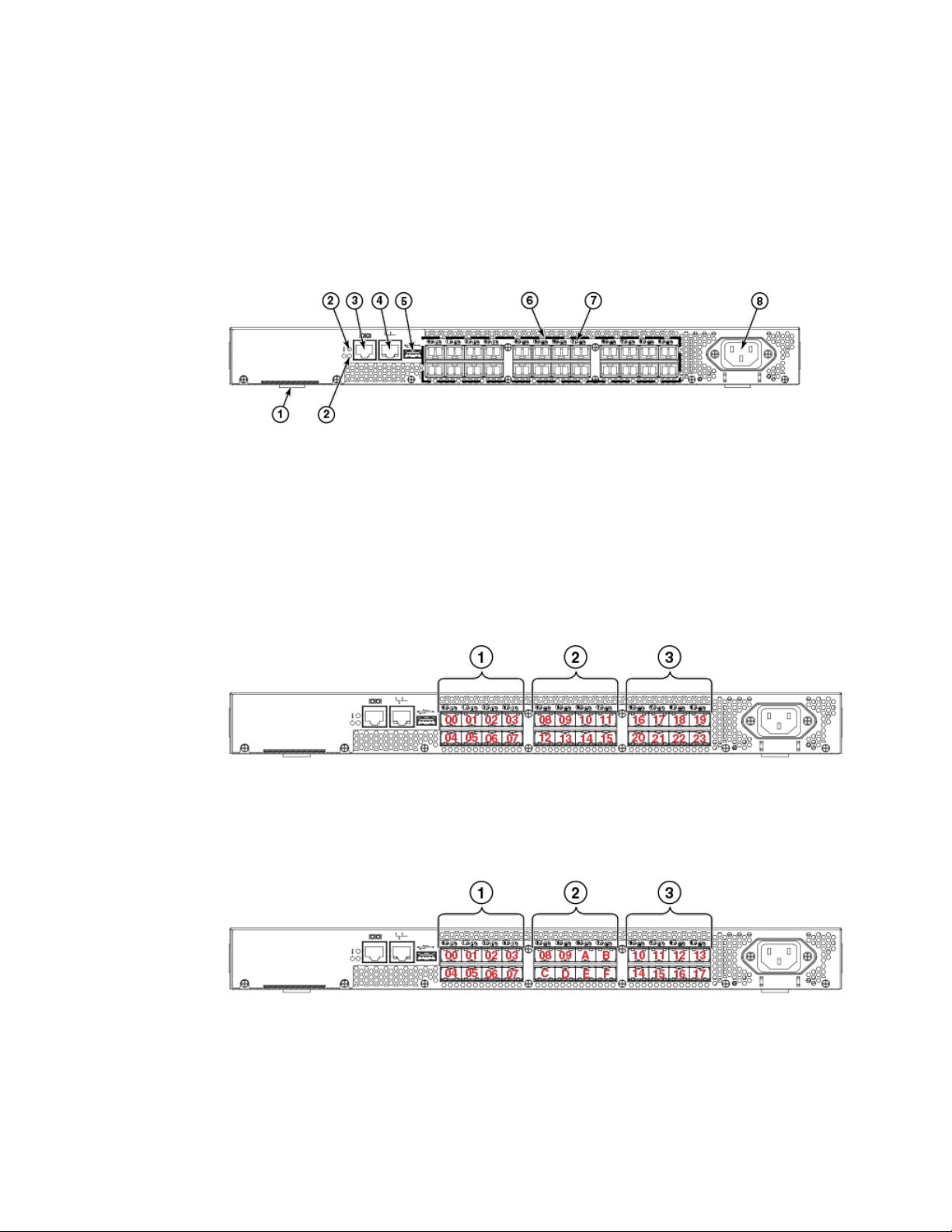
The port side of the Brocade 300 includes the system status LED, console port, Ethernet port and
LEDs, USB port, and Fibre Channel ports and the corresponding port status LEDs.
FIGURE 1 Port Side of the Brocade 300
1. Switch ID pull-out tab
2. System status (top) and power (bottom) LEDs
3. System RS232 console port (RJ-45)
4. Ethernet port with two Ethernet status LEDs
5. USB port
6. Fibre Channel port status LEDs
7. Fibre Channel ports (24)
8. AC power receptacle
FIGURE 2 Trunking port groups and decimal PIDs of the Brocade 300
1. Trunking port group 1: FC ports 00-07
2. Trunking port group 2: FC ports 08-15
3. Trunking port group 3: FC ports 16-23
FIGURE 3 Trunking port groups and hexadecimal PIDs of the Brocade 300
1. Trunking port group 1: FC ports 00-07
2. Trunking port group 2: FC ports 08-0F
3. Trunking port group 3: FC ports 10-17
12 Brocade 300 Hardware Reference Manual
53-1000862-06

Non-port side of the Brocade 300
The non-port side of the Brocade 300 is used solely for air flow. There are two labels on the bottom of
the chassis. On the right side is the Brocade standard agency label. On the left side is the Brocade
standard OEM data label.
Supported fabric configurations
The Brocade 300 is supported as an edge device in fabrics of up to 239 switches.
Ports on Demand license
Brocade 300 can be purchased with 8, 16, or 24 licensed ports. As your needs increase, you can
activate unlicensed ports by purchasing and installing the Brocade Ports on Demand (POD) optional
licensed product. After it has been installed, the license appears in the licenseShow command output
as Ports on Demand license .
By default, ports 0 through 7 are enabled on the Brocade 300. To enable ports 8 through 16, install a
POD license key. To enable ports 16 through 24, install another POD license.
To install a POD license, you can either use the supplied license key or generate a license key.
Typically the switch is shipped with a paper pack that specifies the transaction key to use with the
Software License Keys link. Use this transaction key on the Brocade Web site at www.brocade.com /
licensekeys and follow the instructions to generate the key. You can also use this site to generate other
license keys for your switch.
After you have installed the license keys, you must enable the ports. You can do so without disrupting
switch operation by using the portEnable command on each port individually. Alternatively, you can
disable and re-enable the switch to activate all ports simultaneously.
For detailed information on enabling additional ports using the POD license, refer to the Fabric OS
Administrator’s Guide .
Non-port side of the Brocade 300
ISL trunking groups
The Brocade 300 supports Interswitch Link (ISL) Trunking as a licensed feature. When this feature is
enabled, you can create trunked groups of up to eight contiguous ports. This means that you can create
up to three trunked groups that contain eight ports each.
The Fibre Channel ports on the Brocade 300 are numbered from left to right and color-coded into
groups of eight to indicate which ports you can combine into trunked groups.
Brocade 300 Hardware Reference Manual 13
53-1000862-06

Brocade 300 Introduction
FIGURE 4 Trunking Groups
A. Trunk group 1: Ports 0 through 7
B. Trunk group 2: Ports 8 through 15
C. Trunk group 3: Ports 16 though 23
NOTE
Brocade ISL Trunking is optional software that allows you to create trunking groups of ISLs between
adjacent switches. For more information about trunking, refer to the Fabric OS Administrator’s Guide
14 Brocade 300 Hardware Reference Manual
53-1000862-06

Brocade 300 Installation and Configuration
● Items included with the Brocade 300.............................................................................. 15
● Installation and safety considerations............................................................................. 15
● Installing a standalone Brocade 300............................................................................... 18
● EIA rack installation for a Brocade 300........................................................................... 18
● Brocade 300 configuration.............................................................................................. 19
Items included with the Brocade 300
The following items are included with the standard shipment of the Brocade 300. When you open the
Brocade 300 packaging, verify that these items are included in the package and that no damage has
occurred during shipping:
• One Brocade 300 Fibre Channel switch
• An accessory kit containing:
‐ Serial cable with an RJ-45 connector
‐ 6 ft. Power Cord
‐ Rubber feet, required for setting up the switch as a standalone unit
‐ Brocade Family Documentation CD
‐ Brocade 300 QuickStart Guide
‐ EZSwitch Setup CD
‐ Access Gateway Quick Start Guide
Installation and safety considerations
You can install the Brocade 300 switch in the following ways:
1. As a standalone unit on a flat surface.
2. In an EIA rack using a fixed-rail rack mount kit. The optional fixed-rail rack mount kit can be ordered
from your switch retailer.
3. In an EIA rack sing an optional slide-rail rack mount kit. The optional slide-rail rack mount kit can be
ordered from your switch retailer.
Installation precautions
When using this product, observe all danger, caution, and attention notices in this manual. The notices
are accompanied by symbols that represent the severity of the safety condition.
NOTE
Refer to Cautions and Danger Notices on page 45 for translations of safety notices for this product.
Brocade 300 Hardware Reference Manual
53-1000862-06
15
General precautions
General precautions
DANGER
The procedures in this manual are for qualified service personnel.
CAUTION
Changes or modifications made to this device that are not expressly approved by the party
responsible for compliance could void the user's authority to operate the equipment.
Power precautions
To install and operate the switch successfully, ensure the following:
• The primary outlet is correctly wired, protected by a circuit breaker, and grounded in accordance
with local electrical codes.
• Connect the power cord only to a grounded outlet.
DANGER
Make sure that the power source circuits are properly grounded, then use the power cord
supplied with the device to connect it to the power source.
• The supply circuit, line fusing, and wire size are adequate, as specified by the electrical rating on
the switch nameplate.
• This product is designed for an IT power system with phase-to-phase voltage of 230V. After
operation of the protective device, the equipment is still under voltage if it is connected to an IT
power system.
DANGER
To avoid high voltage shock, do not open the device while the power is on.
• The power supply standards provided in Power supply specifications on page 34 are met.
RTC battery precautions
Do not attempt to replace the real-time clock (RTC) battery. There is danger of explosion if the battery
is incorrectly replaced or disposed of. Contact your switch supplier if the real-time clock begins to lose
time.
DANGER
Risk of explosion if battery is replaced by an incorrect type. Dispose of used batteries
according to the instructions.
Environmental considerations
For successful installation and operation of the switch, ensure that the following environmental
requirements are met:
• At a minimum, adequate cooling requires that you install the switch with the non-port side, which
contains the air intake vents, facing the cool-air aisle.
• All equipment in the rack should force air in the same direction to avoid intake of exhaust air.
16 Brocade 300 Hardware Reference Manual
53-1000862-06
 Loading...