

Page 1
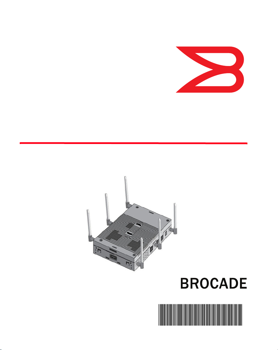
Brocade Mobility 1240
Access Point
Installation Guide
®
53-1002917-01
Page 2

Copyright © 2013 Brocade Communications Systems, Inc. All Rights Reserved.
ADX, AnyIO, Brocade, Brocade Assurance, the B-wing symbol, DCX, Fabric OS, ICX, MLX, MyBrocade, OpenScript, VCS,
VDX, and Vyatta are registered trademarks, and HyperEdge, The Effortless Network, and The On-Demand Data Center
are trademarks of Brocade Communications Systems, Inc., in the United States and/or in other countries. Other
brands, products, or service names mentioned may be trademarks of their respective owners.
Notice: This document is for informational purposes only and does not set forth any warranty, expressed or implied,
concerning any equipment, equipment feature, or service offered or to be offered by Brocade. Brocade reserves the
right to make changes to this document at any time, without notice, and assumes no responsibility for its use. This
informational document describes features that may not be currently available. Contact a Brocade sales office for
information on feature and product availability. Export of technical data contained in this document may require an
export license from the United States government.
The authors and Brocade Communications Systems, Inc. shall have no liability or responsibility to any person or entity
with respect to any loss, cost, liability, or damages arising from the information contained in this book or the computer
programs that accompany it.
The product described by this document may contain “open source” software covered by the GNU General Public
License or other open source license agreements. To find out which open source software is included in Brocade
products, view the licensing terms applicable to the open source software, and obtain a copy of the programming
source code, please visit http://www.brocade.com/support/oscd.
Brocade Communications Systems, Incorporated
Corporate and Latin American Headquarters
Brocade Communications Systems, Inc.
130 Holger Way
San Jose, CA 95134
Tel: 1-408-333-8000
Fax: 1-408-333-8101
E-mail: info@brocade.com
European Headquarters
Brocade Communications Switzerland Sàrl
Centre Swissair
Tour B - 4ème étage
29, Route de l'Aéroport
Case Postale 105
CH-1215 Genève 15
Switzerland
Tel: +41 22 799 5640
Fax: +41 22 799 5641
E-mail: emea-info@brocade.com
Asia-Pacific Headquarters
Brocade Communications Systems China HK, Ltd.
No. 1 Guanghua Road
Chao Yang District
Units 2718 and 2818
Beijing 100020, China
Tel: +8610 6588 8888
Fax: +8610 6588 9999
E-mail: china-info@brocade.com
Asia-Pacific Headquarters
Brocade Communications Systems Co., Ltd. (Shenzhen
WFOE)
Citic Plaza
No. 233 Tian He Road North
Unit 1308 – 13th Floor
Guangzhou, China
Tel: +8620 3891 2000
Fax: +8620 3891 2111
E-mail: china-info@brocade.com
Document History
Title Publication number Summary of changes Date
Brocade Mobility 1240 Access Point
Installation Guide
53-1002917-01 New Document May 2013
Page 3

Contents
Chapter 1 Introduction
Chapter 2 Hardware Installation
Warnings . . . . . . . . . . . . . . . . . . . . . . . . . . . . . . . . . . . . . . . . . . 1
Document conventions . . . . . . . . . . . . . . . . . . . . . . . . . . . . . . 2
Site preparation . . . . . . . . . . . . . . . . . . . . . . . . . . . . . . . . . . . . 2
Mobility 1240 Access Point package contents . . . . . . . . . . . 3
Features. . . . . . . . . . . . . . . . . . . . . . . . . . . . . . . . . . . . . . . 4
Installation instructions . . . . . . . . . . . . . . . . . . . . . . . . . . . . . . 7
Precautions. . . . . . . . . . . . . . . . . . . . . . . . . . . . . . . . . . . . . . . . 8
Access Point placement. . . . . . . . . . . . . . . . . . . . . . . . . . . . . . 8
Power over Ethernet . . . . . . . . . . . . . . . . . . . . . . . . . . . . . . . . . 9
Wall mount instructions. . . . . . . . . . . . . . . . . . . . . . . . . . . . . . 11
Wall mount procedure - new installation . . . . . . . . . . . . . 12
Wall Mount Procedure - Existing Access Point
Replacement . . . . . . . . . . . . . . . . . . . . . . . . . . . . . . . . . . . 13
Suspended ceiling T-Bar mount instructions . . . . . . . . . . . . . 14
Suspended Ceiling Tile (Plenum) Mount Instructions . . . . . . 16
Mobility 1240 Access Point antenna options. . . . . . . . . . . . . 20
LED Indicators . . . . . . . . . . . . . . . . . . . . . . . . . . . . . . . . . . . . . 23
Chapter 3 Initial Access Point Configuration
Initial configuration . . . . . . . . . . . . . . . . . . . . . . . . . . . . . . . . . 25
Brocade Mobility 1240 Access Point Installation Guide iii
53-1002917-01
Page 4

Chapter 4 Specifications
Electrical characteristics . . . . . . . . . . . . . . . . . . . . . . . . . . . . . 47
Physical characteristics . . . . . . . . . . . . . . . . . . . . . . . . . . . . . . 47
Radio characteristics . . . . . . . . . . . . . . . . . . . . . . . . . . . . . . . . 48
Chapter 5 Regulatory Information
Wireless Device Country Approvals . . . . . . . . . . . . . . . . . . . . . 49
Country Selection . . . . . . . . . . . . . . . . . . . . . . . . . . . . . . . 50
Health and Safety Recommendations . . . . . . . . . . . . . . . . . . 51
Warnings for Use of Wireless Devices . . . . . . . . . . . . . . . 51
Potetially Hazerdous Atmospheres - Fixed
Installations . . . . . . . . . . . . . . . . . . . . . . . . . . . . . . . . . . . . 51
RF Exposure Guidelines. . . . . . . . . . . . . . . . . . . . . . . . . . . . . . 52
EU . . . . . . . . . . . . . . . . . . . . . . . . . . . . . . . . . . . . . . . . . . . . 52
US and Canada . . . . . . . . . . . . . . . . . . . . . . . . . . . . . . . . . 52
Power Supply. . . . . . . . . . . . . . . . . . . . . . . . . . . . . . . . . . . 53
Radio Frequency Interference Requirements—FCC . . . . . . . . 53
Radio Transmitters (Part 15) . . . . . . . . . . . . . . . . . . . . . . 54
Radio Frequency Interference
Requirements – Canada . . . . . . . . . . . . . . . . . . . . . . . . . 54
Radio Transmitters . . . . . . . . . . . . . . . . . . . . . . . . . . . . . . 54
CE Marking and European Economic Area (EEA). . . . . . . . . . 56
Statement of Compliance. . . . . . . . . . . . . . . . . . . . . . . . . 56
Other Countries . . . . . . . . . . . . . . . . . . . . . . . . . . . . . . . . . 57
Waste Electrical and Electronic Equipment (WEEE). . . . . . . . 59
Chapter 6 Mobility 1240 China ROHS Compliance
iv Brocade Mobility 1240 Access Point Installation Guide
53-1002917-01
Page 5

Chapter
Introduction
The Brocade Mobility™ 1240 Access Point is a premium, Enterprise class, Access
Point positioned at the top of Brocade’s Access Point product line. The Mobility
1240 Access Point is a plenum rated, 3x3:3 802.11n Access Point utilizing two
802.11a/b/g/n radios.
A Mobility 1240 Access Point’s unique onboard operating system software enables
the Access Point to function as either a Virtual Controller AP capable of adopting
and managing up to 24 additional Mobility 1240 Access Points, a Standalone
Access Point or a Dependent mode Access Point managed by its connected
controller.
If new to Brocade Access Point technology, refer to the Brocade Mobility Series
Access Point Product Reference Guide to familiarize yourself with Access Point
technology and the feature set supported by the onboard operating system. The
guide is available, at http://www.brocade.com/support/
This document is written for the qualified network device installer.
Warnings
1
.
•
Read all installation instructions and site survey reports, and verify correct
equipment installation before connecting the Mobility 1240 Access Point.
•
Remove jewelry and watches before installing this equipment.
•
Verify any device connected to this unit is properly wired and grounded.
•
Verify there is adequate ventilation around the device, and that ambient
temperatures meet equipment operation specifications.
Brocade Mobility 1240 Access Point Installation Guide 1
53-1002917-01
Page 6

Document conventions
1
Document conventions
The following graphical alerts are used in this document to indicate notable
situations
NOTE
Tips, hints, or special requirements that you should take note of.
CAUTION
Care is required. Disregarding a caution can result in data loss or
equipment malfunction.
DANGER
Indicates a condition or procedure that could result in personal injury
or equipment damage.
Site preparation
•
Consult your site survey and network analysis reports to determine specific
equipment placement, power drops, and so on.
•
Assign installation responsibility to the appropriate personnel.
•
Identify and document where all installed components are located.
•
Ensure adequate, dust-free ventilation to all installed equipment.
•
Identify and prepare Ethernet and console port connections.
•
Verify cable lengths are within the maximum allowable distances for optimal
signal transmission.
2 Brocade Mobility 1240 Access Point Installation Guide
53-1002917-01
Page 7
Mobility 1240 Access Point package contents
Mobility 1240 Access Point package contents
A Mobility 1240 Access Point is available in external antenna models only. A
Mobility 1240 Access Point ships with the following:
•
Brocade Mobility 1240
•
Brocade Mobility 1240 Access Point Installation Guide (This Guide)
•
Wall mount screw and anchor kit
•
Accessories bag (LED light pipe for above the ceiling installations)
NOTE
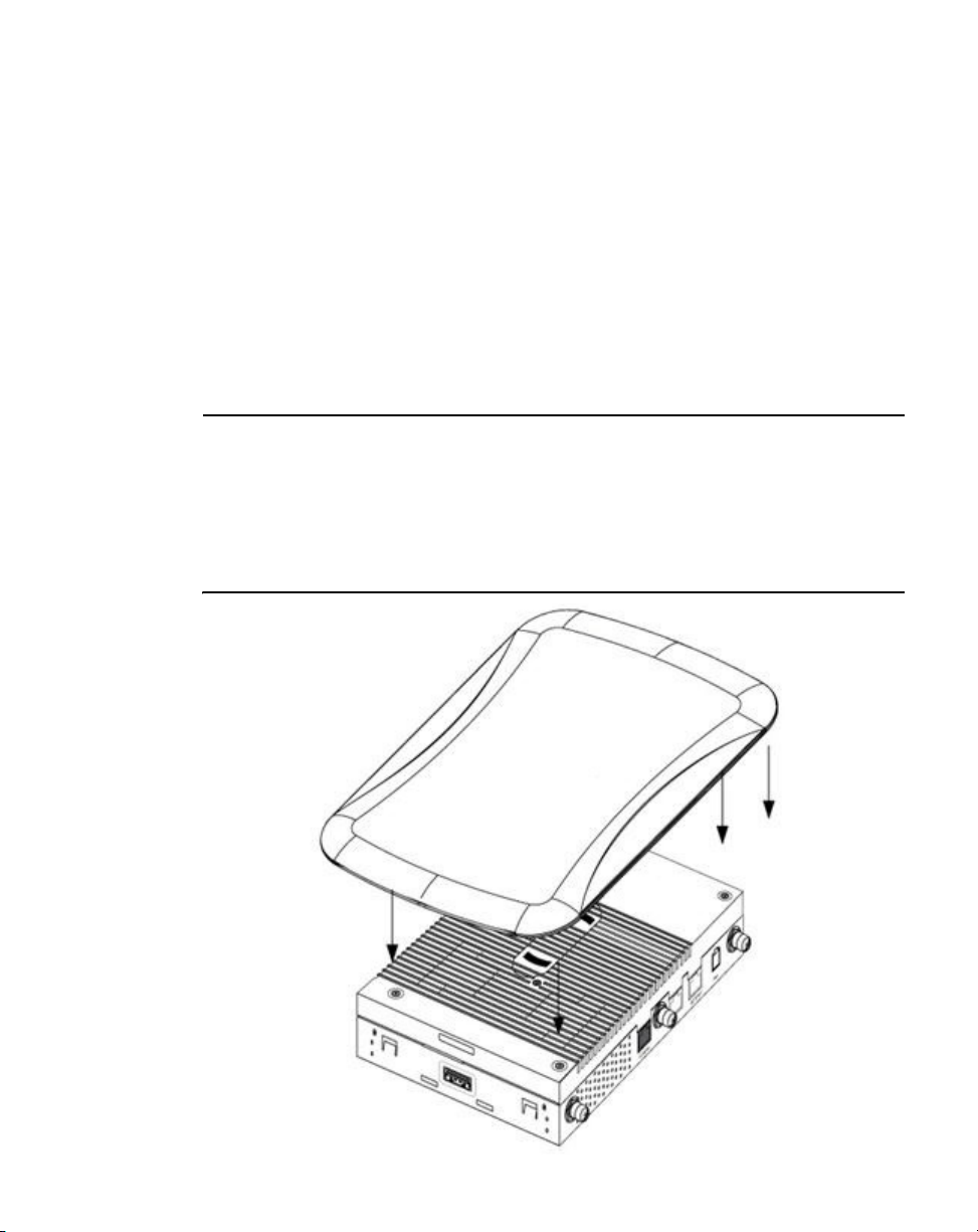
A Mobility 1240 Access Point can ship with a separately ordered protective cover
(facade) containing a 6-element MIMO antenna (Part No. ML-2452-PTA6M6-2).
When attached, LEDs continue to illuminate through the cover (similar to the
following illustration). A version of the facade is also available without the MIMO
antenna. This cover (Part No. 21-8132FAC-02) functions strictly as a protective cover
for the Access Point and provides no operational functionality.
1
Brocade Mobility 1240 Access Point Installation Guide 3
53-1002917-01
Page 8

Mobility 1240 Access Point package contents
1
Features
A Brocade Mobility 1240 minimally supports the following feature set:
•
3 RJ-45 connectors (GE1/POE, GE2 and Console)
•
LED indicators
•
Slots for wall mounting
•
Lock port for Kensington® style security lock
•
Two custom dual band radios
•
Features for snap-on module support through the Access Point’s USB interface
•
3x3 MIMO, 3 spatial streams
The Brocade Mobility 1240 has two RJ-45 connectors supporting 10/100/1000
Ethernet. GE1/POE accepts 802.3at or 802.3af compliant power from an external
source
.
NOTE
When operating in a Gigabit Ethernet environment, CAT-5e or CAT-6 cable is
recommended for Gigabit operation.
Contacting Brocade
When contacting Brocade support, please provide the following information:
•
Serial number of the unit
•
Model number or product name
•
Software version
Customer Support Web Site
Brocade Support Central Web site, located at www.brocade.com/support provides
information and online assistance including developer tools, software downloads,
product manuals and online repair requests.
4 Brocade Mobility 1240 Access Point Installation Guide
53-1002917-01
Page 9

Mobility 1240 Access Point package contents
Downloads
http://www.brocade.com/support/
Manuals
http://www.brocade.com/ethernetproducts
Because quality is our first concern at Brocade, we have made every effort to
ensure the accuracy and completeness of this document. However, if you find an
error or an omission, or you think that a topic needs further development, we want
to hear from you. Forward your feedback to: documentation@brocade.com
Provide the title and version number and as much detail as possible about your
comment, including the topic heading and page number and your suggestions for
improvement.
.
E-mail and telephone access
Go to http://www.brocade.com/services-support/index.page for email and
telephone contact information.
1
Warranty coverage
Contact Brocade Communications Systems using any of the methods listed above
for information about the standard and extended warranties.
Brocade Mobility 1240 Access Point Installation Guide 5
53-1002917-01
Page 10

Mobility 1240 Access Point package contents
1
6 Brocade Mobility 1240 Access Point Installation Guide
53-1002917-01
Page 11

Chapter
Hardware Installation
Installation instructions
A Mobility 1240 Access Point mounts either on a wall (with M4 x 25 pan head
screws and wall anchor - or equivalent) or on a suspended ceiling T-bar.
Once the Mobility 1240 Access Point is installed with facade and cabled, the cables
(Ethernet and module connections) should not be visible when looking directly at
the unit (ceiling and wall mounts).
To prepare for the installation:
1. Match the model number on the purchase order with the model numbers in the
packing list and on the case of the Access Point.
2. Verify the contents of the box include the intended Mobility 1240 Access Point,
and the included hardware matches the package contents on page 4.
Part Number Description
BR-AP124066040US 802.11n 3x3:3 access point dual radio US version
BR-AP124066040EU 802.11n 3x3:3 access point dual radio European version
BR-AP124066040WW 802.11n 3x3:3 access point dual radio non-US and non-EU (rest of
world) version
2
3. Review site survey and network analysis reports to determine the location and
mounting position for the Mobility 1240 Access Point.
4. Connect a CAT-5 or better Ethernet cable to a compatible 802.3at or 802.3af
power source and run the cable to the installation site. Ensure there is
sufficient slack on the cable to perform the installation steps.
NOTE
When operating in a Gigabit Ethernet environment, CAT-5e or CAT-6 cable is
recommended for Gigabit operation.
Brocade Mobility 1240 Access Point Installation Guide 7
53-1002917-01
Page 12

Precautions
2
Precautions
Before installing a Mobility 1240 Access Point, verify the following:
•
Your using the correctly rated power solution for the Mobility 1240 Access Point
(either 802.3af or 802.3at power over Ethernet or the PWRS-14000-247R
external power supply).
•
Brocade recommends you do not to install the Mobility 1240 Access Point in
wet or dusty areas.
•
Verify the environment has a continuous temperature range between 0° C to
50° C.
Access Point placement
For optimal performance, install the access point away from transformers,
heavy-duty motors, fluorescent lights, microwave ovens, refrigerators and other
industrial equipment. Signal loss can occur when metal, concrete, walls or floors
block transmission. Install the access point in an open area or add Access Points as
needed to improve coverage.
Antenna coverage is analogous to lighting. Users might find an area lit from far
away to be not bright enough. An area lit sharply might minimize coverage and
create dark areas. Uniform antenna placement in an area (like even placement of a
light bulb) provides even, efficient coverage.
Place the access point using the following guidelines:
•
Install the access point at an ideal height of 10 feet from the ground.
•
Orient the access point antennas vertically for best reception (applies to
external antenna models only).
To maximize the Access Point’s radio coverage area, Brocade recommends
conducting a site survey to define and document radio interference obstacles
before installing the Access Point.
8 Brocade Mobility 1240 Access Point Installation Guide
53-1002917-01
Page 13

Power over Ethernet
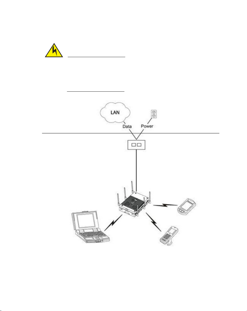
Power over Ethernet
A Mobility 1240 Access Point can receive power over Ethernet via an Ethernet cable
connected to the GE1/POE (LAN) port.
When users purchase a WLAN solution, they often need to place access points in
obscure locations. In the past, a dedicated power source was required for each
access point in addition to the Ethernet infrastructure. This often required an
electrical contractor to install power drops at each access point location. Power
over Ethernet merges power and Ethernet into one cable, reducing the burden of
installation and allowing optimal Access Point placement in respect to the intended
coverage area.
CAUTION
Using non-compliant power over Ethernet, or power over Ethernet
supporting legacy modes will not allow the Mobility 1240 to function at
optimum performance levels.
2
CAUTION
Do not plug 802.3af or 802.3at power over Ethernet into the access
point’s Console port. Connecting 802.3af or 802.3at power over
Ethernet into the console port can damage the port and void the
Mobility 1240’s product warranty.
The Brocade access point Power Supply (Part No. PWRS-14000-247R) is not
included with the access point and is orderable separately as an accessory. If the
access point is provided both POE power and PWRS-14000-247R power
concurrently, the access point will source power from the PWRS-14000-247R
supply only. Disconnecting AC power from the PWRS-14000-247R, causes the
access point to re-boot before sourcing power from power over Ethernet. If the AP is
operating using power over Ethernet, the AP will not automatically reboot if an AC
adapter is connected. The access point continues to operate with power supplied
from the AC adapter without change to the access point operating configuration. If
using AC adapter supplied power and a change to the AP’s operating configuration
is warranted, the access point needs to be manually rebooted by the customer.
Brocade Mobility 1240 Access Point Installation Guide 9
53-1002917-01
Page 14
Power over Ethernet
2
CAUTION
The access point supports any standards-based compliant power
source (including non-Brocade power sources). However, using the
wrong solution (including a POE system used on a legacy access point)
could either limit functionality or severely damage the access point and
void the product warranty.
wireless LAN
802.3af or 802.3at
power over Ethernet
To Mobility 1240
GE1/PoE port
10 Brocade Mobility 1240 Access Point Installation Guide
53-1002917-01
Page 15

Wall mount instructions
CAUTION
To avoid problematic performance and restarts, disable POE from a
wired switch port connected to an access point if mid-span power
sourcing equipment (PSE) is used between the two, regardless of the
manufacturer of the switch.
Ensure the cable length from the Ethernet source (host) to the power over Ethernet
and access point does not exceed 100 meters (333 ft).
Wall mount instructions
A wall mount deployment requires hanging the Mobility 1240 Access Point along its
width or length using two of three slots on the bottom of the unit. The Mobility 1240
can be mounted on to any plaster, wood or cement wall surface using the provided
wall anchors.
The hardware required to install the Mobility 1240 Access Point on a wall consists
of:
2
•
Two wide-shoulder Phillips pan head self-tapping screws (M3.5 x 0.6 x 23 mm)
•
Two wall anchors
•
Security cable (optional)
Optional customer provided installation tools include:
•
Security cable
•
Philips head screw driver, or drill and drill bit
Brocade Mobility 1240 Access Point Installation Guide 11
53-1002917-01
Page 16

Wall mount instructions
2
Wall mount procedure - new installation
This section describes a new Mobility 1240 Access Point installation with no
previous access point existing on the intended wall surface.
1. Place the access point against the wall, ensuring the access point’s logo is in
the correct orientation.
2. Mark the screw hole locations 152mm (6 in.) apart on the access point’s long
axis or 40mm (1.57 in.) apart on the access point’s short axis, depending on
the intended deployment orientation of the unit.
3. At each point, drill a hole in the wall and insert the anchor.
NOTE
When pre-drilling a hole the recommended hole size is 4mm (0.16in.).
4. Place the access point on the anchor. Insert screws through into the anchor.
5. If required, install and attach a Kensington security cable (customer supplied)
to the unit’s lock port.
6. Cable the access point using either power over Ethernet or the approved
Mobility 1240 power supply (PWRS-14000-247R).
For power over Ethernet installations:
a. Connect a RJ-45 CAT5e (or CAT6) Ethernet cable between the power over
Ethernet switch port and the access point’s GE1/POE port.
b. Ensure the cable length from the Ethernet source (host) to the power over
Ethernet and access point does not exceed 100 meters (333 ft).
For standard power adapter (non power over Ethernet) and line cord
installations:
a. Connect a RJ-45 Ethernet cable between the network data supply (host)
and the access point’s GE1/POE or GE2 port.
b. Verify the power adapter is correctly rated according to the country of
operation.
c. Connect the power supply line cord to the power adapter.
d. Attach the power adapter cable into the power connector on the access
point.
12 Brocade Mobility 1240 Access Point Installation Guide
53-1002917-01
Page 17

Wall mount instructions
e. Attach the power supply line cord to a power supply.
7. Attach supported 2.4 GHz or 5 GHz antennas to the connectors. For more
information on supported Mobility 1240 Access Point antennas, see “Mobility
1240 Access Point antenna options” on page 20.
8. Verify the access point is receiving power by observing the LEDs are lit or
flashing. For more information on Mobility 1240 Access Point LED behavior, see
“LED Indicators” on page 23.
9. The access point is ready to configure.
CAUTION
If not using power over Ethernet, ensure only the Mobility 1240 Access
Point designated power supply (PWRS-14000-247R) is used to supply
power to the access point. Using an incorrectly rated power supply
could damage the access point and void the product warranty. Do not
actually connect to the power source until the cabling portion of the
installation is complete.
2
Wall Mount Procedure - Existing Access Point Replacement
An existing Mobility 7131 or Mobility 7131N access point, installed on a wall
(plenum installation), can be replaced by a Mobility 1240 Access Point. Simply
remove the existing Mobility 7131 or Mobility 7131N from its mounting screws,
leave the mounting hardware in place and install the new Mobility 1240 Access
Point directly on to the existing mounting hardware. The cabling procedure for such
a replacement is as described in the previous section.
Brocade Mobility 1240 Access Point Installation Guide 13
53-1002917-01
Page 18

Suspended ceiling T-Bar mount instructions
2
Suspended ceiling T-Bar mount instructions
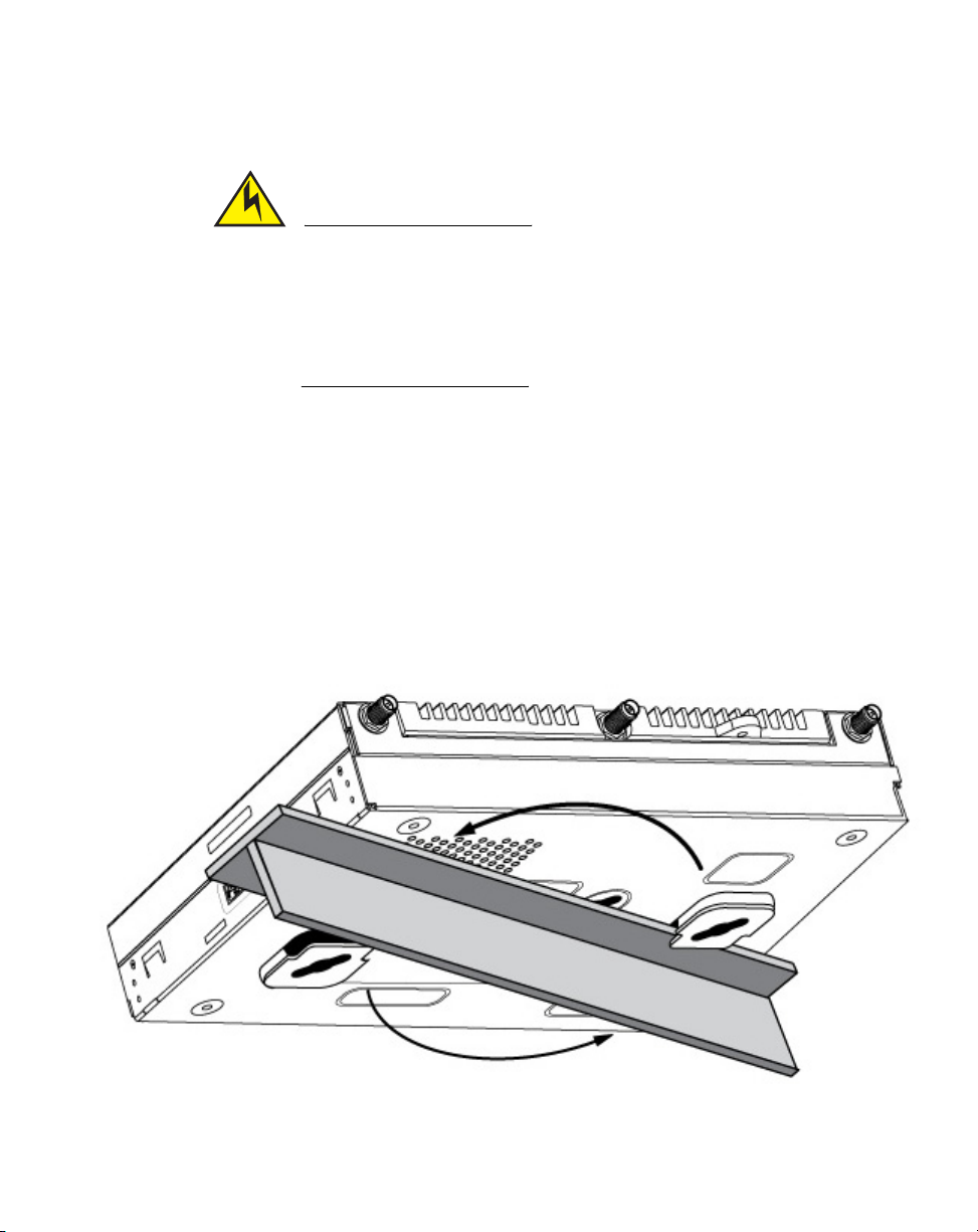
Ceiling mount requires holding the Mobility 1240 Access Point up against a T-bar of
a suspended ceiling grid and twisting the unit on to the T-bar. If deploying the
Mobility 1240 Access Point on a sculpted ceiling T-Bar, the access point mounting
kit (Part No. KT-135628-01) can optionally be used as well.
1. If required, install and attach a Kensington security cable (customer provided)
to the unit’s lock port.
2. Using only the mounting bracket from the mounting kit, rotate and click the
mounting bracket into the mounting slots on the Mobility 1240 Access Point.
3. Attach the antennas to their correct connectors. For more information on
supported Mobility 1240 Access Point antennas, see “Mobility 1240 Access
Point antenna options” on page 20.
4. Cable the access point using either power over Ethernet or the approved
Mobility 1240 Access Point power supply (PWRS-14000-247R).
For power over Ethernet installations:
a. Connect a RJ-45 CAT5e (or CAT6) Ethernet cable between the power over
Ethernet switch port and the access point’s GE1/POE port.
b. Ensure the cable length from the Ethernet source (host) to the power over
Ethernet and access point does not exceed 100 meters (333 ft).
For standard power adapter (non power over Ethernet) and line cord
installations:
a. Connect a RJ-45 Ethernet cable between the network data supply (host)
and the access point’s GE1/POE or GE2 port.
b. Verify the power adapter is correctly rated according to the country of
operation.
c. Connect the power supply line cord to the power adapter.
d. Attach the power adapter cable into the power connector on the access
point.
e. Attach the power supply line cord to a power supply.
14 Brocade Mobility 1240 Access Point Installation Guide
53-1002917-01
Page 19
Suspended ceiling T-Bar mount instructions
CAUTION
If not using power over Ethernet ensure only the Mobility 1240 Access
Point’s designated power supply (PWRS-14000-247R) is used to supply
power to the access point. Using an incorrectly rated power supply
could damage the access point and void the product warranty. Do not
actually connect to the power source until the cabling portion of the
installation is complete.
5. Verify the unit has power by observing the LEDs. For more information on
Mobility 1240 Access Point LED behavior, see “LED Indicators” on page 23.
6. Align the bottom of the ceiling T-bar with the back of the access point.
7. Orient the access point chassis by its length and the length of the ceiling T-bar.
8. Rotate the access point chassis 45 degrees clockwise.
9. Push the back of the access point chassis on to the bottom of the ceiling T-bar.
10. Rotate the access point chassis 45 degrees counter-clockwise. The clips click
as they fasten to the T-bar.
2
11. The access point is ready to configure.
Brocade Mobility 1240 Access Point Installation Guide 15
53-1002917-01
Page 20

Suspended Ceiling Tile (Plenum) Mount Instructions
2
Suspended Ceiling Tile (Plenum) Mount Instructions
An above the ceiling installation requires placing the access point above a
suspended ceiling and installing the provided light pipe under the ceiling tile for
viewing the rear panel status LEDs of the unit. An above the ceiling installation
enables installations compliant with drop ceilings, suspended ceilings and industry
standard tiles from .625 to .75 inches thick.
The mounting hardware required to install the access point above a ceiling consists
of:
•
Light pipe
•
Badge for light pipe
•
Safety wire (strongly recommended)
•
Security cable (optional)
NOTE
Notes or warnings about suspended ceiling mounts apply to all installations where
the unit is placed on suspended ceiling tile.
CAUTION
Brocade does not recommend mounting the access point directly to
any suspended ceiling tile with a thickness less than 12.7mm (0.5in.)
or a suspended ceiling tile with an unsupported span greater than
660mm (26in.). Brocade strongly recommends fitting the access point
with a safety wire suitable for supporting the weight of the device. The
safety wire should be a standard ceiling suspension cable or equivalent
steel wire between 1.59mm (.062in.) and 2.5mm (.10in.) in diameter.
NOTE
Remove the access point’s facade and antennas before installing in an above the
ceiling orientation. The access point is not certified for an above the ceiling
installation with its accessories installed.
16 Brocade Mobility 1240 Access Point Installation Guide
53-1002917-01
Page 21

Suspended Ceiling Tile (Plenum) Mount Instructions
To install the access point above a ceiling:
1. If possible, remove the ceiling tile from its frame and place it, finish side down,
on a work surface.
2. If required, install a safety wire, between 1.5mm (.06in.) and 2.5mm (.10in.) in
diameter, in the ceiling space.
3. If required, install and attach a security cable to the access point’s lock port.
4. Mark a point on the finished side of the tile where the light pipe is to be
located.
5. Create a light pipe path hole in the target position on the ceiling tile.
6. Use a drill to make a hole in the tile the approximate size of the access point
LED light pipe.
CAUTION
Brocade recommends care be taken not to damage the finished
surface of the ceiling tile when creating the light pipe hole and
installing the light pipe.
2
7. Remove the light pipe’s two rubber stoppers (from the access point) before
installing the light pipe.
8. Connect the light pipe to the bottom of the access point. The dual channel light
pipe is mated to the access point by firmly pressing the light pipe into the two
round openings that contained the two rubber plugs removed in the previous
step.
Brocade Mobility 1240 Access Point Installation Guide 17
53-1002917-01
Page 22

Suspended Ceiling Tile (Plenum) Mount Instructions
2
9. Fit the light pipe into hole in the tile from its unfinished side.
10. Slide the badge onto the light pipe from the finished side of the ceiling tile.
11. Attach the antennas to their correct connectors. For more information on
supported Mobility 1240 antennas, see “Mobility 1240 Access Point antenna
options” on page 20.
NOTE
Brocade recommends attaching safety wire to the access point safety wire tie
point or security cable (if used) to the access point’s lock port.
12. Align the ceiling tile into its former ceiling space.
13. Cable the access point using either power over Ethernet or the approved
Mobility 1240 power supply (PWRS-14000-247R).
For power over Ethernet installations:
18 Brocade Mobility 1240 Access Point Installation Guide
53-1002917-01
Page 23

Suspended Ceiling Tile (Plenum) Mount Instructions
a. Connect a RJ-45 CAT5e (or CAT6) Ethernet cable between the power over
Ethernet switch port and the access point’s GE1/POE port.
b. Ensure the cable length from the Ethernet source (host) to the power over
Ethernet and access point does not exceed 100 meters (333 ft).
For standard power adapter (non power over Ethernet) and line cord
installations:
a. Connect a RJ-45 Ethernet cable between the network data supply (host)
and the access point’s GE1/POE or GE2 port.
b. Verify the power adapter is correctly rated according to the country of
operation.
c. Connect the power supply line cord to the power adapter.
d. Attach the power adapter cable into the power connector on the access
point.
e. Attach the power supply line cord to a power supply.
CAUTION
If not using power over Ethernet, ensure only the Mobility 1240 Access
Point’s designated power supply (PWRS-14000-247R) is used to supply
power to the access point. Using an incorrectly rated power supply
could damage the access point and void the product warranty. Do not
actually connect to the power source until the cabling portion of the
installation is complete.
2
14. Verify the behavior of the access point LED light pipe. For more information on
Mobility 1240 Access Point LED behavior, see “LED Indicators” on page 23.
15. Place the ceiling tile back in its frame and verify it is secure.
16. The access point is ready to configure.
Brocade Mobility 1240 Access Point Installation Guide 19
53-1002917-01
Page 24

Mobility 1240 Access Point antenna options
2
Mobility 1240 Access Point antenna options
Brocade supports two antenna suites for a Mobility 1240 Access Point. One
antenna suite supporting the 2.4 GHz band and another antenna suite supporting
the 5 GHz band. Select an antenna model best suited to the intended operational
environment of the Mobility 1240 Access Point.
NOTE
In compliance with respective local regulatory law, Brocade AP software provides
professional installers the option to configure the antenna type and antenna gain for
approved antennas.
20 Brocade Mobility 1240 Access Point Installation Guide
53-1002917-01
Page 25

Mobility 1240 Access Point antenna options
The Mobility 1240’s supported 2.4 GHz antenna suite includes the following
models:
Part Number Antenna Type
ML-2499-5PNL-72-N Panel Antenna
ML-2499-APA2-01 Dipole Antenna
ML-2499-BPNA3-01R Panel Antenna
ML-2499-BYGA2-01R Yagi Antenna
ML-2499-FHPA9-01R Dipole Antenna
ML-2499-HPA3-01R Dipole Antenna
ML-2499-SD3-01R Patch Antenna
ML-2452-APA2-01 Dipole Antenna
ML-2452-PNA5-01R Panel Antenna
ML-2452-PNA7-01R Panel Antenna
ML-2452-HPA5-036 Dipole Antenna
ML-2452-APAG2A1-01 Dipole Antenna
2
The Mobility 1240’s supported 5 GHz antenna suite includes the following models:
Part Number Antenna Type
ML-5299-APA1-01R Dipole Antenna
ML-5299-FHPA10-01R Dipole Antenna
ML-5299-HPA1-01R Dipole Antenna
ML-5299-PTA1-01R Patch Antenna
ML-5299-WPNA1-01R Panel Antenna
ML-5299-BYGA15-012 Yagi Antenna
ML-2452-APA2-01 Dipole Antenna
ML-2452-PNA5-01R Panel Antenna
ML-2452-PNA7-01R Panel Antenna
ML-2452-HPA5-036 Dipole Antenna
ML-2452-APAG2A1-01 Dipole Antenna
Brocade Mobility 1240 Access Point Installation Guide 21
53-1002917-01
Page 26

Mobility 1240 Access Point antenna options
2
NOTE
ML-2499-BPNA3-01R and ML-2499-BYGA2-01R are not approved in EU countries.
The access point also supports a plastic facade (cover), separately ordered, that
either contains an antenna (Part No. ML-2452-PTA6M6-2) or serves as a plastic
cover without an antenna (Part No. 21-8132FAC-02).
For up-to-date information on supported antennas and antenna specifications,
refer to the Enterprise Wireless LAN Antenna Specification Guide. The guide is
available at http://www.brocade.com/support/
.
22 Brocade Mobility 1240 Access Point Installation Guide
53-1002917-01
Page 27

LED Indicators
LED Indicators
Both Integrated Antenna and External Antenna models have LED activity indicators
on the front of the case. With the External Antenna models mounted above a
ceiling, LEDs are at the center of an oval badge on the ceiling.
2
Brocade Mobility 1240 Access Point Installation Guide 23
53-1002917-01
Page 28

2
LED Indicators
The LEDs provide a status display indicating error conditions, transmission, and
network activity for the 5 GHz 802.11a/n (amber) radio and the 2.4 GHz
802.11b/g/n (green) radio.
Task 5 GHz Activity LED (Amber) 2.4 GHz Activity LED (Green)
Unconfigured
Radio
Normal
Operation
Firmware
Update
Locate AP
Mode
On On
•
If this radio band is enabled:
Blink at 5 second interval
•
If this radio band is disabled:
Off
•
If there is activity on this band:
Blink interval at 1 time per second
On Off
LEDs blink in an alternating green, red
and amber pattern using an irregular
blink rate. This LED state in no way
resembles normal operating
conditions.
•
•
•
LEDs blink in an alternating green,
red and amber pattern using an
irregular blink rate. This LED state in
no way resembles normal operating
conditions
If this radio band is enabled:
Blink at 5 second interval
If this radio band is disabled:
Off
If there is activity on this band:
Blink interval at 1 time per
second
The LEDs on the bottom of the access point are optionally viewed using a single
(customer installed) extended light pipe, adjusted as required to suit above the
ceiling installations. The light pipe uses a dual LED to display the same functionality
as the LEDs on the top of the access point.
24 Brocade Mobility 1240 Access Point Installation Guide
53-1002917-01
Page 29

Chapter
Initial Access Point Configuration
Initial configuration
Once the Access Point is installed and powered on, complete the following steps to
get the device up and running by using the Initial Setup Wizard:
1. Attach an Ethernet cable from the Access Point to a controller with an 802.3af
compatible power source or use the PWRS-14000-247R power supply to supply
power to the Mobility 1240 access point (once fully cabled).
If your host system is a DHCP server, an IP address is automatically assigned to
the Mobility 1240 Access Point and can be used for device connection.
However, if a DHCP server is not available, you will need to derive the IP
address from the Mobility 1240 Access Point MAC address. Using this method,
the last two bytes of the Mobility 1240 Access Point MAC address become the
last two octets of the IP address.
For Example:
MAC address - 00:C0:23:00:F0:0A
IP address equivalent - 169.254.240.10
To derive the Mobility 1240 Access Point’s IP address using its factory assigned
MAC address:
3
a. Open the Windows calculator be selecting Start > All Programs >
Accessories > Calculator. This menu path may vary depending on your
version of Windows.
b. With the Calculator displayed, select View > Scientific. Select the Hex radio
button.
c. Enter a hex byte of the Mobility 1240 Access Point’s MAC address. For
example, F0.
d. Select the Dec radio button. The calculator converts F0 into 240. Repeat
this process for the last Mobility 1240 Access Point MAC address octet.
Brocade Mobility 1240 Access Point Installation Guide 25
53-1002917-01
Page 30

Initial configuration
3
2. Point the Web browser to the Mobility 1240 access point’s IP address (using
3. Enter the default username admin in the Username field.
4. Enter the default password admin123 in the Password field.
https://). The following login screen displays.
5. Click the Login button to load the management interface.
NOTE
When logging in for the first time, you are prompted to change the password to
enhance device security in subsequent logins.
NOTE
If you get disconnected while running the wizard, you can connect again with the
Access Point’s actual IP address (once obtained) and resume the wizard.
6. Select the Start Wizard button to run the initial setup wizard.
26 Brocade Mobility 1240 Access Point Installation Guide
53-1002917-01
Page 31

Initial configuration
The setup wizard displays the first time the Mobility 1240 Access Point user
interface is accessed in order to define the Mobility 1240 Access Point’s initial
configuration.
3
7. If this is the first time the management interface has been accessed, a
dialogue displays to start the wizard. Select Start Wizard to run the wizard
Brocade Mobility 1240 Access Point Installation Guide 27
53-1002917-01
Page 32

Initial configuration
3
The first page of the Initial AP Setup Wizard displays the Navigation Panel and
Introduction for the configuration activities comprising the Access Point's initial
setup.
A green checkmark to the left of an item in the Navigation Panel defines the
listed task as having its minimum required configuration parameters set
correctly. A red X defines the task as still requiring at least one parameter be
defined correctly.
28 Brocade Mobility 1240 Access Point Installation Guide
53-1002917-01
Page 33

Initial configuration
The Introduction screen displays a list of the basic configuration activities
supported by the Initial Setup Wizard.
3
8. Select Save/Commit within each page to save the updates made to that page's
configuration. Select Next to proceed to the next page listed in the Navigation
Panel. Select Back to revert to the previous screen in the Navigation Panel
without saving your updates.
NOTE
While you can navigate to any page in the navigation panel, you cannot
complete the Initial AP Setup Wizard until each task in the Navigation Panel has
a green checkmark.
Brocade Mobility 1240 Access Point Installation Guide 29
53-1002917-01
Page 34

Initial configuration
3
9. Select Next. The Initial AP Setup Wizard displays the Access Point Type screen
to define the Access Point's Standalone versus Virtual Controller AP
functionality and the way the Access Point is adopted to a controller.
10. Select an Access Point Type from the following options:
30 Brocade Mobility 1240 Access Point Installation Guide
53-1002917-01
Page 35

Initial configuration
•
Virtual Controller AP - When more than one Access Point is deployed, a
single Access Point can function as a Virtual Controller AP. Up to 24 Access
Points can be connected to, and managed by, a single Virtual Controller AP
of the same Mobility 1240 Access Point model.
•
Standalone AP -Select this option to deploy this Access Point as an
autonomous fat Access Point. A Standalone AP isn't managed by a Virtual
Controller AP, or adopted by a controller.
NOTE
If you are designating the Access Point as a Standalone AP, Brocade
recommends that the Access Point’s UI, and not the CLI, be used exclusively to
define its device configuration. The CLI provides the ability to define more than
one profile and the UI does not. Consequently, the two interfaces cannot be
used collectively to manage profiles without an administrator encountering
problems.
11. Adopted to Controller - Select this option when deploying the Access Point as a
controller managed (Dependent mode) Access Point. Selecting this option
closes the Initial AP Setup Wizard. An adopted Access Point obtains its
configuration from a profile stored on its managing controller. Any manual
configuration changes are overwritten by the controller upon reboot.
3
Select the Automatic controller discovery option to enable the Access Point to
be discovered and adopted using layer 2 settings. If you prefer layer 3 adoption,
select the Static Controller Configuration option, and define the addresses of
the preferred controllers.
Brocade Mobility 1240 Access Point Installation Guide 31
53-1002917-01
Page 36

Initial configuration
3
If you are using the static method, you will also need to define whether the
Access Point receives an IP address using DHCP or if IP resources are provided
statically.
32 Brocade Mobility 1240 Access Point Installation Guide
53-1002917-01
Page 37

Initial configuration
12. Select Next. The Initial AP Setup Wizard displays the Access Point Mode screen
to define the Access Point's routing or bridging mode functionality.
3
Brocade Mobility 1240 Access Point Installation Guide 33
53-1002917-01
Page 38

Initial configuration
3
13. Select a Access Point Mode from the available options.
•
Router Mode - In Router Mode, the Access Point routes traffic between the
local network (LAN) and the Internet or external network (WAN). Router
mode is recommended in a deployment supported by just a single Access
Point.
•
Bridge Mode - In Bridge Mode, the AP depends on an external router for
routing LAN and WAN traffic. Routing is generally used on one device,
whereas bridging is typically used in a larger network. Thus, select Bridge
Mode when deploying this Access Point with numerous peer APs
supporting clients on both the 2.4 and 5GHz radio bands.
34 Brocade Mobility 1240 Access Point Installation Guide
53-1002917-01
Page 39

Initial configuration
14. Select Next. The Initial AP Setup Wizard displays the LAN Configuration screen
to set the Access Point's LAN interface configuration.
3
Brocade Mobility 1240 Access Point Installation Guide 35
53-1002917-01
Page 40

Initial configuration
3
15. Set the following DHCP and Static IP Address/Subnet information for the LAN
interface:
•
Use DHCP - Select the checkbox to enable an automatic network address
configuration using the Access Point’s DHCP server.
•
Static IP Address/Subnet - Enter an IP Address and a subnet for the Access
Point's LAN interface. If Use DHCP is selected, this field is not available.
When selecting this option, define the following DHCP Server and Domain
Name Server (DNS) resources, as those fields will become enabled on the
bottom portion of the screen.
•
Use on-board DHCP server to assign IP addresses to wireless clients
-Select the checkbox to enable the Access Point’s DHCP server to
provide IP and DNS information to clients on the LAN interface.
•
Range - Enter a starting and ending IP Address range for client
assignments on the LAN interface. Avoid assigning IP addresses from
x.x.x.1 - x.x.x.10 and x.x.x.255, as they are often reserved for standard
network services. This is a required parameter.
•
Default Gateway - Define a default gateway address for use with the
default gateway. This is a required parameter.
•
DNS Forwarding - Select this option to allow a DNS server to translate
domain names into IP addresses. If this option is not selected, a primary
and secondary DNS resource must be specified. DNS forwarding is useful
when a request for a domain name is made but the DNS server,
responsible for converting the name into its corresponding IP address,
cannot locate the matching IP address.
•
Primary DNS - Enter an IP Address for the main Domain Name Server
providing DNS services for the Access Point's LAN interface.
•
Secondary DNS - Enter an IP Address for the backup Domain Name
Server providing DNS services for the Access Point's LAN interface.
36 Brocade Mobility 1240 Access Point Installation Guide
53-1002917-01
Page 41

Initial configuration
16. Select Next. The Initial AP Setup Wizard displays the WAN Configuration screen
to set the Access Point's WAN interface configuration.
3
Brocade Mobility 1240 Access Point Installation Guide 37
53-1002917-01
Page 42

Initial configuration
3
17. Set the following DHCP and Static IP Address/Subnet information for the WAN
18. Select Next. The Initial AP Setup Wizard displays the Radio Configuration
interface:
•
Use DHCP - Select the checkbox to enable an automatic network address
configuration using the Access Point’s DHCP server.
•
Static IP Address/Subnet - Enter an IP Address/Subnet and gateway for the
Access Point's WAN interface. These are required fields
•
The port connected to the WAN - Select the port used as the physical
Access Point connection to the external network. The ports available differ
depending on the Access Point model deployed. Access Point models with
a single port have this option fixed.
•
Enable NAT on the WAN Interface - Select the checkbox to allow traffic to
pass between the Access Point's WAN and LAN interfaces.
screen to define support for the 2.4GHz radio band, 5GHz radio band or to set
the radio's functionality as a dedicated sensor.
NOTE
The ADSP Sensor Server field displays at the bottom of the screen only if a
radio has been dedicated as a sensor.
38 Brocade Mobility 1240 Access Point Installation Guide
53-1002917-01
Page 43

Initial configuration
19. Set the following parameters for the radio:
•
Configure as a Data Radio - Select this option to dedicate this radio for
WLAN client support in either the selected 2.4 or 5 GHz radio band.
•
Radio Frequency Band - Select either the 2.4 GHz or 5.0 GHz radio
band to use with the radio when selected as a Data Radio. The
selected band is used for WLAN client support. Considers selecting
one radio for 2.4 GHz and another for 5 GHz support (if using a dual
radio model) when supporting clients in both the 802.11b/g and
802.11n bands.
•
Power Level - Use the spinner control to select a 1 - 23 dBm minimum
power level to assign to this radio in selected 2.4 or 5.0 GHz band. 1
dBm is the default setting.
•
Channel Mode - Select either Random, Best or Static. Select Random
for use with a 802.11a/n radio. To comply with Dynamic Frequency
Selection (DFS) requirements in the European Union, the 802.11a/n
radio uses a randomly selected channel each time the Access Point is
powered on.
Select Best to enable the Access Point to scan non-overlapping
channels and listen for beacons from other Access Points. After the
channels are scanned, it will select the channel with the fewest Access
Points. In the case of multiple Access Points on the same channel, it
will select the channel with the lowest average power level. When
Constantly Monitor is selected, the Access Point will continuously scan
the network for excessive noise and sources of interference. Select
Static to assign the Access Point a permanent channel and scan for
noise and interference only when initialized.
•
Configure as a Sensor Radio - Select this option to dedicate the radio to
sensor support exclusively. When functioning as a sensor, the radio scans
in sensor mode across all channels within the 2.4 and 5.0 GHz bands to
identify potential threats within the Access Point managed network. If you
are dedicating a radio as a sensor resource, you must specify a primary
and secondary ADSP server as an ADSP management resource.
•
Disable the Radio - Select this option to disable this radio, thus prohibiting
it from either providing WLAN or sensor support. Before rendering the radio
offline, verify this course of action with your network administrator.
3
Brocade Mobility 1240 Access Point Installation Guide 39
53-1002917-01
Page 44

Initial configuration
3
20. Select Next. The Initial AP Setup Wizard displays the Wireless LAN Setting
screen to define network address and security settings for two WLAN
configurations available to the Access Point as part of the Initial Setup Wizard.
Once the Access Point has an initial configuration defined, numerous
additional WLAN configurations can be set.
40 Brocade Mobility 1240 Access Point Installation Guide
53-1002917-01
Page 45

Initial configuration
21. Set the following parameters for each of the two WLAN configurations available
as part of this Initial AP Setup Wizard:
•
SSID - Enter or modify the Services Set Identification (SSID) associated
with the WLAN. The WLAN name is auto-generated using the SSID until
changed by the user. The maximum number of characters is 32. Do not
use < > | “ & \ ? , This is a required parameter for each WLAN.
•
WLAN Type - Set the data protection scheme used by clients and Access
Points within the WLAN. The following options are available:
•
No Authentication and no Encryption - Select this option to provide no
security between the Access Point and connected clients on this
WLAN.
•
Captive Portal Authentication and No Encryption - Select this option to
use a Web page (either internally or externally hosted) to authenticate
users before access is granted to the network. If using this option,
define whether a local or external RADIUS authentication resource is
used.
•
PSK Authentication and WPA2 Encryption - Select the option to
implement a pre-shared key that must be correctly shared between
the Access Point and requesting clients using this WLAN. If using this
option, specify a WPA key in either ASCII (8-63 characters) or HEX (64
characters) format.
•
EAP Authentication and WPA2 Encryption - Select this option to
authenticate clients within this WLAN through the exchange and
verification of certificates. If you are using this option, define whether
a local or external RADIUS authentication resource is used.
•
WPA Key - If a WPA key is required (PSK Authentication and WPA2
Encryption), enter an alphanumeric string of 8 to 63 ASCII characters or 64
HEX characters as the primary string both transmitting and receiving
authenticators must share. The alphanumeric string allows character
spaces. This passphrase saves the administrator from entering the 256-bit
key each time keys are generated.
•
RADIUS Server - If the WLAN requires a RADIUS server to validate user
credentials, designate whether the Access Point is using an External
RADIUS Server resource or the Access Point's own Onboard RADIUS
Server. If you are using an external RADIUS server resource, provide the IP
address of the external server and the shared secret used to authenticate
the request.
3
Brocade Mobility 1240 Access Point Installation Guide 41
53-1002917-01
Page 46

Initial configuration
3
22. Select Next. The Initial AP Setup Wizard displays the RADIUS Server
NOTE
If you are using the Access Point’s onboard RADIUS server, an additional
RADIUS Server Configuration screen displays within the Navigation Panel on
the left-hand side of the screen. Use this screen to create user accounts
validated when the Access Point authenticates client connection requests to
the onboard RADIUS server.
Configuration screen if the Access Point’s onboard RADIUS server is required to
validate user requests. If an onboard RADIUS server is not required, the Initial
AP Setup Wizard displays the Country/Date/Time screen to set device
deployment, administrative contact and system time information.
42 Brocade Mobility 1240 Access Point Installation Guide
53-1002917-01
Page 47

Initial configuration
23. Refer to the Username, Password, Description, and Actions columns to review
credentials of existing RADIUS Server user accounts. Add new accounts or edit
the properties of existing accounts as updates are required.
24. Refer to the Add On-Board RADIUS Server Users field to set the following
parameters for a user account:
•
Username - If you are adding a new user account, create a username up to
X characters in length. The username cannot be revised if modifying the
user configuration. This is a required parameter.
•
Password - Provide (or modify) a password between X - X characters in
length entered each time a requesting client attempts access to the AP
managed network using the Access Point's onboard RADIUS server. This is
a required parameter.
•
Confirm Password - Re-enter (or modify) the password as a means of
confirming the password. This is a required parameter.
•
Description - Optionally provide a description of the user account as means
of further differentiating it from others.
25. When completed, select Add User to commit a new user, Modify User to commit
a modified user or Reset to clear the screen without updating the
configuration. Selecting Reset clears the field of all entered user account
information.
3
Brocade Mobility 1240 Access Point Installation Guide 43
53-1002917-01
Page 48

Initial configuration
3
26. Select Next. The Initial AP Setup Wizard displays the Country/Date/Time
screen to set device deployment, administrative contact and system time
information. The system time can either be set manually or be supplied by a
dedicated Network Time Protocol (NTP) resource.
44 Brocade Mobility 1240 Access Point Installation Guide
53-1002917-01
Page 49

Initial configuration
27. Refer to the Country and Time Zone field to set the following device deployment
information:
•
Location - Define the location of the Access Point. The Location parameter
acts as a reminder of where the AP is deployed within the Brocade
managed wireless network.
•
Contact - Specify the contact information for the administrator. The
credentials provided should accurately reflect the individual responding to
service queries.
•
Country - Select the Country where the Access Point is deployed. The
Access Point prompts for the correct country code on the first login. A
warning message also displays stating an incorrect country setting may
result in illegal radio operation. Selecting the correct country is central to
legal operation. Each country has its own regulatory restrictions
concerning electromagnetic emissions and the maximum RF signal
strength that can be transmitted. This is a required parameter.
•
Time Zone - Set the time zone where the Access Point is deployed. This is a
required parameter. The setting should be complimentary with the
selected deployment country.
28. If an NTP resource is unavailable, set the System Date and Time (calendar
date, time, and AM/PM designation).
3
29. Optionally enter the IP address of a server used to provide system time to the
Access Point. Once the IP address is entered, the Network Time Protocol (NTP)
functionality is engaged automatically for synchronization with the NTP
resource.
30. If an NTP resource is unavailable, set the System Date and Time (calendar
date, time, and AM/PM designation).
31. Optionally, enter the IP address of a server used to provide system time to the
Access Point. Once the IP address is entered, the Network Time Protocol (NTP)
functionality is automatically engaged for synchronization with the NTP
resource.
32. Select Next. The Initial AP Setup Wizard displays the Summary and Commit
screen to summarize the screens (pages) and settings updated using the Initial
AP Setup Wizard.
No user intervention or additional settings are required within this screen. It is
a means of validating the configuration before its deployed.
Brocade Mobility 1240 Access Point Installation Guide 45
53-1002917-01
Page 50

Initial configuration
3
If a screen shows settings not intended as part of the initial configuration, the
screen can be selected from within the Navigation Panel and its settings
modified accordingly.
33. If the configuration displays as intended, select the Save/Commit button to
implement these settings to the Access Point’s configuration. If additional
changes are warranted based on the summary, either select the target page
from the Navigational Panel, or use the Back and Next buttons to scroll to the
target screen.
46 Brocade Mobility 1240 Access Point Installation Guide
53-1002917-01
Page 51

Chapter
Specifications
Electrical characteristics
A Mobility 1240 has the following electrical characteristics:
Operating Current &
Voltage
Physical characteristics
A Mobility 1240 has the following physical characteristics:
Dimensions
Housing
Weight (without facade)
Operating Temperature
48VDC, 0.625A (AUX input voltage)
48VDC, 0.75A (PWRS-14000-247R power supply)
9 inches x 6.00 inches x 1.75 inches
22.9 cm x 15.2 cm x 4.4 cm
Metal
3.2 lbs / 1.45 kg
32°F to 122°F/0°C to 50°C
4
Storage Temperature
Operating Humidity
Storage Humidity
Operating Altitude
(max)
Storage Altitude
(max)
Electrostatic Discharge
Brocade Mobility 1240 Access Point Installation Guide 47
53-1002917-01
-40°F to 185°F/-40°C to 85°C
5 to 95% Relative Humidity non-condensing
85% Relative Humidity non-condensing
8,000 ft @ 28C
30,000 ft @ 12C
+/-15kV Air and +/-8kV Contact @ 50% Relative Humidity
Page 52

Radio characteristics
4
Radio characteristics
The
Mobility 1240
has the following radio characteristics:
Data Rates Supported
Wireless Medium
Network Standards
Transmit Power
Adjustment
802.11b: 1,2,5.5,11Mbps
802.11g: 1,2,5.5,11,6,9,12,18,24,36,48, and 54Mbps
802.11a: 6,9,12,18,24,36,48, and 54Mbps
802.11n: MCS 0-23 up to 450Mbps
Direct Sequence Spread Spectrum (DSSS),
Orthogonal Frequency Division Multiplexing (OFDM)
Spatial multiplexing (MIMO)
Tra nsmi t Bea mfo rmin g
802.11a, 802.11b, 802.11g, 802.3, 802.11n
1dB increments
48 Brocade Mobility 1240 Access Point Installation Guide
53-1002917-01
Page 53

Chapter
Regulatory Information
This device is approved under the Brocade Communications, Inc. brand.
This guide applies to the following Model Numbers: Mobility 1240.
All Brocade devices are designed to be compliant with rules and regulations in
locations they are sold and will be labeled as required.
Any changes or modifications to Brocade equipment, not expressly approved by
Brocade, could void the user's authority to operate the equipment.
When Brocade devices are professionally installed, the Radio Frequency Output
Power will not exceed the maximum allowable limit for the country of operation.
Antennas: Use only the supplied or an approved replacement antenna.
Unauthorized antennas, modifications, or attachments could cause damage and
may violate regulations.
This device is only to be used with a Brocade Wireless Controller.
Wireless Device Country Approvals
5
Regulatory markings, subject to certification, are applied to the device signifying
the radio(s) is/are approved for use in the following countries: United States,
Canada, Japan, China, S. Korea, Australia, and Europe 1
Please refer to the Declaration of Conformity (DoC) for details of other country
markings. This is available at http://www.motorolasolutions.com/doc
Note: For 2.4GHz or 5GHz Products: Europe includes, Austria, Belgium, Bulgaria,
Czech Republic, Cyprus, Denmark, Estonia, Finland, France, Germany, Greece,
Hungary, Iceland, Ireland, Italy, Latvia, Liechtenstein, Lithuania, Luxembourg,
Malta, Netherlands, Norway, Poland, Portugal, Romania, Slovak Republic, Slovenia,
Spain, Sweden, Switzerland and the United Kingdom.
Operation of the device without regulatory approval is illegal.
Brocade Mobility 1240 Access Point Installation Guide 49
53-1002917-01
.
Page 54

Wireless Device Country Approvals
5
Country Selection
Select only the country in which you are using the device. Any other selection will
make the operation of this device illegal. The US version of Access Point will only
have US listed in the country selection table. The US version will be sold /used in
the US protectorates: American Samoa, Guam, Puerto Rico, US Virgin Islands.
Frequency of Operation – FCC and IC
You are reminded of the need to observe restrictions on the use of radio devices in
fuel depots, chemical plants etc. and areas where the air contains chemicals or
particles (such as grain, dust, or metal powders).
2.4 GHz Only
The available channels for 802.11b/g operation in the US are Channels 1 to 11.
The range of channels is limited by firmware.
5 GHz Only
The use in the UNII (Unlicensed National Information Infrastructure) band 1
(5150-5250 MHz) is restricted to Indoor Use Only; any other use will make the
operation of this device illegal.
Industry Canada Statement:
Caution: The device for the band 5150-5250 MHz is only for indoor usage to reduce
potential for harmful interference to co-Channel mobile satellite systems. High
power radars are allocated as primary users (meaning they have priority) of
5250-5350 MHz and 5650-5850 MHz and these radars could cause interference
and/or damage to LE-LAN devices.
Avertissement: Le dispositif fonctionnant dans la bande 5150-5250 MHz est
réservé uniquement pour une utilisation à l'intérieur afin de réduire les risques de
brouillage préjudiciable aux systèmes de satellites mobiles utilisant les mêmes
canaux.
Les utilisateurs de radars de haute puissance sont désignés utilisateurs principaux
(c.-à-d., qu'ils ont la priorité) pour les bands 5250-5350 MHz et 5650-5850 MHz et
que ces radars pourraient causer du brouillage et/ou des dommages aux
dispositifs LAN-EL.
50 Brocade Mobility 1240 Access Point Installation Guide
53-1002917-01
Page 55

Health and Safety Recommendations
Health and Safety Recommendations
Warnings for Use of Wireless Devices
Please observe all warning notices with regard to the usage of wireless
devices.
Potetially Hazerdous Atmospheres - Fixed Installations
You are reminded of the need to observe restrictions on the use of radio devices in
fuel depots, chemical plants etc. and areas where the air contains chemicals or
particles (such as grain, dust, or metal powders)
Safety in Hospitals
Wireless devices transmit radio frequency energy and may affect medical
electrical equipment. When installed adjacent to other equipment, it is
advised to verify that the adjacent equipment is not adversely affected.
.
5
Pacemakers
Pacemaker manufacturers recommended that a minimum of 15cm (6 inches) be
maintained between a handheld wireless device and a pacemaker to avoid
potential interference with the pacemaker. These recommendations are consistent
with independent research and recommendations by Wireless Technology
Research.
Persons with Pacemakers:
•
Should ALWAYS keep the device more than 15cm (6 inches) from their
pacemaker when turned ON.
•
Should not carry the device in a breast pocket.
•
Should use the ear furthest from the pacemaker to minimize the potential for
interference.
•
If you have any reason to suspect that interference is taking place, turn OFF
your device.
Brocade Mobility 1240 Access Point Installation Guide 51
53-1002917-01
Page 56

RF Exposure Guidelines
5
Other Medical Devices
Please consult your physician or the manufacturer of the medical device, to
determine if the operation of your wireless product may interfere with the medical
device.
RF Exposure Guidelines
Safety Information
Reducing RF Exposure - Use Properly
Only operate the device in accordance with the instructions supplied.
International
The device complies with internationally recognized standards covering human
exposure to electromagnetic fields from radio devices. For information on
“International” human exposure to eletromagnic fields refer to the Please refer to
the Declaration of Conformity (DoC). This is available at
http://www.motorolasolutions.com/doc
.
EU
Remote and Standalone Antenna Configurations
To comply with EU RF exposure requirements, antennas that are mounted
externally at remote locations or operating near users at stand-alone desktop of
similar configurations must operate with a minimum separation distance of 1 meter
from all persons.
US and Canada
Co-located statement
To comply with FCC RF exposure compliance requirements, the antenna used for
this transmitter must not be co-located or operating in conjunction with any other
transmitter/antenna except those already approved in this filling.
52 Brocade Mobility 1240 Access Point Installation Guide
53-1002917-01
Page 57

Radio Frequency Interference Requirements—FCC
Remote and Standalone Antenna Configurations
To comply with FCC RF exposure requirements, Antennas that are mounted
externally must be professionally installed at a fixed location and operate with a
minimum distance of 30 cm from all persons.
IC Radiation Exposure Statement:
This equipment complies with IC RSS-102 radiation exposure limits set forth for an
uncon-trolled environment. This equipment should be installed and operated with
minimum distance 30cm between the radiator & your body.
Déclaration d'exposition aux radiations:
Cet équipement est conforme aux limites d'exposition aux rayonnements IC établies
pour un environnement non contrôlé. Cet équipement doit être installé et utilisé
avec un minimum de 30 cm de distance entre la source de rayonnement et votre
corps.
Power Supply
5
This device must be powered from a 802.3af or 802.3at compliant power source
which has been certified by the appropriate agencies, or by a LISTED Type no.
PWRS-14000-247R or AP-PSBIAS-2P3-ATR, direct plug-in power supply, marked
Class 2 or LPS (IEC60950-1, SELV). Use of alternative Power Supply will invalidate
any approvals given to this unit and may be dangerous.
Radio Frequency Interference Requirements—FCC
This equipment has been tested and found to comply with the limits for a
Class B digital device, pursuant to Part 15 of the FCC rules. These limits
are designed to provide reasonable protection against harmful
interference in a residential installation. This equipment generates, uses
and can radiate radio frequency energy and, if not installed and used in
accordance with the instructions, may cause harmful interference to radio communications.
However there is no guarantee that interference will not occur in a particular installation. If
this equipment does cause harmful interference to radio or television reception, which can
be determined by turning the equipment off and on, the user is encouraged to try to correct
the interference by one or more of the following measures:
Brocade Mobility 1240 Access Point Installation Guide 53
53-1002917-01
Page 58

Radio Frequency Interference Requirements—FCC
5
•
Reorient or relocate the receiving antenna
•
Increase the separation between the equipment and receiver
•
Connect the equipment into an outlet on a circuit different from that to which
the receiver is connected
•
Consult the dealer or an experienced radio/TV technician for help.
Radio Transmitters (Part 15)
This device complies with Part 15 of the FCC Rules. Operation is subject to the
following two conditions: (1) this device may not cause harmful interference, and
(2) this device must accept any interference received, including interference that
may cause undesired operation.
The use of 5 GHz WLAN's, for use in the US, have the following restrictions:
•
Notched Band 5.60 - 5.65 GHz
Radio Frequency Interference Requirements – Canada
This Class B digital apparatus complies with Canadian ICES-003. Cet appareil
numérique de la classe B est conforme à la norme NMB-003 du Canada.
Radio Transmitters
For RLAN Devices:
The use of 5 GHz RLAN’s, for use in Canada, have the following restrictions:
•
Restricted Band 5.60 – 5.65 GHz
This device complies with RSS 210 of Industry Canada. Operation is subject to the
following two conditions: (1) this device may not cause harmful interference and (2)
this device must accept any interference received, including interference that may
cause undesired operation.
Ce dispositif est conforme à la norme CNR-210 d'Industrie Canada applicable aux
appareils radio exempts de licence. Son fonctionnement est sujet aux deux
conditions suivantes: (1) le dispositif ne doit pas produire de brouillage
préjudiciable, et (2) ce dispositif doit accepter tout brouillage reçu, y compris un
brouillage susceptible de provoquer un fonctionnement indésirable.
54 Brocade Mobility 1240 Access Point Installation Guide
53-1002917-01
Page 59

Radio Frequency Interference Requirements—FCC
Label Marking: The Term "IC:" before the radio certification only signifies that
Industry Canada technical specifications were met
To reduce potential radio interference to other users, the antenna type and its gain
should be so chosen that the equivalent isotropically radiated power (EIRP) is not
more than that permitted for successful communication.
The device could automatically discontinue transmission in case of absence of
information to trans-mit, or operational failure. Note that this is not intended to
prohibit transmission of control or signaling information or the use of repetitive
codes where required by the technology.
The maximum antenna gain permitted for devices in the band 5725-5825 MHz
shall comply with the e.i.r.p. limits specified for point-to-point and non point-to-point
operation as appropriate.
In compliance with respective local regulatory law, Brocade AP software provides
professional installers the option to configure the antenna type and antenna gain
for approved antennas.
This radio transmitter (identify the device by certification number, or model number
if Category II) has been approved by Industry Canada to operate with the antenna
types listed below with the maximum permissible gain and required antenna
impedance for each antenna type indicated. Antenna types not included in this list,
having a gain greater than the maximum gain indicated for that type, are strictly
prohibited for use with this device.
5
Le présent émetteur radio (identifier le dispositif par son numéro de certification ou
son numéro de modèle s'il fait partie du matériel de catégorie I) a été approuvé par
Industrie Canada pour fonctionner avec les types d'antenne énumérés ci-dessous
et ayant un gain admissible maximal et l'impédance requise pour chaque type
d'antenne. Les types d'antenne non inclus dans cette liste, ou dont le gain est
supérieur au gain maximal indiqué, sont strictement interdits pour l'exploitation de
l'émetteur.
Refer to section 2.8 of this guide for a listing of the 2.4 and 5 GHz antennas initially
approved for use with the Mobility 1240.
Brocade Mobility 1240 Access Point Installation Guide 55
53-1002917-01
Page 60

CE Marking and European Economic Area (EEA)
5
CE Marking and European Economic Area (EEA)
The use of 2.4GHz RLAN’s, for use through the EEA, have the following restrictions:
•
Maximum radiated transmit power of 100 mW EIRP in the frequency range
2.400 -2.4835 GHz.
•
France outside usage, the equipment is restricted to 2.400-2.45 GHz
frequency range.
•
Italy requires a user license for outside usage.
Statement of Compliance
Brocade hereby, declares that this device is in compliance with the essential
requirements and other relevant provisions of Directive 1999/5/EC. A Declaration
of Conformity may be obtained from http://www.motorolasolutions.com/doc
Japan (VCCI) - Voluntary Control Council for Interference
Class B ITE
.
Korea Warning Statement for Class B
56 Brocade Mobility 1240 Access Point Installation Guide
53-1002917-01
Page 61

CE Marking and European Economic Area (EEA)
Other Countries
Australia
Use of 5GHz RLAN’s in Australia is restricted in the following band 5.50 – 5.65GHz.
Brazil
Declarações Regulamentares para Mobility 1240 - Brasil
Nota: A marca de certificação se aplica ao Transceptor, modelo Mobility 1240. Este
equipamento opera em caráter secundário, isto é, não tem direito a proteção
contra interferência prejudicial, mesmo de estações do mesmo tipo, e não pode
causar interferência a sistemas operando em caráter primário. Para maiores
informações sobre ANATEL consulte o site: www.anatel.gov.br
Chile
Este equipo cumple con la Resolución No 403 de 2008, de la Subsecretaria de
telecomunicaciones, relativa a radiaciones electromagnéticas.
5
China
Mexico
Restrict Frequency Range to: 2.450 – 2.4835 GHz.
Brocade Mobility 1240 Access Point Installation Guide 57
53-1002917-01
Page 62

CE Marking and European Economic Area (EEA)
5
S. Korea
Taiwan
在
5.25-5.35
秭赫頻帶內操作之無線資訊傳輸設備,限於室內使用
Thailand
Turkish WEEE Statement of Compliance
EEE Yönetmeliğine Uygundur
58 Brocade Mobility 1240 Access Point Installation Guide
53-1002917-01
Page 63

Waste Electrical and Electronic Equipment (WEEE)
Waste Electrical and Electronic Equipment (WEEE)
For information on WEEE, please go to:
http://www.brocade.com/company/corporate-responsibility/
corporate-citizenship/product-recycling/weee.page.
5
Brocade Mobility 1240 Access Point Installation Guide 59
53-1002917-01
Page 64

Waste Electrical and Electronic Equipment (WEEE)
5
60 Brocade Mobility 1240 Access Point Installation Guide
53-1002917-01
Page 65

Chapter
Mobility 1240 China ROHS Compliance
BR1240
有毒有害物质或元素
铅
汞
镉
部件名称
(Parts)
金属部件
(Metal Parts)
电路模块
(Circuit Modules)
电缆及电缆组件
(Cables and Cable Assemblies)
塑料和聚合物部件
(Plastic and Polymeric Parts)
光学和光学组件
(Optics and Optical Components)
电池
(Batteries)
(Pb)
XOO O O O
XOO O O O
XOO O O O
OOO O O O
OOO O O O
OOO O O O
(Hg)
(Cd)
六价铬
6+
(Cr
)
多溴联
(PBB)
苯
6
15
多溴二苯
醚
(PBDE)
O
:表示该有毒有害物质在该部件所有均质材料中的含量均在
SJ/T11363-2006
标准规定的限量要求以下。
X
:表示该有毒有害物质至少在该部件的某 一均质 材料中 的含量超出
SJ/T11363-2006
标准规定的限量要求。
对销售之日的所售产品,本表表示,公司供应链的电子信息产品可能包含这些
物质。注意:在所售产品中可能会也可能不会含有所有所列的部件。
This table was created to comply with China RoHS requirements for Brocade’s
Mobility 1240 Access Point.
Brocade Mobility 1240 Access Point Installation Guide 61
53-1002917-01
Page 66

Page 67

Page 68

 Loading...