

Broan HRV90H Series, HRV90HT, HRV90HS, ERV90HC Series, HRV90HCS Installation Instructions Manual
...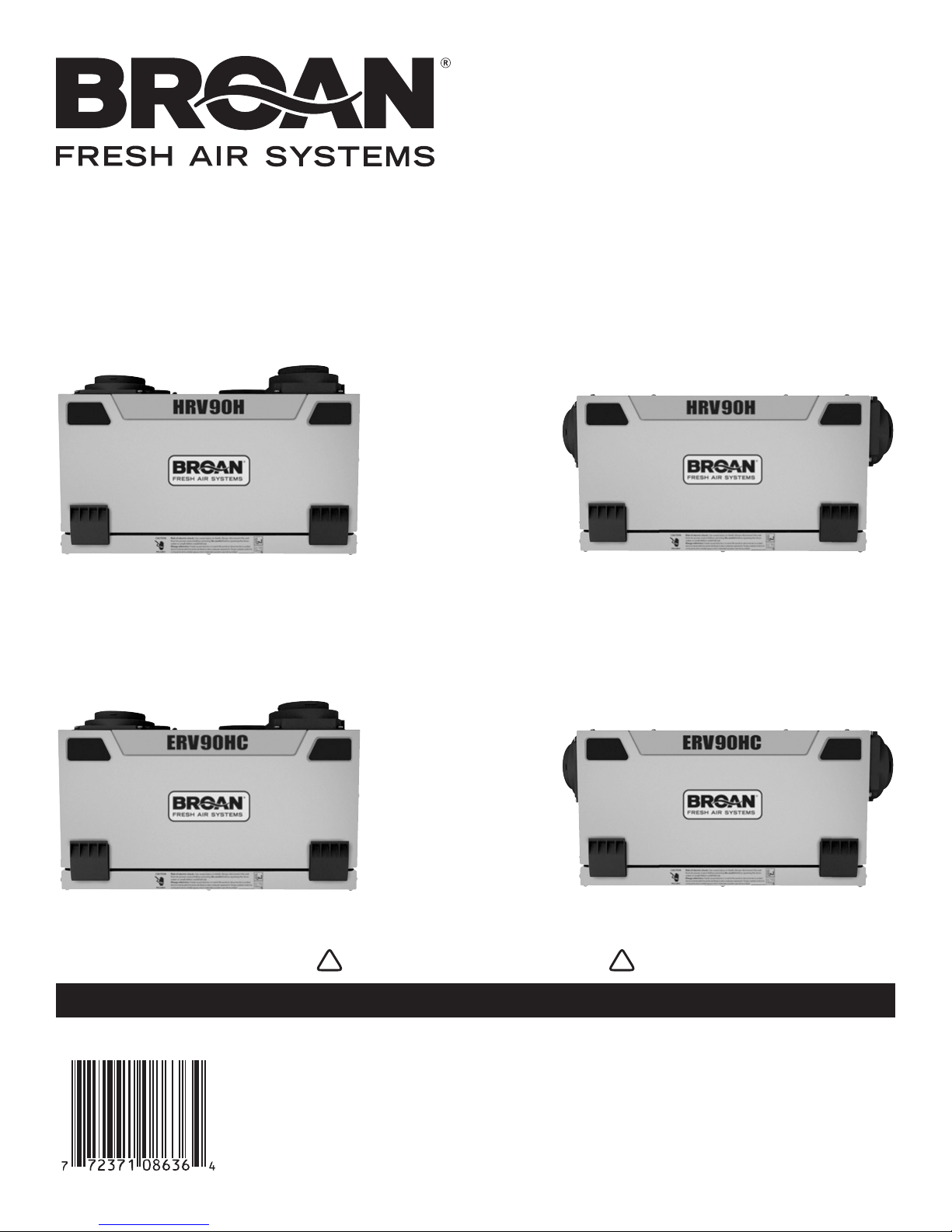
INSTALLATION INSTRUCTIONS
HRV90H AND ERV90HC
Model no.: HRV90HT
(HRV with top ports)
VB0082
Model no.: ERV90HCT
(ERV with top ports)
Model no.: HRV90HS
(HRV with side ports)
VB0081
Model no.: ERV90HCS
(ERV with side ports)
VB0080
READ AND SAVE THESE INSTRUCTIONS
VB0079
! !
RESIDENTIAL USE ONLY
06010C rev. 11

ABOUT THIS MANUAL
Because of the large amount of models covered by this publication, the illustrations are typical ones. Some details of your unit may be
slightly different than the ones shown.
Please take note that this manual uses the following symbols to emphasize particular information:
!
WARNING
Identifies an instruction which, if not followed, might cause serious personal injuries including possibility of death.
CAUTION
Identifies an instruction which, if not followed, may severely damage the unit and/or its components.
NOTE: Indicates supplementary information needed to fully complete an instruction.
We welcome any suggestions you may have concerning this manual and/or the unit, and we would appreciate hearing your comments on
ways to better serve you. Please contact us by phone at 1-800-558-1711.
ABOUT THESE UNITS
LIMITATION
For residential (domestic) installation only. Installation work and electrical wiring must be done by a qualified person(s) in accordance with
all applicable codes and standards, including fire-rated construction codes and standards.
i WARNING
TO REDUCE THE RISK OF FIRE, ELECTRIC SHOCK, OR INJURY TO PERSON(S) OBSERVE THE FOLLOWING:
1. Use this unit only in the manner intended by the manufacturer. If you have questions, contact the manufacturer at the address or
telephone number listed in the warranty.
2. Before servicing or cleaning the unit, disconnect power cord from electrical outlet.
3. This unit is not designed to provide combustion and/or dilution air for fuel-burning appliances.
4. When cutting or drilling into wall or ceiling, do not damage electrical wiring and other hidden utilities.
5. Do not use this unit with any solid-state speed control device other than main optional wall control VT4W, and no other optional
auxiliary wall controls than 60-minute crank timer and/or 20-minute lighted push button and/or Dehumidistat.
6. This unit must be grounded. The power supply cord has a 3-prong grounding plug for your personal safety. It must be plugged into a
mating 3-prong grounding receptacle, grounded in accordance with the national electrical code and local codes and ordinances. Do
not remove the ground prong. Do not use an extension cord.
7. Do not install in a cooking area or connect directly to any appliances.
8. Do not use to exhaust hazardous or explosive materials and vapors.
9. When performing installation, servicing or cleaning these units, it is recommended to wear safety glasses and gloves.
10. Due to the weight of the unit, two installers are recommended to perform installation.
11. When applicable local regulation comprise more restrictive installation and/or certification requirements, the aforementioned
requirements prevail on those of this document and the installer agrees to conform to these at his own expenses.
CAUTION
1. To avoid prematurate clogged filters, turn OFF the unit during construction or renovation.
2. Please read specification label on product for further information and requirements.
3. Be sure to duct air outside – Do not intake/exhaust air into spaces within walls or ceiling or into attics, crawl spaces, or garage.
4. Intended for residential installation only in accordance with the requirements of NFPA 90B.
5. Do not run any air ducts directly above or closer than 2 ft (0.61 m) to any furnace or its supply plenum, boiler, or other heat producing
appliance. If a duct has to be connected to the furnace return plenum, it must be connected not closer than 9’ 10” (3 m) from this plenum
connection to the furnace.
6. The ductwork is intended to be installed in compliance with all local and national codes that are applicable.
7. When leaving the house for a long period of time (more than two weeks), a responsible person should regularly check if the unit
operates adequately.
8. If the ductwork passes through an unconditioned space (e.g.: attic), the unit must operate continuously except when performing
maintenance and/or repair. Also, the ambient temperature of the house should never drop below 18°C (65°F).
2

TABLE OF CONTENTS
1. T ECHNICAL DATA ................................................................................................................................ 4-6
1.1 AIR DISTRIBUTION (NORMAL OPERATION) ..................................................................................................................4
1.2 A
1.3 S
1.4 P
1.5 D
1.6 C
2. TYPICAL INSTALLATIONS ........................................................................................................................7-8
2.1 FULLY DUCTED SYSTEM ..........................................................................................................................................7
2.2 C
2.3 S
2.4 I
3. INSTALLATION ................................................................................................................................... 9-15
3.1 INSPECT THE CONTENT OF THE BOX ..........................................................................................................................9
3.2 L
3.3 U
3.4 H
3.5 P
3.6 I
3.7 C
3.8 I
3.9 I
IR DISTRIBUTION (RECIRCULATION OR DEFROST MODE) .............................................................................................4
PECIFICATIONS .....................................................................................................................................................4
ERFORMANCE CHARTS ..........................................................................................................................................5
IMENSIONS .........................................................................................................................................................6
ONTROLS AND LINKAGE POSSIBILITY ........................................................................................................................6
ENTRAL DRAW POINT ...........................................................................................................................................7
IMPLIFIED INSTALLATION .........................................................................................................................................7
NSTALLATION FOR ERV UNITS ONLY ........................................................................................................................8
OCATING THE UNIT ...............................................................................................................................................9
NIT PREPARATION ................................................................................................................................................9
OW TO HANG THE UNIT ......................................................................................................................................10
LANNING OF THE DUCTWORK................................................................................................................................10
NSTALLING THE DUCTWORK AND REGISTERS ......................................................................................................10-12
ONNECTING THE DUCTS TO THE UNIT ....................................................................................................................13
NSTALLING THE TANDEM
NSTALLING 2 EXTERIOR HOODS ............................................................................................................................. 15
®
TRANSITION KIT ...........................................................................................................13-15
4. CONTROLS .................................................................................................................................... 16-18
4.1 INTEGRATED CONTROL ..........................................................................................................................................16
4.2 E
4.3 VT4W
4.4 O
LECTRICAL CONNECTION TO OPTIONAL WALL CONTROLS .....................................................................................16-17
OPTIONAL MAIN WALL CONTROL OPERATION .................................................................................................17
PTIONAL AUXILIARY WALL CONTROLS OPERATION ..................................................................................................18
5. ELECTRICAL CONNECTION TO THE FURNACE ..............................................................................................18
6. WIRING DIAGRAM .................................................................................................................................19
7. B ALANCING THE UNIT ............................................................................................................................ 20
8. CONNECTING THE DRAIN (HRV UNITS ONLY) .......................................................................................... 21
9. MAINTENANCE................................................................................................................................ 22-23
9.1 BIANNUAL MAINTENANCE ................................................................................................................................. 22-23
9.2 A
NNUAL MAINTENANCE .........................................................................................................................................23
10 . S ERVICE PARTS .................................................................................................................................. 24
11. TROUBLESHOOTING ......................................................................................................................... 25-26
3

1. TECHNICAL DATA
1.1 AIR DISTRIBUTION (NORMAL OPERATION)
HRV
ERV
EXHAUST AIR
FROM BUILDING
FRESH AIR
TO BUILDING
VF0038
FRESH AIR
FROM OUTSIDE
EXHAUST AIR
TO OUTSIDE
1.2 AIR DISTRIBUTION (RECIRCULATION OR DEFROST MODE)
HRV
EXHAUST AIR
FROM BUILDING
FILTERED AIR
TO BUILDING
VF0036
Outdoors Temperature HRV Defrost Cycles
Celcius (°C) Fahrenheit (°F) Defrosting (minutes)
-5 to -27
-27 and less
23 to -17
-17 and less
EXHAUST AIR
FROM BUILDING
FRESH AIR
TO BUILDING
EXHAUST AIR
FROM BUILDING
FILTERED AIR
TO BUILDING
8
10
FRESH AIR
FROM OUTSIDE
EXHAUST AIR
TO OUTSIDE
VF0039
ERV
VF0037
Operation time (minutes)
between each defrost cycle
25
22
Celcius (°C) Fahrenheit (°F) Defrosting (minutes)
-5 to -27
-27 and less
1.3 SPECIFICATIONS
Outdoors Temperature ERV Defrost Cycles
Operation time (minutes)
between each defrost cycle
23 to -17
-17 and less
9
10
MODEL HRV ERV
WEIGHT 42 LB. (19 KG) 45 LB. (20.4 KG)
VAL PORTS FIT 5” (127 MM) DUCTS FIT 5” (127 MM) DUCTS
O
DRAIN DIAMETER 1/2” (12 MM) N/A
NSTALLATION CHAINS, SPRINGS AND HOOKS (PROVIDED WITH THE UNIT)
I
OTOR SPEEDS HIGH AND LOW SPEEDS
M
ELECTRICAL SUPPLY 120 V, 60 HZ 120 V, 60 HZ
POWER CONSUMPTION 100 WATTS 104 WATTS
4
28
22
1. TECHNICAL DATA (CONT’D)
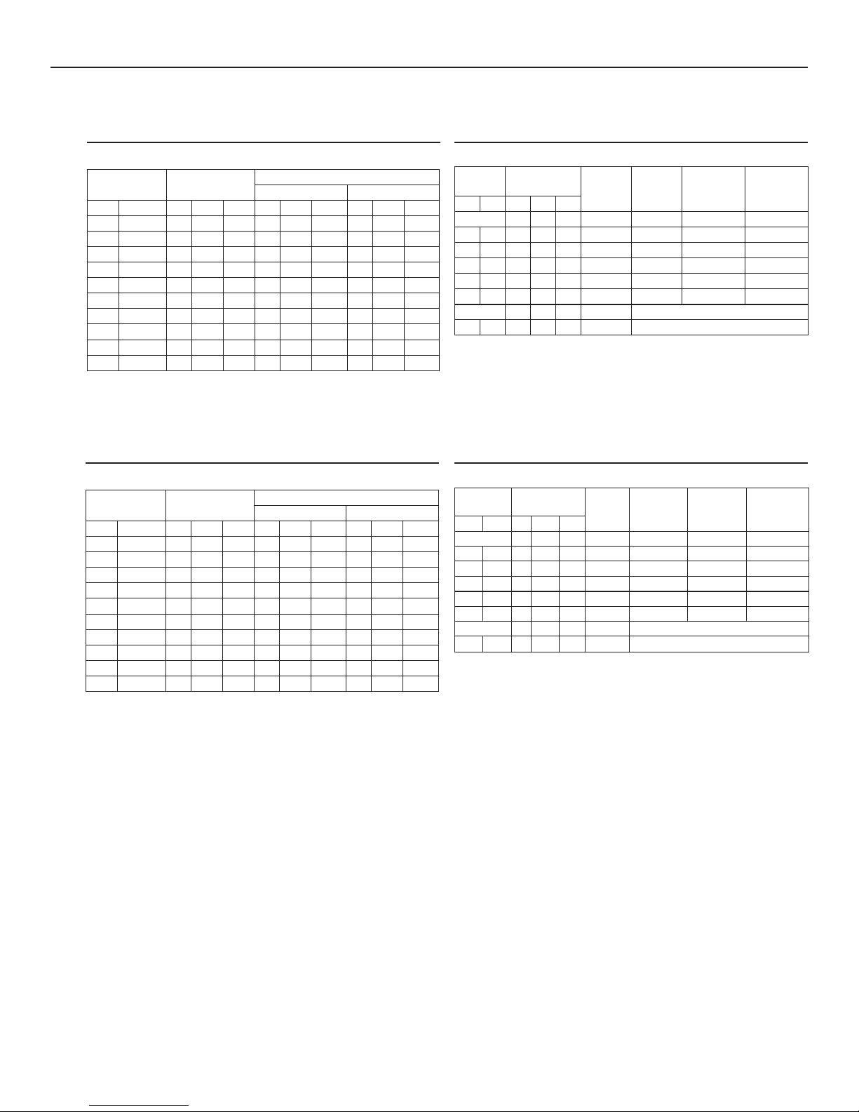
1.4 PERFORMANCE CHARTS
1.4.1 HRV UNITS
VENTILATION PERFORMANCE
EXTERNAL
STATIC PRESSURE
PAIN. W.G. L/SCFMM3/HL/SCFM M3/HL/SCFM M3/H
25 0.1 53 111 191 53 112 190 57 120 204
50 0.2 51 107 184 51 108 184 54 114 194
75 0.3 48 101 172 48 102 173 52 110 187
100 0.4 46 98 167 47 99 168 49 105 178
125 0.5 43 91 155 43 92 156 47 100 170
150 0.6 41 88 148 42 88 151 45 96 163
175 0.7 39 82 139 39 83 141 43 91 155
200 0.8 37 79 134 38 80 136 40 85 144
225 0.9 34 73 124 35 74 126 37 79 134
250 1.0 34 71 121 34 72 122 36 76 129
NET SUPPLY
AIR FLOW
NOTE: All speci cations are subject to change without notice.
1.4.2 ERV UNITS
GROSS AIR FLOW
SUPPLY EXHAUST
VENTILATION PERFORMANCE
EXTERNAL
STATIC PRESSURE
PAIN. W.G. L/SCFMM3/HL/SCFM M3/HL/SCFM M3/H
25 0.1 54 115 195 55 117 199 55 117 199
50 0.2 53 112 190 54 115 195 54 114 193
75 0.3 51 109 185 53 111 189 52 110 187
100 0.4 49 105 178 50 106 180 50 106 180
125 0.5 48 102 173 49 104 177 49 103 175
150 0.6 45 96 163 47 99 168 47 99 168
175 0.7 44 93 158 45 94 160 45 94 160
200 0.8 42 89 151 43 92 156 42 88 150
225 0.9 40 85 144 41 87 148 41 87 148
250 1.0 38 81 138 39 82 139 38 81 138
NET SUPPLY
AIR FLOW
GROSS AIR FLOW
SUPPLY EXHAUST
ENERGY PERFORMANCE
SUPPLY
TEMPERATURE
°C °F L/S CFM M3/H
HEATING
0 32 23 50 85 43 65 74 0.01
0 32 30 64 109 58 62 70 0.01
0 32 39 83 141 70 59 66 0.01
-25 -13 23 48 82 56 60 78 0.01
-25 -13 30 64 109 64 55 72 0
COOLING TOTAL RECOVERY EFFICIENCY
35 95 - - - - NOT TESTED
NET AIR FLOW
POWER
CONSUMED
WATTS
SENSIBLE
RECOVERY
EFFICIENCY
APPARENT
SENSIBLE
EFFECTIVENESS
LATENT RECOVERY/
MOISTURE
TRANSFER
ENERGY PERFORMANCE
SUPPLY
TEMPERATURE
°C °F L/SCFMM3/H
HEATING
0 32 23 49 83 42 67 79 0.61
0 32 30 64 109 60 65 75 0.55
0 32 40 84 143 72 63 71 0.48
-25 -13 23 49 83 58 60 75 0.60
-25 -13 30 64 109 71 55 71 0.57
COOLING TOTAL RECOVERY EFFICIENCY
35 95 21 44 75 42 50
NET AIR FLOW
POWER
CONSUMED
WATT S
SENSIBLE
RECOVERY
EFFICIENCY
APPARENT
SENSIBLE
EFFECTIVENESS
LATENT RECOVERY/
MOISTURE
TRANSFER
NOTE: All speci cations are subject to change without notice.
5
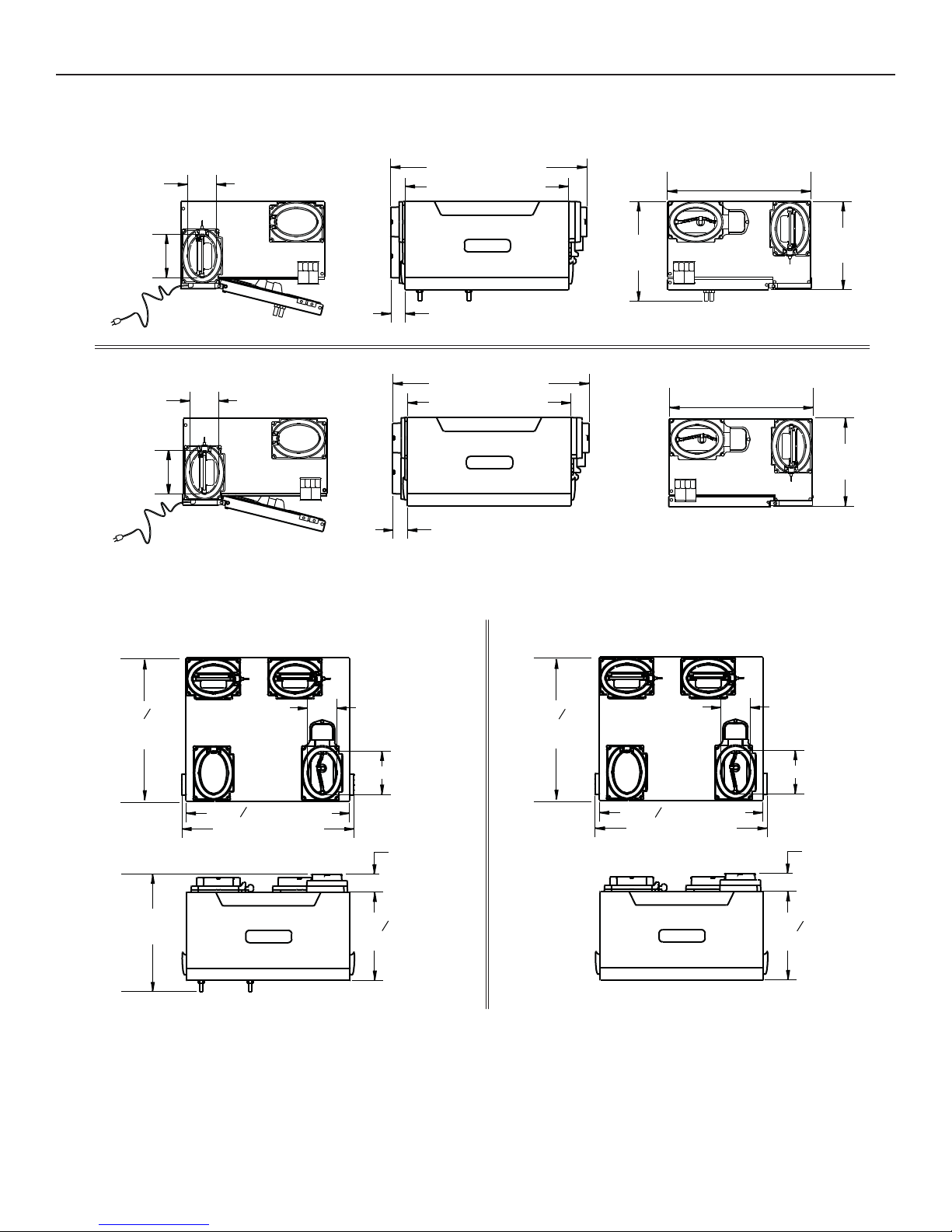
1. TECHNICAL DATA (CONT’D)
1.5 DIMENSIONS
1.5.1 DIMENSIONS FOR PORTS ON SIDES UNITS
4” (102 mm)
6”
(152 mm)
VK0055A
4” (102 mm)
6”
(152 mm)
VK0057A
HRV
1
27 /
16” (688 mm)
9
22 /16” (574 mm)
2” (51 mm)
ERV
1
27 /
16” (688 mm)
9
22 /16” (574 mm)
2” (51 mm)
13¾”
(349 mm)
13
19 /16” (503 mm)
13
19 /
16” (503 mm)
3
12 /16”
(310 mm)
3
12 /16”
(310 mm)
1.5.2 DIMENSIONS FOR PORTS ON TOP UNITS
HRV
13
19 16”
(503 mm)
9
16” (574 mm)
22
23¾” (603 mm)
16¼”
(413 mm)
VK0056A
4’’ (102 mm)
6’’ (152 mm)
2½”
(64 mm)
3
12 16”
(310 mm)
13
19 16”
(503 mm)
16¼”
(413 mm)
VK0058A
ERV
9
22 16” (574 mm)
23¾” (603 mm)
4’’ (102 mm)
6’’ (152 mm)
2½”
(64 mm)
3
16”
12
(310 mm)
1.6 CONTROLS AND LINKAGE POSSIBILITY
MAIN CONTROL
• VT4W
AUXILIARY CONTROLS
• 20-MINUTE PUSH-BUTTON TIMER
• 60-MINUTE CRANK TIMER
• DEHUMIDISTAT
6
LINKAGE POSSIBILITY
• AIR HANDLER INTERLOCK
(USED WITH FORCED AIR SYSTEM)
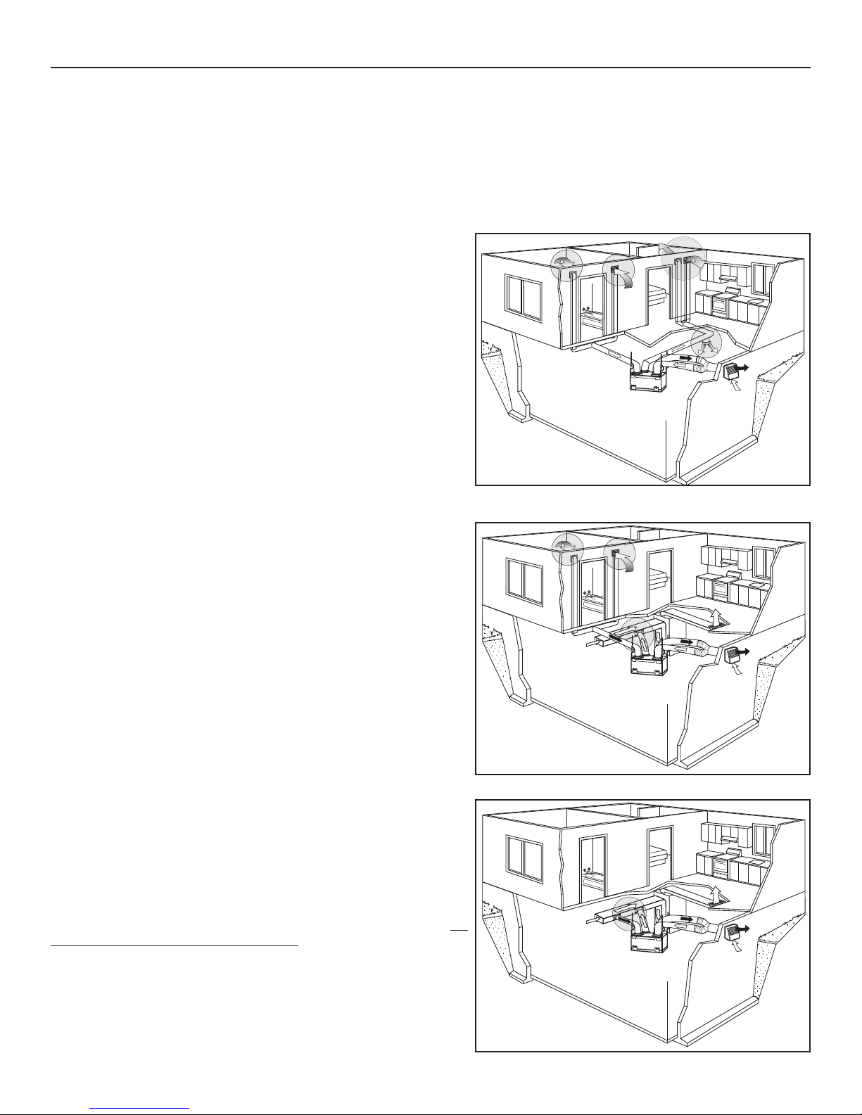
2. TYPICAL INSTALLATIONS
Installations may vary according to the type of unit and the ports configuration (top or sides). Use the following illustrations as guidelines
to help you decide on how the unit will be installed.
All the units should be hung from the joists.
In every case, bathroom fans and a range hood should be used to exhaust stale air. Also, for homes with more than one level, we
recommend one exhaust register at the highest level.
There are 3 installation methods: Fully ducted, Central Draw Point and Simplified Installation.
NOTE: An electrical outlet has to be available within 3 feet of the unit.
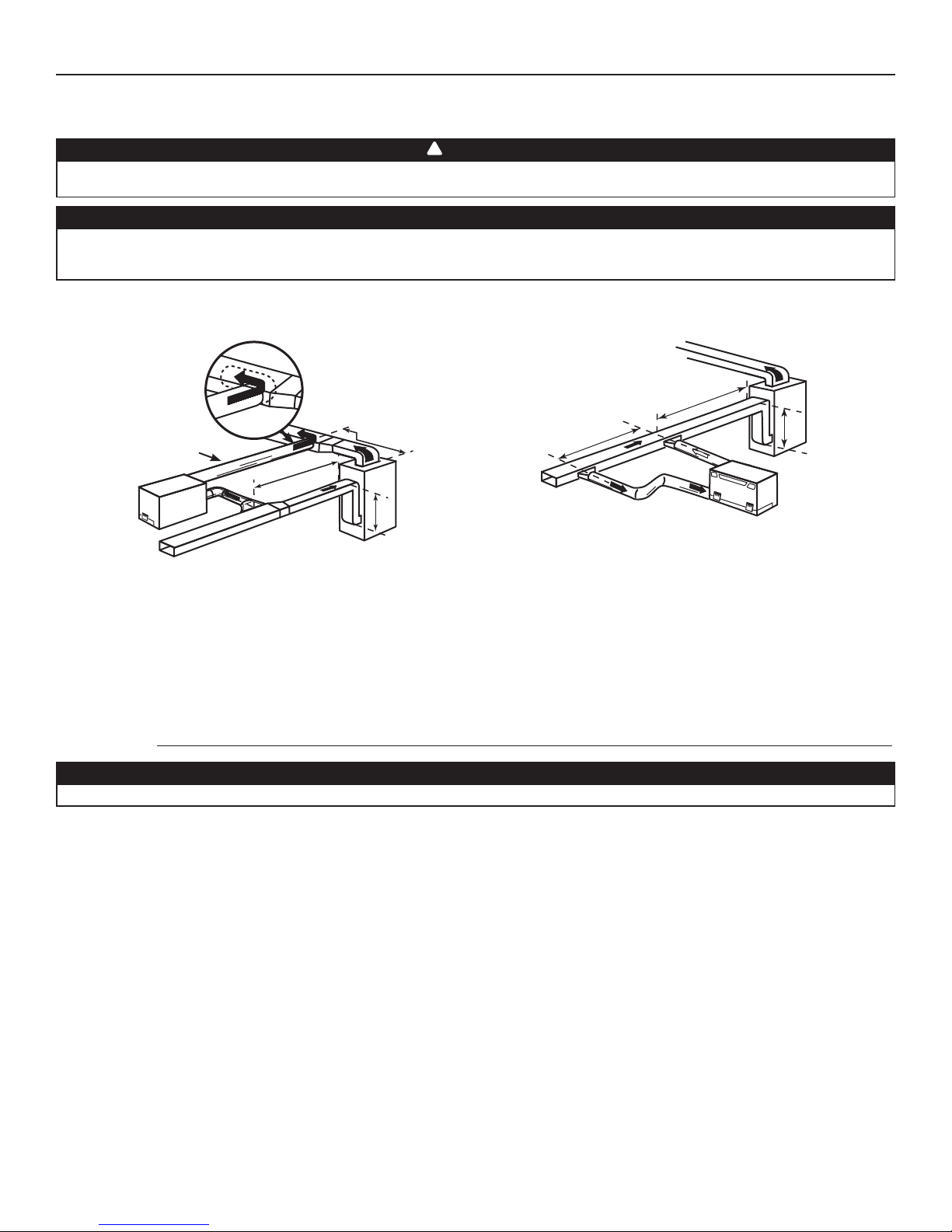
2.1 FULLY DUCTED SYSTEM (PRIMARILY FOR HOMES WITH RADIANT HOT WATER OR ELECTRIC BASEBOARD HEATING)
Stale air coming from the registers located at the highest level of the house
is exhausted to the outside. Fresh air from outside is filtered and supplied by
the register located in the lowest liveable level.
Homes with more than one level require at least one exhaust register at the
highest level.
See figure at right.
2.2 CENTRAL DRAW POINT (CONNECTION TO A FORCED AIR SYSTEM)
Stale air coming from the registers located at the highest level of the house
is exhausted to the outside. Fresh air from outside is filtered and supplied
to the return (plenum) or the supply duct of the forced air unit. See figure
at right.
For this type of installation, it is not essential that the forced air system
blower runs when the unit is in operation, but we recommend it.
NOTE: Home with multiple forced air systems should have one unit on each
system.
2.3 SIMPLIFIED INSTALLATION (CONNECTION TO A FORCED AIR SYSTEM)
Stale air is exhausted to the outside. Fresh air from outside is filtered and
supplied to the return (plenum) or the supply duct of the forced air unit.
See figure at right.
To avoid cross-contamination and achieve the highest efficiencies, the
forced air system blower must always be ON.
NOTE: Home with multiple forced air systems should have one unit on each
system.
VH0055
VH0056
VH0057
7
2. TYPICAL INSTALLATIONS (CONT’D)
ANCHORAGE
WHITEHORSE
JUNEAU
HAY RIVER
YELLOWKNIFE
Prince Rupert
GRANDE PRAIRIE
FORT MCMURRAY
FORT SMITH
EDMONTON
PRINCE ALBERT
SASKATOON
JASPER
KAMLOOPS
CALGARY
PENTICTON
REGINA
LETHBRIDGE
HELENA
VICTORIA
OLYMPIA
WINNIPEG
SALEM
BOISE
BISMARCK
SALT LAKE CITY
SAULT STE MARIE
ST. PAUL
DES MOINES
MADISON
TIMMINS
HARRISBURG
SACRAMENTO
DENVER
TOPEKA
SUDBURY
TORON TO
DETROIT
INDIANAPOLIS
SANTA FE
SPRINGFIELD
OKLAHOMA CITY
PHOENIX
COLUMBUS
NASHVILLE
ATLANTA
BATON ROUGE
AUSTIN
COLUMBIA
RALEIGH
WASHINGTON
OTTAWA
NORTH BAY
VAL-DOR
CHICOUTIMI
HARTFORD
CHIBOUGAMAU
MONTRÉAL
QUEBEC
BOSTON
GOOSE BAY
LABRADOR CITY
SEPT-ILES
MATANE
GASPÉ
BATHURST
ST-JOHN
HALIFAX
CHARLOTTETOWN
ST JOHN’S
RENO
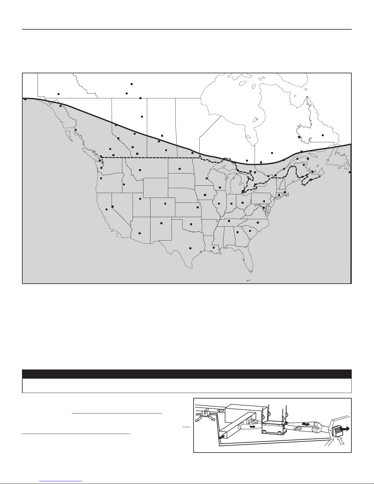
2.4 INSTALLATION FOR ERV UNITS ONLY
2.4.1 GEOGRAPHICAL LOCATION
The ERV units are created to meet specific requirements related to geographical locations. Take a look at the map below; the shaded area
shows the limits where the ERV unit can be installed. However, there is no geographical limitation for installing an HRV unit.
VN0006
NOTE: The ERV unit is designed to assist in the management of humidity introduced into the home.
During cooling season, in extreme humidity conditions, the use of additional dehumidification unit may be required to quickly
remove all excess moisture. During heating season, in extreme dryness conditions, the use of a humidifier may be required if the
indoor air is still too dry.
2.4.2 ERV U
All 3 types of installations can be used in the attic (Fully ducted system, Central Draw Point or Simplified). The example shown below is a
Simplified installation (connection to a forced air system).
NOTE: To get the most of your ERV unit, the ambient temperature around the unit should be conditioned. If the unit has to be installed in
an unconditioned space, the heat gains or losses from the unit and the ducts could increase the operation costs of the unit.
• Due to the potential temperature difference between the attic and the rest of the house, all unit ducts must be insulated.
NITS ATTIC INSTALLATION
• The attic temperature must always be above 0°C (32°F) and under 65°C (149°F).
Stale air is exhausted to the outside. Fresh air from outside is filtered
and supplied to the return (plenum) of the forced air unit. See figure
at right.
To avoid cross-contamination and achieve the highest efficiencies, the
forced air system blower must always be ON.
NOTE: Home with multiple forced air systems should have 1 unit on
each system.
CAUTION
VH0058
8
3. INSTALLATION
J003
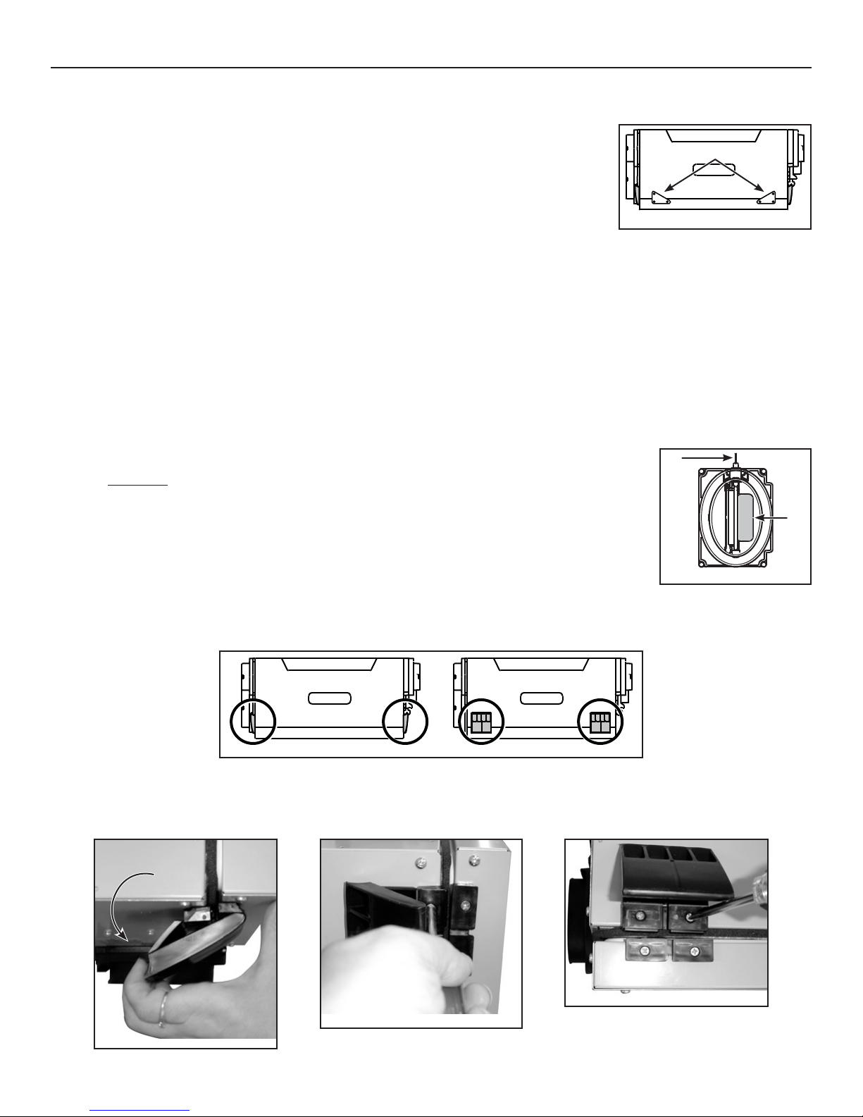
3.1 INSPECT THE CONTENTS OF THE BOX
• Inspect the exterior of the unit for shipping damage. Ensure that there is no damage to the door, door latches, power cord, etc.
• Remove and discard both transport brackets (A) and open the door. Discard the styrofoam
fillers (ERV units only) and remove the hardware kit from the unit. Inspect the interior of the
unit for damage. Ensure that heat or energy recovery core, core filters, insulation, dampers,
etc. are all intact.
VD0183
3.2 LOCATING THE UNIT
Choose an appropriate location for the unit.
• Within an area of the house where the ambient temperature is kept between 18°C (65°F) and 40°C (104°F)
(basement, furnace room, closet, etc.)
• So as to provide easy access to the interior of the unit, for maintenance.
• Close to an exterior wall, so as to limit the length of the insulated flexible duct to and from the unit.
• Away from hot chimneys and other fire hazards.
• Allow for a power source (standard 3-prong grounding outlet).
• For HRV units ONLY: Close to a drain. If no drain is close by, use a pail to collect run-off.
3.3 UNIT PREPARATION
Both HRV and ERV units are equipped with 2 ports having integrated balancing damper. Turn the thumb
screw (B) clockwise to manually open and adjust the damper (C).
HRV UNITS: Set the Fresh air to building port to wide open position, and adjust the Exhaust air to outside port
to 3rd notch.
NOTE: If the unit needs to be balanced, adjust the damper of the Exhaust air to outside port to wide open
position. See Section 7.
ERV UNITS: Set both Fresh air to building port and Exhaust air to outside port to wide open position.
B
V
Port with integrated balancing
damper - Top view
A
C
2
The door latches location can be changed from sides to front of the unit, according to the installation needs.
VD0176
Latches on sides of the unit Latches in front of the unit
To do so, turn the unit upside down. Open the latches an unscrew them from the unit. Install the latches on their new locations.
VB0094
VO0090
VO0089
9
3. INSTALLATION (CONT’D)
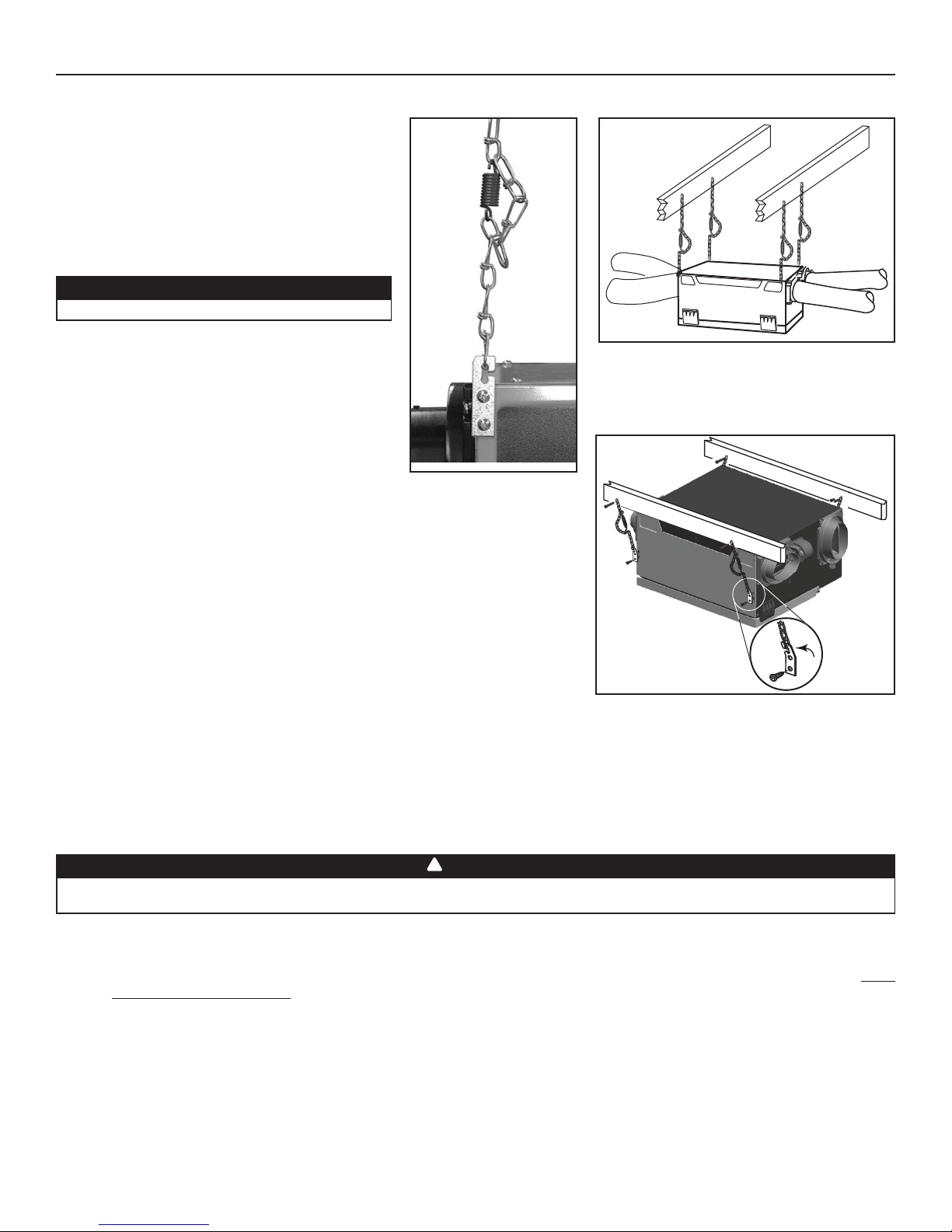
3.4 HOW TO HANG THE UNIT
Hang the unit with the 4 chains, hooks and springs
provided.
CAUTION
Make sure the unit is level.
VD0185
VD0184
If there is not enough space on top of the unit, slightly bend the hooks and install them
lower on the unit. See figure at right.
VD0187
3.5 PLANNING OF THE DUCTWORK
• Keep it simple. Plan for a minimum of bends and joints.
• Keep the length of insulated ducts to a minimum.
• Do not ventilate crawl spaces or cold rooms. Do not attempt to recover the exhaust air from a dryer or a range hood. This would
cause clogging of the filters and recovery module.
• If the house has two floors or more, be sure to plan for at least one exhaust register on the highest lived-in level.
3.6 INSTALLING THE DUCTWORK AND REGISTERS
!
WARNING
Never install a stale air exhaust register in a closed room where a combustion device operates, such as a gas furnace, a gas
water heater or a fireplace.
3.6.1 FULLY DUCTED SYSTEM (AS ILLUSTRATED IN SECTION 2.1)
Stale air exhaust ductwork:
• Install the stale air exhaust registers where the contaminants are produced: Kitchen, living room, etc. Position the registers as far
from the stairway as possible and in such a way that the air circulates in all the lived-in spaces in the house.
• If a register is installed in the kitchen, it must be located at least 4 feet (1.2 m) from the range.
• Install the registers 6 to 12 inches (152 to 305 mm) from the ceiling on an interior wall OR install them in the ceiling.
Fresh air distribution ductwork:
• Install the fresh air distribution registers in bedrooms, dining rooms, living room and basement.
• Keep in mind that the fresh air registers must be located as far as possible from the stale air registers.
• Install the registers in the ceiling OR 6 to 12 inches (152 to 305 mm) from the ceiling on an interior wall. The duct length should be
at least 15’ (4.6 m). (The fresh air will then flow through the room and mix with room air, ensuring a continuous renewed airflow.)
• If a register must be floor installed, direct the airflow up the wall.
10
3. INSTALLATION (CONT’D)
3.6 INSTALLING THE DUCTWORK AND REGISTERS (CONT’D)
3.6.2 CENTRAL DRAW POINT SYSTEM (AS ILLUSTRATED IN SECTION 2.2)
Stale air exhaust ductwork:
Same as for Fully Ducted System, described on point 3.6.1
Fresh air distribution ductwork:
!
WARNING
When performing duct connections, always use approved tools and materials. Respect all corresponding laws and safety
regulations. Please refer to your local building code.
CAUTION
When performing duct connections to the furnace supply duct, this duct must be sized to support the additional airflow
produced by the HRV/ERV. Also, use a steel duct. It is recommended that the HRV/ERV is running when the furnace is in
operation to prevent backdrafting inside HRV/ERV.
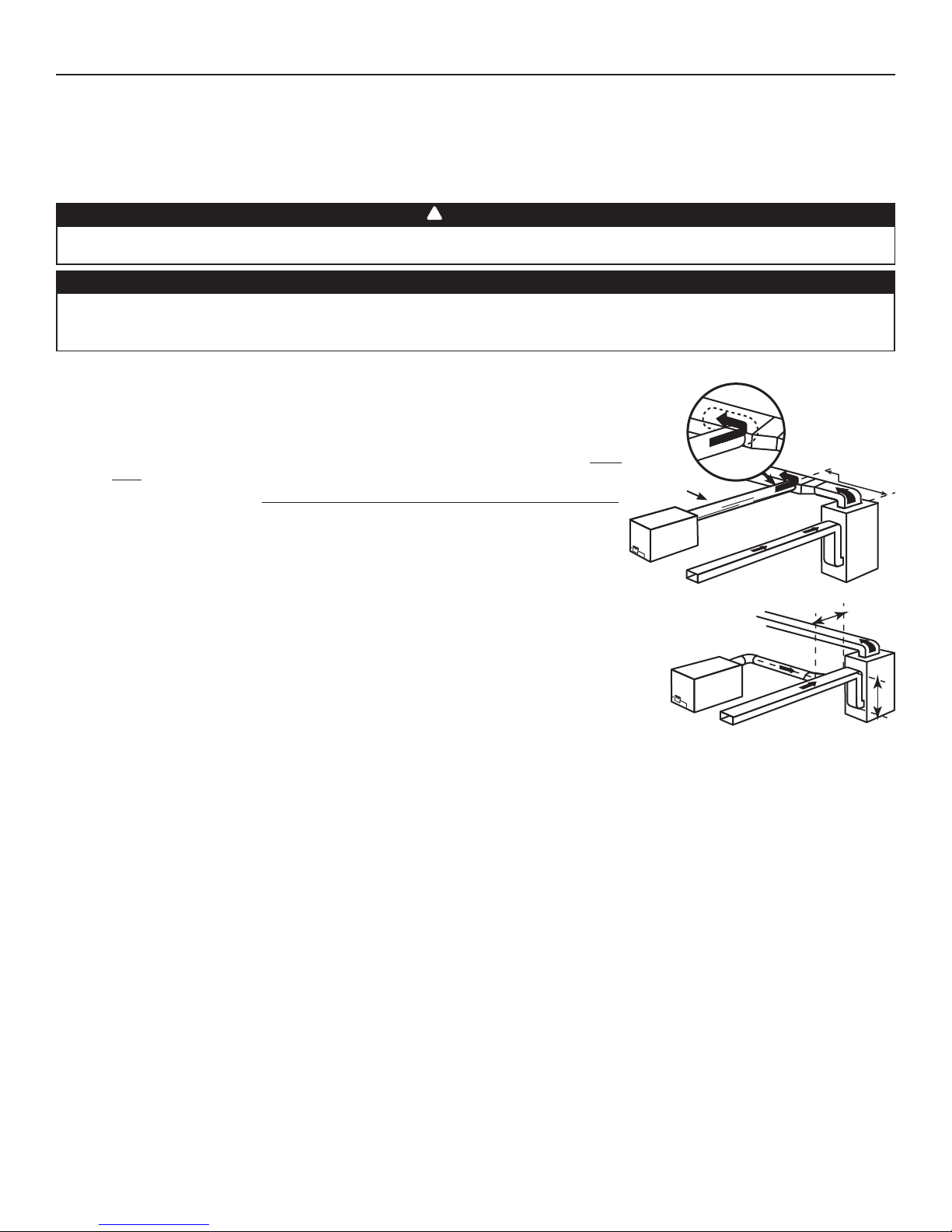
There are 2 methods for connecting the unit to the furnace/air handler:
Method 1: Supply side connection
• Cut an opening into the furnace supply duct at least 18 inches (0.5 m) from the
furnace/air handler.
• Connect this opening to the Fresh air to building port of the HRV/ERV (use steel
duct, see figure at right).
• Make sure the HRV/ERV duct forms an elbow inside the furnace/air handler ductwork.
• If desired, interlock (synchronize) the furnace/air handler blower operation (see
Section 5).
STEEL DUCT
MINIMUM 18"
(0.5 M)
Method 2: Return side connection
VJ0036
• Cut an opening into the furnace return duct not less than 10 feet (3.1 m) from the
furnace/air handler (A+B).
• Connect this opening to the Fresh air to building port of the HRV/ERV(see figure at right).
NOTE: For Method 2, it is not essential that the furnace/air handler runs when the unit is in
operation, but we recommend it. If desired, interlock (synchronize) the furnace/air
handler blower operation (see Section 5).
VJ0035
A
A+B= NOT LESS
THAN 10' (3.1 M)
B
11
3. INSTALLATION (CONT’D)
3.6 INSTALLING THE DUCTWORK AND REGISTERS (CONT’D)
3.6.3 SIMPLIFIED INSTALLATION (AS ILLUSTRATED IN SECTION 2.3)
!
WARNING
When performing duct connections, always use approved tools and materials. Respect all corresponding laws and/or safety
regulations. Please refer to your local building code.
CAUTION
When performing duct connections to the furnace supply duct, this duct must be sized to support the additional airflow
produced by the HRV/ERV. Also, use a steel duct. For a Return-Return installation, the furnace blower must be in operation
when the HRV/ERV is in operation.
There are 2 methods for connecting the unit to the furnace/air handler:
Method 1: Supply-return connection Method 2: Return-return
A+B=
STEEL DUCT
A
MINIMUM 18"
(0.5
M)
INIMUM 3'
M
(0.9 M)
NOT LESS
THAN 10' (3.1 M)
A
B
VJ0038
VJ0037
NOT LESS
A+B=
THAN 10' (3.1 M)
B
Stale air intake:
• Cut an opening into the furnace/air handler return duct not less than 10 feet (3.1 m) from the furnace/air handler (A+B).
• Connect this opening to the Exhaust air from building port of the HRV/ERV.
Fresh air distribution:
• Same instructions as for Method 1 or Method 2, Section 3.6.2.
For Method 2 (Return-return), make sure there is a distance of at least 3 feet (0.9 m) between the 2 connections to the furnace/
air handler.
NOTE: For Method 1, it is not essential to synchronize the furnace blower operation with the unit operation, but we recommend it.
CAUTION
If using Method 2, make sure the furnace/air handler blower operation is synchronized with the unit operation! See Section 5.
12
3. INSTALLATION (CONT’D)
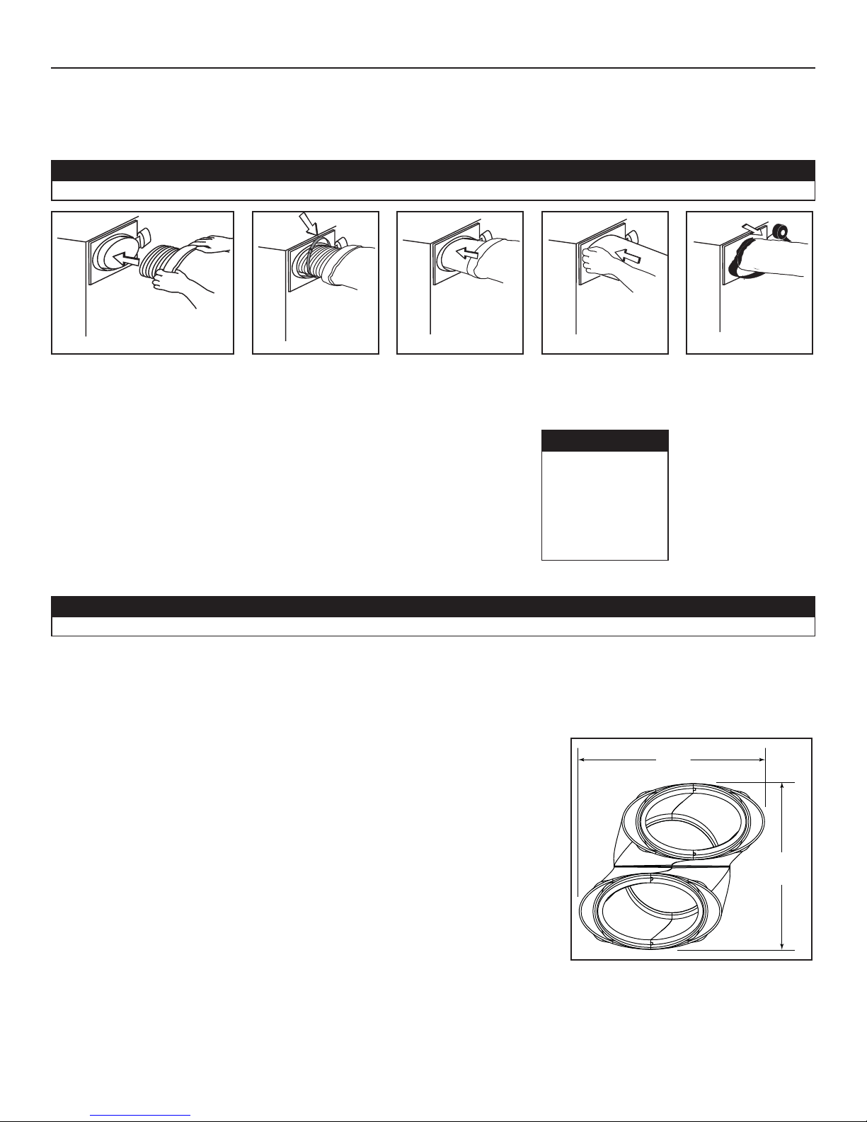
3.7 CONNECTING THE DUCTS TO THE UNIT
Insulated flexible ducts:
Use the following procedure for connecting the insulated flexible ducts to the port of the unit (Exhaust air to outside and Fresh air
from outside ports).
CAUTION
Make sure the balancing dampers are set to their appropriate position before connecting the ducts to the ports. See Section 3.3.
VJ0039
Pull back the insulation to expose
the flexible duct.
VJ0040
Attach the flexible duct
to the port using tie
wrap.
VJ0043
Pull the insulation over
the joint and tuck in
between the inner
and outer rings of the
double collar.
VJ0041
Pull the vapor barrier
over the insulation and
over the outer ring of
the double collar.
CAUTION
Make sure the
vapor barrier on
the insulated ducts
does not tear during
installation to avoid
condensation
within the ducts.
VJ0042
Apply duct tape to
the joint making an
airtight seal. Avoid
compressing the
insulation when pulling
the tape tightly around
the joint.
Compressed insulation
loses its R value and
causes water dripping
due to condensation
on the exterior surface
of the duct.
Rigid ducts:
CAUTION
Do not use screws to connect the rigid ducts to the ports.
Use a small length of flexible duct to connect the rigid duct to the ports in order to avoid vibration transmissions. Use tie-wraps to
perform connections.
3.8 INSTALLING THE TANDEM® TRANSITION* KIT
Use the following procedure for connecting the insulated flexible ducts to the Tandem Transition (Exhaust air to outside and Fresh air from
outside).
NOTE: The joist opening needed to install the Tandem
The maximum height of the Tandem® transition is 8¾”. See tandem Transision end
view at right. If the joists are perpendicular to the ducts, or if the connection to the
exterior hood is in a limited area, your installation will need two exterior hoods
instead of one. In this case, do not use the Tandem Transition kit. See next Section
3.9 INSTALLING 2 EXTERIOR HOODS.
*Patented.
®
transition must be 9¾” minimum.
13
9¾”
248 mm
8¾”
222 mm
VD0118A
3. INSTALLATION (CONT’D)
3.8 INSTALLING THE TANDEM TRANSITION KIT (CONT'D)
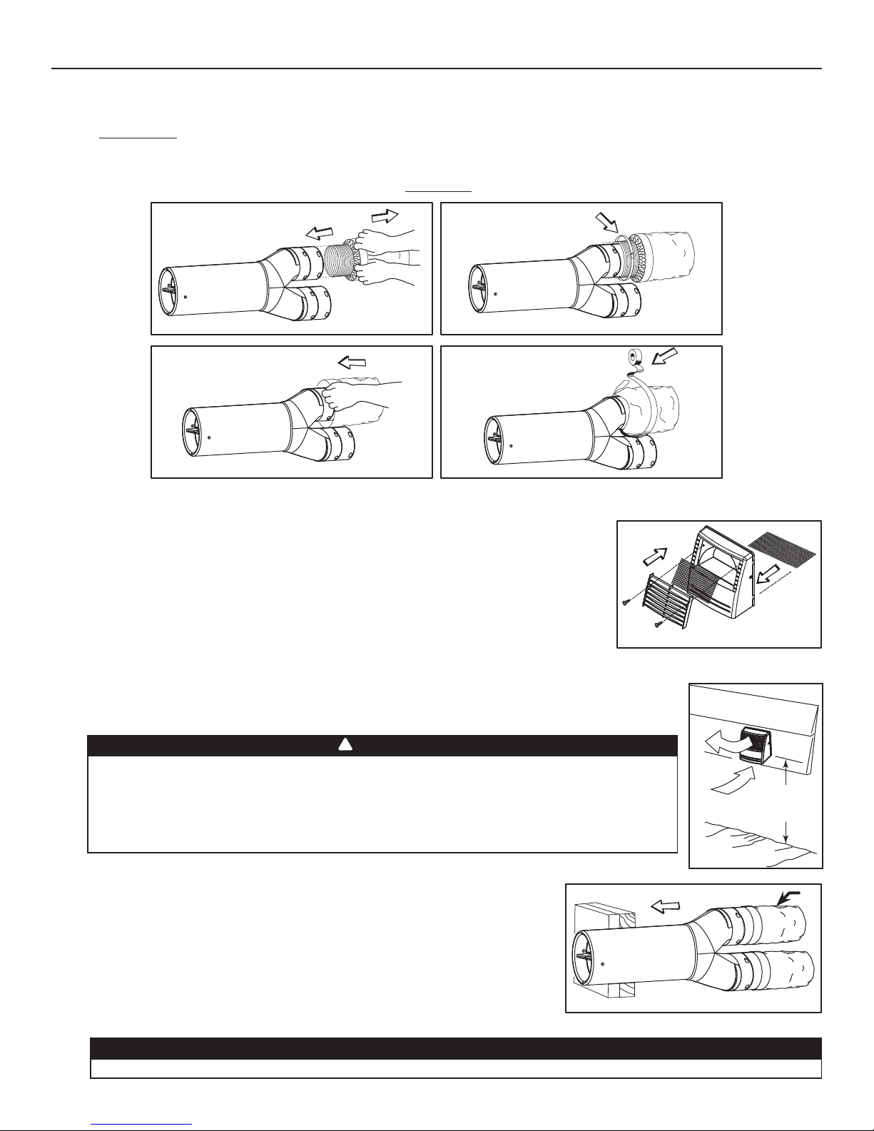
3.8.1 CONNECTION TO TANDEM TRANSITION
1. For each duct, pull back the insulation to expose the interior flexible duct.
2. Connect the interior flexible duct to the smaller part of the Tandem Transition (5” oval) using a tie wrap.
3. Pull the insulation over the joint. Pull the vapor barrier over the insulation.
4. Apply duct tape gently to the joint in order to make an airtight seal. See figures below.
EXHAUST AIR TO OUTSIDE
1
DUCT ON TOP
2
VJ0025
3
VJ0023
VJ0022
4
VJ0024
3.8.2 ASSEMBLING DUAL EXTERIOR HOOD*
Exterior dual hood is coming in separate parts. Using 2 no. 8 x 3/4” screws, assemble the
top metal screen and the plastic grille to the dual exterior hood. Then, slide the bottom metal
screen to the dual exterior hood. See illustration at right.
*Patented.
VO0024
3.8.3 LOCATING THE DUAL EXTERIOR HOOD
The dual exterior hood must be installed at a minimum distance of 18 inches (457 mm) from the ground.
See illustration at right.
!
WARNING
Make sure this hood is at least 6 feet (1.8 m) away (or more, as per applicable building codes or
standards) from sources of contamination such as:
• High efficiency furnace vent
• Any exhaust from a combustion source
• Gas meter exhaust, gas barbecue-grill
• Garbage bin
3.8.4 CONNECTING TANDEM TRANSITION TO THE DUAL EXTERIOR HOOD
18”
(457 mm)
VD0083A
1
1. Using a jig saw, cut a 6” diameter hole in the exterior wall and insert the Tandem
transition through this hole.
The Tandem Transition must be inserted in such a way that the Exhaust air to outside duct will be located on the top.
VD0084
1) EXHAUST AIR TO OUTSIDE DUCT
CAUTION
14
3. INSTALLATION (CONT’D)
3.8 INSTALLING THE TANDEM TRANSITION KIT (CONT'D)
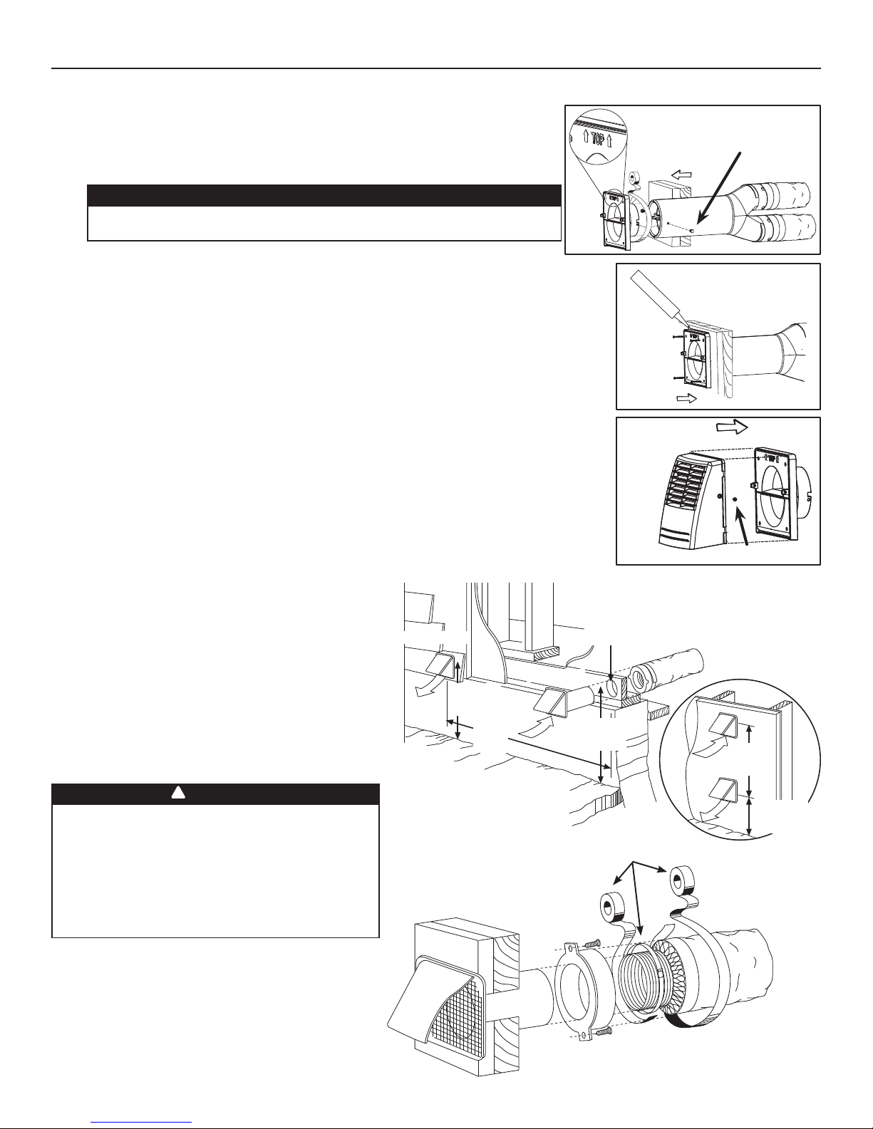
3.8.4 CONNECTING TANDEM TRANSITION TO THE DUAL EXTERIOR HOOD (CONT'D)
2. Join the end of the Tandem Transition to the rear of the exterior backplate. Secure
with 2 Xmas tree pins and seal properly with duct tape.
CAUTION
The exterior backplate must be installed with the word “TOP” pointing
upward.
VD0085
3. Using 4 no. 8 x 1½” screws, mount the the exterior backplate to the exterior wall. Seal the
outline with caulking.
4. Snap the assembled exterior hood on its backplate and secure with 2 provided screws
(no. 8 x 3/4” long).
VD0086
VD0087
XMAS TREE PIN
SCREW
3.9 INSTALLING 2 EXTERIOR HOODS
Choose an appropriate location to install the exterior hoods:
• There must be a minimum distance of 6’ (1.8 m)
between the hoods to avoid cross-contamination
• There must be a minimum distance of 18” (457 mm)
from the ground
!
WARNING
Make sure the intake hood is at least 6 feet (1.8 m)
away (or more, as per applicable building codes or
standards) from any of the following:
• Dryer exhaust, high efficiency furnace vent, central
vacuum vent
• Gas meter exhaust, gas barbecue-grill
• Any exhaust from a combustion source
• Garbage bin and any other source of contamination
Refer to figure at right for connecting insulated ducts to
the exterior hoods. An “Anti-gust intake hood” should be
installed in regions where a lot of snow is expected to fall.
EXHAUST HOOD
(457 MM)
18"
(1.8 M)
6'
INTAKE HOOD
6" Ø
(152 MM)
18"
(457 MM)
TAPE AND DUCT TIE
PTIONAL DUCT
O
LOCATION
6'
(1.8 M)
18"
(457 MM)
VD0028
15
4. CONTROLS
4.1 INTEGRATED CONTROL
All units are equipped with an integrated control, located under the unit, in front of the
electrical compartment. Use the push button (1) to control the unit. The LED (2) will then
shows on which mode the unit is in. Refer to table below.
LED COLOR RESULTS
AMBER UNIT IS ON LOW SPEED
GREEN UNIT IS ON HIGH SPEED
NO LIGHT UNIT IS OFF OR CONTROLLED BY A MAIN CONTROL
No li ght OFF or remote controled
Amber light LOW speed
Green ligh HIGH speed
Blinking light See User Manual
Sans lumière Arrêté ou contrôlé
par contrôle mural
Lumière ambre Basse vitesse
Lumière verte Haute vitesse
Clignotant Voir guide d’utilisation
VD0182
If a problem occurs during the unit operation, its integrated control LED (2) will blink. The color of the blinking light depends on the type of
error detected. Refer to Section 11 TROUBLESHOOTING on page 25 for further details.
WARNING
Risk of electric shock. Before performing
any maintenance or servicing, always
disconnect the unit from its power source.
CAUTION
Unscrew both screws to open the electrical
compartment. To completely remove, detach
from its retention wire inside.
12
AVERTISSEMENT
Danger d’électrocution. Débranchez
toujours l’appareil avant d’entreprendre
des travaux d’entretien ou de réparation.
ATTENTION
Dévisser les deux vis pour ouvrir le compartiment
électrique. Pour retirer complètement, le
détacher de son fil de rétention intérieur.
4.1.1 B
OOT SEQUENCE
The unit boot sequence is similar to a personal computer boot sequence. Each time the unit is plugged after being unplugged, or
after a power failure, the unit will perform a 30-second booting sequence before starting to operate. During the booting sequence,
the integrated control LED will light GREEN or AMBER for 5 seconds, and then will shut off for 2 seconds. After that, the LED will
light RED for the rest of the booting sequence. During this RED light phase, the unit is checking and resetting the motorized damper
position. Once the motorized damper position completely set, the RED light turns off and the booting sequence is done.
NOTE: No command will be taken until the unit is fully booted.
4.2 ELECTRICAL CONNECTION TO OPTIONAL WALL CONTROLS
For more convenience, this unit can also be controlled using an optional main wall control.
NOTES: 1. The integrated control must be turned OFF to use an optional main control.
2. If an optional auxiliary control is used, if activated, this auxiliary control will override the optional main control.
!
WARNING
Always disconnect the unit before making any connections. Failure in disconnecting power could result in electric shock or
damage of the wall control or electronic module inside the unit.
CAUTION
Never install more than one optional main wall control per unit. Make sure that the wires do not short-circuit between
themselves or by touching any other components on the wall control. Avoid poor wiring connections. To reduce electrical
interference (noise) potential, do not run wall control wiring next to control contactors or near light dimming circuits, electrical
motors, dwelling/building power or lighting wiring, or power distribution panel.
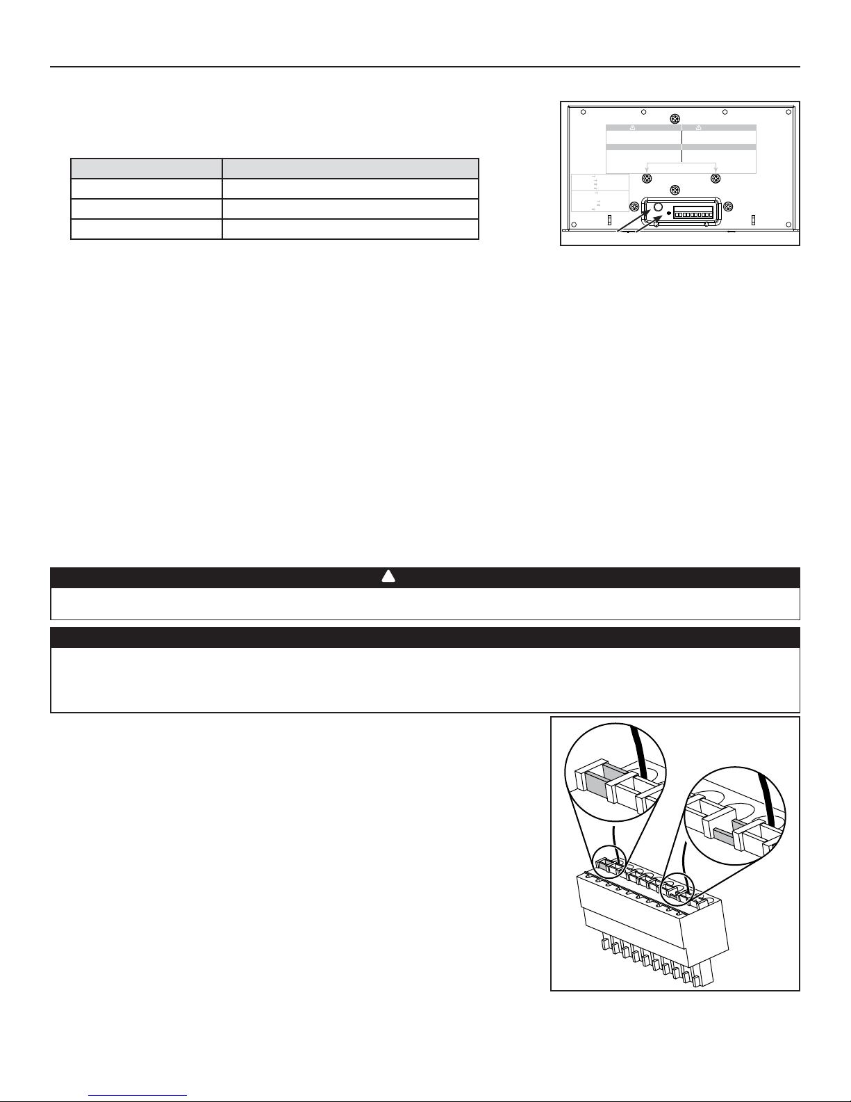
Use the terminal connector included in the installation kit to perform the electrical
connection for main and optional wall controls. Check if all wires are correctly inserted in
their corresponding holes in the terminal block. (A wire is correctly inserted when its orange
receptacle is lower than another one without wire. On illustration at right, wire A is correctly
inserted, but not wire B.)
B
A
VE0272
16
 Loading...