

Page 1
USER GUIDE
READ AND SAVE THESE INSTRUCTIONS
INSTALLER: LEAVE THIS MANUAL WITH HOMEOWNER
* These products earned the ENERGY STAR
®
by meeting strict energy efficiency guidelines
set by Natural Resources Canada and
the US EPA. They meet ENERGY STAR
requirements only when used in Canada.
99528507A
VB0192
VB0190
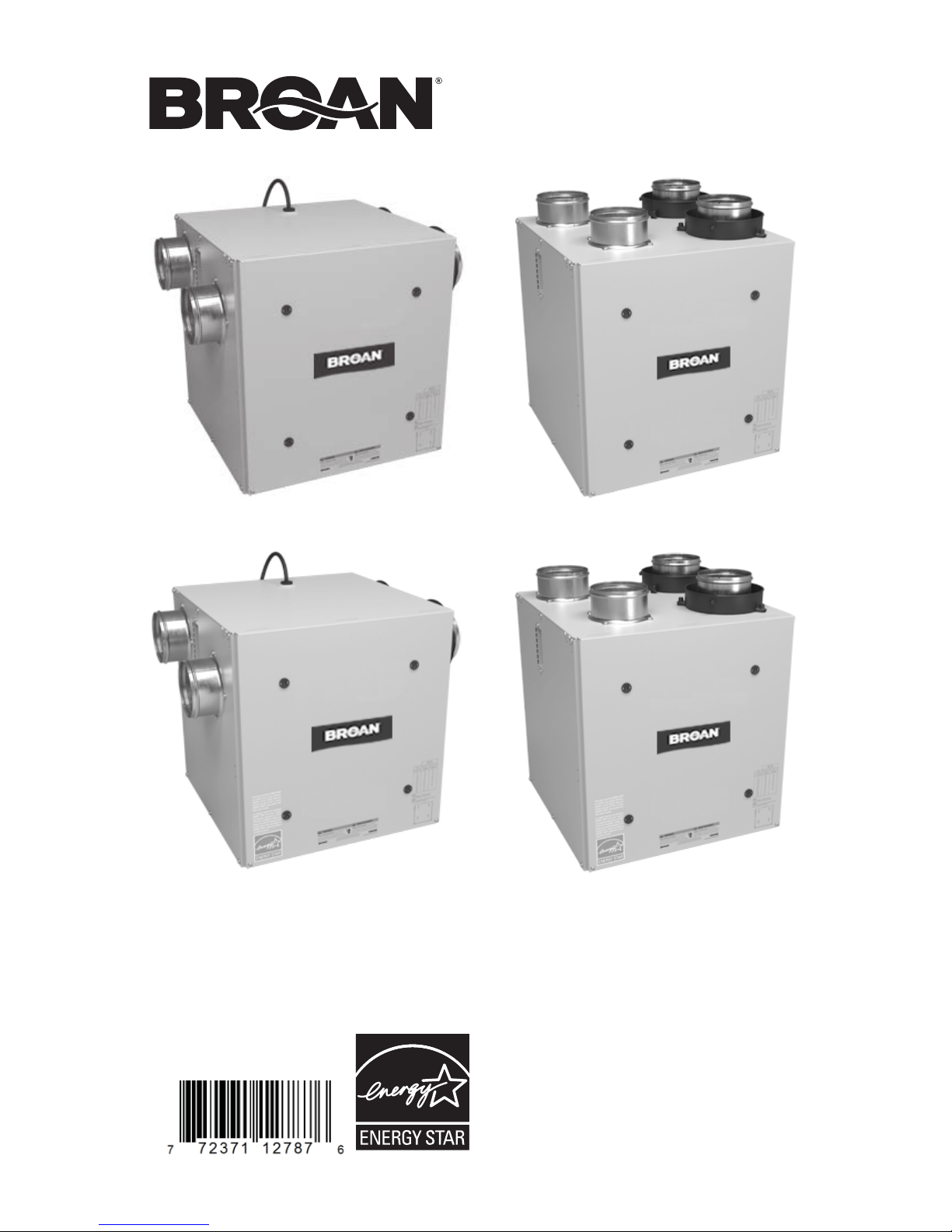
Model ERV70S (side ports) Model ERV70T (top ports)
VB0193
VB0191
Model HRV70SE*
(side ports)
Model HRV70TE* (top ports)
Register your product online at: www.broan.com/register
Page 2
Congratulations!
You have made an excellent choice! The operating principle of your Heat Recovery
Ventilator or your Energy Recovery Ventilator will give you personal comfort you
have never known before.
We have prepared this User Guide especially for you. Please read it carefully to
ensure you obtain full benefit from your unit. Over the coming months, you will
increasingly appreciate the feeling of living in a more comfortable house.
Please take note that this manual uses the following symbols to emphasize
particular information:
WARNING
Identifies an instruction which, if not followed, might cause serious
personal injuries including possibility of death.
!
CAUTION
Identifies an instruction which, if not followed, may severely damage the
unit and/or its components.
NOTE: Indicates supplementary information needed to fully complete an instruction.
We welcome any suggestions you may have concerning this guide and/or the unit,
or ways to better serve you. Please forward all correspondence at the address below:
Broan-NuTone LLC
Indoor Air Quality Mkt.
926 W. State St.,
Hartford, WI 53027
CAUTION
Make sure at all times that the outside intake and exhaust hoods are free
from any snow during the winter season. It is important to check your unit
during a big snow storm, so it doesn’t draw in any snow. If this is the case,
please operate the unit in recirculation mode, or turn it OFF for a few hours.
Do not use your unit during construction or renovation of your house or
when sanding drywall. This type of dust may damage your system.
Since the electronic control system of the unit is incorporated with a
microprocessor, it may not operate correctly because of external noise
or very short power failure. If this happens, unplug the unit and wait
approximately 10 seconds. Then, plug the unit in again.
2
Page 3

TABLE OF CONTENTS
3
When the outside temperature is below 23°F (-5°C), recovery of heat or energy
creates frost in the core.
To maintain its proper operation, the unit is programmed to defrost the recovery
core. The defrost frequency varies according to the outside temperature.
During the defrost cycle, the unit shifts to maximum speed and the dampers close.
After defrosting, the unit returns to the operating mode selected by the user.
1. DEFROSTING MODE
1. DEFROSTING MODE . . . . . . . . . . . . . . . . . . . . . . . 3
2. C
ONTROLS. . . . . . . . . . . . . . . . . . . . . . . . . . . 4-6
2.1 INTEGRATED CONTROL . . . . . . . . . . . . . . . . . . . . . . . . 4
2.2 OPTIONAL MAIN CONTROL VT4W . . . . . . . . . . . . . . . . . . . 5
2.3 OPTIONAL AUXILIARY CONTROLS . . . . . . . . . . . . . . . . . . . . 6
2.3.1 20-MINUTE LIGHTED PUSH BUTTON . . . . . . . . . . . . . . . . . . . 6
2.3.2 60-MINUTE CRANK TIMER . . . . . . . . . . . . . . . . . . . . . . . 6
2.3.3 DEHUMIDISTAT . . . . . . . . . . . . . . . . . . . . . . . . . . . . . 6
3. MAINTENANCE . . . . . . . . . . . . . . . . . . . . . . . . . .7-9
3.1 QUARTERLY MAINTENANCE . . . . . . . . . . . . . . . . . . . . . . . 9
3.2 ANNUAL MAINTENANCE . . . . . . . . . . . . . . . . . . . . . . . . 9
4. TROUBLESHOOTING . . . . . . . . . . . . . . . . . . . . . . . 9-10
Page 4

4
2. CONTROLS
2.1 INTEGRATED CONTROL
BOOTING SEQUENCE
The unit booting sequence is similar to a personnal computer boot sequence.
Each time the unit is plugged after being unplugged, or after a power failure, the
unit will perform a 30-second booting sequence before starting to operate.
During the booting sequence, the integrated control LED (2 in illustration
below) will light GREEN for 5 seconds, and then will turn RED. During this
RED light phase, the unit is checking and resetting the motorized damper
position. Once the motorized damper position completely set, the RED light
turns off and the booting sequence is done.
NOTE: No command will be taken until the unit is fully booted.
All units are equipped with an integrated control,
located on the upper left side of the unit.
Use the push button (1) to control the unit.
The LED (2) will then show on which mode the
unit is in.
PRESS ON PUSH BUTTON LED COLOR RESULTS
ONCE AMBER
UNIT IS ON LOW SPEED
TWICE GREEN
UNIT IS ON HIGH SPEED
THREE TIMES NO LIGHT
UNIT IS OFF
If a problem occurs during the unit operation, its integrated control LED (2)
will blink. The color of the blinking light depends on the type of error detected.
Refer to Section 4 Troubleshooting on last page for further details.
NOTE: WHEN USING MAIN CONTROL, THE INTEGRATED CONTROL
MUST BE TURNED OFF.
VE0220
1
2
Refer to table below to see how to operate the unit using its integrated control.
Page 5

5
2. CONTROLS (CONT’D)
2.2 OPTIONAL MAIN CONTROL VT4W
For more convenience, this unit can also be controlled using the optional main
wall control VT4W. Only one VT4W can be connected to the unit.
NOTES: 1. The integrated control must be turned OFF to use the optional
main control VT4W.
2. If an optional auxiliary control is used, if activated, this auxiliary
control will override the VT4W control operation.
INTERMITTENT
MAX
MIN
VC0070
VT4W
When power is applied for the first time or after a
power failure, this control is in OFF mode. Activate
the push button; the light indicator will show clearly in
which operating mode the unit is.
LIGHT INDICATOR
COLOR
MODE SUGGESTED USE
GREEN INTERMITTENT
Select this mode when you are away
from the house for a few days. Also,
when you deem the inside air is too
dry in heating season, or too humid
during cooling season. In this mode,
the unit is OFF for 40 minutes per
hour and ventilates at minimum speed
the remaining 20 minutes of the hour.
YELLOW MIN
Minimum ventilation speed for normal
daily operation.
RED MAX
Maximum ventilation speed for excess
pollutants and humidity (parties,
odors, smoke, etc.)
N
O LIGHT OFF
Turn off the unit before performing
maintenance.
Page 6

2. CONTROLS (CONT’D)
Contrary to the optional main control, up to 5 optional auxiliary controls
can be connected to the same ventilation unit.
2.3 OPTIONAL AUXILIARY CONTROL
2.3.1 20-MINUTE LIGHTED PUSH BUTTON
Press once on its center (A) to activate the push
button. The ventilation unit will exchange air with
the outside on high speed for a 20-minute period,
and the indicator (B) will light up. To stop activation
before the end of the 20-minute cycle, press one
more time. The unit will get back to its previous
setting.
NOTE: Control appearance may vary.
VC0084
ON
A
B
2.3.2 60-MINUTE CRANK TIMER
This control makes the unit operate at high speed
for periods varying from 10 to 60 minutes.
OFF
10
Turn
Past
V
C00
17
20
30
40
50
60
MINUTES
HOLD
2.3.3 DEHUMIDISTAT
Adjust knob to the desired maximum
indoor humidity level.
6
CAUTION
Do not select a humidity level
below 30%. This could lead to
excessive dryness in the air
causing discomfort for the
occupants.
O
F
F
70%
60%
50%
40%
30%
25%
20%
DEHUMIDISTAT
VC0140
%
R
E
L
A
T
I
V
E
H
U
M
I
D
I
T
Y
C
O
M
F
O
R
T
Z
O
N
E
Page 7

7
WARNING
Risk of electric shock. Before performing any maintenance, always turn
off and disconnect the unit from its power source. Sharp edges may be
present. When cleaning the unit, it is recommended to wear safety glasses
and gloves.
!
3. MAINTENANCE
Refer to illustration at right to identify the inner parts
of your unit.
1. Heat or energy recovery core
2. Core filters
3.1 QUARTERLY MAINTENANCE
VD0005
Turn the unit OFF and unplug it.
VD0244
1
2
Remove the unit door by following these steps:
A. Remove both door lower machine screws no. 8-32 x 1” (1) and set
aside.
B. Open (2) and lift out the door (3).
VO0191
AB
1
2
3
Page 8

8
3. MAINTENANCE (CONT’D)
3.1 QUARTERLY MAINTENANCE (CONT’D)
Slide out both filters (1)
and recovery core (2)
from the unit.
Clean the inside walls of
the unit with a clean damp
cloth, then wipe with a
clean dry one.
Remove dust on filters
and on core using a
vacuum cleaner and a
soft brush attachment.
Wash both core filters under
lukewarm water with mild
soap. Rinse thoroughly
and let dry completely before reinstalling on the core.
Slide the core and the cleaned filters into the unit.
Reinstall the door. Secure it with both mechanical screws no. 8-32 x 1”
previously removed and plug the unit.
NOTE: The unit will return to its previous setting after a 30-second
delay for boot sequence.
VD0243
1
2
CAUTION
Follow the instructions on the core label to reinstall it correctly.
Page 9

9
3. MAINTENANCE (CONT’D)
3.2 ANNUAL MAINTENANCE
Do the same operations as the Quarterly Maintenance (Section 3.1), and
clean the recovery core as follows (refer to the core label):
HRV units: Soak the heat recovery core in a mixture of lukewarm water
and mild soap. Rinse thoroughly. Shake the core to remove excess water
and let it dry.
ERV units: Remove the dust on the core using a vacuum cleaner and a
soft brush attachment.
All units: After reinstalling the core, core filters and the unit door, then
clean the exterior hoods.
4. TROUBLESHOOTING
If the unit does not work properly, reset the unit by unplugging it for one minute
and then replug it. If it is still not working properly, refer to table on next page.
WARNING
Shock hazard. Never open the electronic box. No user-serviceable parts
inside. There is a fuse on the electronic board. Never attempt to replace it.
Refer servicing to qualified service personnel.
!
Page 10

10
4. TROUBLESHOOTING (CONT’D)
PROBLEMS YOU SHOULD TRY THIS
1 Unit does not work. • See if the unit is plugged in.
• See if the unit is receiving power from the
house circuit breaker or fuse.
2 Condensation on windows (air
too humid).
•
See Controls section on pages 4 to 6.
• Leave curtains half-open to allow air
circulation.
• Store all firewood in a closed room with a
dehumidifier or in a well ventilated room, or
store the wood outside.
• Do not adjust the thermostat of your heating
system below 64°F (18°C).
3 Inside air too dry (on cold
season).
• See Controls section on pages 4 to 6.
• Temporarily use a humidifier.
4 Air too cold at the air supply
grille (on cold season).
• Check if the exterior hoods are not blocked,
specifically the exhaust air to outside one.
• See Controls section on pages 4 to 6.
• Install a duct heater.
5 The LED of the integrated
control is blinking GREEN.
• There is a problem with the thermistor.
The unit is still working, but will defrost
frequently. Contact your installer.
6 The LED of the integrated
control is blinking AMBER.
• There is a problem with the motorized
damper. The unit is OFF. For a 2½-hour
period, the unit will try to reset the damper
at every 30 minutes. After 2½ hours, if the
problem is not solved, the unit stops trying
to reset damper.
• Contact your installer.
7 The integrated defrost control
push-button does not work.
• The 30-second boot sequence is not
completed, see step 2.1 Integrated Control
on page 4.
If the problem is still not solved, call your installer or the nearest approved Service
Center. Also, you can reach our Customer Service Department or Technical
Support listed below:
Broan-NuTone LLC
• Technical Support
Telephone: 1-800-637-1453
Fax: 1-262-673-8709
• Customer Service Department
Telephone: 1-800-558-1711
Fax: 1-800-356-5862
 Loading...