


Alternator Identification
Briggs & Stratton engines are equipped with a number of different alternator systems to meet the requirements of equipment manufacturers. For example, a large lawn tractor with accessories may require a 16 amp regulated system, whereas a snow thrower with a single headlight requires an AC Only system. Knowing the type of alternator system an engine is equipped with is important, particularly when an engine is being replaced.
Briggs & Stratton alternator systems are easily identified by the color of the stator output wire(s) and the connector.
Stator Output Wire(s)
And Connector
(typical)
AC Only
ONE BLACK LEAD FROM ENGINE (STATOR)
TO EQUIPMENT |
WHITE CONNECTOR |
|
HARNESS |
||
OUTPUT LEAD |
||
|
·14 Volts AC for lighting circuit.
·One black lead from stator.
·White connector output lead.
DC Only
ONE RED LEAD
FROM ENGINE
(STATOR )
RED
CONNECTOR

 DIODE TO EQUIPMENT

HARNESS
·3ampDCunregulatedforchargingbattery.
·One red lead from stator.
·Diode encased at connector.
·Red connector output lead.
1

|
Dual Circuit |
BLACK LEAD |
|
|
RED LEAD |
|
AC OUTPUT |
|
DC OUTPUT |
|
|
RED AND BLACK |
|
|
|
LEADS FROM ENGINE |
|
|
|
(STATOR) |
|
|
|
DC CHARGING CIRCUIT |
|
|
|
RED LEAD |
|
|
|
|
|
WHITE |
|
TO EQUIPMENT |
|
CONNECTOR |
|
|
|
|
|
HARNESS |
WHITE LEAD |
|
|
|
|
|
|
|
AC FOR LIGHTS |
|
|
·3 amp DC unregulated for charging battery (ONE red lead from stator).
·14 Volts AC for lighting circuit (ONE black lead from stator).
·Diode encased at connector.
·White connector with two pin terminals.
Tri-Circuit
|
|
|
|
|
|
|
|
ONE BLACK LEAD |
|
|
|
|
|
|
|
|
FROM ENGINE |
TO EQUIPMENT |
|
|
|
|
|
|
|
(STATOR) |
5 AMPS DC (-) |
|
|
|
|||||
HARNESS |
TWO DIODES ENCASED |
|||||||
|
|
TO LIGHTS |
|
IN WIRE HARNESS |
||||
|
|
WHITE LEAD |
|
|||||
|
|
|
|
|
||||
|
|
|
|
|
|
|
|
|
|
|
|
|
|
|
|
|
|
|
|
|
|
|
|
|
|
|
GREEN RED LEAD 5 AMPS DC (+) CONNECTOR
TO BATTERY AND CLUTCH CIRCUIT
·10 amp AC.
·One black lead from stator.
·Green connector.
·Two diodes encased in wire harness.
·Red and white output leads.
|
5 or 9 amp Regulated |
TO |
ONE BLACK LEAD |
EQUIPMENT |
|
FROM ENGINE |
|
HARNESS |
(STATOR) |
|
|
|
RED |
|
|
CONNECTOR |
|
GREEN
CONNECTOR
YELLOW
WIRE
REGULATOR 
RECTIFIER
·5 or 9 amp DC regulated for charging battery.
·Alternator output (5 or 9 amp) is determined by flywheel alternator magnet size.
·Uses same stator as Tri-Circuit system.
·One black lead from stator.
·Green connector.
10 or 16 amp Regulated
TO EQUIPMENT
HARNESS
RED CONNECTOR
OUTPUT LEAD
ONE RED |
|
TWO BLACK LEADS |
||
|
FROM ENGINE |
|||
LEAD |
|
|||
|
(STATOR) |
|||
|
|
|||
|
|
|
|
|
YELLOW
REGULATOR TWO YELLOW LEADS CONNECTOR RECTIFIER
·10 or 16 amp DC regulated for charging battery.
·Alternatoroutputisdeterminedbytheflywheel alternator magnet size.
·10 and 16 amp system use the same stator, color coding and regulator-rectifier.
·Two black leads from stator.
·Yellow connector with two pin terminals.
·Two yellow leads to regulator-rectifier.
·One red lead from regulator-rectifier to red connector output lead.
493219 Regulator/Rectifier
Used With Charge Indicator Circuit
TO EQUIPMENT
HARNESS RED WIRE AND RAISED
RIB INDICATES DC OUTPUT
BLUE WIRE
CHARGING INDICATOR
WHITE
CONNECTOR
|
TWO YELLOW |
|
493219 REGULATOR |
LEADS |
YELLOW |
RECTIFIER |
|
CONNECTOR |
·Uses same stator as 10 and 16 amp system.
·DC output the same as 10 or 16 amp system.
·Charge indicator light and wiring supplied by equipment manufacturer.
·Red DC output wire to white connector.
·Blue charge indicator wire to white connector.
2

Engine/Alternator Replacement Information
With the exception of the AC Only alternator, all of the alternator systems referred to in this book have a battery as part of the electrical system.
There are specialized applications that use an alternator without a battery. An example would be certain generators or welders that use alternator output to excite an electrical field. For theequipment tofunction, the alternator output must be very evenly matched to the equipment requirements. When replacing an engine in these applications, the alternator must be the same as the original.
Replacing Briggs & Stratton Engines
When replacing an older Briggs & Stratton engine on apiece ofequipment witha newerBriggs & Stratton engine, sometimes the newer engine has an alternator system different from the alternator system on the original engine. This means that the output connector on the replacement engine is not compatible with the original wiring harness on the piece of equipment. For example, the original engine may have been equipped with a Dual Circuit system and the replacement engine is equipped with a regulated system. We can integrate the two systems by making an adapter harness from readily available parts.
Generally an unregulated DC system (DC Only, Dual Circuit) should not be used to replace a regulated system because alternator output may not be sufficient for equipment requirements. However, because the equipment requirements are usually much less on an unregulated DC system, a regulated system may be used as a replacement. The regulator/rectifier prevents the battery from being over charged.
NOTE: The AC Only, DC Only, Dual Circuit, Tri-Circuit as well as the 5 and 10 amp regulated systems use flywheels with small alternator magnets. The 9 and 16 amp regulated systems use flywheels with the large alternator magnets. See figure below for magnet sizes.
ALTERNATOR MAGNETS
*Small Magnet |
7/8” x 11/16” |
|
(22mm x 18mm) |
|
|
*Large Magnet |
1-1/16” x 15/16” |
|
(27mm x 24mm) |
|
|
* V Twin Alternator Magnet Size: Small 7/8” x 21/32” (22 mm x 17 mm) Large 7/8” x 29/32” (22 mm x 23 mm)
3
The following are alternator replacement combinations which require an adapter harness. All of the necessary components are shown.
1.Original engine equipped with AC Only alternator. Replacement engine equipped with Dual Circuit alternator.
Modify 393362 harness supplied with replacement engine by removing red DC wire. Then, splice 393537 connector into white AC wire and connect to equipment harness.
|
AC WIRE |
EQUIPMENT |
|
DUAL CIRCUIT CONNECTOR |
(WHITE) |
HARNESS |
|
|
|
||
(FROM ENGINE) |
393362 |
|
|
|
|
||
|
HARNESS |
|
|
AC |
|
|
|
BLACK |
|
|
|
DC |
|
|
|
RED |
SPLICE |
|
|
|
|
||
RIB |
|
393537 |
|
RIB |
CONNECTOR |
||
|
|||
|
|
(GREEN) |
2.Original engine equipped with DC Only alternator. Replacement engine equipped with Dual Circuit alternator.
Modify 393362 harness supplied with replacement engine by removingwhite AC wire. Then,splice 393537 connector into red DC wire and connect to equipment harness.
DUAL CIRCUIT CONNECTOR |
393362 |
DC WIRE |
EQUIPMENT |
|
(FROM ENGINE) |
HARNESS |
|||
HARNESS |
(RED) |
|||
|
|
|||
AC |
|
|
|
|
BLACK |
|
|
|
|
DC |
|
|
|
|
RED |
|
|
|
|
RIB |
RIB |
SPLICE |
393537 |
|
|
|
CONNECTOR |
||
|
|
|
||
|
|
|
(GREEN) |
|
|
4 |
|
|

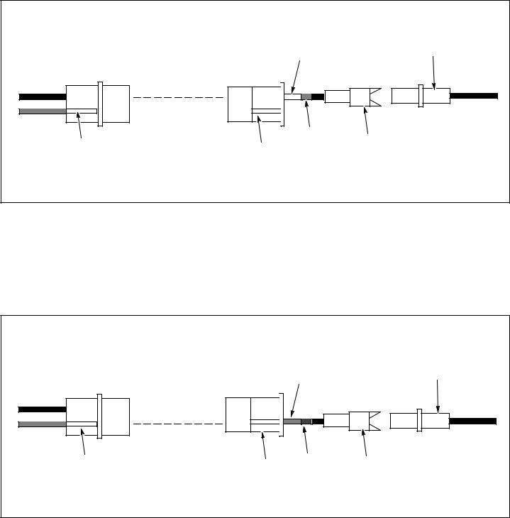
3.Original engine equipped with Dual Circuit alternator.
Replacement engine equipped with 5, 9, 10 or 16 amp regulated system.
Modify 393422 harness supplied with replacement engine by splicing in 399916 connector assembly. Connect to equipment harness.
|
399916 CONNECTOR |
|
OUTPUT CONNECTOR |
ASSEMBLY |
EQUIPMENT |
|
HARNESS |
|
FROM REGULATOR |
|
|
|
|
|
|
SPLICE |
|
393422 |
RIB |
RIB |
HARNESS |
|
|
4.Original engine equipped with Tri-Circuit alternator.
Replacement engine equipped with 5, 9, 10 or 16 amp regulated system.
Modify 393422 harness supplied with replacement engine by splicing into charging circuit wireand lighting circuit wire in equipment harness. NOTE:THE DIODES MUST BE REMOVED FROMTHE EQUIPMENT HARNESS.
Diodes Must Be Removed From Equipment Harness |
|
OUTPUT CONNECTOR |
|
FROM REGULATOR |
|
SPLICE |
LIGHTING CIRCUIT WIRE |
|
|
|
EQUIPMENT |
|
HARNESS |
393422 |
|
HARNESS |
CHARGING CIRCUIT WIRE |
|
|
5

5.Original engine equipped with Dual Circuit alternator. Replacement engine equipped Tri-Circuit alternator.
Discard 392606 diode harness supplied with new engine. Install 491546 regulator/rectifier. Add 393422 harness and modify by splicing in 399916 connector assembly. Connect to equipment harness.
|
|
399916 CONNECTOR |
OUTPUT CONNECTOR |
|
ASSEMBLY |
|
|
|
FROM ALTERNATOR |
|
SPLICE |
|
|
|
|
393422 |
RIB |
|
RIB |
|
|
HARNESS |
|
|
EQUIPMENT |
|
|
|
|
|
|
HARNESS |
|
491546 |
|
|
REGULATOR/RECTIFIER |
|
6.Original engine equipped with 5 amp regulated system. Replacement engine equipped with Tri-Circuit alternator.
Discard 392606 diode harness supplied with new engine. Transfer 491546 regulator/rectifier from original engine. Connect to equipment harness.
The following alternator replacement combinations require no modifications.
7.Original engine equipped with DC Only alternator.
Replacement engine equipped with 5, 9, 10 or 16 amp regulated system. Direct Replacement. Connect to equipment harness.
8.Original engine equipped with 5 amp regulated system.
Replacement engine equipped with 9, 10 or 16 amp regulated system. Direct Replacement. Connect to equipment harness.
9.Original engine equipped with 9 amp regulated system. Replacement engine equipped with 10 or 16 amp regulated system. Direct Replacement. Connect to equipment harness.
10.Original engine equipped with 10 amp regulated system. Replacement engine equipped with 9 or 16 amp regulated system. Direct Replacement. Connect to equipment harness.
6
 Loading...