


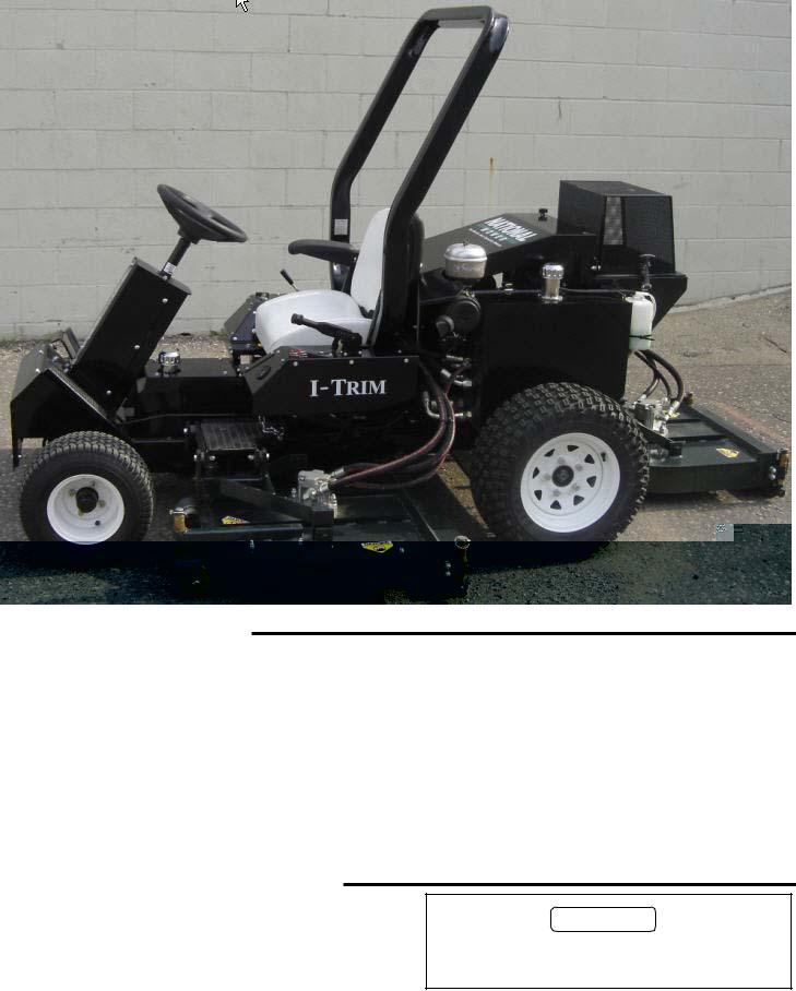
I-TRIM
OWNER'S MANUAL
Includes Specifications, Assembly, Operation,
Maintenance & Parts Lists
NATIONAL MOWER CO. 700 Raymond Ave., P.O. Box 14299, St. Paul, Minnesota 55114-0299, U.S.A.
Phone (651) 646-4079 – Fax (651) 646-2887 www.nationalmower.com
MARCH 2006
2

TABLE OF CONTENTS
Table of contents ...................................................... |
3 |
Introduction ............................................................... |
4 |
Safe Operating Practices ...................................... |
4-6 |
Decal (Transfer) Identification ............................... |
7-9 |
Introduction and Receipt of Shipment ................... |
10 |
1— Specifications ................................................... |
11 |
2— Assembly Instructions ...................................... |
12 |
3—General Information .......................................... |
15 |
4—Controls ............................................................. |
16 |
5—Operation .......................................................... |
18 |
6—Adjustments ...................................................... |
20 |
7—Maintenance ....................................................... |
22 |
8—Storage ................................................................ |
28 |
9—Troubleshooting .................................................. |
29 |
Wiring Diagram......................................................... |
33 |
Maintenance Record................................................. |
34 |
10—Parts Ordering Information ............................... |
35 |
Screen box, guards, ROPS................... |
36-37 |
Deck Lift Arms and Pull Arms ............... |
38-39 |
Seat, Wheels, Engine, Radiator, tank |
340-41 |
Wheel Motors, Filters, Hyd Comp. ....... |
42-43 |
Pedal Assy, Hyd Pumps ....................... |
44-45 |
Front Axle, Fuel Tank, Frame ............... |
46-47 |
Engine and Radiator Assembly ................. |
48 |
Rear Mower Deck Assembly ...................... |
49 |
Right Mower Deck Assembly ..................... |
50 |
Left Mower Deck Assembly ....................... |
51 |
HydraulicsDeck Motors/Oil Cooler ..... |
52-53 |
Hydraulics - Wheel Motors/Steering ..... |
54-55 |
Electrical System Components................... |
56 |
Steering Cylinder........................................ |
57 |
Hydraulic Schematic - Steering/Drive....................... |
58 |
Hydraulic Schematic - Mower Drives/Deck Lift......... |
59 |
Warrenty................................................................... |
61 |
Appendix 1- Briggs & Stratton Operating Instructions
I-TRIM®
3
INTRODUCTION
Read this manual carefully to learn how to operate and maintain your product properly. The information in this manual can help you and others avoid injury and product damage. The operator is responsible for operating this product properly and safely.
This manual identifies potential hazards and has special safety messages that help you and avoid personal injury and even death. Danger, Warning, and Caution are signal words used to identify the level of hazard. Howerver, regardless of the hazard, be extremely careful.
Danger signals an extreme hazard that will cause series injury or death if you do not follow the recommended precautions.
Warning signals a hazard that may cause serious injury or death if you do not follow the recommended precautions.
Caution signals a hazard that may cause minor or moderate injury if you do not follow the recommended precautions.
This manual uses two other words to highlight information. Important call attention to special mechanical information and Note: emphasizes general information worthy of special attention.
SAFETY
This machine meets or exceeds ANSI B71.4-1999 specifications in effect at the time of production.
Improper use or maintenance by the operator or owner can result in injury. To reduce the potential for injury, comply with these safety instructions and always pay attention to the safety alert symbols: CAUTION, WARNING, and DANGER. Failure to comply with the instruction may result in personal injury or death.
Safe Operating Practices
The following instructions are from CEN standard EN 836:1997, ISO standard 5395: 1990, and ANSI B71.4-1999.
Training
•Read the Operator’s Manual and other training material carefully. Be familiar with the controls, safety signs, and the proper use of the equipment.
•Never allow children or people unfamiliar with these instructions to use or service the mower. Local regulations may restrict the age of the operator.
•Never mow while people, especially children, or pets are nearby.
•Do not carry passengers.
•Keep in mind that the operator or user is responsible for accidents or hazards occurring to other people or their property.
•All drivers and mechanics should seek and obtain professional and practical instruction. The owner is responsible for training the users. Such instruction should emphasize:
-the need for care and concentration when working with ride-on machines;
-the owner/user can prevent and is responsible for accidents or injuries occurring to himself or herself, other people, or property;
-control of a ride-on machine sliding on a slope will not be regained by the application of the brake or putting transmission into neutral. Some reasons for loss of control are: insufficient wheel grip, driving too fast, inadequate braking, using a machine that is unsuitable for a task, lack of awareness of the effect of ground conditions (especially slopes), and incorrect load distribution.
Preparation
•Evaluate the terrain to determine what accessories and attachments are needed to properly and safely perform the job. Only use accessories and attachments approved by the manufacturer.
•While mowing, always wear substantial footwear, long trousers, hard hat, safety glasses, and ear protection. Long hair, loose clothing, or jewelry may get tangled in moving parts. Do not operate the equipment when barefoot or wearing open sandals.
•Thoroughly inspect the area where the equipment is to be used and remove all objects which may be thrown by the machine.
•Check that operator’s presence controls, safety switches, and shields are attached and functioning properly. Do not operate unless they are functioning properly.
•Warning - Fuel is highly flammable. Take the following precautions:
-Store fuel in containers specifically designed for this purpose.
-Refuel outdoors only and do not smoke while refuelling.
-Add fuel before starting the engine. Never remove the cap of the fuel tank or add fuel while the engine is running or when the engine is hot.
-If fuel is spilled, do not attempt to start the engine but move the machine away from the area of spillage and avoid creating any source of ignition until fuel vapors have dissipated.
4

Operation
• Do not operate the engine in a confined space where dangerous carbon monoxide fumes can collect.
• Operate only in daylight or in good artificial light. Stay alert for holes in the terrain and other hidden hazards.
• Before attempting to start the engine, disengage all blade attachment clutches, shift into neutral, and engage the parking brake. Only start the engine from the operator’s position. Use seat belts if provided.
• Never operate with the discharge deflector raised, removed, or altered, unless using a grass catcher.
• Remember there is no such thing as a safe slope. Travel on grass slopes requires particular care. To guard against overturning:
- do not stop or start suddenly when going up or downhill. - machine speeds should be kept low on slopes and during tight turns.
- stay alert for humps and hollows and other hidden hazards.
- never mow across the face of the slope, unless the mower is designed for this purpose.
• Watch out for traffic when crossing or near roadways. Slow down and use caution when making turns and crossing roads and sidewalks. Stop the blade rotation before crossing surfaces other than grass. Stop reels or deck blades if not mowing.
• When using any attachments, never direct discharge of material toward bystanders or allow anyone near the machine while in operation.
• Never operate the machine with damaged guards, shields, or without safety protective devices in place. Be sure all interlocks are attached, adjusted properly, and functioning properly.
• Do not change the engine governor settings or overspeed the engine. Operating the engine at excessive speed may increase the hazard of personal injury.
• Disengage drive to attachements when transporting or not in use.
• Before leaving the operator’s position: - stop on level ground;
- disengage the power take-off and blade rotation and lower the attachments;
- Change into neutral and set the parking brake; - stop the engine and remove the key.
•Keep hands and feet away from the cutting units.
I-TRIM®
•Stop the engine and disengage drive to attachment
-before refuelling;
-before removing the grass catchers;
-before making height adjustment unless adjustment can be made from the operator’s position.
-before clearing blockages;
-before checking, cleaning or working on the mower;
-after striking a foreign opject or if an abnormal vibration occurs. Inspect the mower for damage and make repairs before restarting and operating the equipment.
•Reduce the throttle setting before stopping engine and, if the engine is provided with a shut-off valve, turn the fuel off at the conclusion of mowing.
•Keep hands and feet away from cutting units.
•Look behind and down before backing up to be sure of a clear path.
•Do not operate the mower under the influence of alcohol or drugs.
•Use care when loading or unloading the machine into a trailer or truck.
•Use care when approaching blind corners, shrubs, trees, or other objects that may obscure vision.
Maintenance and Storage
•Keep all nuts, bolts and screws tight to be sure the equipment is in safe working condition. Replace all worn or damaged decals.
•Never store the equipment with fuel in the tank inside a building where fumes may reach an open flame or spark.
•Allow the engine to cool before storing in any enclosure.
•To reduct the fire hazard, keep the engine, silencer, battery compartment and fuel storage area free of grass, leaves, or excessive grease.
•Park machine on level ground. Never allow untrained personnel to service machine.
•Check the grass catcher frequently for wear or deterioration.
•Keep all parts in good working condition and all hardware and hydraulic fittings tightened.
•If the fuel tank has to be drained, do this outdoors.
•Shut off fuel while storing or transporting. Do not store fuel near flames. 5

•Be careful during adjustment of the machine to prevent entrapment of the fingers between moving blades and fixed parts of the machine Use care when checking blades. Wrap the blade(s) or wear gloves, and use caution when servicing them. Only replace blades. Never straighten or weld them.
•On multi-reel or blade machines, take care as rotating one blade can cause other blades to rotate.
•Disengage drives, lower the cutting units, set parking brake and stop engine. Wait for all movement to stop before adjusting, cleaning or repairing.
•Clean grass and debris from cutting units, drives, mufflers, and engine to help prevent fires. Clean up oil or fuel spillage.
•Use jack stands to support components when required.
•Carefully release pressure from components with stored energy.
•Disconnect battery before making any repairs. Disconnect the negative terminal first and the positive last. Reconnect positive first and negative last.
•Keep hands and feet away from moving parts. If possible, do not make adjustments with the engine running.
•Charge batteries in an open well ventilated area, away from spark and flames. Unplug charger before connecting or disconnecting from battery. Wear protective clothing and use insulated tools.
Other Riding Mower Safety Instructions
•Always follow all safety instructions to avoid serious injury or death. This product is capable of amputating hands and feet and throwing objects.
•Know how to stop the engine quickly.
•Wearing safety shoes and long pants is advisable and required by some local ordinances and insurance regulations.
•The operator must be skilled and trained in how to drive on hillsides. Failure to use caution on slopes or hills may cause loss of control and cause the vehicle to tip or roll, possible resulting in personal injury or death.
• Check the safety interlock switches daily for proper operation. If a switch should fail, replace the switch before operating the machine.
•Using the machine demands attention. To prevent loss of control:
-Do not drive close to sand traps, ditches, creeks, or other hazards.
-Reduce speed when making sharp turns. Avoid sudden stops and starts.
-When near or crossing roads, always yield the right-of- way.
-Reduce foward pedal movement when going downhill to keep forward speed slow and to maintain control of the machine.
•Do not touch the engine, muffler, hydraulic components, or exhaust pipe while the engine is running or soon after it has stopped because these areas could be hot enough to cause burns.
•Make sure all hydraulic line connectors are tight and all hydraulic hoses and lines are in good condition before applying pressure to the system.
•Keep your body and hands away from pin hole leaks or nozzles that eject hydraulic fluid under high pressure. Use paper or cardboard, not your hands, to search for leaks. Hydraulic fluid escaping under pressure can have sufficient force to penetrate the skin and cause serious injury.
•Before disconnecting or performing any work on the hydraulic sytem, all pressure in the system must be relieved by stopping the engine and lowering the cutting units and attachments to the ground.
IMPORTANT
CALIFORNIA Proposition 65 Warning - Diesel engine exhaust and some of its constituents are known to the State of California to cause cancer, birth defects, and other reproductive harm.
WARNING– California, USA residents are required by law (CA PRC 4442 & CA H & SC 13005) to equip their engines with spark arresters when operating in flammable vegitation. Arresters must be obtained from your engine dealer and are not available from National Mower Company.
6

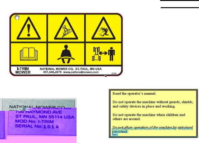
DECAL IDENTIFICATION
I-TRIM®
National has provided decals in many locations throughout the machine to aid the operator in identifying, controlling and operating the I-Trim safely and correctly. It is important that all decals are clean and visable at all times. Replace decals that are damaged, missing or accidently painted over.
A
B
D
 E C
E C
7

F
G
I
H  J
J
8
I-TRIM®
K
L M
|
|
NAMES AND LOCATIONS |
||
|
|
|
|
|
Item |
Part No. |
Description / Location |
||
|
|
|
|
|
A |
07792 |
I-Trim Model / Left and Right sides of operator panels |
||
B |
07794 |
Natinal Logo / Top of rear hood |
||
C |
07793 |
National Name / Front of steering column |
||
|
|
|
|
|
D |
07797 |
Diesel Fuel / Top of Fuel Tank |
||
E |
07796 |
Hydraulic Fluid / Top of hydraulic tank |
||
F |
07778 |
Warning light identification / Left side panel |
|
|
G |
07779 |
Key Switch and deck rotation switch / Right side panel |
||
H |
07777 |
Engine Speed / Left side panel |
||
I |
07411 |
Danger / Top of rear and wing mower decks |
||
|
|
|
||
J |
07780 |
Deck lift / Top of right operator panel |
|
|
K |
07795 |
Warning Decal / Top of steering column |
||
L |
|
I-Trim Serial Number / Right side of steering column |
||
M |
08092 |
Instruction DecalANSI / steering column |
||
|
|
|
|
|
|
|
|
|
|
9
INTRODUCTION
This manual has been prepared by National Mower Company as an aid to users for set up, operation and servicing and ordering replacement parts. Additional information will gladly be furnished by calling or writing the company.
Please furnish us with the Model number, serial number and date of purchase when contacting us about your machine.
Designations of right, left, front and rear are used in the position of the operator sitting in the seat.
Metric equivalents are provided wherever possible for users outside of the United States.
RECEIPT OF SHIPMENT
Carefully inspect your machine and crates for damage that could have occured during shipment. If damages or shortages are noted, have the transportation company’s representative note this on the bill of lading.
IMPORTANT
Claims for shipping damages must be noted by the consignee at the point of designation and filed with the transportation company.
10
1—SPECIFICATIONS
1.1—ENGINE SPECIFICATIONS
TYPE: |
3 cylinder turbocharged Diesel |
ENGINE MODEL: Briggs & Stratton |
|
|
954 DT |
HORSEPOWER: |
34 hp |
COOLING: |
Water cooled |
1.2—TRANSMISSION |
|
TRACTION DRIVE: Oilgear variable |
|
|
Displacement |
|
Hydrostatic pump |
WHEEL DRIVE |
Char Lynn hydraulic motors |
MOTORS: |
with disc-parking brakes |
1.3—STEERING
Eaton Power
Steering Control Unit
I-TRIM®
BATTERY TYPE: Exide Model 60 Premium
Type 78-60
12 V side post
7 3/16 (18 cm) height
6 ¾ (17 cm) width
10 1/4 (26 cm) length
1.5—CUTTING UNIT SPECIFICATIONS
CUTTING UNIT: |
(3) |
- 26” (.66m) wide decks |
BLADES: |
(2) |
Right hand 26” (.66 m) wide blades |
|
(1) |
Left hand 26” (.66m) wide blade |
DECK MOTORS:(2) |
CW Hydraulic motors (Right/Rear) |
|
|
(1) |
CCW Hydraulic motor (Left) |
Rotation direction as viewed from top of deck
WIDTH OF CUT: 70” (1.778m)
HEIGHT OF CUT: 1.5” to 4” adjustment (38.1mm to 101.62mm)
1.6—LUBRICANTS
ENGINE OIL: Refer to enclosed Engine Manual HYDRAULIC OIL: ISO 68 hydraulic grade oil.
1.4—MOWER SPECIFICATIONS
FUEL TANK: |
10 Gallons (38 liters) |
OIL TANK: |
12 Gallons (45 liters) Approx. |
TIRES: |
Front: 16 x 6.50 - 8 (28 psi max) |
|
Rear: 23 x 10.50 x 12 (20 psi max) |
FRAME: |
Welded steel construction |
MOWING SPEED: |
0 - 7 MPH (0 - 11.3 km) |
CONTROLS: |
Foot operated traction pedal for forward |
|
and reverse, hand operated throttle |
|
conttrol, electric valve for cutting units, |
|
and hand operated parking brake. |
1.7—OTHER
ROPS: |
Roll over protective structure |
|
meets SAE J 1194 standards |
11
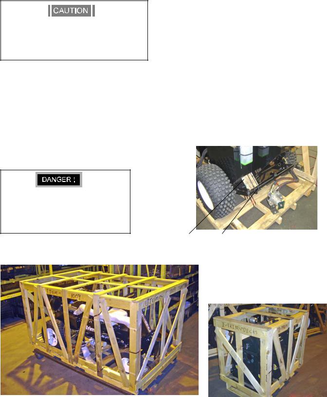
2—ASSEMBLY INSTRUCTIONS
2.1—TRACTOR ASSEMBLY
Handle banding material with caution. Use heavy leather gloves. Banding is sharp!
The side and rear lift arms are spring-loaded up. Take care when handeling.
1.Remove crating top, front and sides from the tractor crate. Cut banding from Roll-Over Protective Structure (ROPS) Fig A.
2.Cut banding from around tractor frame to crate base.
3.Unbolt rear deck motor from crate base and temporarily strap to rear lift arm. Leave wood spacer in place on rear lift arm to prevent damage.
3. Release parking brake and push or drive tractor off the crate. See operating instructions. Do not engage deck motors until tractor is fully assembled with decks. Reengage parking brake.
Use jack stands under tractor whenever elevated off the tires.
Do not engage deck motors untill tractor is fully assembled with decks.
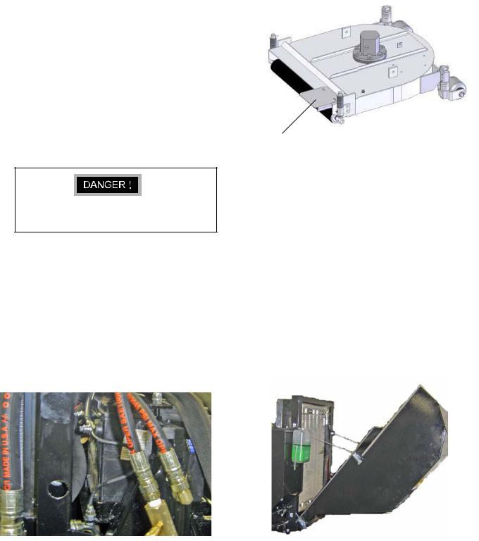
2.2—REAR DECK ASSEMBLY
1.Remove crating top, front and sides from deck crate. Unscrew blades from crate.
2.Remove rear deck from crate and position behind
tractor as shown in Figure C. Remove roll pin and washer from attachment shaft.
3.Insert a 1/2” rod into lift arm (Fig B) to lower and line-up the lift arm with the deck bushing. Insert shaft and secure with washer and roll pin. Remove wood spacer.
2.3—LEFT/RIGHT DECK ASSEMBLY
1.Remove left and right decks from crate and position near tractor as shown in Figure D. Remove attachment bolts.
2.Hold down and line-up lift arms with decks. Attach with supplied bolts and washers. Install lift chains.
Wood Spacer Insert rod |
FIGURE B |
|
12 |
FIGURE A |
|

2.4—DECK MOTORS AND BLADES
The I-Trim is available with standard or mulching blades. The Rear/Right decks require a RH blade and the left deck uses a LH blade.
NOTE
MULCHING BLADES
Rear/Right -P/N 306245 (stamped 306245)
Left -P/N 306311 (stamped 306311)
STRAIGHT BLADES
Rear/Right - P/N 306368 (stamped 4607) Left - P/N 306367 (stamped 6406)
Motor rotation direction is stamped on the flange of each deck motor. Rotation is clockwise (from above) on right and rear decks and counterclockwise on left deck.
NEVER START TRACTOR WITH DECKS ROTATED
1.Rotate decks vertical as shown in Fig E. Install deck motors with hoses rotated as shown in Fig C and D using supplied botts and nyloc nuts. Note: install ring spacer between motor and deck.
2.Install lift chains on rear deck with supplied bolts. Note: The rear deck has a anti-flip chain with quick-release connector link to allow easy removal for HOC adjustments.
I-TRIM®
2.5—ROPS
1. Install roll-over protective structure with supplied bolts and nuts as shown on Fig E. ROPS can be installed with seat in forward position. Lower ROPS over seat and insert LH side into position. Slide ROPS to RH side and spread it slightly to clear brackets. Install with supplied fasteners.
.
HEX BOLT ½-20 X 1½ GR 5
(4)
WASHER ½ SAE
(8)
NUT, NYLOCK ½-20
(4)
ROPS attachment points
Make sure anti-flip chain is installed on rear deck to prevent deck from rotating during operation.
Anti-flip chain
Attachment shaft and roll pin
FIGURE E
Side deck attachement bolts
FIGURE C |
FIGURE D |
13 |
|
|
2.6—ENGINE CRANKCASE
Crankcase oil has been installed at the factory. However it is recommended that the engine be checked for proper oil level before starting. Refer to separate engine manual included with each I-Trim Mower.
2.9—GUARD FOR DECK DISCHARGE
Each I-Trim Deck is supplied with a safety guard for the rear discharge area. These guards are supplied to prevent accidental insertion of a person’s foot and need to be installed as shown in Fig. G.
2.7—HYDRAULIC OIL
1. The hydraulic oil has been installed in the oil tank
(1, Fig. G) at the factory, however it is recommended that the oil level be check before operation.
2.Check oil level by removing pipe cap. The oil level should be at the bottom edge of the screen. If required, add a small amount of oil to the tank. and replace cap.
Recommended oil is ISO 68 Hydraulic grade oil.
2.8—BATTERY
Follow the battery manufacture’s instructions on safety, maintenance and installation procedures.
The I-Trim is shipped with a Exide Model 60 Premium, Type 78-60. Only replace with an equivalent battery.
1.Remove rear RH wheel to replace battery. Install battery with side mount terminals facing toward engine. See Fig F.
2.Place battery hold down strap over bolts and secure with flat washers and hex nuts. Do not over-tighten.
3.Connect the red ignition wire to the positive (+) terminal of the battery. Attach the engine ground wire and frame ground wire to the negative (–) terminal of the battery.
Guard |
FIGURE G |
2.10—SCREENBOX FOR RADIATOR
The I-Trim may be supplied with a pivoting rear screenbox as shown in Fig. H. The screenbox needs to be installed onto lower pivot brackets and secured with supplied cables and snap-latches.
|
FIGURE F |
FIGURE H |
14 |
|
|
|
|

3—GENERAL INFORMATION
NOTE
If adjustments are necessary see section 5.0 of the is manual for instructions.
3.1—ENGINE
Your machine is powered by a 3-cylinder Briggs and Stratton turbocharged diesel engine which uses diesel fuel. Engine speed is controlled by means of a throttle lever mounted on the dash panel.
A separate Engine Manual, prepared by the engine manufacturer is supplied. Study the manual carefully until you are familiar the maintenance, operation, adjustment and repair of your equipment. Proper attention to the engine manufacturers directions will assure maximum service life of the engine and highest operating efficiency.
3.2—TRACTION DRIVE TRAIN
Power from the engine is transmitted by direct drive to the variable displacement pump. The pump supplies hydraulic fluid to the hydraulic motors.
3.3—MOWER DECK DRIVE
Hydraulic power to the deck motors is actuated by electric switch mounted on the RH control panel. This switch actuates a solenoid valve in the deck manifold.
3.4—INTERLOCK SWITCHES
There are three safety switches on your I-Trim. They are a safety precaution, which will allow you to start your mower only when the traction pedal is in neutral, the deck motor control switch is in the disengaged position and the operator is seated on the tractor. If you are able to start your mower with the pedal or switch in any other position, adjustment of the switches may be required. After engine is started, it will continue to run if you leave the seat (as long as the deck switch is off and the pedal is in neutral).
Never operate the machine if the interlocks are not operating properly. Accidental startup could cause severe injury. Refer to Troubleshooting section (Sec 9).
I-TRIM®
15
4—CONTROLS
10
2
3
4
8
FIGURE J |
|
4.1—IGNITION SWITCH |
|
Insert key in switch (1, Fig.J) and turn clockwise to on |
Battery Charging |
|
|
position and wait until the glow plug light turns off. After light |
|
turns off, turn key clockwise as far as it will go to start engine, |
|
then release. The deck rotation control switch must be in the |
|
off position, the traction control pedal in the neutral position |
|
and a operator must be sitting on the seat before starting |
|
engine. |
|
Do not hold key in “ON” position more than 15 second at a |
|
time. |
|
Key should be removed when tractor is not in use to prevent |
|
unauthorized operation. |
|
Refer to section “5.2” for complete starting information. |
|
5 6
1
9
7
Oil Pressure LOW
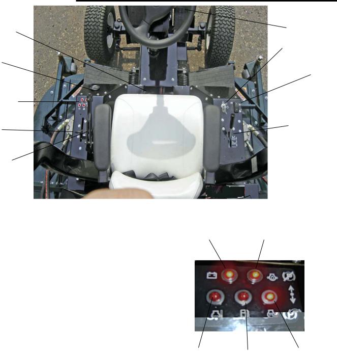
4.2—INDICATOR LAMPS
After engine is started, illumination of any indicator lamp will indicate a problem (3, Fig J). Stop engine and correct problem.
When Key is turned to “ON” the Battery Charging, Glow Plug ON, and the Oil Pressure indicator lamps should illuminate. After 5 seconds, the Glow Plug ON light should turn off (Fig K).
Water Temperature Water in Fuel Glow Plug ON
FIGURE K 4.3—HOUR METER
The hour meter (2,Fig. J) indicates the number of hours the tractor has been operated. It can be used to keep track of maintenance intervals and the amount of time required to perform various tasks. The hour meter operates whenever the ignition key is in the “on” position.
Your I-Trim Mower maybe equipped with a digital hour meter. This meter will display a signal after 5 hours and every 25 hours thereafter, recommending that you perform maintanncel and lubricate the mower. (see sec.7). The display will automaticly reset after 2 additional hours of run time.
16

4.4—THROTTLE LEVER
Push throttle lever (4, Fig. J) forward to increase engine speed, pull back to decrease the engine speed.
Position throttle at full throttle or slightly less for optimum power and deck speed during mowing.
4.5—TRACTION PEDAL
The traction pedal (5, Fig. J) operates the forward and the reverse direction and speed of the tractor.
Moving forward: push the forward or toe of the pedal down with the ball of your foot, to increase the forward speed.
Moving backward: push the heel of the pedal down with the heel of your foot, to increase the reverse speed.
When the traction pedal is released the machine will slow down and stop. The traction pedal must be in neutral position before mower will start.
4.6—SPEED CONTROL
The speed control (6, Fig. J) is meant to ease operator fatigue by holding the forward speed to a constant that is best suited for the present mowing conditions. The stop also prevents overloading of the pintle shaft.
Adjust the hex head bolt up or down and lock it with the lock nut to limit the pedal travel. Make sure the pintle shaft on the pump is not bottomed-out by watching the linkage deflection when pedel is all the way down.
4.7—DECK LIFT
The Deck Lift valve (7, Fig. J), will lift both wing decks and rear deck by pulling lever to rear. Pushing lever to front will lower all deck to the ground. Always lower decks for mowing and storage.
Do not stand on mowers when in lifted position.
4.8—PARKING BRAKE
A convenient parking brake (8, Fig. J) is located just to the left side of the operators seat.
Pulling back and over center will engage the parking brake and moving it forward, as shown, will release it. See section 6.1 for adjustments.
IMPORTANT
Always make sure brake is released before moving forward and ensure that the brake is engaged when leaving the mower. Never try to stop the forward motion of the unit with the parking brake.
I-TRIM®
4.9—DECK DRIVE CONTROL
By toggling the deck drive control switch ON (9, Fig. J), an electric solenoid valve is activated which engages power to the deck motors.
Pushing the switch to the OFF position disengages the valve. This contrtol must be in the OFF position before mower will start.
4.10—SEAT POSITION LEVER
The position of the seat is adjusted forward or backward by actuating the seat lever (10, Fig. J).
Releasing the lever will lock the seat at its present position.
17

5—OPERATION
5.1—CHECK LIST
1.Fill the fuel tank with good quality, clean, diesel with a minimum of 40 octane. Fresh fuel prevents gum from forming in the fuel system. Fill tank to 1 inch (25 mm) below filler neck. Do not overfill.
2.Check oil in the engine crankcase. It should be filled to the full mark on the dipstick. Refer to Section 1.6 in this manual for recommend oil viscosity.
3.Check all lubrication points outlined in the “Section 7.14 Lubrication” section of this manual. Check linkage for traction pedal to the pump for wear or damage.
4.Check tires for proper inflation. Refer to section 1.4 of this manual.
5.Check oil level in hydraulic reservoir. Oil level should be level with the bottom of the screen when looking into the fill neck and when unit is sitting on a level surface.
6.Check decks for desired cutting height. To provide a satisfactory cut, it is essential for all decks be accurately adjusted to exactly the same height. See 6.9 in the Adjustments Section.
OPERATING SUGGESTIONS
Under no circumstances should the engine be started with the operator or bystander standing next to tractor or cutting units.
1.When starting the engine, the operator must be seated on the seat, deck control switch must be OFF and traction pedal must be in neutral (the center position).
2.The operator should practice mowing in an open clear area, to become thoroughly familiar with the operation of the tractor.
3.Never operate the mowers when they are in the up position because of the dangers of flying objects and exposed blades.
4.Plan your cutting pattern to avoid any unnecessary stops or sharp, frequent turns. Study the area to determine the best mowing procedure. Consider the height of the grass and the type of terrain (level, hilly, or rough). Each condition will require certain adjustments or precautions.
5.Before leaving the mower, always lower deck mowers so that when exiting the mower and stepping on the nonskid pads of the wing mowers, it will not put excessive strain on the lift mechanism.
18
6.Operate at speeds which allow you to have complete control of the tractor and allow you to stop the tractor or maneuver safely in case of an emergency. It is recommended that you adjust the Speed Control (6, Fig. J), to maintain a constant pedal postion/speed and reduce the operator fatigue.
7.To obtain maximum mower life, the operator must use discretion when mowing near gravel areas (roadway, parking areas, cart paths etc.) By operating too close to overlapping gravel areas, stones maybe picked up by the mower and ejected under the deck causing wear to the blades and damage from flying objects.
5.2— STARTING THE ENGINE
1.Sit in operators seat.
2.Place deck control switch in the “OFF” position (9, Fig J).
3.Place the traction pedal in “Neutral” position (5, Fig J).
4.Engage parking brake (8, Fig J).
5.Insert ignition key, turn clockwise to “run” position and wait until the glow plug ON light turns off. Turn key clockwise to “start” and release key when engine starts. Do not hold key in “start” position for more than 15 seconds or damage to the starter may result. If engine does not start within this time, release the key and wait for a few minutes before trying again.
5.3—DRIVING THE TRACTOR
1.Position throttle at full throttle or slightly less for optimum power and deck speed.
2.Release parking brake (8, Fig. J).
3.Moving forward: Push the toe of the traction pedal forward with the ball of your foot, to increase the forward speed .
4.Moving backward: Push the heel of the traction pedal in with the heel of your foot, to increase the reverse speed.
5.To return traction pedal to neutral, rock pedal with foot until pedal stops. The pedal will stay in neutral when you remove your foot.
To avoid possible loss of control and/or serious bodily injury, avoid abrupt chages in the tration pedal position. Reduce speed on slopes, rough terrain, and in sharp turns to prevent tipping or loss of control.

5.4—MOWING OPERATION
1.Check the turf area for debris that would cause
damage to the decks. Never operate the decks when they are in the UP position because of the danagers of flying objects and exposed blades.
2.When cutting large areas, the most satisfactory method is to first cut the outer area and then mow clockwise toward the center. The next time you cut, it is advised that you mow in the opposite direction to prevent grass matting.
3.Cutting speeds are governed by conditions of turf, type of terrain and opstacles to be encountered. Operate tractor at slow speeds when turning.
5.5—MOWING
1. Stop tractor, by releasing the traction pedal, then slowly lower the mower units (5, Fig.J) and (7, Fig. J).
Dropping mower decks abruptly could damage them. Always check for bystanders before lowering.
2.Engage deck control switch (9, Fig. J) to the ON position.
3.Depress traction pedal to the desired speed (sections
4.6and 4.7). Deck speed is constant and ground speed is variable with the traction pedal. Do not try to regulate ground speed with engine throttle (section 4.5).
5.6—HILLSIDE OPERATION
The I-Trim has been designed for good traction and stability under normal mowing conditions. However, caution must still be used during slope operation, especially when the grass is wet. Wet grass limits traction and steering control.
In order to minimize the possibility of tipping, the least dangerous method of operating on hills and terraces is to travel horizontally to the hill. It is also advisable to avoid any unnecessary turns while operating on hills. Use extreme caution and travel at reduce speeds.
I-TRIM®
1.When operating on hillsides or slopes, maintain full engine speed, but let up on the traction pedal as power requirements increase. This will maintain the performance necessary.
2.It is best to mow along the side of the hill, starting at the bottom and working upwards. This allows the machine to negotiate the slope without mowing in a downhill direction.
3.It is essential for the correct tire pressure to be established for maximum traction and hillside holding.
5.7—PUSHING OR TOWING
INSTRUCTIONS
The I-Trim should not be pushed or towed with the engine not running. If needed, the I-Trim can be pushed or towed at slow speeds for very short distances without starting the engine.
Do not exceed 2 mph while pushing or towing.
A screw-adjustable valve is located on the underside of the pump for towing. Note: Do not exceed 2 mph while pushing or towing. Loosen the lock nut and turn the screw CCW to release pressure. After towing, tighten the screw by turning CW and lock into place with the locknut.
19
 Loading...