


Inverter Generator
Operator’s Manual
|
|
|
|
|
|
Reproduction |
|
|
|
|
|
|
|
Not |
for |
|
|
|
|
|
|
|
|
|
|
|
|
|
|
|
|
|
|
|
|
|
|
|
|
|
|
|
|
|
|
|
|
|
|
|
|
|
|
|
|
|
|
|
|
|
|
|
|
|
|
|
|
|
|
|
|
|
|
|
|
|
|
|
|
|
|
|
|
|
|
|
|
This generator is rated in accordance with CSA (Canadian Standards
Association) standard C22.2 No. 100-04 (motors and generators).
BRIGGS & STRATTON POWER PRODUCTS GROUP, LLC
MILWAUKEE, WISCONSIN, U.S.A.
Manual No. 311157GS Revision C

Thank you for purchasing this quality-built Briggs & Stratton® generator. We are pleased that you’ve placed your confidence in the Briggs & Stratton brand. When operated and maintained according to the instructions in this manual, your Briggs & Stratton generator will provide many years of dependable service.
This manual contains safety information to make you aware of the hazards and risks associated with generators and how to avoid them. This generator is designed and intended only for supplying electrical power for operating compatible electrical lighting, appliances, tools and motor loads, and is not intended for any other purpose. It is important that you read and understand these instructions thoroughly before attempting to start or operate this equipment. Save these original instructions for future reference.
This generator requires final assembly before use. Refer to the Assembly section of this manual for instructions on final assembly procedures. Follow the instructions completely.
Where to Find Us
You never have to look far to find Briggs & Stratton support and service for your generator. Consult your Yellow Pages. There are over 30,000 Briggs & Stratton authorized service dealers worldwide who provide quality service. You can also contact Briggs & Stratton Customer Service by phone at (800) 743-4115, or on the Internet at BRIGGSandSTRATTON.COM.
Generator
Model Number
Revision
Serial Number
Date Purchased
Reproduction |
|
Not |
for |
|
|
Copyright © 2011. Briggs & Stratton Power Products Group, LLC
Milwaukee, WI, USA. All rights reserved.
BRIGGS & STRATTON POWER PRODUCTS is a registered
trademark of Briggs & Stratton Corporation
Milwaukee, WI, USA
2 |
BRIGGSandSTRATTON.COM |

Table of Contents
Operator Safety . . . . . . . . . . . . . . . . . . . . . . . . . . . . . . . . . 4
Equipment Description. . . . . . . . . . . . . . . . . . . . . . . . . . . . . . . . . . . . . . . . . 4
Important Safety Information. . . . . . . . . . . . . . . . . . . . . . . . . . . . . . . . . . . . 4
Assembly . . . . . . . . . . . . . . . . . . . . . . . . . . . . . . . . . . . . . 7
Unpack Generator . . . . . . . . . . . . . . . . . . . . . . . . . . . . . . . . . . . . . . . . . . . . 7
Add Engine Oil . . . . . . . . . . . . . . . . . . . . . . . . . . . . . . . . . . . . . . . . . . . . . . . 7
Add Fuel. . . . . . . . . . . . . . . . . . . . . . . . . . . . . . . . . . . . . . . . . . . . . . . . . . . . 7
Grounding Fastener . . . . . . . . . . . . . . . . . . . . . . . . . . . . . . . . . . . . . . . . . . . 8
Generator Location . . . . . . . . . . . . . . . . . . . . . . . . . . . . . . . . . . . . . . . . . . . 8
Features and Controls . . . . . . . . . . . . . . . . . . . . . . . . . . . . . 9
Cord Sets and Receptacles . . . . . . . . . . . . . . . . . . . . . . . . . . . . . . . . . . . . 10
Operation . . . |
. . |
. . . . . . . . |
. . . . . . . . . . . . . . . . . . . . . . . |
11 |
Starting the Engine . . . . . . . . . . |
. . . . . . . . . . . . . . . . . . . . . . . . . . . . . . . . |
11 |
||
Connecting Electrical Loads. . . . |
. . . . . . . . . . . . . . . . . . . . . . . . . . . . . . . . |
11 |
||
Stopping the Engine. . . . . . . . . . |
. . . . . . . . . . . . . . . . . . . . . . . . . . . . . . . . |
12 |
||
|
Reproduction |
|
||
POWERSMART Mode . . . . . . . . |
. . . . . . . . . . . . . . . . . . . . . . . . . . . . . . . . |
12 |
||
Charging a Battery . . . . . . . . . . . |
. . . . . . . . . . . . . . . . . . . . . . . . . . . . . . . . |
12 |
||
Don’t Overload Generator . . . . . |
. . . . . . . . . . . . . . . . . . . . . . . . . . . . . . . . |
13 |
||
Maintenance . . |
. |
. . . . . . . . |
. . . . . . . . . . . . . . . . . . . . . . . |
14 |
Maintenance Schedule . . . . . . . . |
. . . . . . . . . . . . . . . . . . . . . . . . . . . . . . . . |
14 |
||
Warranties. . . . |
. |
Not. . . . . . . . |
. . . . . . . . . . . . . . . . . . . . . . . |
21 |
Generator Maintenance . . . . . . . |
. . . . . . . . . . . . . . . . . . . . . . . . . . . . . . . . |
14 |
||
Engine Maintenance. . . . . . . . . . |
. .for. . . . . . . . . . . . . . . . . . . . . . . . . . . . . . |
15 |
||
Storage . . . . . . |
. |
. . . . . . . . . . . . |
. . . . . . . . . . . . . . . . . . . . . . . . . . . . . . . . |
18 |
Troubleshooting . |
. . . . . . . . |
. . . . . . . . . . . . . . . . . . . . . . . |
19 |
|
Wiring Diagram . |
. . . . . . . . . . . . |
. . . . . . . . . . . . . . . . . . . . . . . . . . . . . . . . |
20 |
|
Emissions Control System Wa |
anty . . . . . . . . . . . . . . . . . . . . . . . . . . . . . |
21 |
||
Generator Owner Warranty . . . . |
. . . . . . . . . . . . . . . . . . . . . . . . . . . . . . . . |
23 |
||
Specifications . |
. |
. . . . . . . . |
. . . . . . . . . . . . . . . . . . . . . . . |
24 |
Product Specifications . . . . . . . . |
. . . . . . . . . . . . . . . . . . . . . . . . . . . . . . . . |
24 |
||
Common Service Parts . . . . . . . |
. . . . . . . . . . . . . . . . . . . . . . . . . . . . . . . . |
24 |
||
3

Operator Safety
Equipment Description
Read this manual carefully and become familiar with your generator. Know its applications, its limitations and any hazards involved.
The generator is an engine–driven, revolving field, alternating and direct current (AC & DC) generator. It was designed to supply electrical power for operating compatible electrical lighting, appliances, tools and motor loads. The generator’s revolving field is driven at about 4,500 rpm (with POWERSMART mode switch off) by a single-cylinder engine.
Safety Symbols and Meanings
Toxic Fumes |
Kickback |
Electrical Shock |
|||||
|
|
|
|
|
|
|
|
|
|
|
|
|
|
|
|
|
|
|
|
|
|
|
|
|
|
|
|
|
|
|
|
Fire |
Explosion |
Operator’s Manual |
NOTICE Exceeding generators wattage/amperage capacity |
|
Moving Parts |
Flying Objects |
Hot Surface |
|||
can damage generator and/or electrical devices connected |
|
||||||
|
|
|
|
|
|
||
to it. |
|
|
|
|
|
|
|
• DO NOT exceed the generator’s wattage/amperage capacity. See |
|
|
|
|
|
|
|
Don’t Overload Generator in the Operation section. |
|
|
|
|
|
|
|
|
|
|
Explosive Pressure |
|
Chemical Burn |
||
|
Reproduction |
|
|
||||
Every effort has been made to ensure that the information in |
|
The safety alert symbol i |
dicates a potential personal |
||||
this manual is both accurate and current. However, the |
|
||||||
manufacturer reserves the right to change, alter or otherwise |
inju y hazard. A signal w rd (DANGER, WARNING, or |
||||||
improve the generator and this documentation at any time |
|
CAUTION) is used w |
h the alert symbol to designate a |
||||
without prior notice. |
|
|
degree or level f hazard seriousness. A safety symbol may |
||||
The Emission Control System for this generator is warran ed |
be used to represent |
he type of hazard. The signal word |
|||||
for standards set by the Environmental Protecti n Agency |
forNOTICE is sed to address practices not related to personal |
||||||
and the California Air Resources Board. |
|
|
inj ry. |
|
|
|
|
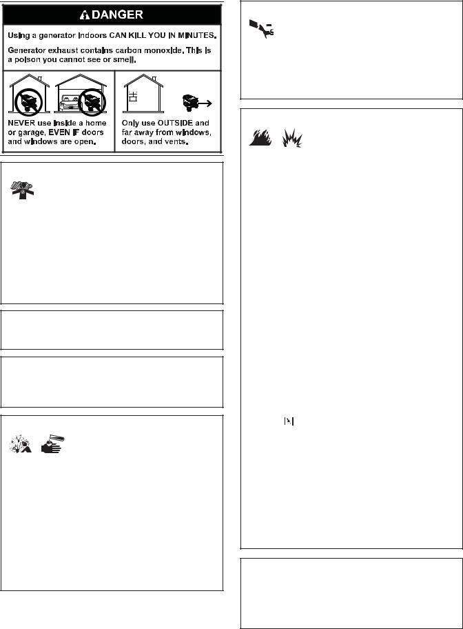
Important Safety Information |
DANGER indicates a hazard which, if not avoided, will |
|
result in death or serious injury. |
||
The manufacturer cannot possibly anticipate every possible |
||
WARNING indicates a hazard which, if not avoided, |
||
circumstance that might involve a hazard.NotThe warnings in |
||
c uld result in death or serious injury. |
||
this manual, and the tags and decals affixed to the unit a e, |
||
CAUTION indicates a hazard which, if not avoided, could |
||
therefore, not all-inclusive. If you use a procedure, wo k |
||
result in minor or moderate injury. |
||
method or operating technique that the manufactur r do s |
||
NOTICE address practices not related to personal injury. |
||
not specifically recommend, you must satisfy yours lf that it |
||
|
||
is safe for you and others. You must also make sure that the |
|
|
procedure, work method or operating technique that you |
|
|
choose does not render the generator unsafe. |
|
4 |
BRIGGSandSTRATTON.COM |
|
|
|
WARNING Starter cord kickback (rapid retraction) will |
||
|
|
|
pull hand and arm toward engine faster than you |
||
|
|
|
can let go which could cause broken bones, |
||
|
|
|
fractures, bruises, or sprains resulting in serious |
||
|
|
injury. |
|
||
|
|
• When starting engine, pull cord slowly until resistance is felt |
|||
|
|
|
and then pull rapidly to avoid kickback. |
||
|
|
• NEVER start or stop engine with electrical devices plugged in |
|||
|
|
|
and turned on. |
|
|
|
|
|
WARNING Fuel and its vapors are extremely |
||
|
|
|
|
flammable and explosive which could |
|
|
|
|
|
cause burns, fire or explosion resulting |
|
|
|
damage. |
in death, serious injury and/or property |
||
|
|
|
|||
WARNING Running engine gives off carbon |
WHEN ADDING OR DRAINING FUEL |
||||
monoxide, an odorless, colorless, poison gas. |
• Turn generator engine OFF and let it cool at least 2 minutes |
||||
Breathing carbon monoxide could result in death, |
|
before removing fuel cap. Loosen cap slowly to relieve pressure |
|||
serious injury, headache, fatigue, dizziness, |
|
in tank. |
|
||
vomiting, confusion, seizures, nausea or fainting. |
• Fill or drain fuel tank outdoors. |
||||
• Operate this product ONLY outdoors. |
|
||||
|
• DO NOT overfill tank. Allow space for fuel expansion. |
||||
• Install a battery operated carbon monoxide alarm near the |
|||||
• |
If fuel spills, wait u til it evaporates before starting engine. |
||||
bedrooms. |
|
||||
|
• Keep fuel away from sparks, open flames, pilot lights, heat, and |
||||
• Keep exhaust gas from entering a confined area through |
|||||
|
ther ignition s |
urces. |
|||
windows, doors, ventilation intakes, or other openings. |
|
||||
• DO NOT operate this product inside any building, carport, |
• |
Check fuel l nes, |
ank, cap and fittings frequently for cracks or |
||
porch, mobile equipment, marine applications, or enclosure, |
|
leaks. Replace f necessary. |
|||
even if windows and doors are open. |
|
• |
DO NOT light a igarette or smoke. |
||
WARNING The engine exhaust from this pr duct |
forWHEN STARTING EQUIPMENT |
||||
• |
Ens re spark plug, muffler, fuel cap, and air cleaner are in |
||||
contains chemicals known to the State of Calif rnia to |
|||||
|
place. |
|
|||
cause cancer, birth defects, or other reproductive harm. |
• DO NOT crank engine with spark plug removed. |
||||
|
|
||||
WARNING Certain components in this product and |
WHEN OPERATING EQUIPMENT |
||||
• DO NOT operate this product inside any building, carport, |
|||||
|
Not |
||||
|
|
porch, mobile equipment, marine applications, or enclosure. |
|||
related accessories contain chemicals known to the State |
|
||||
of California to cause cancer, birth defects or other |
• DO NOT tip engine or equipment at angle which causes fuel to |
||||
reproductive harm. Wash hands after handling. |
|||||
|
spill. |
|
|||
|
|
• DO NOT stop engine by moving choke control to “Choke” |
|||
WARNING Storage batteries give off explosive |
|
position ( ). |
|
||
hydrogen gas during recharging. |
WHEN TRANSPORTING, MOVING OR REPAIRING EQUIPMENT |
||||
Hydrogen gas stays near battery for a |
• Transport/move/repair with fuel tank EMPTY or with fuel shutoff |
||||
long time after batteryReproductionhas been |
|||||
charged. Slightest spark could ignite hydrogen causing |
|
valve OFF. |
|
||
• DO NOT tip engine or equipment at angle which causes fuel to |
|||||
explosion resulting in death, serious injury and/or |
|||||
|
spill. |
|
|||
property damage. |
|
|
|
||
|
• Disconnect spark plug wire. |
||||
Battery electrolyte fluid contains acid and is extremely |
|||||
caustic. Contact with battery fluid could cause chemical |
WHEN STORING FUEL OR EQUIPMENT WITH FUEL IN TANK |
||||
burns resulting in serious injury and/or property damage. |
• Store away from furnaces, stoves, water heaters, clothes |
||||
• DO NOT allow any open flame, spark, heat, or lit cigarette |
|
dryers, or other appliances that have pilot light or other ignition |
|||
during and for several minutes after charging a battery. |
|
source because they could ignite fuel vapors. |
|||
|
|
|
|||
•Wear protective goggles, rubber apron, and rubber gloves.
•DO NOT continue to charge a battery that becomes hot or is
fully charged.
• DO NOT leave battery unattended.
5
|
WARNING Generator voltage could cause electrical |
|
|
WARNING Unintentional sparking could cause fire or |
||||||
|
|
shock or burn resulting in death or serious |
|
|
|
|
|
electric shock resulting in death or |
||
|
|
|
|
|
|
|
||||
|
|
injury. |
|
|
|
|
|
serious injury. |
||
• DO NOT connect generator to a building’s electrical system. |
|
|
|
|
|
|
||||
|
WHEN ADJUSTING OR MAKING REPAIRS TO YOUR GENERATOR |
|||||||||
• DO NOT touch bare wires or receptacles. |
|
• Disconnect the spark plug wire from the spark plug and place |
||||||||
• DO NOT use generator with electrical cords which are worn, |
|
|
the wire where it cannot contact spark plug. |
|||||||
|
frayed, bare or otherwise damaged. |
|
WHEN TESTING FOR ENGINE SPARK |
|||||||
• DO NOT operate generator in the rain or wet weather. |
|
• Use approved spark plug tester. |
||||||||
• DO NOT handle generator or electrical cords while standing in |
|
• DO NOT check for spark with spark plug removed. |
||||||||
|
water, while barefoot, or while hands or feet are wet. |
|
|
|
|
|
|
|||
|
|
|
|
|
|
|
||||
• DO NOT allow unqualified persons or children to operate or |
|
|
|
|
|
|
||||
|
|
CAUTION Excessively high operating speeds could |
||||||||
|
service generator. |
|
|
|||||||
|
|
|
|
|
|
result in minor injury and/or generator damage. |
||||
|
|
|
|
|
||||||
|
|
|
|
|
|
Excessively low speeds impose a heavy load. |
||||
|
WARNING Exhaust heat/gases could ignite |
|||||||||
|
|
• DO NOT tamper with governor spring, links or other parts to |
||||||||
|
|
|
|
combustibles, structures or damage fuel |
|
|||||
|
|
|
|
|
|
increase engine speed. Generator supplies correct rated |
||||
|
|
|
|
tank causing a fire, resulting in death, |
|
|
||||
|
|
|
|
|
|
frequency and voltage when running at governed speed. |
||||
|
|
|
|
serious injury and/or property damage. |
|
• DO NOT modify generator in any way. |
||||
|
|
|
|
|
||||||
|
|
|
||||||||
Contact with muffler area could cause burns resulting in |
|
|||||||||
|
|
|
|
|
|
|||||
serious injury. |
|
|
|
|
|
|
||||
• DO NOT touch hot parts and AVOID hot exhaust gases. |
|
|
|
|
|
||||
• Allow equipment to cool before touching. |
|
NOTICE |
Exceeding generators wattage/amperage capacity |
||||||
• Keep at least 5 feet (152 cm) of clearance on all sides of |
|
||||||||
|
could damage generator a |
d/or electrical devices connected |
|||||||
|
|
generator including overhead. |
|
|
to it. |
|
|
|
|
• It is a violation of California Public Resource Code, Section |
|
|
|
|
|||||
|
• DO NOT exceed the ge |
erat |
r’s wattage/amperage capacity. See |
||||||
|
|
4442, to use or operate the engine on any forest-covered, |
|
||||||
|
|
|
D n’t Overload Generat |
r in the Operation section. |
|||||
|
|
brush-covered, or grass-covered land unless the exhaust |
|
||||||
|
|
|
• Start genera or and let engine stabilize before connecting |
||||||
|
|
system is equipped with a spark arrester, as defined in Sec ion |
|
||||||
|
|
4442, maintained in effective working order. Other sta es or |
|
electri al loads. |
|
|
|||
|
|
federal jurisdictions may have similar laws. |
for• Conne t ele tri al loads in OFF position, then turn ON for |
||||||
|
|
Contact the original equipment manufacturer, retailer, r dealer |
|
operation. |
|
|
|||
|
|
to obtain a spark arrester designed for the exhaust system |
|
• T rn electrical loads OFF and disconnect from generator before |
|||||
|
|
installed on this engine. |
|
|
stopping generator. |
|
|
||
• Replacement parts must be the same and installed in the same |
|
|
|
|
|
||||
|
|
position as the original parts. |
Not |
|
|
|
|
||
|
|
|
|
NOTICE |
Improper treatment of generator could damage it |
||||
|
|
|
|
|
|
||||
|
|
WARNING Starter and other rotating parts could |
|
||||||
|
|
|
and shorten its life. |
|
|
||||
|
|
|
entangle hands, hair, clothing, or acc ssori s |
|
|
|
|||
|
|
|
|
|
|
||||
|
|
|
|
• Use generator only for intended uses. |
|||||
|
|
|
resulting in serious injury. |
|
|
||||
|
|
|
|
|
• If you have questions about intended use, ask dealer or contact |
||||
|
|
|
|
|
|
||||
• |
NEVER operate generator without protective housing or cov rs. |
|
|||||||
|
local service center. |
|
|
||||||
• DO NOT wear loose clothing, jewelry or anything that could be |
|
• Operate generator only on level surfaces. |
|||||||
|
|
caught in the starter or other rotating parts. |
|
• DO NOT expose generator to excessive moisture, dust, dirt, or |
|||||
• |
Tie up long hair and remove jewelry. |
Reproductioncorrosive vapors. |
|||||||
|
|
|
|
|
|
|
|
|
|
• DO NOT insert any objects through cooling slots.
• If connected devices overheat, turn them off and disconnect them from generator.
• Shut off generator if:
-electrical output is lost;
-equipment sparks, smokes, or emits flames; -unit vibrates excessively.
6 |
BRIGGSandSTRATTON.COM |
Assembly |
|
|
|
|
NOTICE |
Improper treatment of generator could damage it |
|||
Your generator requires some assembly and is ready for use |
|
and shorten its life. |
|||||||
|
• DO NOT attempt to crank or start the engine before it has been |
||||||||
after it has been properly serviced with the recommended |
|
|
|
properly serviced with the recommended oil. This could result in |
|||||
fuel and oil. |
|
|
|
|
|
an engine failure. |
|||
If you have any problems with the assembly of your generator, |
|
|
5. |
Replace oil fill cap and fully tighten. |
|||||
please call the generator helpline at (800) 743-4115. If calling |
|
|
|
6. Replace the maintenance cover and hand tighten the |
|||||
for assistance, please have the model, revision, and serial |
|
|
|
||||||
|
|
|
|
two maintenance cover screws. |
|||||
number from the identification label available. See Generator |
|
|
Add Fuel |
||||||
Features and Controls for identification label location. |
|
|
|||||||
Unpack Generator |
|
|
|
|
Fuel must meet these requirements: |
||||
1. |
Set the carton on a rigid, flat surface. |
|
|
|
|
• |
Clean, fresh, unleaded gasoline. |
||
2. |
Remove everything from carton except generator. |
|
|
|
• |
A minimum of 87 octane/87 AKI (91 RON). For high |
|||
3. |
Open carton completely by cutting each corner from |
|
|
|
|
altitude use, see High Altitude. |
|||
|
top to bottom. |
|
|
|
|
|
• |
Gasoline with up to 10% ethanol (gasohol) or up to |
|
The generator is supplied with: |
|
|
|
|
|
|
15% MTBE (methyl tertiary butyl ether) is acceptable. |
||
|
|
|
|
NOTICE |
Avoid generator damage. |
||||
• |
Battery charge cables |
|
|
|
|
||||
• |
Operator’s manual |
|
|
|
|
Failure to follow Operator’s Manual for fuel |
|||
|
|
|
|
recommendations voids warranty. |
|||||
• |
Engine oil bottle |
|
|
|
|
||||
|
|
|
|
• |
DO NOT use unapproved gasoli e such as E85. |
||||
|
|
|
|
|
|
||||
Add Engine Oil |
|
|
|
|
• |
DO NOT mix oil in gasoli e. |
|||
|
|
|
|
• |
DO NOT modify engi e to run on alternate fuels. |
||||
1. Place generator on a level surface. |
|
|
|
||||||
|
|
|
|
|
|
|
|||
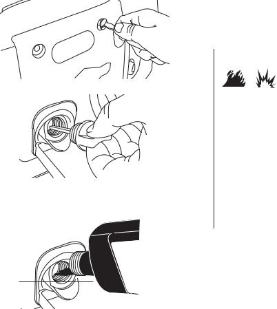
2. |
Loosen the two maintenance cover screws and remove |
|
To pr tect |
he fuel sys em fr m gum formation, mix in a fuel |
|||||
|
the side maintenance cover. |
|
|
|
|
stabilizer when add ng fuel. See Storage. All fuel is not the |
|||
|
|
|
|
|
|
same. If you experience starting or performance problems after |
|||
|
|
|
Not |
|
for |
|
|||
|
|
|
|
|
using f el, swit h to a different fuel provider or change brands. |
||||
|
|
|
|
|
This engine is certified to operate on gasoline. The emission |
||||
|
|
|
|
|
control system for this engine is EM (Engine Modifications). |
||||
|
|
|
|
|
|
|
|
||
|
|
|
|
|
|
|
WARNING Fuel and its vapors are extremely flammable |
||
|
|
|
|
|
|
|
|
and explosive which could cause burns, |
|
|
|
|
|
|
|
|
|
fire or explosion resulting in death, |
|
3. |
Clean area around oil fill and remove yellow oil fill cap. |
|
|
|
|
|
|||
|
|
|
|
|
serious injury and/or property damage. |
||||
|
|
Rep |
|
|
WHEN ADDING FUEL |
||||
|
|
|
|
• Turn generator engine OFF and let it cool at least 2 minutes |
|||||
|
|
|
|
before removing fuel cap. Loosen cap slowly to relieve pressure |
|||||
|
|
|
|
in tank. |
|
||||
|
|
|
|
• Fill fuel tank outdoors. |
|||||
|
|
|
|
• DO NOT overfill tank. Allow space for fuel expansion. |
|||||
|
|
roduction |
|||||||
|
|
|
|
|
|
|
• If fuel spills, wait until it evaporates before starting engine. |
||
|
|
|
|
|
|
|
• Keep fuel away from sparks, open flames, pilot lights, heat, and |
||
4. Using oil funnel (optional), slowly pour contents of |
|
|
|
other ignition sources. |
|||||
|
|
|
• Check fuel lines, tank, cap and fittings frequently for cracks or |
||||||
|
provided oil bottle into oil fill opening to the point of |
|
|
|
|||||
|
overflowing at oil fill cap. |
|
|
|
|
|
leaks. Replace if necessary. |
||
|
|
|
|
|
|
|
• DO NOT light a cigarette or smoke. |
||
|
|
|
|
|
|
|
|||
|
|
|
|
|
|
|
|
||
|
|
|
|
|
|
|
1. Clean area around fuel fill cap, remove cap. |
||
|
|
|
|
|
|
|
|
|
|
7
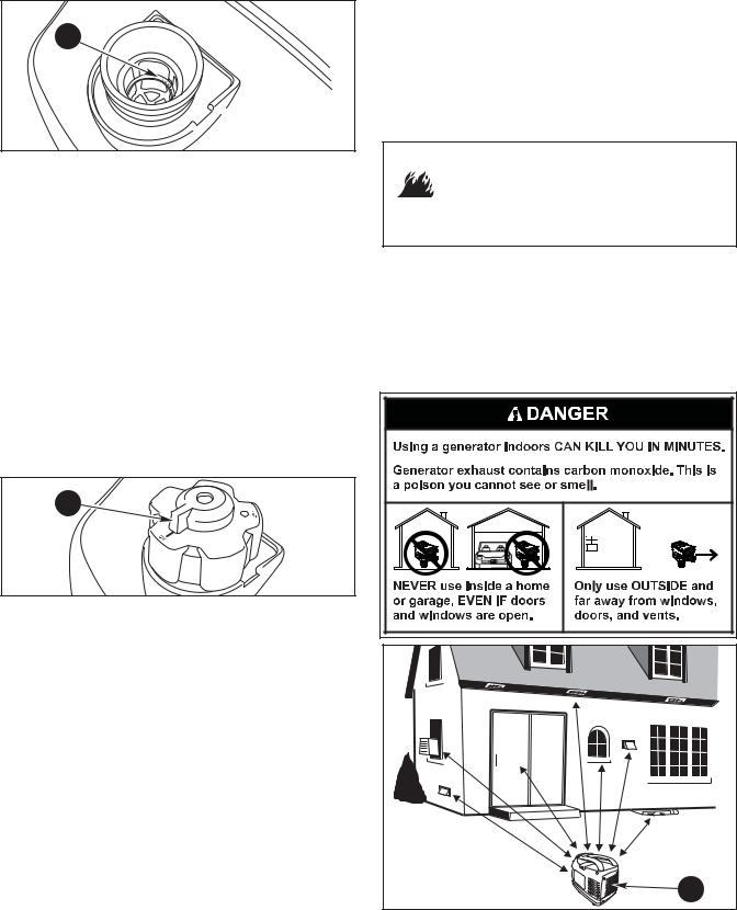
2. Slowly add unleaded fuel to red fuel level indicator (A) in fuel tank. Be careful not to fill above the indicator. This allows adequate space for fuel expansion.
A
3. Install fuel cap and let any spilled fuel evaporate before starting engine.
High Altitude |
|
|
|
• Keep at least 5 ft. (152 cm) clearance on all sides of generator |
At altitudes over 5,000 feet (1524 meters), a minimum |
|
|||
|
including overhead. |
|||
85 octane / 85 AKI (89 RON) gasoline is acceptable. To |
|
Place generator outdoors in an area that will not accumulate |
||
remain emissions compliant, high altitude adjustment is |
|
deadly exhaust gas. DO NOT place generator where exhaust |
||
required. Operation without this adjustment will cause |
|
gas (C) could accumulate and enter inside or be drawn into a |
||
decreased performance, increased fuel consumption, and |
potentially occupied building. Ensure exhaust gas is kept |
|||
increased emissions. See a Briggs & Stratton Authorized |
|
away f om any windows, doors, ventilation intakes, or other |
||
Dealer for high altitude adjustment information. Operation of |
openings that can allow exhaust gas to collect in a confined |
|||
the engine at altitudes below 2,500 feet (762 meters) with |
a ea. P evailing w nds a d air currents should be taken into |
|||
the high altitude kit is not recommended. |
|
|
c nsideration when p siti ning generator. |
|
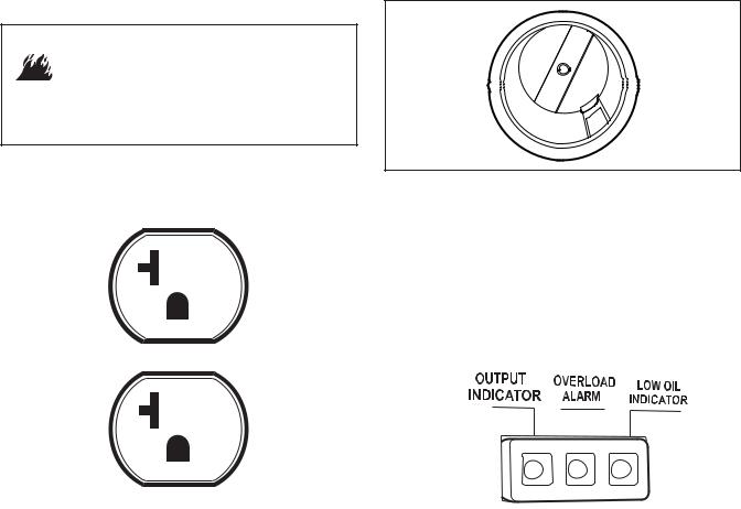
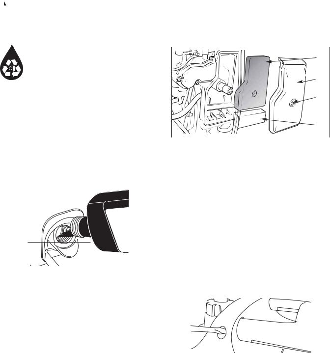
Fuel Tank Cap Vent Lever |
|
|
for |
|
The fuel tank cap is provided with a vent lever (B) |
|
|||
seal he |
|
|||
fuel tank. The vent lever must be in the “ON” p siti |
n f r the |
|
||
engine to run. |
Not |
|
||
B |
|
|||
|
|
|||
When the engine is not in use, leave the vent l v r in the |
|
|
||
“OFF” position to reduce the possibility of fuel leakage. Allow |
|
|||
the engine to cool before turning the vent lever to the “OFF” |
|
|||
position. |
Reproduction |
|||
|
||||
Grounding Fastener
The generator neutral is floating, which means that the AC stator winding is isolated from the grounding fastener and the AC receptacle ground pins. On a floating neutral generator the AC receptacle ground pins are not functional. Electrical devices, such as a GFCI, requiring a functioning AC receptacle ground pin will not operate.
C
8 |
BRIGGSandSTRATTON.COM |
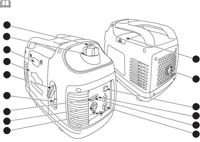
Features and Controls
Read this Operator’s Manual and safety rules before operating your generator.
Compare the illustrations with your generator, to familiarize yourself with the locations of various controls and adjustments. Save this manual for future reference.
A
B
C
D
E
F |
|
for |
|
|
|
N |
|
G |
|
M |
|
|
|
||
H |
|
L |
|
|
|
||
J |
|
|
|
|
|
K |
|
|
|
|
|
A - Fuel Tank Cap Vent Lever — Turn the vent lever to the |
L - Overload Alarm — A red LED light comes on and cuts |
||
“On” position when operating generator. Turn to the |
power to the receptacles when the generator is |
|
|
“Off” position when not in use. |
Not |
overloaded. |
|
|
|
||
B - Fuel Tank — Capacity of 1.0 U.S. gallons (3.7 L). |
M - Low Oil Indicator — A yellow LED light comes on when |
||
C - Choke Lever — Used when starting a cold ngine. |
the oil in the generator drops below a preset level. |
|
|
D - Side Maintenance Cover — Remove to gain acc ss to |
N - POWERSMART Switch— Use this switch to turn the |
||
the air cleaner and oil service. |
|
POWERSMART mode on and off. |
|
E - Recoil Starter — Used to start the engine manually. |
P - Spark Arrester Muffler — Exhaust muffler lowers engine |
||
F - Engine Switch — Set this switch to “On” before using |
noise and is equipped with a spark arrester screen. |
|
|
|
|
||
|
Reproduction |
|
|
recoil starter. Set switch to “Off” to stop engine. Also |
R - Top Maintenance Cover — Remove to gain access to |
||
turns fuel valve on and off. |
|
the spark plug. |
|
G - Output Indicator — A green LED light comes on when the generator is working correctly and producing power at the receptacles.
H - 12 Volt DC Receptacle — Use this receptacle with battery charge cables to charge a 12 Volt battery. This receptacle is protected by a push to reset circuit breaker.
J - Grounding Fastener — Consult your local agency having jurisdiction for grounding requirements in your area.
K - 120 Volt AC, 20 Amp, Duplex Receptacle — May be used to supply electrical power for the operation of 120 Volt AC, 20 Amp, single phase, 60 Hz electrical, lighting, appliance, tool, and motor loads.
Items Not Shown:
Air Cleaner (under side maintenance cover) — Protects engine by filtering dust and debris out of intake air.
Identification Label — Provides model, revision, and serial number of generator. Please have these readily available when calling for assistance.
Oil Fill Cap (under side maintenance cover) — Check and add engine oil here.
9
Cord Sets and Receptacles
Use only high quality, well-insulated, grounded extension cords with the generator’s receptacles. Inspect extension cords before each use.
Check the ratings of all extension cords before you use them. Extension cord sets used should be rated for AC loads 15 Amps or greater. Check operator’s manuals of devices to be powered for the manufacturer’s recommendations.
Keep extension cords as short as possible to minimize voltage drop.
 WARNING Damaged or overloaded electrical cords
could overheat, arc, and burn resulting in death, serious injury, and/or property damage.
•ONLY use cords rated for your loads.
•Follow all safeties on electrical cords.
•Inspect cord sets before each use.
120 Volt AC, 20 Amp, Duplex Receptacle
12 Volt DC Receptacle
The maximum current available for the battery charge circuit is 5 Amps. A DC circuit breaker protects this receptacle from overloads. If an overload occurs, the circuit breaker will trip (push button pops out). Wait a few minutes and push the button in to reset the circuit breaker.
This receptacle allows you to recharge a 12 Volt automotive or utility style storage battery with the battery charge cable provided.
The duplex receptacle is protected against overload by an |
|
|
This receptacle can not be used to crank an engine having a |
||||
internal overload system. |
|
|
|
discharged battery. See Charging a Battery before attempting |
|||
|
|
|
|
|
|
to echa ge a battery. |
|
|
|
|
|
|
|||
|
|
|
|
|
|
NOTICE When using the battery charge circuit, turn the |
|
|
|
|
|
|
|
POWERSMART sw tch to the “Off” position. |
|
|
|
|
|
|
|||
|
|
|
|
|
|
Output Indi a or |
|
|
|
|
|
|
|||
|
|
|
Not |
|
forThe green LED ou put indicator light comes on when the |
||
|
|
|
|
|
generator is operating normally. It indicates that the |
||
|
|
|
|
|
generator is producing power at the receptacles. |
||
|
|
|
|
|
|
|
|
|
|
|
|
|
|
|
|
|
|
|
|
|
|
|
|
|
|
|
|
|
|
|
|
|
|
|
|
|
|
|
|
|
|
|
|
|
|
|
|
Use receptacle to operate 120 Volt AC, single–phase, 60 Hz |
|
|
|
||||
|
|
|
|||||
electrical loads requiring up to 1,600 watts (1.6 kW) at |
|
|
Overload Alarm |
||||
13.3 Amps of current. Use cord sets that are rated for |
|
|
|||||
|
|
The red LED overload alarm light comes on and cuts power |
|||||
125 Volt AC loads at 15 Amps (or greater). |
|
|
|||||
|
|
|
Reproduction |
||||
|
|
|
|
|
|
to the receptacles if you overload the generator. The green |
|
NOTICE Receptacles may be marked with rating value |
|
|
output indicator light will also go off. If the generator was |
||||
|
|
overloaded, you must turn off and unplug all electrical loads, |
|||||
greater than generator output capacity. |
|
|
|
||||
|
|
|
shut down the generator and restart it to continue in normal |
||||
• NEVER attempt to power a device requiring more amperage than |
|
||||||
|
operating mode. |
||||||
generator or receptacle can supply. |
|
|
|
||||
• DO NOT overload the generator. See Don’t Overload Generator.
Low Oil Indicator
The low oil indicator system is designed to prevent engine damage caused by not enough engine oil. If the engine oil level drops below a preset level, the yellow LED low oil indicator light comes on and an oil switch will stop the engine. If the engine stops or the yellow LED low oil indicator light comes on when you pull the recoil handle, check the engine oil level.
BRIGGSandSTRATTON.COM
Operation
Starting the Engine
Disconnect all electrical loads from the generator. Use the following start instructions:
1. Make sure unit is on a level surface.
NOTICE Failure to start and operate the unit on a level surface could cause the unit not to start or shut down during operation.
2.Make sure POWERSMART switch (A) is in “Off” position.
To start engine thereafter:
6B. Grasp recoil handle and pull slowly until slight resistance is felt. Then pull rapidly one time only to start engine.
 WARNING Starter cord kickback (rapid retraction) will pull hand and arm toward engine faster than you
can let go which could cause broken bones, fractures, bruises, or sprains resulting in serious
injury.
•When starting engine, pull cord slowly until resistance is felt and then pull rapidly to avoid kickback.
•NEVER start or stop engine with electrical devices plugged in and turned on.
|
|
|
|
|
|
|
|
|
|
|
• If engine starts, proceed to step 8. |
||||
|
|
|
A |
|
|
|
|
|
|
||||||
|
|
|
|
|
|
|
|
|
• If engine fails to start, proceed to step 7. |
||||||
|
|
|
|
|
|
|
|
|
|
|
|||||
|
|
|
|
|
|
|
|
|
|
7. Move choke lever to half choke position, and pull recoil |
|||||
|
|
|
|
|
|
|
|
|
|
|
handle twice. |
|
|||
|
|
|
|
|
|
|
|
|
|
|
• If engine fails to start, repeat steps 5 thru 6. |
||||
|
|
|
|
|
|
|
|
|
|
8. Slowly move choke lever to “Run” position. If engine |
|||||
3. Turn the engine switch (B) to the “On” position. |
|
||||||||||||||
|
|
|
|
|
falters, move choke lever to half choke position until |
||||||||||
|
|
|
|
|
|
|
|
|
|
|
|||||
|
|
|
|
|
|
|
|
|
|
|
engine runs smoothly, and then to “Run” position. |
||||
|
|
|
|
|
Reproduction |
||||||||||
|
|
|
|
|
B |
|
|
|
NOTICE |
If engine floods, move choke lever to “Run” |
|||||
|
|
|
|
|
|
|
|
|
position and crank u til e gi e starts. |
||||||
|
|
|
|
|
|
|
|
|
NOTICE If engine starts after 3 pulls but fails to run, or if |
||||||
|
|
|
|
|
|
|
|
|
unit shuts down dur ng |
peration, make sure unit is on a |
|||||
|
|
|
|
|
|
|
|
|
level surface and check f |
r proper oil level in crankcase. This |
|||||
|
|
|
|
|
Not |
|
|
|
unit is equipped w h a low oil protection device. If so, oil |
||||||
|
|
|
|
|
|
|
|
must be at proper level for engine to start. |
|||||||
|
|
|
|
|
|
|
|
|
|||||||
4. |
Turn fuel cap vent lever (C) to “On” positi n. |
for |
|
|
|
|
|||||||||
|
|
|
|
|
WARNING Exhaust heat/gases could ignite |
||||||||||
|
|
|
|
|
|
|
|
|
|
|
|||||
|
|
|
|
|
|
|
|
|
|
|
|
|
|
combustibles, structures or damage fuel |
|
|
|
|
|
|
|
|
|
|
|
|
|
|
|
||
|
|
|
C |
|
|
|
|
|
|
|
|||||
|
|
|
|
|
|
|
|
|
|
|
|
tank causing a fire, resulting in death, |
|||
|
|
|
|
|
|
|
|
|
|
|
|
|
|
serious injury and/or property damage. |
|
|
|
|
|
|
|
|
|
|
|
|
|
||||
|
|
|
|
|
|
|
|
|
|
|
|
|
|
||
|
|
|
|
|
|
|
|
|
|
|
|
||||
|
|
|
|
|
|
|
|
|
C |
ntact with muffler area could cause burns resulting in |
|||||
|
|
|
|
|
|
|
|
|
serious injury. |
|
|||||
|
|
|
|
|
|
|
|
|
• DO NOT touch hot parts and AVOID hot exhaust gases. |
||||||
|
|
|
|
|
|
|
|
|
• Allow equipment to cool before touching. |
||||||
5. |
Push choke lever (D) to “Choke” position. |
|
|
|
• Keep at least 5 feet (152 cm) of clearance on all sides of |
||||||||||
|
|
|
|
|
|
|
|
|
|
generator including overhead. |
|||||
|
|
|
|
|
|
|
|
||||||||
|
|
|
|
|
|
|
|
|
• It is a violation of California Public Resource Code, Section |
||||||
|
|
|
|
|
|
|
|
|
|
4442, to use or operate the engine on any forest-covered, |
|||||
|
|
|
|
|
|
|
|
|
|
brush-covered, or grass-covered land unless the exhaust |
|||||
|
|
|
|
|
|
|
|
|
|
system is equipped with a spark arrester, as defined in Section |
|||||
|
|
|
|
|
|
|
|
|
|
4442, maintained in effective working order. Other states or |
|||||
|
|
D |
|
|
|
|
|||||||||
|
|
|
|
|
|
|
|
federal jurisdictions may have similar laws. |
|||||||
|
|
|
|
|
|
|
|
|
|
||||||
|
|
|
|
|
|
|
|
|
|
Contact the original equipment manufacturer, retailer, or dealer |
|||||
|
|
|
|
|
|
|
|
||||||||
NOTICE To help start the engine for the very first time, after |
|
|
|
to obtain a spark arrester designed for the exhaust system |
|||||||||||
|
|
|
installed on this engine. |
|
|||||||||||
running out of fuel or after a long period of storage, fill fuel |
|
|
|
|
|
||||||||||
|
|
|
• Replacement parts must be the same and installed in the same |
||||||||||||
tank as described in Add Fuel. It will require more than |
|
|
|
||||||||||||
|
|
|
|
position as the original parts. |
|||||||||||
several start attempts until the air in the fuel system has |
|
|
|
|
|||||||||||
|
|
|
|
|
|
|
|
|
|
||||||
|
|
|
Connecting Electrical Loads |
||||||||||||
been purged. |
|
|
|
|
|||||||||||
6A. |
Grasp recoil handle and pull slowly until slight resistance |
1. |
Make sure the green output indicator light comes on (it |
||||||||||||
|
is felt. Then pull rapidly to start engine. |
|
|
|
|
|
may take up to three seconds). |
||||||||
|
• If engine starts, proceed to step 8. |
|
2. |
Let engine stabilize and warm up for a few minutes |
|||||||||||
• If engine fails to start, proceed to step 7. |
after starting. |
|
3. Plug in and turn on the desired 120 Volt AC, single |
||
|
||
|
phase, 60 Hz electrical loads. |
11
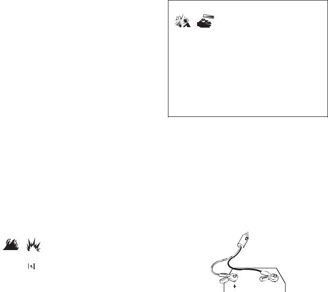
 WARNING Storage batteries give off explosive
hydrogen gas during recharging.
Hydrogen gas stays near battery for a

 long time after battery has been charged. Slightest spark could ignite hydrogen causing explosion resulting in death, serious injury and/or property damage. Battery electrolyte fluid contains acid and is extremely caustic. Contact with battery fluid could cause chemical burns resulting in serious injury and/or property damage.
• DO NOT allow any open flame, spark, heat, or lit cigarette during and for several minutes after charging a battery.
• Wear protective goggles, rubber apron, and rubber gloves.
• DO NOT continue to charge a battery that becomes hot or is fully charged.
• DO NOT leave battery unattended.
• Connect electrical loads in OFF position, then turn ON for |
|
|
To recharge 12 Volt batteries, proceed as follows: |
||||||||
operation. |
|
|
|
1. If necessary, clean battery posts or terminals. |
|||||||
• Turn electrical loads OFF and disconnect from generator before |
|
|
|||||||||
|
|
|
|
|
|
|
|
|
|||
stopping generator. |
|
|
|
|
WARNING Battery posts, terminals and related |
||||||
Stopping the Engine |
|
|
|
accessories contain lead and lead compounds, chemicals |
|||||||
|
|
|
known to the State of California to cause cancer and |
||||||||
1. Turn OFF and unplug all electrical loads from generator |
reproductive harm. Wash hands after handling. |
||||||||||
panel receptacles. NEVER start or stop engine with |
|
|
2. |
Check fluid level in all battery cells. If necessary, add |
|||||||
electrical devices plugged in and turned ON. |
|
|
|
ONLY distilled water to cover separators in battery |
|||||||
2. Move POWERSMART switch to “Off” position. |
|
|
|
cells. DO NOT use tap water. |
|||||||
|
|
3. |
If the ba |
ery s equipped with vent caps, make sure |
|||||||
3. Let engine run at no-load for several minutes to |
|
|
|||||||||
|
|
|
they are |
ns alled and are tight. |
|||||||
stabilize internal temperatures of engine and genera or. |
|
||||||||||
4. |
Conne t battery charge cable clamp with red handle to |
||||||||||
4. Turn engine switch to the “Off” position. |
|
|
|||||||||
|
for |
|
|
|
|
|
|||||
|
|
|
|
|
|
|
|
||||
WARNING Fuel and its vapors are extremely flammable |
|
|
|
battery post or terminal indicated by Positive, POS or (+). |
|||||||
|
|
|
|
|
|
|
|
|
|||
and explosive which could cause burns, |
|
|
|
|
|
|
|
|
|
||
fire or explosion resulting in death, |
|
|
|
|
|
|
|
|
|
||
serious injury and/or property damage. |
|
|
|
|
|
|
|
|
|
||
• DO NOT stop engine by moving choke controlNotto “Choke” |
|
|
|
|
|
|
|
|
|
||
position ( ). |
|
|
|
|
|
|
|
|
|
|
|
5. Turn fuel cap vent lever to the “Off” position. |
|
|
|
|
|
|
|
|
|
||
POWERSMART Mode |
|
|
|
|
|
|
|
|
|
|
|
|
|
|
|
|
|
|
|
|
|
||
|
|
|
|
|
|
|
|
|
|
||
|
|
|
5. Connect battery charge cable clamp with black handle |
||||||||
This feature is designed to greatly improve fuel economy. |
|
|
|||||||||
|
|
|
to battery post or terminal indicated by Negative, NEG, |
||||||||
When this switch is turned ON, the engine speed will |
|
|
|
or (–). |
|
|
|
|
|
||
increase as electrical loads are connected, and decreased as |
|
|
6. Connect battery charge cable connector plug to the |
||||||||
electrical loads are removed. |
Reproduction |
||||||||||
12 Volt DC panel receptacle.
With the switch off, the engine will run at full governed speed. Always have the switch OFF when starting and stopping the engine.
NOTICE Always have the switch OFF when starting or stopping the generator or when using the DC receptacle.
7.Start generator as described in Starting The Engine. Let the engine run while battery recharges.
NOTICE Normally a period of 30 to 120 minutes is sufficient to recharge a weak battery.
8.When battery has charged, shut down engine as described in Stopping The Engine.
Charging a Battery
Your generator has the capability of recharging a discharged 12 Volt automotive or utility style storage battery.
NOTICE
•Not for use with any other type of battery.
•DO NOT use the unit to charge any 6 Volt batteries.
•DO NOT use the unit to crank an engine having a discharged battery.
9.Remove the battery charging cable from the generator and then disconnect from the battery posts.
NOTICE Use an automotive hydrometer to test battery state of charge and condition. Follow the hydrometer manufacturer’s instructions carefully. Generally, a battery is considered to be at 100% state of charge when specific gravity of its fluid (as measured by hydrometer) is 1.260 or higher.
12 |
BRIGGSandSTRATTON.COM |

Don’t Overload Generator |
|
|
|
|
NEVER add more loads than the generator capacity. Take |
||||
Capacity |
|
|
|
|
|
special care to consider surge loads in generator capacity, as |
|||
|
|
|
|
|
described above. |
|
|
||
You must make sure your generator can supply enough |
|
|
|
|
|
||||
|
|
Wattage Reference Guide |
|
||||||
rated (running) and surge (starting) watts for the items you |
|
|
|||||||
will power at the same time. Follow these simple steps: |
|
|
|
Rated* |
Additional |
||||
1. |
Select the items you will power at the same time. |
|
|
Tool or Appliance |
(Running) |
Surge |
|||
2. Total the rated (running) watts of these items. This is |
|
|
|
Watts |
(Starting) |
||||
|
|
|
|
Watts |
|||||
|
the amount of power your generator must produce to |
|
|
|
|
||||
|
|
|
|
|
|
||||
|
|
|
Essentials |
|
|
||||
|
keep your items running. See Wattage Reference Guide. |
|
|
|
|||||
|
|
|
|
|
|||||
|
|
Light Bulb - 75 watt |
75 |
— |
|||||
3. Estimate how many surge (starting) watts you will need. |
|
||||||||
|
|
|
|
||||||
|
Deep Freezer |
500 |
500 |
||||||
|
Surge wattage is the short burst of power needed to |
|
|
||||||
|
start electric motor-driven tools or appliances such as a |
|
Sump Pump |
800 |
1200 |
||||
|
circular saw or refrigerator. Because not all motors start |
|
|
|
|
||||
|
|
Refrigerator/Freezer - 18 cf |
800 |
1600 |
|||||
|
at the same time, total surge watts can be estimated by |
|
|
|
|
||||
|
|
Water Well Pump - 1/3 hp |
1000 |
2000 |
|||||
|
adding only the item(s) with the highest additional surge |
|
|||||||
|
|
Heating/Cooling |
|
|
|||||
|
watts to the total rated watts from step 2. |
|
|
|
|
||||
|
|
|
|
|
|
||||
|
|
|
Window AC - 10,000 BTU |
1200 |
1800 |
||||
Example: |
|
|
|
|
|
||||
|
|
|
|
|
|
|
|
||
|
|
|
|
|
Window Fan |
300 |
600 |
||
|
|
|
|
|
|
|
|||
|
|
Rated (Running) |
|
Additional Surge |
|
Furnace Fan Blower - 1/2 hp |
800 |
1300 |
|
|
|
|
|
Reproduction |
|
|
|||
Tool or Appliance |
Watts |
|
(Starting) Watts |
|
Kitchen |
|
|
||
Window Fan |
300 |
|
600 |
|
|
|
|
|
|
|
|
|
Mic owave Oven - 1000 Watt |
1000 |
— |
||||
|
|
|
|
|
|
|
|||
Deep Freezer |
500 |
|
500 |
|
|
|
|
|
|
|
|
|
C ffee Maker |
1500 |
— |
||||
|
|
|
|
|
|
|
|||
Television |
500 |
|
— |
|
|
|
|
|
|
|
|
|
Electric S ove - S ngle Element |
1500 |
— |
||||
|
|
|
|
|
|
|
|||
Security System |
180 |
|
— |
|
|
|
|
|
|
|
|
|
Hot Plate |
2500 |
— |
||||
|
|
|
|
|
|
|
|||
|
|
|
|
Not |
|
|
|
|
|
Light (75 Watts) |
75 |
|
— |
for |
|
|
|||
|
|
|
|
|
|
|
Family Room |
|
|
|
|
1555 Total |
|
600 Highest |
|
|
|
|
|
|
|
|
|
|
DVD/CD Player |
100 |
— |
||
|
|
Running Watts |
|
Surge Watts |
|
|
|
|
|
|
|
|
|
|
VCR |
100 |
— |
||
Total Rated (Running) Watts |
= 1555 |
|
|
||||||
|
|
Stereo Receiver |
450 |
— |
|||||
Highest Additional Surge Watts |
= 600 |
|
|
|
|
|
|||
|
|
C lor Television - 27 in |
500 |
— |
|||||
Total Generator Output Required |
= 2155 |
|
|
||||||
|
|
|
|
|
|||||
|
|
Personal Computer w/17 in |
800 |
— |
|||||
|
|
|
|
|
|
|
|||
Power Management |
|
|
|
|
|
monitor |
|
|
|
|
|
|
|
|
|
|
|
||
To prolong the life of your generator and attach d d vic s, it |
|
Other |
|
|
|||||
is important to take care when adding electrical loads to your |
|
Security System |
180 |
— |
|||||
generator. There should be nothing connect d to the |
|
|
AM/FM Clock Radio |
300 |
— |
||||
generator outlets before starting its engine. The correct and |
|
|
|
|
|||||
|
Garage Door Opener - 1/2 hp |
480 |
520 |
||||||
safe way to manage generator power is to sequentially add |
|
|
|||||||
|
|
|
|
|
|||||
|
|
Electric Water Heater - 40 gallon |
4000 |
— |
|||||
loads as follows: |
|
|
|
|
|
||||
|
|
|
|
|
|
|
|
||
|
|
|
|
|
DIY/Job Site |
|
|
||
1. With nothing connected to the generator, start the |
|
|
|
|
|||||
|
|
Quartz Halogen Work Light |
1000 |
— |
|||||
|
engine as described in this manual. |
|
|
|
|
||||
2. Plug in and turn on the first load, preferably the largest |
|
Airless Sprayer - 1/3 hp |
600 |
1200 |
|||||
|
|
|
|
||||||
|
load you have. |
|
|
|
|
|
Reciprocating Saw |
960 |
960 |
3. |
Permit the generator output to stabilize (engine runs |
|
|
Electric Drill - 1/2 hp |
1000 |
1000 |
|||
|
smoothly and attached device operates properly). |
|
|
Circular Saw - 7-1/4 in |
1500 |
1500 |
|||
4. |
Plug in and turn on the next load. |
|
|
|
|
|
|
|
|
|
|
|
|
Miter Saw - 10 in |
1800 |
1800 |
|||
5. |
Again, permit the generator to stabilize. |
|
|
Table Planer - 6 in |
1800 |
1800 |
|||
|
|
|
|
|
|
|
|||
6. |
Repeat steps 4 and 5 for each additional load. |
|
|
Table Saw/Radial Arm Saw - 10 in |
2000 |
2000 |
|||
|
|
|
|
|
|
|
Air Compressor - 1-1/2 hp |
2500 |
2500 |
* Wattages listed are approximate only. Check tool or appliance for actual wattage.
13

Maintenance
Emissions Control
Maintenance, replacement, or repair of the emissions Maintenance Schedule control devices and systems may be performed by any
Follow the hourly or calendar intervals, whichever occurs
non-road engine repair establishment or individual.
first. More frequent service is required when operating in
However, to obtain ”no charge” emissions control service,
adverse conditions noted below.
the work must be performed by a factory authorized dealer. See the Emissions Warranty.
Every 8 Hours or Daily
|
|
|
|
|
|
Generator Maintenance |
||
|
• |
Clean debris |
|
|
|
|||
|
|
|
|
Generator maintenance consists of keeping the unit clean |
||||
|
|
|
|
|
|
|||
|
• |
Check engine oil level |
|
|
|
|||
|
|
|
|
and dry. Operate and store the unit in a clean dry |
||||
|
|
|
|
|
|
|||
|
First 10 Hours |
|
|
|
environment where it will not be exposed to excessive dust, |
|||
|
|
|
|
|
|
dirt, moisture, or any corrosive vapors. Cooling air slots in |
||
|
• |
Change engine oil |
|
|
|
|||
|
|
|
|
the generator must not become clogged with snow, leaves, |
||||
|
|
|
|
|
|
|||
|
Every 50 Hours or 3 Months |
|
|
|
or any other foreign material. |
|||
|
|
|
|
|
|
NOTICE DO NOT use water or other liquids to clean |
||
|
• |
Service engine air cleaner and breather filter1 |
|
|
||||
|
|
|
generator. Liquids can enter engine fuel system, causing |
|||||
|
Every 100 Hours or 6 Months |
|
|
|
poor performance and/or failure to occur. In addition, if |
|||
|
|
|
|
|
|
liquid enters generator through cooling air slots, some of the |
||
|
• |
Clean fuel strainer |
|
|
|
|||
|
|
|
|
liquid will be retained in voids and cracks of the rotor and |
||||
|
|
|
|
|
|
|||
• NEVER operate generator without protectiveReproductionhousing or covers to |
||||||||
|
• |
Change engine oil1 |
|
|
|
stator winding insulation. Liquid and dirt buildup on the |
||
|
|
|
|
for |
|
|
||
|
• |
Service spark plug |
|
|
|
gene ator internal wi |
di gs will eventually decrease the |
|
|
|
|
|
|
|
insulation resistance |
f these wi dings. |
|
|
• |
Inspect muffler and spark arrester |
|
|
|
Cleaning |
|
|
|
Every 250 Hours or Yearly |
|
|
|
Daily or before use, look around and underneath the |
|||
|
• |
Check valve clearance |
Not |
|
|
generator for signs of oil or fuel leaks. Clean accumulated |
||
1 |
Service more often under dirty or dusty conditions. |
|
|
|
debris from inside and outside the generator. Keep the |
|||
|
|
|
|
|
|
linkage, spring and other engine controls clean. Keep the |
||
General Recommendations |
|
|
|
area aro |
nd and behind the muffler free from any |
|||
Regular maintenance will improve the performance and |
|
|
combustible debris. Inspect cooling air slots and openings |
|||||
|
|
n generator. These openings must be kept clean and |
||||||
extend the life of the generator. See any authorized dealer f |
|
|||||||
|
un bstructed. |
|
||||||
service. |
|
|
|
|
||||
|
|
|
Engine parts should be kept clean to reduce the risk of |
|||||
The generator’s warranty does not cover items that have |
|
|
||||||
|
|
overheating and ignition of accumulated debris: |
||||||
been subjected to operator abuse or neglig nce. To r c ive |
|
|||||||
|
• Use a damp cloth to wipe exterior surfaces clean. |
|||||||
full value from the warranty, the operator must maintain the |
|
|||||||
generator as instructed in this manual. |
|
|
|
NOTICE |
Improper treatment of generator could damage it |
|||
|
|
|
|
|
|
|||
|
NOTICE Improper treatment of generator could damage it |
|
and shorten its life. |
|
||||
|
and shorten its life. |
|
|
|
• DO NOT expose generator to excessive moisture, dust, dirt, or |
|||
|
|
|
|
|
|
corrosive vapors. |
|
|
|
assure proper cooling. |
|
|
|
• DO NOT insert any objects through cooling slots. |
|||
Some adjustments will need to be made periodically to properly maintain your generator.
All service and adjustments should be made at least once each season. Follow the requirements in the Maintenance Schedule chart above.
NOTICE Once a year you should clean or replace the spark plug and replace the air filter. A new spark plug and clean air filter assure proper fuel-air mixture and help your engine run better and last longer.
•Use a soft bristle brush to loosen caked on dirt or oil.
•Use a vacuum cleaner to pick up loose dirt and debris.
14 |
BRIGGSandSTRATTON.COM |
Cleaning Fuel Strainer
The fuel strainer helps prevent debris from entering the fuel system.
Clean the fuel strainer as follows:
1.Make sure generator is on a level surface.
2.Remove the fuel cap (A) and fuel strainer (B).
A
B
3.Wash fuel strainer in liquid detergent and water.
4.Wipe fuel strainer clean with a clean, dry cloth.
5.Carefully reinstall the fuel strainer and fuel cap.
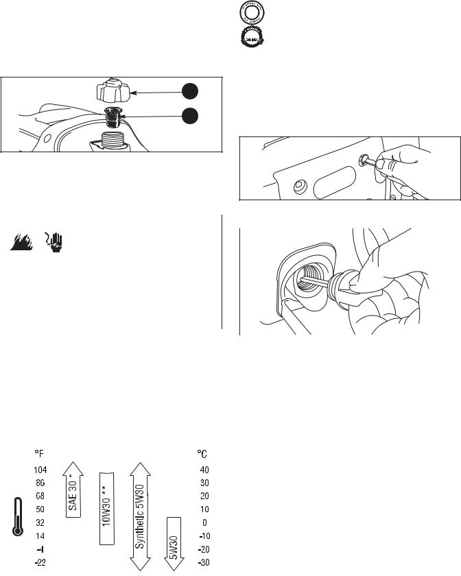
NOTICE Synthetic oil meeting ILSAC GF-2, API


 certification mark and API service symbol with
“SJ/CF ENERGY CONSERVING” or higher, is an


 acceptable oil at all temperatures. Use of synthetic


 oil does not alter required oil change intervals.
Checking Oil Level
Oil level should be checked prior to each use or at least every 8 hours of operation. Keep oil level maintained.
1.Make sure generator is on a level surface.
2.Loosen the side maintenance cover screws and remove the side maintenance cover.
Engine Maintenance |
|
|
3. |
Clean area around oil fill and remove oil fill cap. |
||||||||
|
|
|
|
|
|
|
|
|
4. |
Verify oil is at the point of overflowing at oil fill opening. |
||
|
WARNING Unintentional sparking could cause fire or |
|
||||||||||
|
|
|
|
|
||||||||
|
|
|
|
|
electric shock resulting in death or |
|
|
|
|
|||
|
|
|
|
|
serious injury. |
Reproduction |
||||||
WHEN ADJUSTING OR MAKING REPAIRS TO YOUR GENERATOR |
for |
|
||||||||||
• Disconnect the spark plug wire from the spark plug and place |
|
|||||||||||
|
the wire where it cannot contact spark plug. |
|
||||||||||
WHEN TESTING FOR ENGINE SPARK |
|
|
|
|||||||||
• Use approved spark plug tester. |
|
|
|
|||||||||
• DO NOT check for spark with spark plug removed. |
|
|
|
|
||||||||
Oil |
Not |
5. |
Replace and tighten oil fill cap. |
|||||||||
Oil Recommendations |
6. |
Reinstall the side maintenance cover and hand tighten |
||||||||||
|
|
|
|
|
|
|
|
|
the cover screws. |
|||
We recommend the use of Briggs & Stratton Warranty |
|
|
|
|
||||||||
Certified oils for best performance. Other high-quality |
|
|
Adding Engine Oil |
|||||||||
detergent oils are acceptable if classified for s rvice SF, SG, |
|
|
||||||||||
1. |
Make sure generator is on a level surface. |
|||||||||||
SH, SJ or higher. DO NOT use special additiv s. |
||||||||||||
Outdoor temperatures determine the proper oil viscosity for |
2. |
Repeat steps 2 through 4 to check oil level as described |
||||||||||
the engine. Use the chart to select the best viscosity for the |
|
|
|
in Checking Oil Level. |
||||||||
outdoor temperature range expected. |
|
|
3. |
If needed, slowly pour oil into oil fill opening to the |
||||||||
|
|
|
|
|
|
|
|
|
|
|
point of overflowing at oil fill. |
|
|
|
|
|
|
|
|
|
4. |
Replace and tighten oil fill cap. |
|||
|
|
|
|
|
|
|
|
5. |
Reinstall the side maintenance cover and hand tighten |
|||
|
|
|
|
|
|
|
|
|
|
|
the cover screws. |
|
|
|
|
|
|
|
|
|
|
|
|
|
|
|
|
|
|
|
|
|
|
|
|
|
|
|
|
|
|
|
|
|
|
|
|
|
|
|
|
|
|
|
|
|
|
|
|
|
|
|
|
|
|
|
|
|
|
|
|
|
|
|
|
|
|
* Below 40°F (4°C) the use of SAE 30 will result in hard starting.
**Above 80°F (27°C) the use of 10W30 may cause increased oil consumption. Check oil level more frequently.
15
Changing Engine Oil |
Service Air Cleaner |
If you are using your generator under extremely dirty or |
Your engine will not run properly and may be damaged if |
dusty conditions, or in extremely hot weather, change the oil |
you run it with a dirty air cleaner. Service more often if |
more often. |
operating under dirty or dusty conditions. |
CAUTION Avoid prolonged or repeated skin contact |
|
To service the air cleaner, follow these steps: |
|||
with used motor oil. |
|
1. Loosen the side maintenance cover screws and remove |
|||
• Used motor oil has been shown to cause skin cancer in certain |
|
||||
|
the side maintenance cover. |
||||
laboratory animals. |
|
||||
|
2. Loosen air cleaner cover screw (A) and remove air |
||||
• Thoroughly wash exposed areas with soap and water. |
|
||||
|
cleaner cover (B). |
||||
|
|
||||
KEEP OUT OF REACH OF CHILDREN. DON’T |
|||||
|
|
|
|||
|
|
|
|||
POLLUTE. CONSERVE RESOURCES. RETURN |
|
C |
|
||
USED OIL TO COLLECTION CENTERS. |
|
|
|
||
|
|
|
|||
|
|
|
|
||
|
|
|
B |
|
|
Change the oil while the engine is still warm from running, |
|
|
|
||
|
|
|
|||
as follows: |
|
A |
|
||
1. Make sure generator is on a level surface. |
|
|
|
||
|
|
|
|||
2. |
Loosen the side maintenance cover screws and remove |
|
|
|
|
|
|||
|
the side maintenance cover. |
|
|
|
|
|
|
|
|
|
|
|
|
|
|
|
D |
|
|
8. |
Reinstall the side maintenance coverReproduand hand tighten ction |
|
|||||||
3. |
Clean area around oil fill and remove oil fill cap. |
|
|
|
|
|
|
|
|
|
|
|
|
|
|
|
|||
4. |
Tip your generator to drain oil from oil fill into a |
|
|
3. |
Ca efully rem |
ve f am air cleaner (C) by pulling it out |
|||
|
suitable container making sure you tip your unit toward |
|
towards y u. |
|
|
|
|||
|
the oil filler neck. When crankcase is empty, return |
|
|
4. |
Carefully rem |
ve breather filter (D) by pulling it out |
|||
|
generator to upright position. |
Not |
|||||||
|
|
towards you. |
|
|
|
||||
|
|
|
|
|
|
||||
5. |
Slowly pour oil (about 13.5 oz.) into oil fill opening |
o for5. Wash foam air cleaner and breather filter in liquid |
|||||||
|
the point of overflowing at oil fill cap. DO NOT verfill. |
|
detergent and water only. Squeeze dry in a clean cloth. |
||||||
|
|
|
|
|
6. |
SATURATE foam air cleaner in clean engine oil and |
|||
|
|
|
|
|
|
squeeze in a clean cloth to remove excess oil. |
|||
|
|
|
|
|
7. |
Reinstall clean or new foam air cleaner inside base. |
|||
|
|
|
|
|
8. |
Reinstall clean or new breather filter inside base. |
|||
|
|
|
|
|
9. |
Reinstall the air cleaner cover and tighten screw. |
|||
|
|
|
|
|
10. |
Reinstall the side maintenance cover and hand tighten |
|||
|
|
|
|
|
|
the cover screws. |
|||
|
|
|
|
|
Service Spark Plug |
|
|
|
|
6. |
Reinstall oil fill cap. Finger tighten cap securely. |
|
|
|
|
|
|||
|
|
Changing the spark plug will help your engine to start easier |
|||||||
7. |
Wipe up any spilled oil. |
|
|
|
|||||
|
|
|
and run better. |
|
|
|
|||
|
|
|
|
|
|
|
|
||
|
the cover screws. |
|
|
|
1. |
Loosen the four handle screws and remove handle. |
|||
|
|
|
|
|
|
|
|
|
|
|
|
|
|
|
|
|
|
|
|
|
|
|
|
|
|
|
|
|
|
16 |
BRIGGSandSTRATTON.COM |
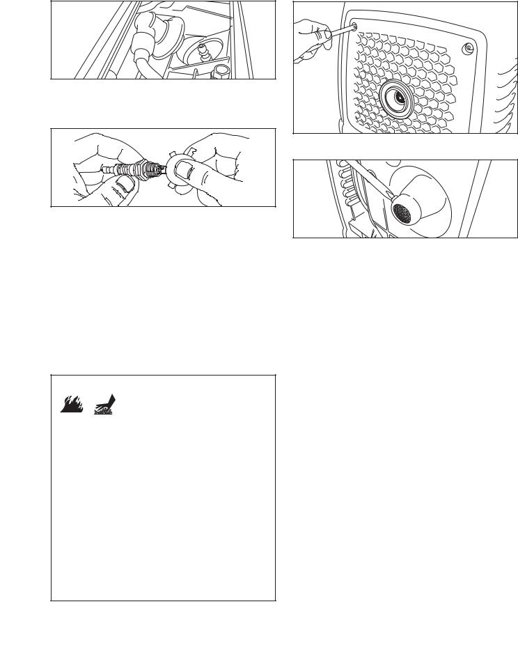
2.Remove top maintenance cover.
3.Clean area around spark plug and remove spark plug boot.
4.Remove spark plug and inspect spark plug.
5.Check electrode gap with wire feeler gauge and reset spark plug gap to recommended gap if necessary (see
Specifications).
Clean and inspect the spark arrester as follows:
1.To remove muffler guard, remove four screws that connects guard to generator.
2.Remove screw that attaches spark arrester screen to muffler. Remove spark arrester screen.
6. Replace spark plug if electrodes are pitted, burned or |
|
|
||||
|
porcelain is cracked. Use the recommended |
|
|
|||
|
replacement plug. See Specifications. |
3. Inspect screen and btain a replacement if torn, |
||||
7. Install spark plug and tighten firmly. Reinstall spark |
||||||
perfora ed or o herwise damaged. DO NOT use a |
||||||
|
plug boot. |
|
|
|||
|
|
|
defe |
ive s reen. If screen is not damaged, clean it with |
||
|
|
|
|
|||
8. |
Reinstall top maintenance cover. |
|
fora br |
sh. |
||
9. |
Reinstall handle and tighten the four handle screws. |
4. Reattach screen to muffler. Reattach muffler guard. |
||||
Inspect Muffler and Spark Arrester |
|
Check Valve Clearance |
||||
Inspect the muffler for cracks, corrosion, or other damage. |
Regular valve clearance check and adjustment will improve |
|||||
Remove the spark arrester, if equipped, and inspect for |
performance and extend engine life. This procedure cannot |
|||||
|
|
|
Not |
be done without partial engine disassembly and the use of |
||
damage or carbon blockage. If replacement parts are |
||||||
required, make sure to use only original equipment |
special tools. For this reason we recommend that you have |
|||||
replacement parts. |
|
|
an authorized Service Dealer check and adjust valve |
|||
|
WARNING Exhaust heat/gases could ignite |
clearance at recommended intervals (see Maintenance |
||||
|
|
combustibles, structures or damage fuel |
Schedule in the Maintenance section). |
|||
|
|
tank causing a fire, resulting in death, |
|
|
||
|
|
serious injury and/or property damage. |
|
|
||
Contact with muffler area could cause burns resulting in |
|
|
||||
serious injury. |
|
Reproduction |
||||
|
|
|
|
|||
•DO NOT touch hot parts and AVOID hot exhaust gases.
•Allow equipment to cool before touching.
•Keep at least 5 feet (152 cm) of clearance on all sides of generator including overhead.
•It is a violation of California Public Resource Code, Section 4442, to use or operate the engine on any forest-covered, brush-covered, or grass-covered land unless the exhaust system is equipped with a spark arrester, as defined in Section 4442, maintained in effective working order. Other states or federal jurisdictions may have similar laws.
Contact the original equipment manufacturer, retailer, or dealer to obtain a spark arrester designed for the exhaust system installed on this engine.
•Replacement parts must be the same and installed in the same position as the original parts.
17
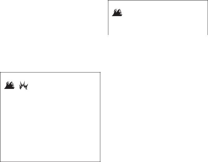
Storage
The generator should be started at least once every seven days and allowed to run at least 30 minutes. If this cannot be done and you must store the unit for more than 30 days, use the following guidelines to prepare it for storage.
Generator Storage
• Clean the generator as outlined in Cleaning.
• Check that cooling air slots and openings on generator are open and unobstructed.
Long Term Storage Instructions
Fuel can become stale when stored over 30 days. Stale fuel causes acid and gum deposits to form in the fuel system or on essential carburetor parts. To keep fuel fresh, use Briggs & Stratton FRESH START® fuel stabilizer, available as a liquid additive or a drip concentrate cartridge.
If gasoline in the engine has not been treated with a fuel stabilizer, it must be drained into an approved container. Run the engine until it stops from lack of fuel. The use of a fuel stabilizer in the storage container is recommendedNoto maintain freshness.
There is no need to drain gasoline from the engine if a fuel |
|
• DO NOT place a storage cover over a hot generator. |
|
|
• Let equipment cool for a sufficient time before placing the |
||
stabilizer is added according to instructions. Run the engine |
|
||
for 2 minutes to circulate the stabilizer throughout the fuel |
|
cover on the equipment. |
|
|
|
||
system. The engine and fuel can then be stored up to |
|
4. Store generator in clea , dry area. |
|
24 months. |
|
for |
|
|
|
||
|
Reproduction |
||
 WARNING Fuel and its vapors are extremely flammable and explosive which could cause burns,
fire or explosion resulting in death, serious injury and/or property damage.
WHEN STORING FUEL OR EQUIPMENT WITH FUEL IN TANK
• Store away from furnaces, stoves, water heaters, clothes d ye s or other appliances that have pilot light or other ignition sou ce because they could ignite fuel vapors.
• Turn generator engine OFF and let it cool at l ast 2 minut s before removing fuel cap. Loosen cap slowly to relieve pressure in tank.
• Keep fuel away from sparks, open flames, pilot lights, heat, and other ignition sources.
• Check fuel lines, tank, cap and fittings frequently for cracks or leaks. Replace if necessary.
• DO NOT light a cigarette or smoke.
18 |
BRIGGSandSTRATTON.COM |

Troubleshooting
Problem |
Cause |
|
Correction |
|
||
|
1. |
Red overload alarm light is on. Generator |
1. |
See Don’t Overload Generator in |
||
|
|
is overloaded. |
|
|
Operation section. Shut down |
|
|
|
|
|
|
generator and restart. |
|
Engine is running, but no AC |
2. |
Green output indicator light not on. Fault |
2. |
Contact authorized service facility. |
||
output is available. |
|
in generator. |
|
|
|
|
|
3. |
Poor connection or defective cord set. |
3. |
Check and repair. |
||
|
4. |
Connected device is bad. |
4. |
Connect another device that is in good |
||
|
|
|
|
|
condition. |
|
|
|
|
|
|
||
|
1. |
Short circuit in a connected load. |
1. |
Disconnect shorted electrical load. |
||
Engine runs good at no-load but |
2. |
Engine speed is too slow. |
2. |
Contact authorized service facility. |
||
“bogs down” when loads are |
3. |
Generator is overloaded. |
3. |
See Don’t Overload Generator in |
||
connected. |
|
|
|
|
Operation section. |
|
|
4. |
Shorted generator circuit. |
4. |
Contact authorized service facility. |
||
|
|
|
|
|
||
|
1. |
Engine switch set to “Off”. |
1. |
Set engine switch to “On”. |
||
|
2. |
Fuel cap vent lever is in “Off” position. |
2. |
Turn fuel cap vent lever to “On” |
||
|
Reproduction |
|||||
|
|
|
for |
|
position. |
|
|
3. |
Low oil indicator light comes on. Low oil |
3. |
Fill cra |
kcase to proper level or place |
|
|
|
level. |
|
|
ge erator on level surface. |
|
|
4. |
Dirty air cleaner. |
|
4. |
Clean |
r replace air cleaner. |
|
5. |
Out of fuel. |
|
5. |
F ll fuel tank. |
|
|
6. |
Not |
|
6. |
Drain fuel tank and carburetor; fill with |
|
Engine will not start; shuts |
|
|
|
|
fresh fuel. |
|
down when running or starts |
7. |
Spark plug wire n t connected to spark |
7. |
Connect wire to spark plug. |
||
and runs rough. |
|
plug. |
|
|
|
|
|
8. |
Bad spark plug. |
|
8. |
Replace spark plug. |
|
|
9. |
Water in fuel. |
|
9. |
Drain fuel tank and carburetor; fill with |
|
|
|
|
|
|
fresh fuel. |
|
|
10. |
Flooded. |
|
10. |
Wait 5 minutes and re-crank engine. |
|
|
11. |
Exc ssiv ly rich fuel mixture. |
11. |
Contact authorized service facility. |
||
|
12. |
Intake valve stuck open or closed. |
12. |
Contact authorized service facility. |
||
|
13. |
Engine has lost compression. |
13. |
Contact authorized service facility. |
||
|
|
|
|
|
|
|
|
1. |
Load is too high. |
|
1. |
See Don’t Overload Generator in |
|
Engine lacks power. |
|
|
|
|
Operation section. |
|
|
2. |
Dirty air filter. |
|
2. |
Replace air filter. |
|
|
|
|
||||
Engine “hunts” or falters. |
Carburetor is running too rich or too lean. |
Contact authorized service facility. |
||||
|
|
|
|
|
|
|
19

Wiring Diagram
Not |
for |
|
|
Reproduction |
|
20 |
BRIGGSandSTRATTON.COM |
Warranties
|
|
|
|
The following are specific provisions relative to your |
||||
California, U.S. EPA, and Briggs & Stratton |
|
Emissions Control Warranty Coverage. It is in addition to the |
||||||
Corporation Emissions Control Warranty |
|
B&S engine warranty for non-regulated engines found in the |
||||||
|
Operator’s Manual. |
|||||||
Statement |
|
|
||||||
|
|
1. |
Warranted Emissions Parts |
|||||
|
|
|
|
|||||
Your Warranty Rights And Obligations |
|
|
|
Coverage under this warranty extends only to the parts |
||||
The California Air Resources Board, U.S. EPA, and Briggs & |
|
|
listed below (the emissions control systems parts) to |
|||||
|
|
the extent these parts were present on the engine |
||||||
Stratton (B&S) are pleased to explain the emissions control |
|
|
||||||
|
|
purchased. |
||||||
system warranty on your Model Year 2011-2012 |
|
|
||||||
|
|
a. |
Fuel Metering System |
|||||
engine/equipment. In California, new small off-road engines |
|
|
||||||
and large spark ignited engines less than or equal to 1.0 liter |
|
|
|
• |
Cold start enrichment system (soft choke) |
|||
must be designed, built, and equipped to meet the State’s |
|
|
|
• |
Carburetor and internal parts |
|||
stringent anti-smog standards. B&S must warrant the |
|
|
|
|||||
|
|
|
• |
Fuel pump |
||||
emissions control system on your engine/equipment for the |
|
|
|
|||||
|
|
|
• |
Fuel line, fuel line fittings, clamps |
||||
periods of time listed below provided there has been no abuse, |
|
|
||||||
neglect, or improper maintenance of your engine or equipment. |
|
|
• |
Fuel tank, cap and tether |
||||
Your emissions control system may include parts such as |
|
|
|
• |
Carbon canister |
|||
the carburetor or fuel injection system, fuel tank, ignition |
|
|
b. |
Air Induction System |
||||
system, and catalytic converter. Also included may be hoses, |
|
|||||||
|
|
• |
Air cleaner |
|||||
belts, connectors, sensors, and other emissions-related |
|
|
|
|||||
for |
|
• |
Intake ma ifold |
|||||
assemblies. Where a warrantable condition exists, B&S will |
|
|||||||
repair your engine/equipment at no cost to you including |
|
• |
Purge and ve t li e |
|||||
diagnosis, parts, and labor. |
|
c. |
Igni on Sys em |
|||||
|
|
|
||||||
Manufacturer’s Warranty Coverage: |
|
|
• |
Spark plug(s) |
||||
Small off-road engines and large spark ignited engines less |
|
• |
Magne o ignition system |
|||||
than or equal to 1.0 liter are warranted for two years. If any |
d. |
Catalyst System |
||||||
|
|
|||||||
emissions-related part on your engine/equipment is |
|
|
|
• |
Catalytic converter |
|||
defective, the part will be repaired or replaced by B&S. |
|
|
|
|||||
|
|
|
• |
Exhaust manifold |
||||
|
|
|
|
|
|
|||
Owner’s Warranty Responsibilities: |
|
|
|
|
• |
Air injection system or pulse valve |
||
• |
As the engine/equipment owner, you are responsible |
|
|
e. |
Miscellaneous Items Used in Above Systems |
|||
|
|
Not |
|
|
||||
|
for the performance of the required maintenance listed |
|
|
|
• |
Vacuum, temperature, position, time sensitive |
||
|
in your owner’s manual. B&S recommends that you |
|
|
|
||||
|
|
|
|
|
valves and switches |
|||
|
retain all receipts covering maintenance on your |
|
|
|
|
|||
|
|
|
|
• |
Connectors and assemblies |
|||
|
engine/equipment, but B&S cannot deny warranty |
|
|
|
||||
|
|
2. |
Length of Coverage |
|||||
|
solely for the lack of receipts or your failure to ensure |
|
||||||
|
the performance of all scheduled maintenance. |
|
|
For a period of two years from date of original |
||||
• |
As the engine/equipment owner, you should however |
|
|
purchase, B&S warrants to the original purchaser and |
||||
|
|
Reproductioneach subsequent purchaser that the engine is designed, |
||||||
|
be aware that B&S may deny you warranty coverage if |
|
|
built, and equipped so as to conform with all applicable |
||||
|
your engine/equipment or a part has failed due to |
|
|
|||||
|
|
|
regulations adopted by the Air Resources Board; that it |
|||||
|
abuse, neglect, improper maintenance, or unapproved |
|
|
|||||
|
|
|
is free from defects in material and workmanship that |
|||||
|
modifications. |
|
|
|
||||
|
|
|
|
could cause the failure of a warranted part; and that it |
||||
• |
You are responsible for presenting your |
|
|
|||||
|
|
is identical in all material respects to the engine |
||||||
|
|
|
|
|
||||
engine/equipment to a B&S distribution center, |
described in the manufacturer’s application for |
|
servicing dealer, or other equivalent entity, as |
||
certification. The warranty period begins on the date the |
||
applicable, as soon as a problem exists. The warranty |
||
engine is originally purchased. |
||
repairs should be completed in a reasonable amount of |
||
|
||
time, not to exceed 30 days. If you have any questions |
|
|
regarding your warranty rights and responsibilities, you |
|
|
should contact B&S at (414) 259-5262. |
|
21
The warranty on emissions-related parts is as follows: |
|
Look For Relevant Emissions Durability Period and Air |
||||
• |
Any warranted part that is not scheduled for |
|
Index Information On Your Small Off-Road Engine |
|||
|
replacement as required maintenance in the owner’s |
|
Emissions Label |
|
||
|
manual supplied, is warranted for the warranty period |
|
Engines that are certified to meet the California Air |
|||
|
stated above. If any such part fails during the period of |
Resources Board (CARB) small off-road Emissions Standard |
||||
|
warranty coverage, the part will be repaired or replaced |
must display information regarding the Emissions Durability |
||||
|
by B&S at no charge to the owner. Any such part |
|
Period and the Air Index. Briggs & Stratton makes this |
|||
|
repaired or replaced under the warranty will be |
|
information available to the consumer on our emissions |
|||
|
warranted for the remaining warranty period. |
|
labels. The engine emissions label will indicate certification |
|||
• |
Any warranted part that is scheduled only for regular |
|
information. |
|
||
|
inspection in the owner’s manual supplied, is warranted |
The Emissions Durability Period describes the number of |
||||
|
for the warranty period stated above. Any such part |
|
hours of actual running time for which the engine is certified |
|||
|
repaired or replaced under warranty will be warranted |
|
to be emissions compliant, assuming proper maintenance in |
|||
|
for the remaining warranty period. |
|
|
accordance with the Operating & Maintenance Instructions. |
||
• |
Any warranted part that is scheduled for replacement as |
|
The following categories are used: |
|||
|
required maintenance in the owner’s manual supplied, is |
Moderate: |
|
|||
|
warranted for the period of time prior to the first |
|
|
|||
|
|
Engine is certified to be emissions compliant for 125 hours |
||||
|
scheduled replacement point for that part. If the part fails |
|||||
|
of actual engine running time. |
|||||
|
prior to the first scheduled replacement, the part will be |
|
||||
|
|
|
|
|||
|
repaired or replaced by B&S at no charge to the owner. |
|
Intermediate: |
|
||
|
Any such part repaired or replaced under warranty will |
|
Engine is certified to be emissio s compliant for 250 hours |
|||
|
be warranted for the remainder of the period prior to the |
of actual engine run |
i g time. |
|||
|
first scheduled replacement point for the part. |
|
Extended: |
|
||
• |
Add on or modified parts that are not exempted by the |
|
|
|||
|
Air Resources Board may not be used. The use of any |
|
Engine is cer f ed |
be emissions compliant for 500 hours |
||
|
non exempted add on or modified parts by the owner |
|
of actual eng ne runn ng time. |
|||
|
will be grounds for disallowing a warranty claim. The |
|
For example, a ypical walk-behind lawn mower is used 20 to |
|||
|
manufacturer will not be liable to warrant failures f |
for |
|
|||
|
|
25 ho rs per year. Therefore, the Emissions Durability |
||||
|
warranted parts caused by the use of a n n exempted |
|
Period of an engine with an intermediate rating would |
|||
|
add on or modified part. |
|
|
|
eq ate to 10 to 12 years. Briggs & Stratton engines are |
|
3. |
Consequential Coverage |
|
|
|
certified to meet the United States Environmental Protection |
|
|
Coverage shall extend to the failure of any engine |
|
Agency (USEPA) Phase 2 emissions standards. For Phase 2 |
|||
|
|
certified engines, the Emissions Compliance Period referred |
||||
|
|
|
Not |
|
||
|
|
|
|
|
|
|
|
components caused by the failure of any warranted |
|
to on the Emissions Compliance label indicates the number |
|||
|
emissions parts. |
|
|
|
||
|
|
|
|
of operating hours for which the engine has been shown to |
||
4. |
Claims and Coverage Exclusions |
|
|
|
||
|
|
|
meet Federal emissions requirements. |
|||
|
Warranty claims shall be filed according to the |
|
For engines less than 225 cc displacement. |
|||
|
provisions of the B&S engine warranty policy. Warranty |
Category C = 125 hours |
||||
|
coverage does not apply to failures of emissions parts |
|
Category B = 250 hours |
|||
|
|
Reproduction |
||||
|
that are not original equipment B&S parts or to parts |
|
Category A = 500 hours |
|||
that fail due to abuse, neglect, or improper maintenance as set forth in the B&S engine warranty policy. B&S is
For engines of 225 cc or more displacement.
not liable for warranty coverage of failures of emissions
Category C = 250 hours
parts caused by the use of add-on or modified parts.
Category B = 500 hours
Category A = 1000 hours
22 |
BRIGGSandSTRATTON.COM |

BRIGGS & STRATTON POWER PRODUCTS GROUP, LLC PORTABLE GENERATOR OWNER WARRANTY POLICY
Effective November 1, 2009; replaces all undated Warranties and all Warranties dated before November 1, 2009.
LIMITED WARRANTY
Briggs & Stratton Power Products Group, LLC will repair or replace, free of charge, any part(s) of the portable generator that is defective in material or workmanship or both. Transportation charges on product submitted for repair or replacement under this warranty must be borne by purchaser. This warranty is effective for the time periods and subject to the conditions stated below. For warranty service, find the nearest Authorized Service Dealer in our dealer locator map at BRIGGSandSTRATTON.COM.
THERE IS NO OTHER EXPRESS WARRANTY. IMPLIED WARRANTIES, INCLUDING THOSE OF MERCHANTABILITY AND FITNESS FOR A PARTICULAR PURPOSE, ARE LIMITED TO ONE YEAR FROM PURCHASE, OR TO THE EXTENT PERMITTED BY LAW. ANY AND ALL IMPLIED WARRANTIES ARE EXCLUDED. LIABILITY FOR INCIDENTAL OR CONSEQUENTIAL DAMAGES ARE EXCLUDED TO THE EXTENT EXCLUSION IS PERMITTED BY LAW. Some states or countries do not allow limitations on how long an implied warranty lasts, and some states or countries do not allow the exclusion or limitation of incidental or consequential damages, so the above limitation and exclusion may not apply to you. This warranty gives you specific legal rights and you may also have other rights which vary from state to state or country to country.
WARRANTY PERIOD
Consumer Use |
2 years* |
|
|
|
for |
|
|
||
Reproduction |
||||
Commercial Use |
1 year |
|
|
|
|
*Second year parts only |
|
||
The warranty period begins on the date of purchase by the first retail end user, and c |
ntinues for the per |
d f t me stated above. “Consumer Use" means |
||
personal residential household use by a retail consumer. “Commercial Use" means all |
ther uses, |
nclud ng use f r c mmercial, income producing or rental |
||
Not |
er be considered as |
ommer |
al use for purposes of this warranty. |
|
purposes. Once equipment has experienced commercial use, it shall herea |
||||
NO WARRANTY REGISTRATION IS NECESSARY TO OBTAIN WARRANTY ON BRIGGS & STRATTON PRODUCTS. SAVE YOUR PROOF OF PURCHASE RECEIPT. IF YOU DO NOT PROVIDE PROOF OF THE INITIAL PURCHASE DATE AT THE TIME WARRANTY SERVICE IS REQUESTED, THE MANUFACTURING DATE OF THE PRODUCT WILL BE USED TO DETERMI E THE WARRANTY PERIOD.
We welcome warranty repair and apologize to you for being inconvenienced. Any Auth rized Service Dealer may perform warranty repairs. Most warranty repairs are handled routinely, but sometimes requests for warranty se vice may not be appropriate. For example, warranty service would not apply if equipment damage occurred because of misuse, lack of routine maint nance, shipping, handling, warehousing or improper installation. Similarly, the warranty is void if the manufacturing date or the serial numb r on the ortable generator has been removed or the equipment has been altered or modified. During the warranty period, the Authorized Service D al r, at its option, will repair or replace any part that, upon examination, is found to be defective under normal use and service. This warranty will not cover the following r pairs and equipment:
• Normal Wear: Outdoor Power Equipment, like all mechanical devices, needs periodic parts and service to perform well. This warranty does not cover repair when normal use has exhausted the life of a part or the equipment.
• Installation and Maintenance: This warranty does not apply to equipment or parts that have been subjected to improper or unauthorized installation or alteration and modification, misuse, negligence, accident, overloading, overspeeding, improper maintenance, repair or storage so as, in our judgment, to adversely affect its performance and reliability. This warranty also does not cover normal maintenance such as air filters, adjustments, fuel system cleaning and obstruction (due to chemical, dirt, carbon, lime, and so forth).
• Other Exclusions: This warranty excludes wear items such as o-rings, filters, etc., or malfunctions resulting from accidents, abuse, modifications, alterations, or improper servicing or freezing or chemical deterioration. Accessory parts such as starting batteries, generator adapter cord sets and storage covers are excluded from the product warranty. This warranty excludes used, reconditioned, and demonstration equipment, equipment used for prime power in place of utility power, equipment used in life support applications, and failures due to acts of God and other force majeure events beyond the manufacturers control. 198189E, Rev. C, 11/2/2009
BRIGGS & STRATTON POWER PRODUCTS GROUP, LLC
MILWAUKEE, WI, USA
23
 Loading...