

Page 1

A M P L I F I E R S
GT1500D
GT2500D
CONTENTS
Congratulations! 3
Specifications 3
Features 4
Installation 6
Low Level Input/ Speaker/ Power wiring 7
Bridging Two Amplifiers 8
Electrical Wiring 9
Precautions 10
Troubleshooting 11
Page 2

A M P L I F I E R S
Congratulations on your purchase of a BOSS Audio Systems car audio amplifier.
Class D amplifiers are designed and engineered in the USA to the highest level
of quality, and will afford you years of listening enjoyment.
The Class D amplifiers incorporate a DC-to-DC switching power supply which
has been designed to provide ample headroom for even the most demanding peaks
and dynamic range found on modern recordings.
Power Max (2 Ohms)
Power RMS (4 Ohms)
Power RMS (1Ohms)
S/N Ratio
Low Pass Crossover (Variable)
Sub Sonic
Phase Shift
Frequency Response
Input Sensitivity
Input Impedance
Fuse Rating
Dimensions
(9-5/16"W x 2-3/16"H x ...)
GT1500D
540 Watts Mono
800 Watts Mono
1500 Watts Mono
100 dB
50Hz-150Hz
15Hz-40Hz
0~180
O
50Hz-150Hz
100mV-2V/2V-8V
10K Ohm
20A x 2
11-7/10"(L)
GT2500D
2200 Watts Mono
1200 Watts Mono
3000 Watts Mono
100 dB
50Hz-150Hz
15Hz-40Hz
0~180
O
50Hz-150Hz
100mV-2V/2V-8V
10K Ohm
25A x 3
12-1/2"(L)
Page 3
A M P L I F I E R S
F E A T U R E S
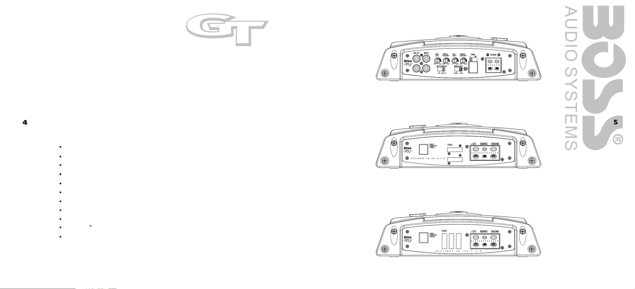
GT1500D and GT2500D Front
CLASS-D MONOBLOCK AMPLIFIER
GT1500D and GT2500D
One Ohm Stable MonoBlock amplifier
MOSFET Power Supply
PWM (Pulse Width Modulation) System
Glass/epoxy Printed Circuit Board
Nickel-plated RCA Input and Bypass Output jacks
Nickel-plated Speaker and Power Terminals
Protection Circuitry Against Thermal, Overload and Short Circuit Faults
Variable Subsonic Filter (15Hz-40Hz, 24dB/octave)
Variable Low Pass Filter (50Hz-150Hz, 24dB/octave)
0/180 Phase Selector
Remote Subwoofer Level Control
GT1500D Rear
GT2500D Rear
Page 4

Installation
Low Level Inputs / Speaker / Power Connections
Important Installation Considerations and Precautions
The design philosophy of this amplifier requires strict adherence to proper installation and
load impedance instructions. The minimum recommended impedance is 2 Ohms.
The fuse rating for the GT1500D is 40 amperes (2 x 20A fuses) and the GT2500D carries a
fuse rating of 75 amperes (3 x 25A fuses). Although sufficient for normal working conditions,
overloading of the amplifier may cause these fuses to blow. Please try to avoid overloading
the amp in this manner.
1
Mount the amplifier so that air flow is not restricted.
2
Mount the amplifier to a solid surface, as these amplifiers are extremely heavy.
3
Take extreme caution when mounting the amplifier, so as not to damage the chassis
with a drill or screwdriver.
4
Run a 4 gauge wire from the battery, using a fuse within 18 (457mm) of the positive
battery terminal. The purpose of this fuse is to protect the battery in the event that
this wire accidentally contacts the chassis ground on its run to the amplifier.
5
Place the fuse holder near the amplifier on the 12V POSITIVE lead.
6
Run a 4 gauge wire (as short as possible) to the closest chassis ground point.
Be sure to remove the paint at the connection to the chassis of the vehicle for a good
electrical connection.
7
Run a 16 gauge (or larger) wire to the remote turn-on lead of the head unit.
Connect the speaker(s) as per the wiring diagrams in this manual.
8
9
Using RCA interconnect cables, connect all line inputs and outputs per the wiring
diagrams which follow if possible, keep the RCA cords away from the 12V power and
Ground wiring.
10
Set the controls as described in the following sections of this manual.
,,
GT1500D and GT2500D
To Inputs of
Satellite Amplifier
Power Connections
From Outputs of
Head Unit
SPEAKER IMPEDANCE
4 - 8 OHMS!
While these amplifiers are designed to operate with a minimum load of 1 Ohm, it is highly
recommended that you design your system to operate with 2 Ohms minimum impedance.
Operating a GT digital amp with a speaker impedance load of under 1 Ohm may
result in poor sound quality and serious damage to the amplifier circuitry. Damage to your
amplifier caused by operating with a load of less than 1 Ohm is not covered under the
warranty for this product.
Distribution Block
Capacitor
NOTE: The amplifier may receive its input signal from a head unit or signal processors subwoofer output.
Page 5

Bridging Two Amplifiers
Electrical Wiring
GT1500D and GT2500D
To Inputs of
Satellite Amplifier
From Outputs of
Head Unit
(BRIDGED SWITCH : MASTER POSITION)
SPEAKER IMPEDANCE
4 - 8 OHMS!
All BOSS series power amplifiers are equipped with easy top access screw
terminals. These terminals are n in order to ensure excellent
ickel-plated
electrical contact and to resist corrosion.
When making electrical connections to the amplifier, please observe the following:
Use at least 8 gauge or heavier wire for power and ground connections.
Wire the amplifier directly to the car battery. Make sure there is circuit protection
(such as a fuse) on the positive power lead, within 18 inches of the battery.
For the ground connection, use the shortest possible wire to a good chassis
ground point.
Wire the Remote connection to the remote turn-on lead of your equalizer or head
unit. In some cases this may be the power antenna lead of the head unit.
Remote Subwoofer Level Control
Your BOSS digital amplifier is equipped with a dashboard mount remote subwoofer
level control. Run the supplied dashboard remote control from the front panel of
your amplifier. By turning the level knob clockwise, you will increase the output
of low frequencies.
Fuses
Fuses protect both the amplifier and the electrical system of your vehicle from
faulty conditions. If you must replace the fuse in your Riot amplifier, use a fuse
of exactly the same type and rating. A different type or rating may result in damage
or cause a fire.
(BRIDGED SWITCH : SLAVE POSITION)
Mounting the Amplifier
Mark the location for the mounting screw holes by positioning the amplifier where
you wish to install it and use a scribe (or one of the mounting screws) inserted in
each mounting hole to mark the mounting surface. If the mounting surface is carpeted,
measure the hole centers and mark with a felt tip pen.
Drill pilot holes in the mounting surface for the mounting screws and insert the mounting
screws into these holes. Tighten them securely.
Note: Before beginning your installation, be sure to take note of any wires, lines or
other devices in your vehicle which may be located behind any mounting surface.
Page 6

Precautions
Before you drill or cut any holes, investigate your car's layout very carefully. Take care
when you work near the gas tank, fuel lines, hydraulic lines and electrical wiring.
Troubleshooting
Before removing your amplifier, refer to the list below and follow the suggested
procedures. Always test the speakers and their wires first.
Do not operate the amplifier when it is not mounted. Attach all audio system components
securely within the automobile to prevent damage, especially in case of an accident.
Do not mount this amplifier so that the wire connections are unprotected or in a pinched
condition, or likely to be damaged by nearby objects.
Before making or breaking power connections in your system, disconnect the vehicle
battery. Confirm that your head unit or other equipment is turned off while connecting
the input jacks and speaker terminals.
If you need to replace the power fuse, replace it only with a fuse identical to that supplied
with the system. Using a fuse of different type or rating may result in damage to your
system which isn't covered by the manufacturer's warranty.
Amplifier will not
power up
Protections LED
comes on when
the amplifier is
powered up
No Output
Check for good ground connection.
Check that Remote Input (turn-on) at amplifier has at least 3 volts DC
present.
Check that there is battery power on the + terminal.
Check all fuses.
Check that Protection LED is not lit. If it is lit, shut off amplifier briefly and
then repower it.
Check for short circuits on speaker leads.
Turn down the volume control on the head unit to prevent overdriving.
Remove speaker leads, and reset the amplifier.
If the Protection LED still comes on, then the amplifier is faulty.
Check that all fuses are OK.
Check that amplifier is properly grounded.
Check that Remote Input (turn-on) at amplifier has at least 3 volts DC
present.
Check that RCA patch cords are plugged into correct inputs.
Check speaker wiring.
Low Output
High hiss in
speakers
Reset Level Control.
Check Crossover Control settings.
Disconnect all RCA inputs to the amplifiers. If the hiss disappears, then
plug in the component driving the amplifier and unplug its inputs. If hiss
disappears, go on until the faulty/noisy component is found.
In order to obtain the best subjective S/N ratio, set the Input Level to the
lowest level possible which still delivers the volume level you desire.
Page 7

Troubleshooting, cont.
High squeal noise
from speakers
Check all RCA interconnects. High squealing noises are almost always caused
by RCA cables with poor grounding. Always use high-quality RCA interconnects
in your audio system.
12
Distorted sound
Amplifier gets
very hot
Engine noise
(static type)
Engine noise
(alternator whine)
Check that the Level control(s) is set to match the signal level of the head unit. Always
begin at the lowest setting.
Check that crossover frequencies have been properly set.
Check for short circuits on the speaker leads.
Check that the minimum speaker impedance for that model is correct.
Check that there is good airflow around the amplifier. In some applications, an external
cooling fan may be required.
Check all RCA interconnects. Engine static noises are almost always caused by RCA
cables with poor grounding. Always use high-quality RCAi interconnects in your
audio system.
Check that there are no shorts between speaker leads or RCA grounds and the vehicle
chassis. Check that the head unit is properly grounded.
 Loading...