

Page 1

Parameter Guide
01
Page 2

Contents
Basic Operation . . . . . . . . . . . . . . . . . . . . . . . . . . . . . . . . . . . . . . . . . 3
Basic Procedure for Eect Editing . . . . . . . . . . . . . . . . . . . . . . . . . 3
Eect Placement . . . . . . . . . . . . . . . . . . . . . . . . . . . . . . . . . . . . . . . . . 3
Using STOMPBOX . . . . . . . . . . . . . . . . . . . . . . . . . . . . . . . . . . . . . . . . . 4
Editing the STOMPBOX . . . . . . . . . . . . . . . . . . . . . . . . . . . . . . . . . . . 4
Reading STOMPBOX Settings into a Patch . . . . . . . . . . . . . . . . . 4
Writing Patch Settings into a STOMPBOX . . . . . . . . . . . . . . . . . . 4
Basic MENU Operations . . . . . . . . . . . . . . . . . . . . . . . . . . . . . . . . . . . 5
Eect . . . . . . . . . . . . . . . . . . . . . . . . . . . . . . . . . . . . . . . . . . . . . . . . . . . . 6
COMPRESSOR . . . . . . . . . . . . . . . . . . . . . . . . . . . . . . . . . . . . . . . . . . . . 6
DISTORTION 1, 2 . . . . . . . . . . . . . . . . . . . . . . . . . . . . . . . . . . . . . . . . . . 6
AIRD PREAMP 1, 2 . . . . . . . . . . . . . . . . . . . . . . . . . . . . . . . . . . . . . . . . 7
NOISE SUPPRESSOR 1, 2. . . . . . . . . . . . . . . . . . . . . . . . . . . . . . . . . . . 8
EQUALIZER 1–4 . . . . . . . . . . . . . . . . . . . . . . . . . . . . . . . . . . . . . . . . . . . 9
DELAY 1–4 . . . . . . . . . . . . . . . . . . . . . . . . . . . . . . . . . . . . . . . . . . . . . . . . 9
MASTER DELAY . . . . . . . . . . . . . . . . . . . . . . . . . . . . . . . . . . . . . . . . . . . 10
CHORUS . . . . . . . . . . . . . . . . . . . . . . . . . . . . . . . . . . . . . . . . . . . . . . . . . . 12
FX1–FX3 . . . . . . . . . . . . . . . . . . . . . . . . . . . . . . . . . . . . . . . . . . . . . . . . . . 13
AC.G SIM (AC. GUITAR SIMULATOR) . . . . . . . . . . . . . . . . . . . . . . . . 13
AC RESO (AC RESONANCE) . . . . . . . . . . . . . . . . . . . . . . . . . . . . . . . 13
AUTO WAH . . . . . . . . . . . . . . . . . . . . . . . . . . . . . . . . . . . . . . . . . . . . . . 14
CHORUS . . . . . . . . . . . . . . . . . . . . . . . . . . . . . . . . . . . . . . . . . . . . . . . . 14
CHO BASS (CHORUS BASS) . . . . . . . . . . . . . . . . . . . . . . . . . . . . . . . 16
C-VIBE (CLASSIC VIBE) . . . . . . . . . . . . . . . . . . . . . . . . . . . . . . . . . . . . 16
COMP (COMPRESSOR) . . . . . . . . . . . . . . . . . . . . . . . . . . . . . . . . . . . . 16
DEFRETR (DEFRETTER) . . . . . . . . . . . . . . . . . . . . . . . . . . . . . . . . . . . 17
DEFRET B (DEFRETTER BASS) . . . . . . . . . . . . . . . . . . . . . . . . . . . . . 17
DIST (DISTORTION) . . . . . . . . . . . . . . . . . . . . . . . . . . . . . . . . . . . . . . . 17
FEEDBAKR (FEEDBACKER) . . . . . . . . . . . . . . . . . . . . . . . . . . . . . . . . 18
FLANGER/FLANGR B (FLANGER B) . . . . . . . . . . . . . . . . . . . . . . . . . 18
HARMONST (HARMONIST) . . . . . . . . . . . . . . . . . . . . . . . . . . . . . . . 19
HUMANIZR (HUMANIZER) . . . . . . . . . . . . . . . . . . . . . . . . . . . . . . . . 20
OCTAVE . . . . . . . . . . . . . . . . . . . . . . . . . . . . . . . . . . . . . . . . . . . . . . . . . 20
OCT BASS (OCTAVE BASS) . . . . . . . . . . . . . . . . . . . . . . . . . . . . . . . . 20
OVERTONE . . . . . . . . . . . . . . . . . . . . . . . . . . . . . . . . . . . . . . . . . . . . . . 20
PAN . . . . . . . . . . . . . . . . . . . . . . . . . . . . . . . . . . . . . . . . . . . . . . . . . . . . . 21
PHASER . . . . . . . . . . . . . . . . . . . . . . . . . . . . . . . . . . . . . . . . . . . . . . . . . 21
PITCH SFT (PITCH SHIFTER) . . . . . . . . . . . . . . . . . . . . . . . . . . . . . . . 22
RING MOD . . . . . . . . . . . . . . . . . . . . . . . . . . . . . . . . . . . . . . . . . . . . . . 22
RO TARY . . . . . . . . . . . . . . . . . . . . . . . . . . . . . . . . . . . . . . . . . . . . . . . . . 23
SITAR SIM. . . . . . . . . . . . . . . . . . . . . . . . . . . . . . . . . . . . . . . . . . . . . . . . 23
SLICER . . . . . . . . . . . . . . . . . . . . . . . . . . . . . . . . . . . . . . . . . . . . . . . . . . 23
SLW GEAR (SLOW GEAR)/
SG BASS (SLOW GEAR BASS)
SND HOLD (SOUND HOLD) . . . . . . . . . . . . . . . . . . . . . . . . . . . . . . . 24
S-BEND . . . . . . . . . . . . . . . . . . . . . . . . . . . . . . . . . . . . . . . . . . . . . . . . . 24
TOUCH WH (TOUCH WAH)/
TW BASS (TOUCH WAH BASS)
TREMOLO . . . . . . . . . . . . . . . . . . . . . . . . . . . . . . . . . . . . . . . . . . . . . . . 24
VIBRATO . . . . . . . . . . . . . . . . . . . . . . . . . . . . . . . . . . . . . . . . . . . . . . . . 25
. . . . . . . . . . . . . . . . . . . . . . . . . . . . . . 23
. . . . . . . . . . . . . . . . . . . . . . . . . . . . . 24
REVERB. . . . . . . . . . . . . . . . . . . . . . . . . . . . . . . . . . . . . . . . . . . . . . . . . . . 25
PEDAL FX . . . . . . . . . . . . . . . . . . . . . . . . . . . . . . . . . . . . . . . . . . . . . . . . . 26
FOOT VOLUME . . . . . . . . . . . . . . . . . . . . . . . . . . . . . . . . . . . . . . . . . . . . 27
DIVIDER 1–3 . . . . . . . . . . . . . . . . . . . . . . . . . . . . . . . . . . . . . . . . . . . . . . 27
MIXER 1–3 . . . . . . . . . . . . . . . . . . . . . . . . . . . . . . . . . . . . . . . . . . . . . . . . 28
SEND/RETURN 1, 2 . . . . . . . . . . . . . . . . . . . . . . . . . . . . . . . . . . . . . . . . 28
OUTPUT SP.SIMULATOR L, OUTPUT SP.SIMULATOR R, SUB
OUT SP.SIMULATOR L, SUB OUT SP.SIMULATOR R
MASTER . . . . . . . . . . . . . . . . . . . . . . . . . . . . . . . . . . . . . . . . . . . . . . . . . . 30
. . . . . . . . . . . 29
MENU. . . . . . . . . . . . . . . . . . . . . . . . . . . . . . . . . . . . . . . . . . . . . . . . . . . . 32
CONTROL MODE . . . . . . . . . . . . . . . . . . . . . . . . . . . . . . . . . . . . . . . . . . 32
CONTROL ASSIGN . . . . . . . . . . . . . . . . . . . . . . . . . . . . . . . . . . . . . . . . 32
CONTROL FUNCTION . . . . . . . . . . . . . . . . . . . . . . . . . . . . . . . . . . . . 32
ASSIGN SETTING . . . . . . . . . . . . . . . . . . . . . . . . . . . . . . . . . . . . . . . . . 34
Virtual Expression Pedal (Internal Pedal / Wave Pedal) . . . . . . 42
INPUT (Input Level) . . . . . . . . . . . . . . . . . . . . . . . . . . . . . . . . . . . . . . 42
INPUT SENS (Input Sens) . . . . . . . . . . . . . . . . . . . . . . . . . . . . . . . . . 42
PATCH MIDI . . . . . . . . . . . . . . . . . . . . . . . . . . . . . . . . . . . . . . . . . . . . . . 43
LED COLOR . . . . . . . . . . . . . . . . . . . . . . . . . . . . . . . . . . . . . . . . . . . . . . 43
TEMPO HOLD . . . . . . . . . . . . . . . . . . . . . . . . . . . . . . . . . . . . . . . . . . . . 43
IN/OUT SETTING . . . . . . . . . . . . . . . . . . . . . . . . . . . . . . . . . . . . . . . . . . 44
INPUT . . . . . . . . . . . . . . . . . . . . . . . . . . . . . . . . . . . . . . . . . . . . . . . . . . . 44
OUTPUT, SUB OUT . . . . . . . . . . . . . . . . . . . . . . . . . . . . . . . . . . . . . . . 44
TOTAL . . . . . . . . . . . . . . . . . . . . . . . . . . . . . . . . . . . . . . . . . . . . . . . . . . . 45
USB-Related Settings . . . . . . . . . . . . . . . . . . . . . . . . . . . . . . . . . . . . . 46
PLAY OPTION . . . . . . . . . . . . . . . . . . . . . . . . . . . . . . . . . . . . . . . . . . . . . 47
MIDI . . . . . . . . . . . . . . . . . . . . . . . . . . . . . . . . . . . . . . . . . . . . . . . . . . . . . . 47
MIDI SETTING. . . . . . . . . . . . . . . . . . . . . . . . . . . . . . . . . . . . . . . . . . . . 47
PROGRAM MAP BANK1–BANK4 . . . . . . . . . . . . . . . . . . . . . . . . . . . 48
BULK DUMP . . . . . . . . . . . . . . . . . . . . . . . . . . . . . . . . . . . . . . . . . . . . . 48
HARDWARE SETTING . . . . . . . . . . . . . . . . . . . . . . . . . . . . . . . . . . . . . 49
KNOB . . . . . . . . . . . . . . . . . . . . . . . . . . . . . . . . . . . . . . . . . . . . . . . . . . . 49
AMP CONTROL . . . . . . . . . . . . . . . . . . . . . . . . . . . . . . . . . . . . . . . . . . 54
EXP HOLD . . . . . . . . . . . . . . . . . . . . . . . . . . . . . . . . . . . . . . . . . . . . . . . 54
GROUND LIFT . . . . . . . . . . . . . . . . . . . . . . . . . . . . . . . . . . . . . . . . . . . 54
OTHER . . . . . . . . . . . . . . . . . . . . . . . . . . . . . . . . . . . . . . . . . . . . . . . . . . 54
FACTORY RESET . . . . . . . . . . . . . . . . . . . . . . . . . . . . . . . . . . . . . . . . . . 55
TUNER . . . . . . . . . . . . . . . . . . . . . . . . . . . . . . . . . . . . . . . . . . . . . . . . . . . 55
METRONOME . . . . . . . . . . . . . . . . . . . . . . . . . . . . . . . . . . . . . . . . . . . . . 55
Saving a Sound (WRITE) . . . . . . . . . . . . . . . . . . . . . . . . . . . . . . . . 56
Saving a Patch (PATCH WRITE) . . . . . . . . . . . . . . . . . . . . . . . . . . . . . 56
Exchanging Patches (PATCH EXCHANGE) . . . . . . . . . . . . . . . . . . . 56
Initializing Patches (PATCH INITIALIZE) . . . . . . . . . . . . . . . . . . . . 57
Inserting a Patch (PATCH INSERT) . . . . . . . . . . . . . . . . . . . . . . . . . . 57
MEMO
This eect sound is mono.
5
5
This eect sound is output with two channels.
5
These eects take a mono input and output it on two channels.
* Company names and product names appearing in this document are registered trademarks or trademarks of their respective owners.
Copyright © 2020 ROLAND CORPORATION
2
Page 3
Basic Operation
Basic Procedure for Eect Editing
The edit screens show the block conguration (eect chain) of all
eects provided by the GT-1000CORE, as well as the output and
send/return. You can edit from this eect chain display by selecting
the block that you want to edit.
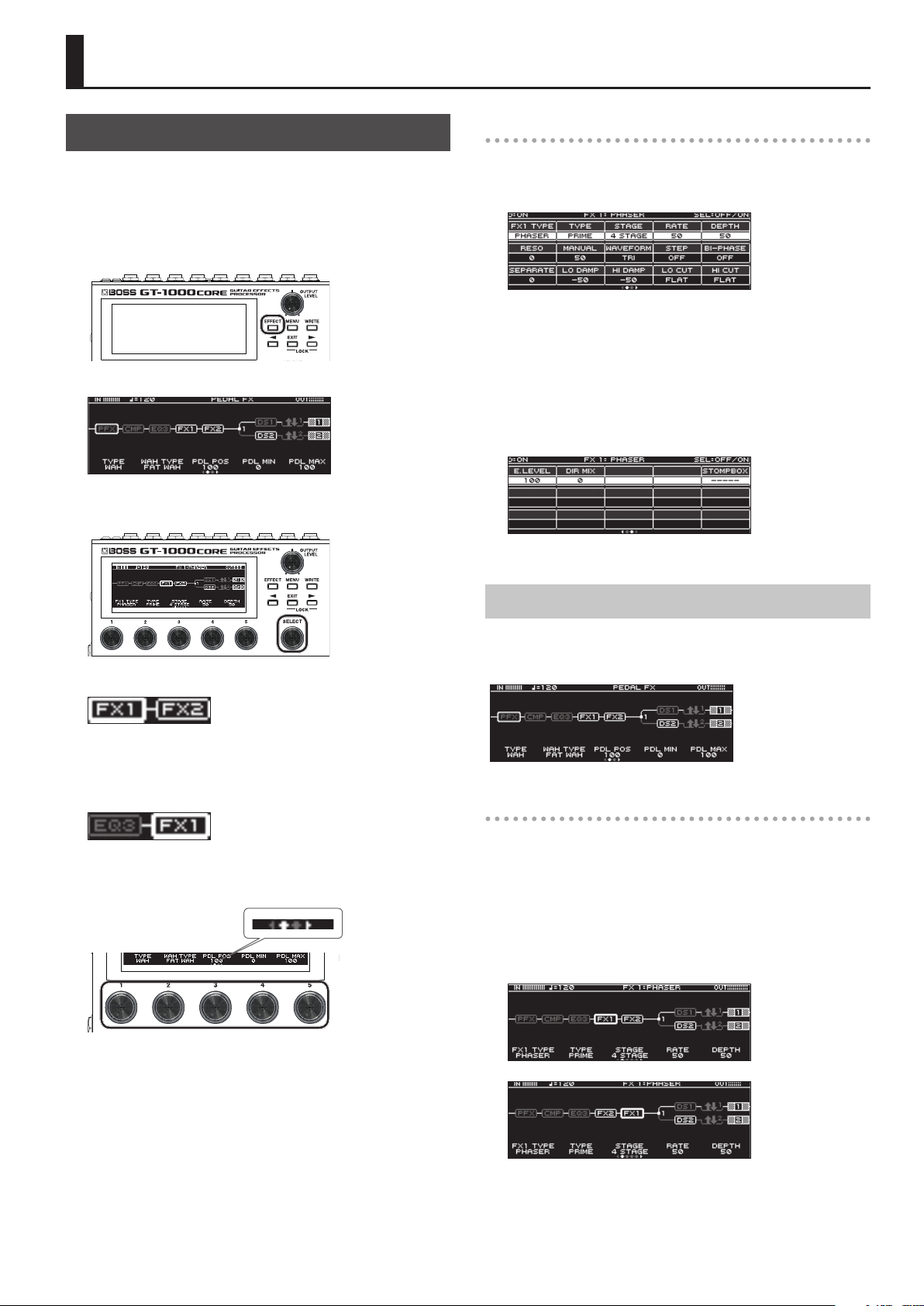
1. Press the [EFFECT] button.
The edit screen (eect chain) appears.
2. Turn knob [6] to select the block that you want to
edit.
Editing while viewing all parameters
From the edit screen, you can long-press knob [SELECT] to see a list
of all parameters of the selected block. You can edit the parameters
from this list.
1. Turn the [SELECT] knob to select the item that you
want to set.
Turning the knob will move the selected item vertically.
2. Turn knobs [1]–[6] to edit the value of the
parameters shown in the screen.
Use the PAGE [K] [J] buttons to switch between lists of parameters.
The selected block is enclosed by a thick frame.
* By pressing knob [SELECT] you can turn the selected eect on/o.
Eects that are o are shown in gray. When the eect is turned on,
it is shown in white.
O On
3. Use knobs [1]–[5] to adjust the parameters that are
shown below the screen.
Eect Placement
By moving blocks such as eects, output, and send/return, you can
freely change the order in which the eects are placed, or arrange
them in parallel.
Changing the placement of eects etc.
1. Press the [EFFECT] button.
The eect chain is shown.
2. Use knob [SELECT] to select the block that you
want to move.
3. While pressing knob [SELECT], turn it left or right.
The selected block moves left or right.
Use the PAGE [K] [J] buttons to switch between the parameters
that you want to edit. The current page is indicated in the lower
center of the screen.
* To change a value in larger steps, turn a knob while pressing it.
* The number of parameters and pages diers depending on the
eect.
3
Page 4
Basic Operation
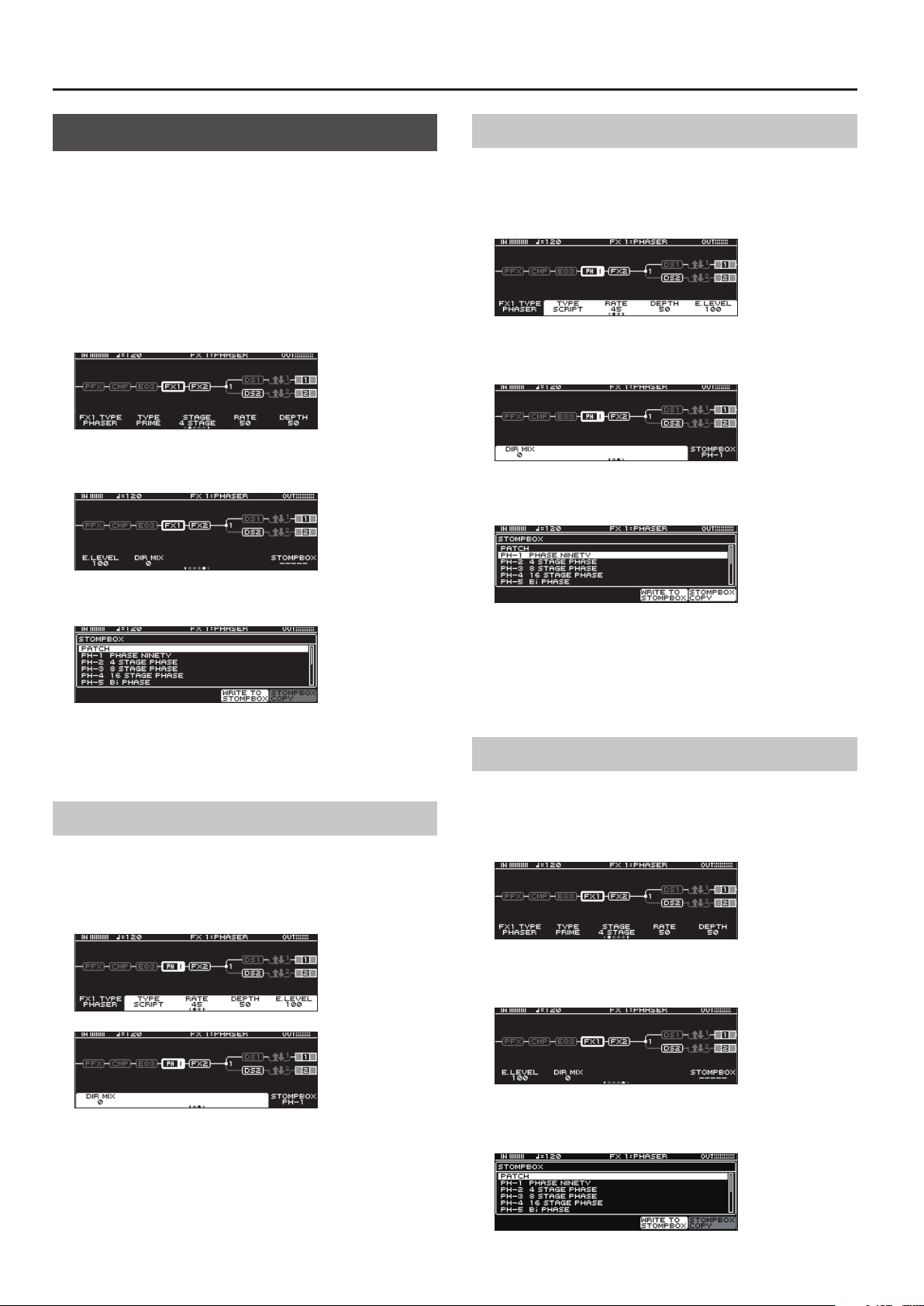
Using STOMPBOX
Your preferred settings for each eect can be saved as a “STOMPBOX.”
You can select these saved settings and use them to create your
sound just as though you were connecting compact pedal eects.
The STOMPBOX data is common to all patches; this means that all
patches using the same STOMPBOX can be edited simultaneously.
1. Press the [EFFECT] button.
2. Use the [SELECT] knob to choose the eect you’re
going to edit.
3. Use the PAGE [
page.
K
] [J] buttons to move to the last
Reading STOMPBOX Settings into a Patch
1. Press the [EFFECT] button.
2. Use the [SELECT] knob to choose the eect you’re
going to edit.
3. Use the PAGE [
page.
4. Press the [5] knob.
The STOMPBOX select window appears.
K
] [J] buttons to move to the last
4. Press the [5] knob.
The STOMPBOX select window appears.
5. Turn knob [SELECT] to select the STOMPBOX type.
6. Press the [SELECT] knob.
Editing the STOMPBOX
1. Turn knobs [1]–[5] to edit the parameter value that
are shown in the screen.
Use the PAGE [K] [J] buttons to switch between lists of
parameters.
5. Turn knob [SELECT] to select the STOMPBOX type.
6. Press the [5] (STOMPBOX COPY) knob.
The contents of the STOMPBOX are recalled into the patch.
You can edit the patch without modifying the contents of the
STOMPBOX.
Writing Patch Settings into a STOMPBOX
1. Press the [EFFECT] button.
2. Use the [SELECT] knob to choose the eect you’re
going to save.
3. Use the PAGE [
page.
K
] [J] buttons to move to the last
4. Press the [5] knob.
The STOMPBOX select window appears.
4
Page 5

5. Press the [4] (WRITE TO STOMPBOX) knob.
6. Turn knob [1] to select the writing-destination
STOMPBOX.
7. Use knobs [3]–[5] and [SELECT] knob to name the
STOMPBOX.
You can turn the [SELECT] knob to move the cursor within the
name.
Reference
For details on naming the STOMPBOX, refer to “Editing a name”
(p. 56).
Basic MENU Operations
Here you can make settings that are common to the entire GT-1000CORE
(system parameters).
Basic Operation
1. Press the [MENU] button.
* You can use the PAGE [K] [J] buttons to see additional items.
2. Press a knob [1]–[5] to select the item that you want
to edit.
A sub-menu appears.
3. Once again press a knob [1]–[5] to select the item
that you want to edit.
4. Use knobs [1]–[5] and [SELECT] knob to select
parameters or edit the values.
5
Page 6
Eect
* Company names and product names appearing in this document are registered
trademarks or trademarks of their respective owners.
* In this manual, company names and product names of the respective owners
are used because it is the most practical way of describing the sounds that are
emulated using DSP technology.
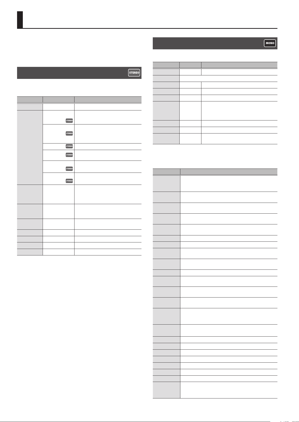
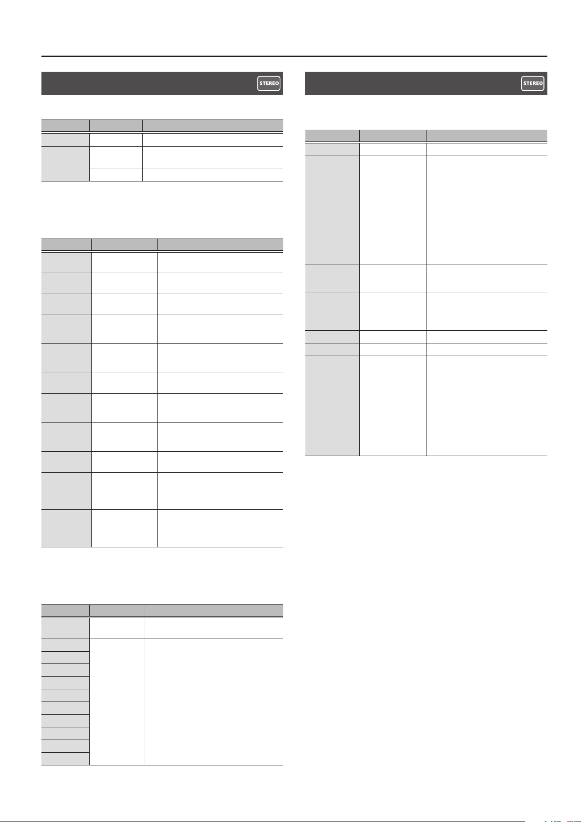
COMPRESSOR
This is an eect that produces a long sustain by evening out the
volume level of the input signal.
Parameter Value Explanation
ON/OFF OFF, ON Turns this eect on/o.
BOSS CMP
(BOSS COMP)
X-COMP
TYPE
THRESHLD *1 0–100
SUSTAIN *2 0–100
ATTAC K 0–100
LEVEL 0–100 Adjusts the volume.
TONE -50–+50 Adjusts the tone.
RATIO 1:1–INF:1 Selects the compression ratio.
DIR MIX 0–100 Adjusts the volume of the direct sound.
*1 Setting available when TYPE is set to X-BASS.
*2 Not shown if TYPE is set to X-BASS.
D-COMP This models a MXR DynaComp.
ORANGE
STEREO
X-BASS
This models a BOSS CS-3.
This uses MDP (Multi-Dimensional
Processing) to obtain a consistently natural
playing feel and sound that responds to the
pitch range and dynamics of your phrase.
This is modeled on the sound of the Dan
Armstrong ORANGE SQUEEZER.
This selects a stereo compressor.
This is a compressor for bass that uses MDP
(Multi-Dimensional Processing).
Adjust this as appropriate for the input
signal. When the input signal level exceeds
this threshold level, compression will be
applied.
Adjusts the range (time) over which lowlevel signals are boosted. Larger values will
result in longer sustain.
Adjusts the strength of the attack when
picking.
DISTORTION 1, 2
This eect distorts the sound to create long sustain.
Parameter Value Explanation
ON/OFF OFF, ON Turns this eect on/o.
TYPE Refer to “DISTORTION 1, 2 TYPE” (p. 6)
DRIVE 0–120 Adjusts the depth of distortion.
TONE -50–+50 Adjusts the tone.
LEVEL 0–100 Adjusts the volume of the eect sound.
Adjusts the tone for the low frequency range.
BOTTOM -50–+50
DIR MIX 0–100 Adjusts the volume of the direct sound.
SOLO SW OFF, ON The tone to one suitable for solos.
SOLO LVL
(SOLO LEVEL)
0–100
DISTORTION 1, 2 TYPE
This is a list of distortion types that can be selected for DISTORTION 1, 2
Type Explanation
MID
(MID BOOST)
CLEAN
(CLEAN BOOST)
TREBLE
(TREBLE BOOST)
CRUNCH
NATURAL
(NATURAL OD)
WARM OD This is a warm overdrive.
FAT DS A distortion sound with thick distortion.
LEAD DS
METAL DS
OCT FUZZ A fuzz sound with rich harmonic content.
A-DIST
X-OD
X-DIST
BLUES OD
OD-1
T-SCREAM This models an Ibanez TS-808.
TURBO OD This is the high-gain overdrive sound of the BOSS OD-2.
DIST This gives a basic, traditional distortion sound.
CENTA OD This models a KLON CENTAUR.
RAT This models a Proco RAT.
GUV DS This models a Marshall GUV’ NOR.
DIST+ This models the sound of the MXR DISTORTION+.
MTL ZONE
(METAL ZONE)
This is a booster with unique characteristics in the midrange.
Making the connection before the AIRD PREAMP produces
sound suitable for solos.
This not only functions as a booster, but also produces a clean
tone that has punch even when used alone.
This is a booster that has bright characteristics.
A lustrous crunch sound with an added element of amp
distortion.
This is an overdrive sound that provides distortion with a natural
feeling.
Produces a distortion sound with both the smoothness of an
overdrive along with a deep distortion.
This is a distortion sound that is ideal for performances of heavy
ris.
This uses MDP technology to obtain ideal distortion in all ranges
of the guitar, from low to high.
This is an overdrive that uses MDP to obtain the distortion that’s
most appropriate in each pitch range.
This is a distortion that uses MDP to obtain the distortion that’s
most appropriate in each pitch range.
This is a crunch sound of the BOSS BD-2.
This produces distortion that faithfully reproduces the nuances
of picking.
This models the sound of the BOSS OD-1.
This produces sweet, mild distortion.
This models the sound of the BOSS MT-2.
It produces a wide range of metal sounds, from old style to slash
metal.
Turning this to the left (counterclockwise)
produces a sound with the low end cut; turning it
to the right boosts the low end in the sound.
Adjusts the volume level when the SOLO SW is
ON.
6
Page 7
Type Explanation
HM-2
MTL CORE
(METAL CORE)
60S FUZZ
MUFF FUZ
(MUFF FUZZ)
BASS OD Overdrive tuned especially for use with basses.
BASS DS Distortion tuned especially for use with basses.
BASS MT Wild, radical distortion sound.
BASS FUZZ Fuzz tuned especially for use with basses.
HI BAND
X-BASS
BASS DRV This models a TECH21 SANSAMP BASS DRIVER DI.
BASS DI This models a MXR Bass D.I.+.
* Company names and product names appearing in this document are registered
trademarks or trademarks of their respective owners.
* In this manual, company names and product names of the respective owners
are used because it is the most practical way of describing the sounds that are
emulated using DSP technology.
This models the sound of the BOSS HM-2.
It produces distinctive cranked-up distortion sound with
compression.
This is the sound of the BOSS ML-2 which is ideal for high speed
metal ris.
This models a FUZZFACE.
It produces a fat fuzz sound.
This models an Electro-Harmonix Big Mu π.
With this eect, distortion is applied only to the high frequency
sounds, and not to the sounds in the low frequency range.
This eect uses MDP to provide ideal distortion in all pitch
ranges of the bass, from low to high.
Eect
AIRD PREAMP 1, 2
This is an amp that uses BOSS’s proprietary cutting-edge AIRD
(Augmented Impulse Response Dynamics) technology to simulate
every detail of a guitar amp as a unied instrument, including the
response and operation of the guitar amp’s circuit and the interactions
between all parts that aect the sound.
Parameter Value Explanation
ON/OFF OFF, ON Turns this eect on/o.
TYPE Refer to “AIRD PREAMP TYPE List” (p. 8)
GAIN 0–120 Adjusts the distortion of the amp.
SAG -10–+10
RESO
(RESONANCE)
LEVEL 0–100
BASS 0–100 Adjusts the tone for the low frequency range.
MIDDLE 0–100 Adjusts the tone for the middle frequency range.
TREBLE 0–100 Adjusts the tone for the high frequency range.
PRESENCE 0–100 Adjusts the tone for the ultra high frequency range.
BRIGHT OFF, ON
GAIN SW
SOLO SW OFF, ON The tone to one suitable for solos.
SOLO LVL
(SOLO LEVEL)
-10–+10
LOW,
MIDDLE,
HIGH
0–100 Adjusts the volume level when the SOLO SW is ON.
Adjusts the amount by which compression
changes in response to the power amp.
Adjusts the amount by which dynamics is aected
by the interaction between the power amp and
the speaker transformer.
Adjusts the volume of the entire preamp.
* Be careful not to raise the Level setting too high.
Turns the bright setting on/o.
* The BRIGHT setting is available only when
certain AIRD PREAMP TYPE settings are selected.
Provides for selection from three levels of
distortion: LOW, MIDDLE, and HIGH. Distortion will
successively increase for settings of LOW, MIDDLE
and HIGH.
* The sound of each Type is created on the basis
that the Gain is set to MIDDLE. So, normally set
it to MIDDLE.
7
Page 8

Eect
AIRD PREAMP TYPE List
Category Type Explanation
TRNSPRNT
(TRANSPARENT)
NATURAL
BOUTIQUE
SUPREME
TYPE
(ADVANCED AMP)
MAXIMUM
JUGGERNT
(JUGGERNAUT)
X-CRUNCH
X-HI GAIN
X-MODDED
JC-120
TWIN
(TWIN COMBO)
DELUXE
(DELUXE COMBO)
TWEED
(TWEED COMBO)
DIAMOND
(DIAMOND AMP)
BRIT STK
TYPE (CLASSICS)
TYPE
(ADVANCED AMP)
TYPE (CLASSICS) CONCERT This models the Ampeg SVT.
(BRIT STACK)
RECTI STK
(RECTI STACK)
MAT CH
(MATCH COMBO)
BG COMBO
ORNG STK
(ORNG STACK)
BGNR UB
(BGNR UB METAL)
NATRL BS
(NATURAL BASS)
X-DRV BS
(X-DRIVE BASS)
An amp with a broad frequency
range and an extremely at response.
Good for acoustic guitar.
An unembellished, clean sound that
minimizes the amp’s idiosyncrasies,
such as its trebly character and
boomy low end.
Crunch sound that allows the
nuances of your picking to be
expressed even more faithfully than
on conventional combo amps.
Great-feeling crunch sound that
responds to the nuances of your
picking while taking advantage of
the distinctive character of a 4x12”
speaker cabinet.
An amp that delivers the distinctively
great response and tone of a vintage
Marshall, while making it even higher
gain.
A large stack sound that has been
tweaked extensively in the pursuit of
the ultimate metal sound.
Crunch sound that uses MDP to
deliver a crisp tone from all strings.
High-gain sound that uses MDP to
obtain high-gain sound with a wide
range and a great-feeling sense of
separation.
Core sound that uses MDP to
preserve the denition of the sound
even with extreme gain.
This models the sound of the Roland
JC-120.
This models a Fender Twin Reverb.
This models a Fender Deluxe Reverb.
This models a Fender Bassman 4 x
10” Combo.
This models a VOX AC30.
This models a Marshall 1959.
Models the sound of the Channel 2
MODERN Mode on the MESA/Boogie
DUAL Rectier.
This models the sound input to left
input on a Matchless D/C-30.
This models the sound of the MESA/
Boogie combo amp.
This models the dirty channel of an
ORANGE ROCKERVERB.
This models the sound that models
the high-gain channel of a Bogner
Uberschall.
Uncolored clean sound for bass.
High-gain sound for bass, using MDP
to provide wide range and a goodsounding sense of separation.
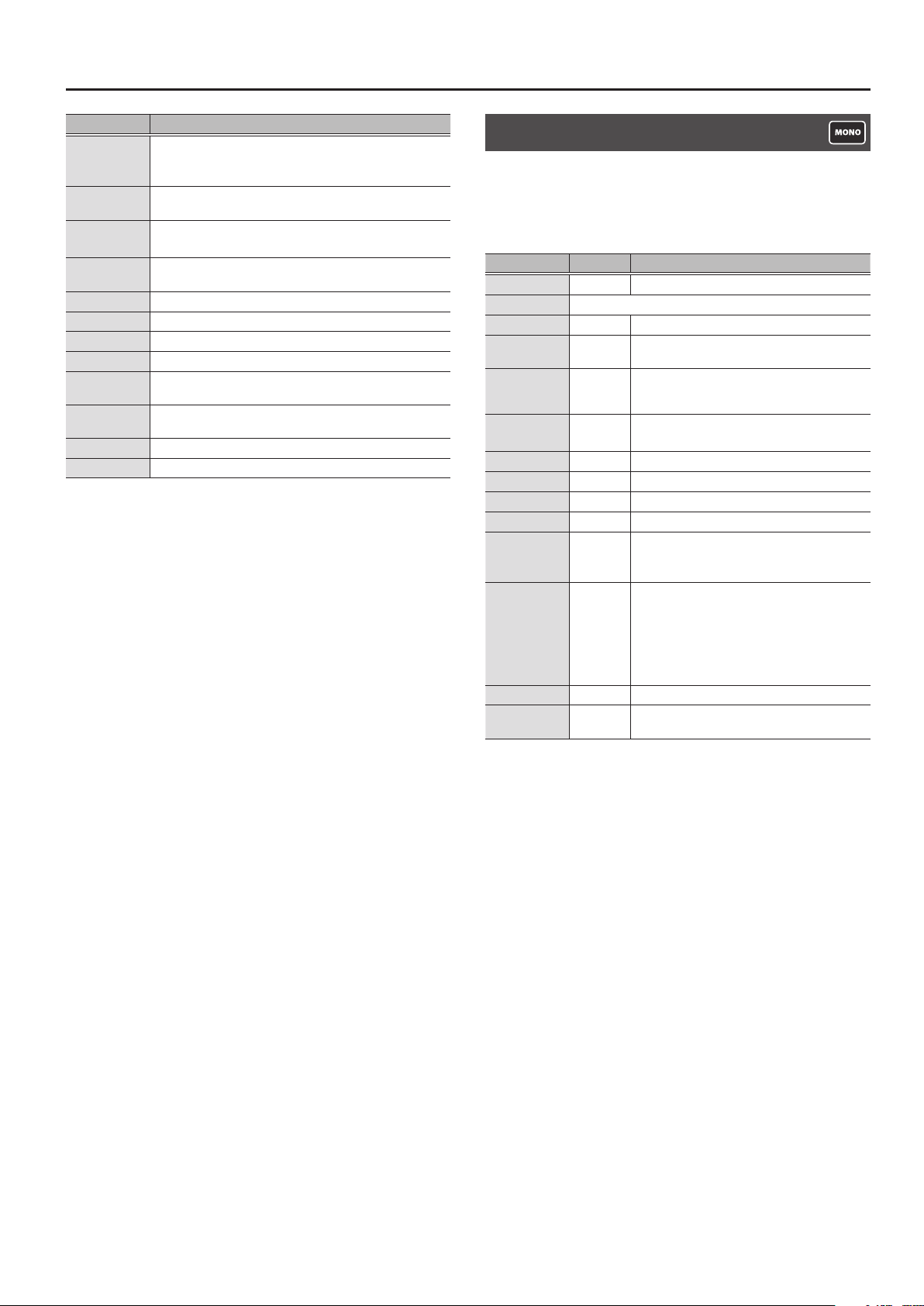
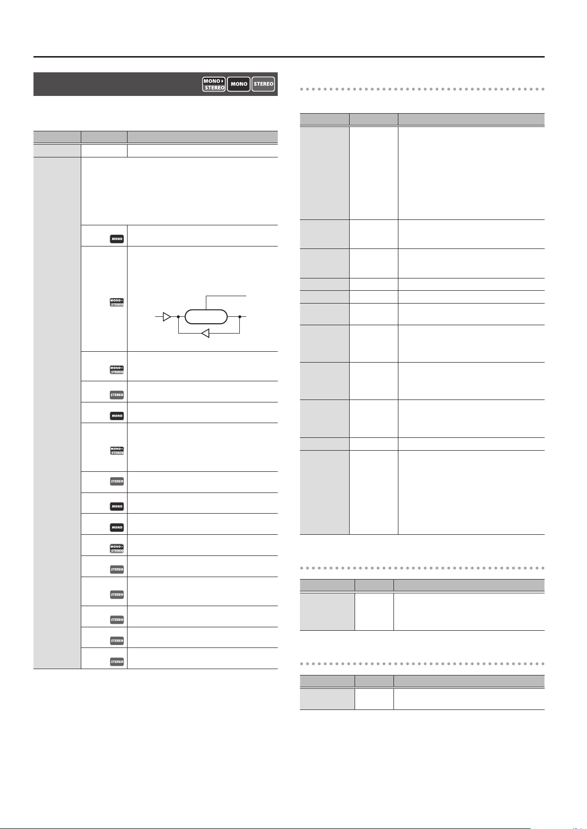
NOISE SUPPRESSOR 1, 2
This eect reduces the noise and hum picked up by guitar pickups.
Since it suppresses the noise in synchronization with the envelope
of the guitar sound (the way in which the guitar sound decays over
time), it has very little eect on the guitar sound, and does not harm
the natural character of the sound.
Parameter Value Explanation
ON/OFF OFF, ON Turns this eect on/o.
Adjust this parameter as appropriate for the
volume of the noise. If the noise level is high, a
higher setting is appropriate. If the noise level is
THRESHLD
(THRESHOLD)
RELEASE 0–100
DETECT
0–100
This controls the noise suppressor based on the volume level for
the point specied in Detect.
INPUT
NS INPUT
FV OUT
low, a lower setting is appropriate. Adjust this value
until the decay of the guitar sound is as natural as
possible.
* High settings for the threshold parameter may
result in there being no sound when you play
with your guitar volume turned down.
Adjusts the time from when the noise suppressor
begins to function until the noise level reaches “0.”
Input volume from input jack.
* Ordinarily, DETECT should be set to “INPUT.”
Noise suppressor input volume.
* When connected as illustrated below, and you
want to prevent a spatial-type eects sound
(such as a delay sound) from being eradicated
by the NS, you should set DETECT to “NS INPUT.”
NSDLY
(Spatial-type eect)
Volume after passing through Foot Volume.
* If you want to use FV (Foot Volume) in place
of the guitar’s volume control, you need to set
DETECT to “FV OUT.”
INPUT
Foot Volume
NSFV
* Company names and product names appearing in this document are registered
trademarks or trademarks of their respective owners.
* In this manual, company names and product names of the respective owners
are used because it is the most practical way of describing the sounds that are
emulated using DSP technology.
8
Page 9
Eect
EQUALIZER 1–4
Adjusts the tone.
Parameter Value Explanation
ON/OFF OFF, ON Turns this eect on/o.
PARAMTRC
TYPE
(PARAMETRIC)
GRAPHIC You can adjust the tone character in ten bands.
PARAMETRIC
Adjusts the tonal quality. You can adjust the tone character in four
bands.
Parameter Value Explanation
LO GAIN -20–+20dB
HI GAIN -20–+20dB
LEVEL -20–+20dB
LM FREQ 20.0Hz–16.0kHz
LM Q 0.5–16
LM GAIN -20–+20dB
HM FREQ 20.0Hz–16.0kHz
HM Q 0.5–16
HM GAIN -20–+20dB
LO CUT
HI CUT
FLAT,
20.0Hz–20.0kHz
20.0Hz–20.0kHz
FLAT
You can adjust the tone character in four bands.
Adjusts the tone for the low frequency
range.
Adjusts the tone for the high frequency
range.
Adjusts the overall volume level of the
equalizer.
Species the center of the frequency
range that will be adjusted by the LM
GAIN.
Adjusts the width of the area aected by
the EQ centered at the LM FREQ. Higher
values will narrow the area.
Adjusts the low-middle frequency range
tone.
Species the center of the frequency
range that will be adjusted by the HM
GAIN.
Adjusts the width of the area aected by
the EQ centered at the HM FREQ. Higher
values will narrow the area.
Adjusts the low-middle frequency range
tone.
This sets the frequency at which the low
cut lter begins to take eect. When FLAT
is selected, the low cut lter will have no
eect.
This sets the frequency at which the high
cut lter begins to take eect. When FLAT
is selected, the high cut lter will have
no eect.
DELAY 1–4
This is a delay with a maximum delay time of 2,000 ms. This eect is a
useful way of adding depth to the sound.
Parameter Value Explanation
ON/OFF OFF, ON Turns this eect on/o.
Adjusts the delay time.
* When set to BPM, the value of each
parameter will be set according
to the value of the “MASTER BPM”
TIME
FEEDBACK 0–100
HI CUT
E.LEVEL 0–120 Adjusts the volume of the delay sound.
D.LEVEL 0–100 Adjusts the volume of the direct sound.
BPM 40–250
1ms–2000ms,
Œ
BPM `–
20.0Hz–20.0kHz
FLAT
specied for each patch. This makes
it easier to achieve eect sound
settings that match the tempo of
the song.
* If, due to the tempo, the time is
longer than the range of allowable
settings, it is then synchronized to a
period either 1/2 or 1/4 of that time.
Adjusts the volume that is returned to
the input. Higher settings will result in
more delay repeats.
This sets the frequency at which the
high cut lter begins to take eect.
When FLAT is selected, the high cut lter
will have no eect.
Adjusts the BPM value for each patch.
* BPM (beats per minute) indicates the
number of quarter note beats that
occur each minute
* When you have an external MIDI
device connected, the MASTER BPM
synchronizes to the external MIDI
devices tempo, making it impossible
to set the MASTER BPM. To enable
setting of the MASTER BPM, set “SYNC
CLOCK” (p. 47) to “INTERNAL.”
GRAPHIC
Adjusts the tonal quality. You can adjust the tone character in ten
bands.
Parameter Value Explanation
LEVEL -20–+20dB
31.5Hz
63Hz
125Hz
250 Hz
500 Hz
1 kHz
2 kHz
4 kHz
8 kHz
16 kHz
-20–+20dB Adjust the volume of each frequency band.
Adjusts the overall volume level of the
equalizer.
9
Page 10
Eect
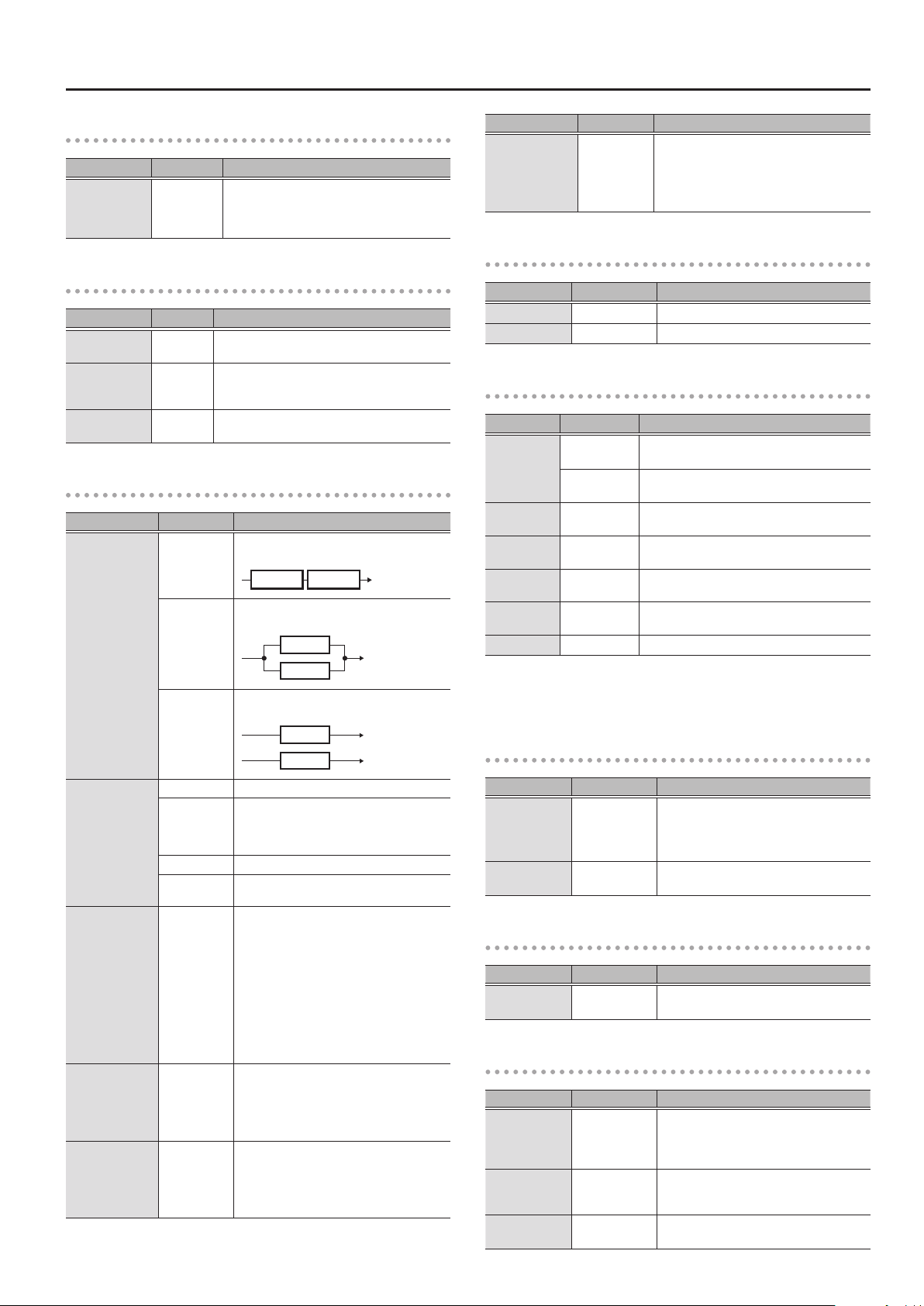
MASTER DELAY
This produces a variety of delay sounds ranging from simple eects to
richly idiosyncratic sounds.
Parameter Value Explanation
ON/OFF OFF, ON Turns this eect on/o.
This selects which type of delay.
* If you switch patches with the Type set to DUAL and then begin
to play immediately after the patches change, you may be
unable to attain the intended eect in the rst portion of what
you perform.
* The stereo eect is cancelled if a mono eect or AIRD PREAMP
is connected after a stereo delay eect.
TYPE
MONO
PAN
STEREO 1
STEREO2
ANALOG This gives a mild analog delay sound. The delay
ANALG ST
TAPE
REVERSE This produces an eect where the sound is played
SHIMMER
DUAL A delay comprising two dierent delays
WARP
This is a simple mono delay.
This delay is specically for stereo output. This
allows you to obtain the tap delay eect that
divides the delay time, then deliver them to L and
R channels.
TAP TIME
EFFECT LEVEL
INPUT
The direct sound is output from the left channel,
and the eect sound is output from the right
channel.
This is a stereo-in/out delay.
time can be set within the range of 12 to 1,200 ms.
This gives a mild analog delay sound. The delay
time can be set within the range of 12 to 1,200 ms.
The direct sound is output from the left channel,
and the eect sound is output from the right
channel.
Provides the characteristic wavering sound of the
tape echo.
back in reverse.
Delay with pitch-shifted sound mixed in.
connected either in series or in parallel.
Produces a dream-like sound.
DELAY
FEEDBACK
OUTPUT R
TIME
OUTPUT L
COMMON
* The COMMON parameters are not shown if TYPE is set to TWIST.
Parameter Value Explanation
Adjusts the delay time.
* When set to BPM, the value of each parameter
will be set according to the value of the
TIME
FEEDBACK 0–100
HI CUT
E.LEVEL 0–120 Adjusts the volume of the delay sound.
MOD RATE 0–100 Adjusts the modulation rate of the delay sound.
MOD DEPT
(MOD DEPTH)
DUCK SENS
(DUCK SENS)
DUCK PRE
(DUCK PRE DEPTH)
DUCK PST
(DUCK POST DEPTH)
D.LEVEL 0–100 Adjusts the volume of the direct sound.
BPM 40–250
1ms–2000ms,
Œ
BPM `–
20.0Hz–
20.0kHz
FLAT
0–100
0–100
0–100
0–100
“MASTER BPM” specied for each patch.
This makes it easier to achieve eect sound
settings that match the tempo of the song.
* If, due to the tempo, the time is longer than
the range of allowable settings, it is then
synchronized to a period either 1/2 or 1/4 of
that time.
This sets the amount of delay sound returned
to the input. A higher value will increase the
number of the delay repeats.
This sets the frequency at which the high cut
lter begins to take eect. When FLAT is selected,
the high cut lter will have no eect.
Adjusts the modulation depth of the delay
sound.
Adjusts the sensitivity at which the volume is
automatically adjusted according to the input.
Higher values allow the adjustment to occur in
response to lower volumes.
The volume being “input” to the delay is
automatically reduced when the input sound is
loud. The amount of reduction increases as this
setting approaches 100.
The volume being “output” to the delay is
automatically reduced when the input sound is
loud. The amount of reduction increases as this
setting approaches 100.
Adjusts the BPM value for each patch.
* BPM (beats per minute) indicates the number
of quarter note beats that occur each minute
* When you have an external MIDI device
connected, the MASTER BPM synchronizes to
the external MIDI devices tempo, making it
impossible to set the MASTER BPM. To enable
setting of the MASTER BPM, set “SYNC CLOCK”
(p. 47) to “INTERNAL.”
PAN
TWIST
SPACE EC
ECHO PX
BIN ECHO
* Company names and product names appearing in this document are registered
trademarks or trademarks of their respective owners.
* In this manual, company names and product names of the respective owners
are used because it is the most practical way of describing the sounds that are
emulated using DSP technology.
Produces an aggressive sense of rotation. Using
this in conjunction with distortion will produce an
even wilder sense of rotation.
This models the sound of the Roland RE-201.
This models the sound of the Maestro Echoplex.
This models the sound of the Binson Echorec2.
10
Parameter Value Explanation
Adjusts the delay time of the right channel delay.
TAP TIME 0–100%
This setting adjusts the R channel delay time
relative to the L channel delay time (considered
as 100%).
REVERSE
Parameter Value Explanation
AUTO TRIG OFF, ON
When this is on, the start position for reverse
playback is adjusted automatically.
Page 11
Eect
TAPE
Parameter Value Explanation
Selects the combination playback heads.
Playback heads 2/3 provide delay times that are
two times or three times as long as playback
head 1.
HEAD
1, 1+2, 1+3,
2+3, 1+2+3
SHIMMER
Parameter Value Explanation
PITCH -24–+24
PITCH BL 0–100
PITCH FB 0–100
Lets you freely specify the amount of pitch shift
for the delay.
Adjusts the balance between the pitch-shifted
sound that is input to the delay and the direct
sound.
Adjusts the amount of feedback for the delay that
is applied to the direct sound.
DUAL
Parameter Value Explanation
This is a delay comprising two dierent delays
connected in series.
D1 D2
This is a delay comprising two delays
connected in parallel.
This delay lets you specify the L and R
channels independently.
This delay is specically for stereo output. This
allows you to obtain the tap delay eect that
divides the delay time, then deliver them to L
and R channels.
This setting provides the characteristic
wavering sound of the tape echo.
Adjusts the delay time.
* When set to BPM, the value of each
parameter will be set according to the
value of the “MASTER BPM” specied for
each patch. This makes it easier to achieve
Œ
eect sound settings that match the
tempo of the song.
* If, due to the tempo, the time is longer
than the range of allowable settings, it is
then synchronized to a period either 1/2 or
1/4 of that time.
Adjusts the amount of feedback of the DELAY
1 (or DELAY 2). A higher value will increase the
number of the delay repeats.
This sets the frequency at which the high
cut lter begins to take eect. When FLAT is
selected, the high cut lter will have no eect.
MODE
1:TYPE
(D1 TYPE)
2:TYPE
(D2 TYPE)
1:TIME
(D1 TIME)
2:TIME
(D2 TIME)
1:FEEDBK
(D1 FEEDBACK)
2:FEEDBK
(D2 FEEDBACK)
1:HI CUT
(D1 HIGH CUT)
2:HI CUT
(D2 HIGH CUT)
SERIES
PARALLEL
L/R
MONO This is a simple mono delay.
PAN
ANALOG This gives a mild analog delay sound.
TAPE
1ms–2000ms,
BPM `–
0–100
20.0Hz–
20.0kHz,
FLAT
D1
D2
D1
D2
Parameter Value Explanation
1:LEVEL
(D1 EFFECT LEVEL)
0–120
2:LEVEL
(D2 EFFECT LEVEL)
Adjusts the volume of the DELAY 1 (or DELAY
2).
WARP
Parameter Value Explanation
TRIGGER OFF, ON If this is ON, the WARP eect is applied.
LEVEL 0–100 Adjusts the volume of the eect sound.
TWIST
Parameter Value Explanation
FALL
MODE
TRIGGER OFF, ON
RISE TIME 0–100
FALL TIME *1 0–100
FADE TIME *2 0–100
LEVEL 0–100 Adjusts the volume of the eect sound.
*1 Setting available when MODE is set to RISE0FALL.
*2 Setting available when MODE is set to RISE0FADE.
(RISE0FALL)
FADE
(RISE0FADE)
Rotation stops when you switch TRIGGER from
ON to OFF.
When you switch TRIGGER from ON to OFF, fadeout occurs while continuing the rotation.
The TWIST eect is applied when you turn this
ON.
This parameter adjusts the amount of time it is to
take for the eect to transition to the maximum.
Adjusts the time for the rotation to stop when
MODE is set to RISE0FALL.
Adjusts the time to fade-out when MODE is set to
RISE0FADE.
L
R
SPACE EC (SPACE ECHO)
Parameter Value Explanation
Selects the combination playback heads.
Playback heads 2/3 provide delay times
that are two times or three times as long as
playback head 1.
HEAD
WOW&FLUT
(WOW & FLUTTER)
1, 1+2, 1+3, 2+3,
1+2+3
0–100 Adjusts the wow & utter.
ECHO PX (TAPE ECHO PX)
Parameter Value Explanation
WOW&FLUT
(WOW & FLUTTER)
0–100 Adjusts the wow & utter.
BIN ECHO (BIN DRUM ECHO)
Parameter Value Explanation
1, 2, 3, 4, 1+2,
HEAD
SELECTOR
WOW&FLUT
(WOW & FLUTTER)
2+3, 3+4, 1+3,
2+4, 1+2+3,
2+3+4, 1+2+3+4
ECHO, REPEAT,
SWELL
0–100 Adjusts the wow & utter.
Selects the combination playback heads.
Selects the operating mode of the delay.
Depending on mode that’s selected, the
FEEDBACK will not work in some cases.
11
Page 12
Eect
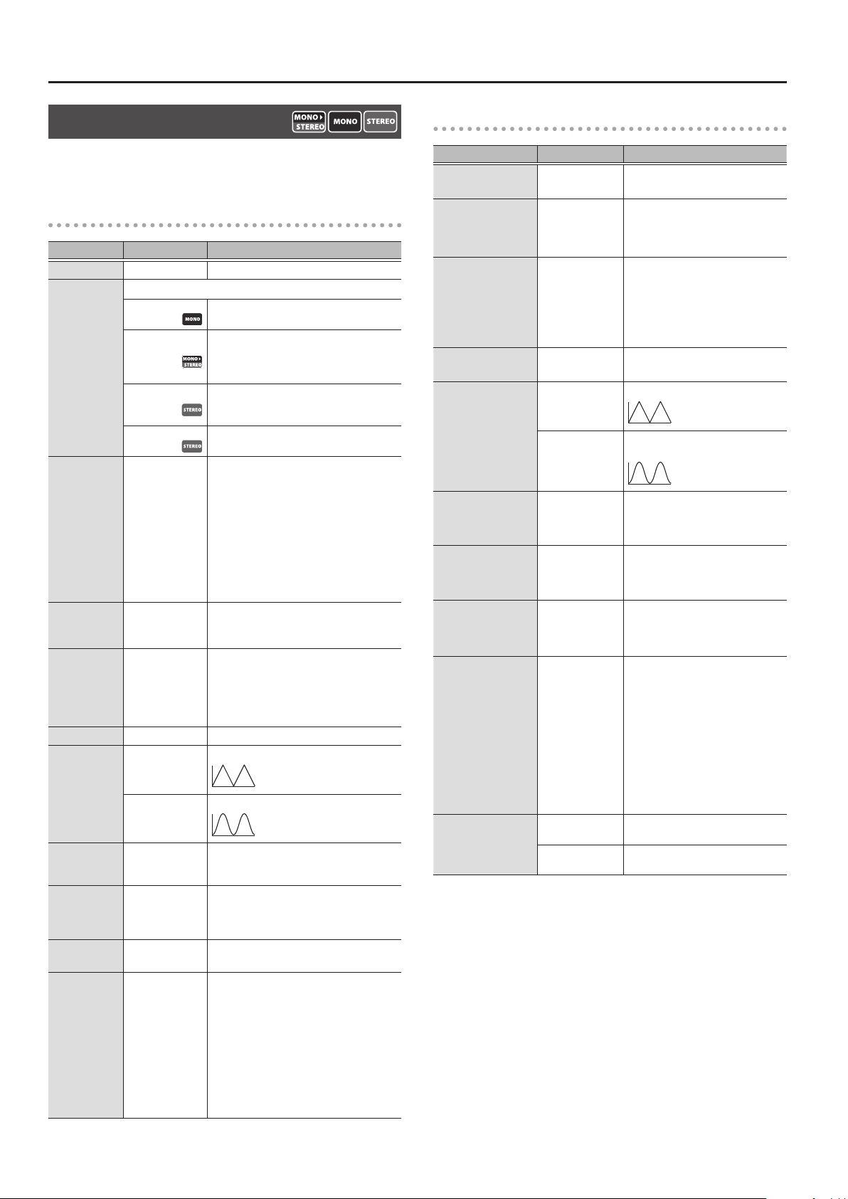
CHORUS
In this eect, a slightly detuned sound is added to the original sound
to add depth and breadth.
COMMON
Parameter Value Explanation
ON/OFF OFF, ON Turns this eect on/o.
Selection for the chorus mode.
MONO This chorus eect outputs the same sound
STEREO 1
TYPE
STEREO2
DUAL This lets you apply chorus independently to
RAT E
DEPTH 0–100
PRE-DELY
(PRE-DELAY)
E.LEVEL 0–100 Adjusts the volume of the eect sound.
WAVEFORM
LO CUT
HI CUT
D.LEVEL 0–100
BPM 40–250
0–100,
`
BPM Œ–
0.0ms–40.0ms
TRI
SINE
FLAT,
20.0Hz–20.0kHz
20.0Hz–20.0kHz,
FLAT
from both L channel and R channel.
This stereo chorus uses spatial synthesis,
with the direct sound output in the L
channel and the eect sound output in the
R channel.
This is a stereo chorus eect that adds
dierent chorus sounds to L channel and R
channel.
the L and R channels.
Adjusts the rate of the chorus eect.
* When set to BPM, the value of each
parameter will be set according to the
value of the “MASTER BPM” specied for
each patch. This makes it easier to achieve
eect sound settings that match the
tempo of the song.
* If, due to the tempo, the time is longer
than the range of allowable settings, it is
then synchronized to a period either 1/2
or 1/4 of that time.
Adjusts the depth of the chorus eect.
* To use it for doubling eect, set the value
to 0.
Adjusts the time needed for the eect sound
to be output after the direct sound has been
output. By setting a longer pre delay time,
you can obtain an eect that sounds like
more than one sound is being played at the
same time (doubling eect).
Produces a typical chorus eect.
Produces a deeper sense of modulation.
This sets the frequency at which the low
cut lter begins to take eect. When FLAT is
selected, the low cut lter will have no eect.
This sets the frequency at which the high
cut lter begins to take eect. When FLAT
is selected, the high cut lter will have no
eect.
Adjusts the volume of the direct sound.
Setting this to 0 cuts the direct sound.
Adjusts the BPM value for each patch.
* BPM (beats per minute) indicates the
number of quarter note beats that occur
each minute
* When you have an external MIDI
device connected, the MASTER BPM
synchronizes to the external MIDI devices
tempo, making it impossible to set the
MASTER BPM. To enable setting of the
MASTER BPM, set “SYNC CLOCK” (p. 47) to
“INTERNAL.”
DUAL
Parameter Value Explanation
1:RATE
2:RATE
1:DEPTH
2:DEPTH
1:PRE-DL
2:PRE-DL
1:LEVEL
2:LEVEL
1:WAVE
2:WAVE
1:LO CUT
2:LO CUT
1:HI CUT
2:HI CUT
D.LEVEL 0–100
BPM 40–250
OUTPUT
0–100,
`
BPM Œ–
0–100
0.0ms–40.0ms
0–100
TRI
SINE
FLAT,
20.0Hz–20.0kHz
20.0Hz–20.0kHz,
FLAT
MONO
STEREO
Adjusts the rate of the chorus eect.
Adjusts the depth of the chorus
eect.
* To use it for doubling eect, set
the value to 0.
Adjusts the time needed for the
eect sound to be output after the
direct sound has been output. By
setting a longer pre delay time, you
can obtain an eect that sounds like
more than one sound is being played
at the same time (doubling eect).
Adjusts the volume of the eect
sound.
Produces a typical chorus eect.
Produces a deeper sense of
modulation.
This sets the frequency at which the
low cut lter begins to take eect.
When FLAT is selected, the low cut
lter will have no eect.
This sets the frequency at which the
high cut lter begins to take eect.
When FLAT is selected, the high cut
lter will have no eect.
Adjusts the volume of the direct
sound.
Setting this to 0 cuts the direct
sound.
Adjusts the BPM value for each patch.
* BPM (beats per minute) indicates
the number of quarter note beats
that occur each minute
* When you have an external MIDI
device connected, the MASTER
BPM synchronizes to the external
MIDI devices tempo, making it
impossible to set the MASTER
BPM. To enable setting of the
MASTER BPM, set “SYNC CLOCK”
(p. 47) to “INTERNAL.”
This setting is appropriate for mono
output.
Produces a rich spaciousness when
stereo output is used.
12
Page 13
FX1–FX3
With FX1, FX2, and FX3, you can select the eect to be used from the
following. You can select the same eect for FX1, FX2, and FX3.
Parameter Value Explanation
ON/OFF OFF, ON Turns this eect on/o.
TYPE Refer to FX1/FX2/FX3 TYPE
FX1/FX2/FX3 TYPE
This is a list of the eects that can be selected for FX1/FX2/FX3.
Eect Name Explanation
AC.G SIM
(AC GUITAR SIM)
AC RESO
(AC RESONANCE)
AUTO WAH
CHORUS
CHO BASS
(CHORUS BASS)
C-VIBE
(CLASSIC-VIBE)
COMP
DEFRETR
(DEFRETTER)
DEFRET B
(DEFRETTER BASS)
DIST
(DISTORTION)
FEEDBAKR
(FEEDBACKER)
FLANGER
FLANGR B
(FLANGER BASS)
HARMONST
(HARMONIST)
HUMANIZR
(HUMANIZER)
OCTAVE
OCT BASS
(OCTAVE BASS)
OVERTONE
PAN
PHASER
PITCH SFT
(PITCH SHIFTER)
RING MOD
ROTARY This produces an eect like the sound of a rotary speaker.
SITAR SIM This simulates the sound of the sitar.
SLICER
This eect simulates the tonal character of an acoustic guitar.
This processor allows you to change the sound produced by
the pickup on an acoustic electric guitar, creating a richer
sound similar to that obtained with a microphone placed
close to the guitar.
This changes the ltering over a periodic cycle, providing an
automatic wah eect.
In this eect, a slightly detuned sound is added to the original
sound to add depth and breadth.
Although this resembles a phaser eect, it also provides a
unique undulation that you can’t get with a regular phaser.
This is an eect that produces a long sustain by evening out the
volume level of the input signal. You can also use it as a limiter
to suppress only the sound peaks and prevent distortion.
This simulates a fretless guitar.
This simulates a fretless bass.
This eect distorts the sound to obtain long sustain.
Generates feedback performance.
The anging eect gives a twisting, jet-airplane-like character
to the sound.
Harmonist is an eect where the amount of shifting is
adjusted according to an analysis of the guitar input, allowing
you to create harmony based on diatonic scales.
This can create human vowel-like sounds.
This adds a note one octave lower and a note two octaves
lower, creating a richer sound.
This eect uses MDP technology to add new harmonics to
the sound, producing resonance and richness that was not
present in the original sound.
With the volume level of the left and right sides alternately
changing, when playing sound in stereo, you can get an eect
that makes the guitar sound appear to y back and forth
between the speakers.
By adding varied-phase portions to the direct sound, the phaser
eect gives a whooshing, swirling character to the sound.
This eect changes the pitch of the original sound (up or
down) within a range of two octaves.
This creates a bell-like sound by ring-modulating the guitar
sound with the signal from the internal oscillator. The sound
can be unmusical and lack distinctive pitches.
This consecutively interrupts the sound to create the
impression that a rhythm backing phrase is being played.
Eect
Eect Name Explanation
SLW GEAR
(SLOW GEAR)
SG BASS
(SLOW GEAR BASS)
SND HOLD
(SOUND HOLD)
S-BEND Applies intense bending.
TOUCH WH
(TOUCH WAH)
TW BASS
(TOUCH WAH BASS)
TREMOLO Tremolo is an eect that creates a cyclic change in volume.
VIBRATO This eect creates vibrato by slightly modulating the pitch.
This produces a volume-swell eect (“violin-like” sound).
You can have sound played on the guitar be held
continuously. This eect allows you to perform the melody in
the upper registers while holding a note in the lower registers.
You can produce a wah eect with the lter changing in
response to the guitar level.
You can produce a wah eect with the lter changing in
response to the bass level.
AC.G SIM (AC. GUITAR SIMULATOR)
This eect simulates the tonal character of an acoustic guitar.
Parameter Value Explanation
BODY 0–100 Adjusts the body resonance.
LO -50–+50
HI -50–+50
LEVEL 0–100 Species the volume of the eect.
Species the sense of volume for the lowfrequency range.
Species the sense of volume for the highfrequency range.
AC RESO (AC RESONANCE)
This processor allows you to change the sound produced by the
pickup on an acoustic electric guitar, creating a richer sound similar to
that obtained with a microphone placed close to the guitar.
Parameter Value Explanation
NATURAL A natural and uncolored sound.
TYPE
RESO 0–100
TONE -50-+50 Adjusts the tone.
LEVEL 0–100 Species the volume of the eect.
WIDE
BRIGHT
Mellow sound that emphasizes the body
resonance
Brilliant sound with an extended highfrequency range
Use this knob to adjust the balance between
the body resonance eect of the acoustic
guitar and the direct sound of the pickup.
13
Page 14

Eect
AUTO WAH
This changes the ltering over a periodic cycle, providing an
automatic wah eect.
Parameter Value Explanation
Selects the wah mode.
LPF
FILTER
RAT E
DEPTH 0–100 Adjusts the depth of the eect.
E.LEVEL 0–100 Adjusts the volume of the eect sound.
FREQ 0–100
RESO 0–100
WAVEFORM TRI, SINE Selects a wave type.
DIR MIX 0–100 Adjusts the volume of the direct sound.
BPM 40–250
HPF
BPF
0–100,
BPM Œ–
Low pass lter. Passes only the low-frequency
region.
High pass lter. Passes only the highfrequency region.
Band pass lter. Passes only the specied
frequency region.
Adjusts the frequency (speed) of the change.
* When set to BPM, the value of each
parameter will be set according to the
value of the “MASTER BPM” specied for
each patch. This makes it easier to achieve
`
eect sound settings that match the
tempo of the song.
* If, due to the tempo, the time is longer
than the range of allowable settings, it is
then synchronized to a period either 1/2
or 1/4 of that time.
Adjusts the center frequency of the Wah
eect.
Adjusts the way in which the wah eect
applies to the area around the center
frequency.
Adjusts the BPM value for each patch.
* BPM (beats per minute) indicates the
number of quarter note beats that occur
each minute
* When you have an external MIDI
device connected, the MASTER BPM
synchronizes to the external MIDI devices
tempo, making it impossible to set the
MASTER BPM. To enable setting of the
MASTER BPM, set “SYNC CLOCK” (p. 47) to
“INTERNAL.”
CHORUS
In this eect, a slightly detuned sound is added to the original sound
to add depth and breadth.
COMMON
Parameter Value Explanation
ON/OFF OFF, ON Turns this eect on/o.
Selection for the chorus mode.
MONO This chorus eect outputs the same sound
STEREO 1
STEREO2
TYPE
DUAL This lets you apply chorus independently to
PRIME
CE-1 CHO
CE-1 VIB
RAT E
DEPTH 0–100
E.LEVEL 0–100 Adjusts the volume of the eect sound.
PRE-DELY *1 0.0ms–40.0ms
0–100,
BPM Œ–
TRI
`
from both L channel and R channel.
This stereo chorus uses spatial synthesis,
with the direct sound output in the L
channel and the eect sound output in the
R channel.
This is a stereo chorus eect that adds
dierent chorus sounds to L channel and
R channel.
the L and R channels.
This is BOSS’s proprietary chorus sound. It
provides spaciousness and depth that were
not previously obtainable.
The chorus sound of the CE-1.
The vibrato sound of the CE-1.
Adjusts the rate of the chorus eect.
* When set to BPM, the value of each
parameter will be set according to the
value of the “MASTER BPM” specied
for each patch. This makes it easier to
achieve eect sound settings that match
the tempo of the song.
* If, due to the tempo, the time is longer
than the range of allowable settings, it is
then synchronized to a period either 1/2
or 1/4 of that time.
Adjusts the depth of the chorus eect.
* To use it for doubling eect, set the
value to 0.
Adjusts the time needed for the eect
sound to be output after the direct sound
has been output. By setting a longer pre
delay time, you can obtain an eect that
sounds like more than one sound is being
played at the same time (doubling eect).
Produces a typical chorus eect.
14
WAVEFORM *1
SINE
LO CUT *1
HI CUT *1
D.LEVEL 0–100
FLAT,
20.0Hz–20.0kHz
20.0Hz–20.0kHz,
FLAT
Produces a deeper sense of modulation.
This sets the frequency at which the low
cut lter begins to take eect. When FLAT
is selected, the low cut lter will have no
eect.
This sets the frequency at which the high
cut lter begins to take eect. When FLAT
is selected, the high cut lter will have no
eect.
Adjusts the volume of the direct sound.
Setting this to 0 cuts the direct sound.
Page 15
Eect
Parameter Value Explanation
Adjusts the BPM value for each patch.
* BPM (beats per minute) indicates the
number of quarter note beats that occur
each minute
BPM 40–250
*1 Not shown if TYPE is set to CE-1 CHO or CE-1 VIB.
* When you have an external MIDI
device connected, the MASTER BPM
synchronizes to the external MIDI
devices tempo, making it impossible to
set the MASTER BPM. To enable setting
of the MASTER BPM, set “SYNC CLOCK”
(p. 47) to “INTERNAL.”
DUAL
Parameter Value Explanation
Adjusts the rate of the chorus eect.
* When set to BPM, the value of each
parameter will be set according
to the value of the “MASTER BPM”
1:RATE
2:RATE
1:DEPTH
2:DEPTH
1:PRE-DL
2:PRE-DL
1:LEVEL
2:LEVEL
1:WAVE
2:WAVE
0–100,
`
BPM Œ–
0–100
0.0ms–40.0ms
0–100 Adjusts the volume of the eect sound.
TRI
SINE
specied for each patch. This makes
it easier to achieve eect sound
settings that match the tempo of
the song.
* If, due to the tempo, the time is
longer than the range of allowable
settings, it is then synchronized to a
period either 1/2 or 1/4 of that time.
Adjusts the depth of the chorus eect.
* To use it for doubling eect, set the
value to 0.
Adjusts the time needed for the eect
sound to be output after the direct
sound has been output. By setting a
longer pre delay time, you can obtain an
eect that sounds like more than one
sound is being played at the same time
(doubling eect).
Produces a typical chorus eect.
Produces a deeper sense of modulation.
PRIME
Parameter Value Explanation
SWEETNES
(SWEETNESS)
BELL 0–100
OUTPUT
0–100
MONO
STEREO
Higher values produce a more
enveloping sound.
Higher values produce a more brilliant
sound.
This setting is appropriate for mono
output.
Produces a rich spaciousness when
stereo output is used.
CE-1 CHORUS, CE-1 VIBRATO
Parameter Value Explanation
PREAMP
(PREAMP SW)
GAIN
(PREAMP GAIN)
LEVEL
(PREAMP LEVEL)
OFF, ON
0–100
0–100
Species whether the CE-1’s preamp is
simulated (ON) or not simulated (OFF).
Adjusts the gain of the preamp. Higher
settings will produce distortion.
Adjusts the volume of the preamp.
1:LO CUT
2:LO CUT
1:HI CUT
2:HI CUT
D.LEVEL 0–100
BPM 40–250
FLAT,
20.0Hz–20.0kHz
20.0Hz–20.0kHz,
FLAT
This sets the frequency at which the low
cut lter begins to take eect. When
FLAT is selected, the low cut lter will
have no eect.
This sets the frequency at which the
high cut lter begins to take eect.
When FLAT is selected, the high cut lter
will have no eect.
Adjusts the volume of the direct sound.
Setting this to 0 cuts the direct sound.
Adjusts the BPM value for each patch.
* BPM (beats per minute) indicates the
number of quarter note beats that
occur each minute
* When you have an external MIDI
device connected, the MASTER BPM
synchronizes to the external MIDI
devices tempo, making it impossible
to set the MASTER BPM. To enable
setting of the MASTER BPM, set “SYNC
CLOCK” (p. 47) to “INTERNAL.”
15
Page 16
Eect
CHO BASS (CHORUS BASS)
This is a chorus eect for bass.
Parameter Value Explanation
ON/OFF OFF, ON Turns this eect on/o.
Selection for the chorus mode.
MONO This chorus eect outputs the same sound
TYPE
RAT E
DEPTH 0–100
E.LEVEL 0–100 Adjusts the volume of the eect sound.
LO CUT *1
HI CUT *1
BPM 40–250
STEREO 1
STEREO2
0–100,
`
BPM Œ–
FLAT,
20.0Hz–20.0kHz
20.0Hz–20.0kHz,
FLAT
from both L channel and R channel.
This stereo chorus uses spatial synthesis,
with the direct sound output in the L
channel and the eect sound output in the
R channel.
This is a stereo chorus eect that adds
dierent chorus sounds to L channel and
R channel.
Adjusts the rate of the chorus eect.
* When set to BPM, the value of each
parameter will be set according to the
value of the “MASTER BPM” specied
for each patch. This makes it easier to
achieve eect sound settings that match
the tempo of the song.
* If, due to the tempo, the time is longer
than the range of allowable settings, it is
then synchronized to a period either 1/2
or 1/4 of that time.
Adjusts the depth of the chorus eect.
* To use it for doubling eect, set the
value to 0.
This sets the frequency at which the low
cut lter begins to take eect. When FLAT
is selected, the low cut lter will have no
eect.
This sets the frequency at which the high
cut lter begins to take eect. When FLAT
is selected, the high cut lter will have no
eect.
Adjusts the BPM value for each patch.
* BPM (beats per minute) indicates the
number of quarter note beats that occur
each minute
* When you have an external MIDI
device connected, the MASTER BPM
synchronizes to the external MIDI
devices tempo, making it impossible to
set the MASTER BPM. To enable setting
of the MASTER BPM, set “SYNC CLOCK”
(p. 47) to “INTERNAL.”
C-VIBE (CLASSIC VIBE)
Although this resembles a phaser eect, it also provides a unique
undulation that you can’t get with a regular phaser.
Parameter Value Explanation
Direct sound and eect sound are mixed and
output.
Adjusts the rate of the eect.
* When set to BPM, the value of each
parameter will be set according to the
value of the “MASTER BPM” specied for
each patch. This makes it easier to achieve
`
eect sound settings that match the
tempo of the song.
* If, due to the tempo, the time is longer than
the range of allowable settings, it is then
synchronized to a period either 1/2 or 1/4
of that time.
Adjusts the BPM value for each patch.
* BPM (beats per minute) indicates the
number of quarter note beats that occur
each minute
* When you have an external MIDI device
connected, the MASTER BPM synchronizes
to the external MIDI devices tempo,
making it impossible to set the MASTER
BPM. To enable setting of the MASTER BPM,
set “SYNC CLOCK” (p. 47) to “INTERNAL.”
MODE
RAT E
DEPTH
E.LEVEL
BPM
CHORUS
VIBRATO Only eect sound is output.
0–100,
BPM Œ–
0–100 Adjusts the depth of the eect.
0–100 Adjusts the tone.
40–250
COMP (COMPRESSOR)
This is an eect that produces a long sustain by evening out the
volume level of the input signal.
Parameter Value Explanation
ON/OFF OFF, ON Turns this eect on/o.
BOSS COMP
X-COMP
D-COMP
TYPE
ORANGE This is modeled on the sound of the Dan
STEREO COMP
This models a BOSS CS-3.
This uses MDP to provide a consistently natural
playing feel and sound that responds to the
pitch range and dynamics of your phrases.
This models a MXR DynaComp.
Armstrong ORANGE SQUEEZER.
This selects a stereo compressor.
16
X-BASS COMP
THRESHOLD
*1
SUSTAIN *2 0–100
ATTAC K 0–100
LEVEL 0–100 Adjusts the volume.
TONE -50–+50 Adjusts the tone.
RATIO 1:1–INF:1 Selects the compression ratio.
DIR MIX 0–100 Adjusts the volume of the direct sound.
*1 Setting available when TYPE is set to X-BASS COM.
*2 Not shown if TYPE is set to X-BASS COMP.
0–100
This is a compressor for bass that uses MDP.
Adjust this as appropriate for the input
signal. When the input signal level exceeds
this threshold level, compression will be
applied.
Adjusts the range (time) over which lowlevel signals are boosted. Larger values will
result in longer sustain.
Adjusts the strength of the attack when
picking.
Page 17
Eect
DEFRETR (DEFRETTER)
This simulates a fretless guitar.
Parameter Value Explanation
SENS 0–100
DEPTH 0–100 This controls the rate of the harmonics.
TONE -50–+50
E.LEVEL 0–100 Adjusts the volume of the eect sound.
ATTAC K 0–100 Adjusts the attack of the picking sound.
RESO 0–100
DIR MIX 0–100 Adjusts the volume of the direct sound.
This controls the input sensitivity of the
defretter.
Adjusts the amount of blurring between the
notes.
Adds a characteristically resonant quality to the
sound.
DEFRET B (DEFRETTER BASS)
This simulates a fretless bass.
Parameter Value Explanation
SENS 0–100
ATTAC K 0–100 Adjusts the attack of the picking sound.
TONE -50–+50
E.LEVEL 0–100 Adjusts the volume of the eect sound.
DIR MIX 0–100 Adjusts the volume of the direct sound.
This controls the input sensitivity of the
defretter.
Adjusts the amount of blurring between the
notes.
DIST (DISTORTION)
This eect distorts the sound to create long sustain.
Parameter Value Explanation
ON/OFF OFF, ON Turns this eect on/o.
TYPE Refer to “DISTORTION TYPE” (p. 17)
DRIVE 0–120 Adjusts the depth of distortion.
TONE -50–+50 Adjusts the tone.
LEVEL 0–100 Adjusts the volume of the eect sound.
Adjusts the tone for the low frequency range.
BOTTOM -50–+50
DIR MIX 0–100 Adjusts the volume of the direct sound.
SOLO SW OFF, ON The tone to one suitable for solos.
SOLO LVL 0–100
DISTORTION TYPE
This is a list of distortion types that can be selected for DISTORTION.
Type Explanation
MID
CLEAN
TREBLE This is a booster that has bright characteristics.
CRUNCH
This is a booster with unique characteristics in the midrange.
Making the connection before the AIRD PREAMP produces
sound suitable for solos.
This not only functions as a booster, but also produces a clean
tone that has punch even when used alone.
A lustrous crunch sound with an added element of amp
distortion.
Turning this to the left (counterclockwise)
produces a sound with the low end cut; turning it
to the right boosts the low end in the sound.
Adjusts the volume level when the SOLO SW is
ON.
Type Explanation
NATURAL
WARM OD This is a warm overdrive.
FAT DS A distortion sound with thick distortion.
LEAD DS
METAL DS
OCT FUZZ A fuzz sound with rich harmonic content.
A-DIST
X-OD
X-DIST
BLUES OD
OD-1
T-SCREAM This models an Ibanez TS-808.
TURBO OD This is the high-gain overdrive sound of the BOSS OD-2.
DIST This gives a basic, traditional distortion sound.
CENTA OD This models a KLON CENTAUR.
RAT This models a Proco RAT.
GUV DS This models a Marshall GUV’ NOR.
DIST+ This models the sound of the MXR DISTORTION+.
MTL ZONE
HM-2
MTL CORE
60S FUZZ
MUFF FUZ This models an Electro-Harmonix Big Mu π.
BASS OD Overdrive tuned especially for use with basses.
BASS DS Distortion tuned especially for use with basses.
BASS MT Wild, radical distortion sound.
BASS FUZ Fuzz tuned especially for use with basses.
HI BAND
X-BASS
BASS DRV This models a TECH21 SANSAMP BASS DRIVER DI.
BASS DI This models a MXR Bass D.I.+.
* Company names and product names appearing in this document are registered
trademarks or trademarks of their respective owners.
* In this manual, company names and product names of the respective owners
are used because it is the most practical way of describing the sounds that are
emulated using DSP technology.
This is an overdrive sound that provides distortion with a natural
feeling.
Produces a distortion sound with both the smoothness of an
overdrive along with a deep distortion.
This is a distortion sound that is ideal for performances of heavy
ris.
This uses MDP technology to obtain ideal distortion in all ranges
of the guitar, from low to high.
This is an overdrive that uses MDP to obtain the distortion that’s
most appropriate in each pitch range.
This is a distortion that uses MDP to obtain the distortion that’s
most appropriate in each pitch range.
This is a crunch sound of the BOSS BD-2.
This produces distortion that faithfully reproduces the nuances
of picking.
This models the sound of the BOSS OD-1.
This produces sweet, mild distortion.
This models the sound of the BOSS MT-2.
It produces a wide range of metal sounds, from old style to slash
metal.
This models the sound of the BOSS HM-2.
It produces distinctive cranked-up distortion sound with
compression.
This is the sound of the BOSS ML-2 which is ideal for high speed
metal ris.
This models a FUZZFACE.
It produces a fat fuzz sound.
With this eect, distortion is applied only to the high frequency
sounds, and not to the sounds in the low frequency range.
This eect uses MDP to provide ideal distortion in all pitch
ranges of the bass, from low to high.
17
Page 18
Eect
FEEDBAKR (FEEDBACKER)
Generates feedback performance.
* Note that the notes you want to apply feedback to must be played
singly and cleanly.
Parameter Value Explanation
NORMAL
MODE
OSC
TRIGGER OFF, ON Feedback is applied if this is turned ON.
DEPTH *1 0–100
RISE TIME *2 0–100
OCT RISE *2 0–100
FEEDBACK *2 0–100 Adjusts the volume of the feedback sound.
OCT FBK*2 0–100
VIB RATE *2 0–100
VIB DEPT *2 0–100
*1 MODE=NORMAL only
*2 MODE=OSC only
Analyzes the pitch of the guitar sound being
input, and then creates a feedback sound.
An articial feedback sound will be created
internally. When OSC is selected, the eect is
activated after a single note is played and the
note stabilizes. A feedback eect is created when
the eect switches on; the feedback disappears
when the OSC eect switches o.
Adjusts the ease with which feedback will occur
when the FEEDBACKER is on.
This determines the time needed for the volume
of the feedback sound to reach its maximum
from the moment the eect is turned on.
This determines the time needed for the volume
of the one octave higher feedback sound to
reach its maximum from the moment the eect
is turned on.
Adjusts the volume of the one octave higher
feedback sound.
Adjusts the rate of the vibrato when the
FEEDBACKER is on.
Adjusts the depth of the vibrato when the
FEEDBACKER is on.
FLANGER/FLANGR B (FLANGER B)
The anging eect gives a twisting, jet-airplane-like character to the
sound.
Parameter Value Explanation
This sets the rate of the anging eect.
* When set to BPM, the value of each
parameter will be set according to the
value of the “MASTER BPM” specied
RAT E
DEPTH 0–100
RESO 0–100
MANUAL 0–100
TURBO OFF, ON
WAVEFORM TRI, SINE Selects the type of wave.
STEP
SEPARATE
E.LEVEL 0–100 Adjusts the volume of the anger.
LO DAMP -100–0
HI DAMP -100–0
LO CUT
HI CUT
DIR MIX 0–100 Adjusts the volume of the direct sound.
BPM 40–250
0–100,
`
BPM Œ–
OFF,
0–100,
`
BPM Œ–
0, 15, 30, 45, 60,
75, 90, 105, 120,
135, 150, 165, 180
FLAT,
20.0Hz–20.0kHz
20.0Hz–20.0kHz,
FLAT
for each patch. This makes it easier
to achieve eect sound settings that
match the tempo of the song.
* If, due to the tempo, the time is longer
than the range of allowable settings, it
is then synchronized to a period either
1/2 or 1/4 of that time.
Determines the depth of the anging
eect.
Determines the amount of resonance
(feedback). Increasing the value will
emphasize the eect, creating a more
unusual sound.
Adjusts the center frequency at which to
apply the eect.
If this is “ON,” a more intense eect is
produced.
Adjusts the rate of the step function which
varies the rotation in a step-wise manner.
Higher settings make the change occur in
smaller steps. Turn this “OFF” if you don’t
want to use the step function.
Adjusts the diusion. The diusion
increases as the value increases.
Adjusts the amount of feedback for the
low-frequency region.
Adjusts the amount of feedback for the
high-frequency region.
This sets the frequency at which the low
cut lter begins to take eect. When FLAT
is selected, the low cut lter will have no
eect.
This sets the frequency at which the high
cut lter begins to take eect. When FLAT
is selected, the high cut lter will have no
eect.
Adjusts the BPM value for each patch.
* BPM (beats per minute) indicates the
number of quarter note beats that
occur each minute
* When you have an external MIDI
device connected, the MASTER BPM
synchronizes to the external MIDI
devices tempo, making it impossible to
set the MASTER BPM. To enable setting
of the MASTER BPM, set “SYNC CLOCK”
(p. 47) to “INTERNAL.”
18
Page 19

Eect
HARMONST (HARMONIST)
Harmonist is an eect where the amount of shifting is adjusted
according to an analysis of the guitar input, allowing you to create
harmony based on diatonic scales.
* Because of the need to analyze the pitch, chords (two or more
sounds played simultaneously) cannot be played. Be sure to mute
all the other strings and play only one note at a time.
* When you are to play the next string while a certain sound is still
playing, mute the previous sound and then play the next one with
a clear attack. If the unit cannot detect the attack, it may not sound
correctly.
* The sensitivity may vary according to the guitar’s TONE knob and
pickup type.
Parameter Value Explanation
Selects the number of voices for the pitch shift sound.
VOICE
1:HARMO
2:HARMO
1VOICE One-voice pitch-shifted sound output in
2MONO Two-voice pitch-shifted sound (HR1, HR2)
2STEREO Two-voice pitch-shifted sound (HR1, HR2)
-2oct–+2oct,
USER
mono.
output in mono.
output through left and right channels.
This determines the pitch of the sound
added to the input sound, when you are
making a harmony.
It allows you to set it by up to 2 octaves
higher or lower than the input sound. When
the scale is set to USER, this parameter sets
the user scale number to be used.
The key setting corresponds to the key of
the song (¾, ²) as follows.
Major
USER SCALE
* Eective with USER selected for HARM parameter.
Parameter Value
C
²
D
D
²
E
E
F
¾
F
G
²
A
A
²
B
B
Specify the note name of the output sound. The minus (-) and plus (+) symbols
indicate sounds above or below the specied original note.
Triangles next to the note names indicate octaves.
One downward-pointing triangle indicates a note one octave below the note
displayed; two triangles indicates a two-octave drop.
One upward-pointing triangle indicates a note one octave above the note displayed;
two triangles indicates a two-octave rise.
C– C–C– C– C
D²– D²–D²– D²– D
D– D–D– D– D
E²– E²–E²– E²– E
E– E–E– E– E
F– F–F– F– F
F¾– F¾–F¾– F¾– F
G– G–G– G– G
A²– A²–A²– A²– A
A– A–A– A– A
B²– B²–B²– B²– B
B– B–B– B– B
²
²
¾
²
²
KEY
1:LEVEL
2:LEVEL
1:PRE-DL
2:PRE-DL
1:FEEDBK
D.LEVEL
BPM 40–250
C (Am)–
B (G#m)
0–100 Adjusts the volume of the harmony sound.
0–300ms,
BPM `–
0–100
0–100 Adjusts the volume of the direct sound.
Minor
Major
Minor
Adjusts the time from when the direct
sound is heard until the harmonist sounds
are heard. Normally you can leave this set
at 0 ms.
* When set to BPM, the value of each
parameter will be set according to the
Œ
value of the “MASTER BPM” specied
for each patch. This makes it easier to
achieve eect sound settings that match
the tempo of the song.
* If, due to the tempo, the time is longer
than the range of allowable settings, it is
then synchronized to a period either 1/2
or 1/4 of that time.
Adjusts the feedback amount of the
harmonist sound.
Adjusts the BPM value for each patch.
* BPM (beats per minute) indicates the
number of quarter note beats that occur
each minute
* When you have an external MIDI
device connected, the MASTER BPM
synchronizes to the external MIDI devices
tempo, making it impossible to set the
MASTER BPM. To enable setting of the
MASTER BPM, set “SYNC CLOCK” (p. 47) to
“INTERNAL.”
19
Page 20

Eect
HUMANIZR (HUMANIZER)
This can create human vowel-like sounds.
Parameter Value Explanation
This sets the mode that switches the vowels.
MODE
VOWEL 1 a, e, i, o, u Selects the rst vowel.
VOWEL 2 a, e, i, o, u Selects the second vowel.
SENS *1 0–100
RAT E
DEPTH 0–100 Adjusts the depth of the eect.
MANUAL *2 0–100
LEVEL 0–100 Adjusts the tone.
BPM 40–250
*1 Setting available when MODE is set to PICKING.
*2 Setting available when MODE is set to AUTO.
PICKING
AUTO
0–100,
BPM Œ–
`
It changes from VOWEL 1 to VOWEL 2 along
with the picking. The time spent for the
change is adjusted with the rate.
By adjusting the rate and depth, two vowels
(VOWEL 1 and VOWEL 2) can be switched
automatically.
Adjusts the sensitivity of the humanizer.
When it is set to a lower value, no eect
of the humanizer is obtained with weaker
picking, while stronger picking produces
the eect. When it is set to a higher value,
the eect of the humanizer can be obtained
whether the picking is weak or strong.
Adjusts the cycle for changing the two
vowels.
* When set to BPM, the value of each
parameter will be set according to the
value of the “MASTER BPM” specied for
each patch. This makes it easier to achieve
eect sound settings that match the
tempo of the song.
* If, due to the tempo, the time is longer
than the range of allowable settings, it is
then synchronized to a period either 1/2
or 1/4 of that time.
This determines the point where the two
vowels are switched. When it is set to 50,
VOWEL 1 and VOWEL 2 are switched in the
same length of time. When it is set to lower
than 50, the time for VOWEL 1 is shorter.
When it is set to higher than 50, the time for
VOWEL 1 is longer.
Adjusts the BPM value for each patch.
* BPM (beats per minute) indicates the
number of quarter note beats that occur
each minute
* When you have an external MIDI
device connected, the MASTER BPM
synchronizes to the external MIDI devices
tempo, making it impossible to set the
MASTER BPM. To enable setting of the
MASTER BPM, set “SYNC CLOCK” (p. 47) to
“INTERNAL.”
OCTAVE
This adds a note one octave lower and a note two octaves lower,
creating a richer sound.
Parameter Value Explanation
Adds a note one octave lower and a note two
MONO
TYPE
POLY
-2OCT *1 0–100
-1OCT *1 0–100
D.LEVEL 0–100 Adjusts the volume of the direct sound.
RANGE *2 0–100
OC.LEVEL *2 0–100
*1 Setting available when TYPE is set to MONO.
*2 Setting available when TYPE is set to POLY.
octaves lower than the input.
This supports mono input.
Adds a note one octave lower than the input.
This supports polyphonic input.
Adjusts the volume of the sound two octave
below.
Adjusts the volume of the sound one octaves
below.
This selects the register to which the eect
is applied.
Adjusts the volume of the sound one octave
below.
OCT BASS (OCTAVE BASS)
This is an OCTAVE eect for bass.
Parameter Value Explanation
-2OCT 0–100
-1OCT 0–100
D.LEVEL 0–100 Adjusts the volume of the direct sound.
Adjusts the volume of the sound two octave
below.
Adjusts the volume of the sound one octaves
below.
OVERTONE
This eect uses MDP technology to add new harmonics to the sound,
producing resonance and richness that was not present in the original
sound.
Parameter Value Explanation
LOWER 0–100
UPPER 0–100
UNISON 0–100
D.LEVEL 0–100 Adjusts the volume of the direct sound.
DETUNE 0–100
LO -50–+50
HI -50–+50
OUTPUT
MONO,
STEREO
Adjusts the volume of the harmonic one octave
below.
Adjusts the volume of the harmonic one octave
above.
Adjusts the volume of added sound whose pitch
is slightly shifted relative to the direct sound.
Adjusts the amount of the detune eect that
adds depth to the sound.
Adjusts the tonal character of the low-frequency
range.
Adjusts the tonal character of the high-frequency
range.
Selects the type of output.
20
Page 21

Eect
PAN
With the volume level of the left and right sides alternately changing,
when playing sound in stereo, you can get an eect that makes the
guitar sound appear to y back and forth between the speakers.
Parameter Value Explanation
Adjusts the frequency (speed) of the
change.
* When set to BPM, the value of each
parameter will be set according
to the value of the “MASTER BPM”
RAT E
DEPTH 0–100 Adjusts the depth of the eect.
WAVEFORM 0–100
E.LEVEL 0–100 Adjusts the volume.
DIR MIX 0–100 Adjusts the volume of the direct sound.
BPM 40–250
0–100,
BPM Œ–
`
specied for each patch. This makes
it easier to achieve eect sound
settings that match the tempo of
the song.
* If, due to the tempo, the time is
longer than the range of allowable
settings, it is then synchronized to a
period either 1/2 or 1/4 of that time.
Adjusts changes in volume level.
A higher value will steepen wave’s
shape.
Adjusts the BPM value for each patch.
* BPM (beats per minute) indicates the
number of quarter note beats that
occur each minute
* When you have an external MIDI
device connected, the MASTER BPM
synchronizes to the external MIDI
devices tempo, making it impossible
to set the MASTER BPM. To enable
setting of the MASTER BPM, set
“SYNC CLOCK” (p. 47) to “INTERNAL.”
PHASER
By adding varied-phase portions to the direct sound, the phaser eect
gives a whooshing, swirling character to the sound.
Parameter Value Explanation
Selects the PHASER type.
TYPE
STAGE *1
RAT E
DEPTH 0–100 Determines the depth of the phaser eect.
RESO *1 0–100
MANUAL *1 0–100
PRIME
SCRIPT
2, 4, 8, 16,
24STAGE
0–100,
BPM Œ–
An original BOSS phaser. This provides
modulation that is not obtainable from
previous units.
Models the MXR Phase 90 which was
manufactured during the ‘70s.
Selects the number of stages that the phaser
eect will use.
This sets the rate of the phaser eect.
* When set to BPM, the value of each
parameter will be set according to the
value of the “MASTER BPM” specied
for each patch. This makes it easier to
`
achieve eect sound settings that match
the tempo of the song.
* If, due to the tempo, the time is longer
than the range of allowable settings, it is
then synchronized to a period either 1/2
or 1/4 of that time.
Determines the amount of resonance
(feedback). Increasing the value will
emphasize the eect, creating a more
unusual sound.
Adjusts the center frequency of the phaser
eect.
Parameter Value Explanation
WAVEFORM *1 TRI, SINE Selects the type of wave.
This sets the cycle of the step function that
changes the rate and depth. When it is set
to a higher value, the change will be ner.
Set this to “O” when not using the Step
function.
* When set to BPM, the value of each
STEP *1
BI-PHASE *1 OFF, ON
SEPARATE *1
LO DAMP *1 -100–0
HI DAMP *1 -100–0
LO CUT *1
HI CUT *1
E.LEVEL 0–100 Adjusts the volume.
DIR MIX 0–100 Adjusts the volume of the direct sound.
BPM 40–250
*1 Setting available when TYPE is set to PRIME.
* Company names and product names appearing in this document are registered
trademarks or trademarks of their respective owners.
* In this manual, company names and product names of the respective owners
are used because it is the most practical way of describing the sounds that are
emulated using DSP technology.
OFF, 0–100,
`
BPM Œ–
0, 15, 30, 45,
60, 75, 90, 105,
120, 135, 150,
165, 180
FLAT,
20.0Hz–
20.0kHz
20.0Hz–
20.0kHz,
FLAT
parameter will be set according to the
value of the “MASTER BPM” specied
for each patch. This makes it easier to
achieve eect sound settings that match
the tempo of the song.
* If, due to the tempo, the time is longer
than the range of allowable settings, it is
then synchronized to a period either 1/2
or 1/4 of that time.
Species whether the two phase shift
circuits are connected in series (ON) or not
(OFF).
Adjusts the diusion. The diusion increases
as the value increases.
Adjusts the amount of feedback for the lowfrequency region.
Adjusts the amount of feedback for the
high-frequency region.
This sets the frequency at which the low
cut lter begins to take eect. When FLAT
is selected, the low cut lter will have no
eect.
This sets the frequency at which the high
cut lter begins to take eect. When FLAT
is selected, the high cut lter will have no
eect.
Adjusts the BPM value for each patch.
* BPM (beats per minute) indicates the
number of quarter note beats that occur
each minute
* When you have an external MIDI
device connected, the MASTER BPM
synchronizes to the external MIDI devices
tempo, making it impossible to set the
MASTER BPM. To enable setting of the
MASTER BPM, set “SYNC CLOCK” (p. 47) to
“INTERNAL.”
21
Page 22

Eect
PITCH SFT (PITCH SHIFTER)
This eect changes the pitch of the original sound (up or down)
within a range of two octaves.
Parameter Value Explanation
Selects the number of voices for the pitch shift sound.
1VOICE One-voice pitch-shifted sound output in
VOICE
1:PITCH
2:PITCH
D.LEVEL 0–100 Adjusts the volume of the direct sound.
1:MODE
2:MODE
1:FINE
2:FINE
1:PRE-DL
2:PRE-DL
1:LEVEL
2:LEVEL
1:FEEDBK 0–100
BPM 40–250
2MONO Two-voice pitch-shifted sound (PS1, PS2)
2STEREO Two-voice pitch-shifted sound (PS1, PS2)
-24–+24
Selection for the pitch shifter mode.
FAST,
MEDIUM,
SLOW
MONO
-50–+50
0ms–300ms,
Œ
BPM `–
0–100 Adjusts the volume of the pitch shifter.
mono.
output in mono.
output through left and right channels.
Adjusts the amount of pitch shift (the
amount of interval) in semitone steps.
The response is slower in the order
of FAST, MEDIUM and SLOW, but the
modulation is lessened in the same order.
MONO is used for inputting single notes.
* You may be unable to produce
the intended eect when playing
chords (two or more notes played
simultaneously).
Make ne adjustments to the interval. The
amount of the change in the Fine 100 is
equivalent to that of the Pitch 1.
Adjusts the time from when the direct
sound is heard until the pitch shifted
sounds are heard. Normally you can leave
this set at 0 ms.
* When set to BPM, the value of each
parameter will be set according to the
value of the “MASTER BPM” specied
for each patch. This makes it easier
to achieve eect sound settings that
match the tempo of the song.
* If, due to the tempo, the time is longer
than the range of allowable settings, it
is then synchronized to a period either
1/2 or 1/4 of that time.
Adjusts the feedback amount of the pitch
shift sound.
Adjusts the BPM value for each patch.
* BPM (beats per minute) indicates the
number of quarter note beats that
occur each minute
* When you have an external MIDI
device connected, the MASTER BPM
synchronizes to the external MIDI
devices tempo, making it impossible to
set the MASTER BPM. To enable setting
of the MASTER BPM, set “SYNC CLOCK”
(p. 47) to “INTERNAL.”
RING MOD
This creates a bell-like sound by ring-modulating the guitar sound
with the signal from the internal oscillator.
The sound can be unmusical and lack distinctive pitches.
Parameter Value Explanation
If this is ON, the oscillator frequency changes
according to the pitch of the input sound,
INTELLI OFF, ON
FREQ 0–100
MOD RATE
MOD DEPT 0–100
E.LEVEL 0–100 Adjusts the volume of the eect sound.
DIR MIX 0–100 Adjusts the volume of the direct sound.
BPM 40–250
0–100,
BPM Œ–
producing a pitched sound. In this case, the
expected eect does not occur if the pitch
of the guitar sound is not detected correctly.
We recommend that you use this with singlenote playing.
Adjusts the frequency of the internal
oscillator.
Adjusts the rate at which the internal
oscillator is modulated.
* When set to BPM, the value of each
parameter will be set according to the
value of the “MASTER BPM” specied for
`
each patch. This makes it easier to achieve
eect sound settings that match the
tempo of the song.
* If, due to the tempo, the time is longer
than the range of allowable settings, it is
then synchronized to a period either 1/2
or 1/4 of that time.
Adjusts the depth to which the internal
oscillator is modulated.
Adjusts the BPM value for each patch.
* BPM (beats per minute) indicates the
number of quarter note beats that occur
each minute
* When you have an external MIDI
device connected, the MASTER BPM
synchronizes to the external MIDI devices
tempo, making it impossible to set the
MASTER BPM. To enable setting of the
MASTER BPM, set “SYNC CLOCK” (p. 47) to
“INTERNAL.”
22
Page 23

Eect
ROTARY
This produces an eect like the sound of a rotary speaker.
Parameter Value Explanation
SPEED SLOW, FAST
SLOW
FAST
E.LEVEL 0–100 Adjusts the volume.
RISE TIME 0–100
FALL TIME 0–100
MIC DIST 0–100
ROT/HORN 100:0–0:100
DRIVE 0–100
DIR MIX 0–100 Adjusts the volume of the direct sound.
BPM 40–250
0–100,
BPM Œ–
0–100,
BPM Œ–
`
`
This parameter changes the simulated
speaker’s rotating speed (SLOW or FAST).
This parameter adjusts the SPEED SELECT
of rotation when set to “SLOW.”
This parameter adjusts the SPEED SELECT
of rotation when set to “FAST.”
This parameter adjusts the time it takes
for the rotation SPEED SELECT to change
when switched from “SLOW” to “FAST.”
This parameter adjusts the time it takes
for the rotation SPEED SELECT to change
when switched from “FAST” to “SLOW.”
Adjusts the distance between the horn/
rotor and the mic.
Adjusts the volume balance between the
horn and rotor.
Adjusts the amount of distortion in the
preamp.
Adjusts the BPM value for each patch.
* BPM (beats per minute) indicates the
number of quarter note beats that occur
each minute
* When you have an external MIDI
device connected, the MASTER BPM
synchronizes to the external MIDI
devices tempo, making it impossible to
set the MASTER BPM. To enable setting
of the MASTER BPM, set “SYNC CLOCK”
(p. 47) to “INTERNAL.”
SLICER
This consecutively interrupts the sound to create the impression that
a rhythm backing phrase is being played.
Parameter Value Explanation
PATTERN P1–P20
RAT E
TRIGGER OFF, ON
E.LEVEL 0–100 Adjusts the volume of the eect sound.
ATTAC K 0–100 Adjusts the volume of the attacks for the slice pattern.
DUTY 1–99 Adjusts the duration of the sound for the slice pattern.
DIR MIX 0–100 Adjusts the volume of the direct sound.
BPM 40–250
0–100,
BPM Œ–
Select the slice pattern that will be used to cut the
sound.
Adjust the rate at which the sound will be cut.
* When set to BPM, the value of each parameter
will be set according to the value of the “MASTER
BPM” specied for each patch. This makes it easier
to achieve eect sound settings that match the
`
tempo of the song.
* If, due to the tempo, the time is longer than the
range of allowable settings, it is then synchronized
to a period either 1/2 or 1/4 of that time.
When you switch this from OFF to ON, the rhythm
pattern returns to its beginning.
5 When the patch is written, the TRIGGER parameter
is stored in the OFF state.
Adjusts the BPM value for each patch.
* BPM (beats per minute) indicates the number of
quarter note beats that occur each minute
* When you have an external MIDI device connected,
the MASTER BPM synchronizes to the external
MIDI devices tempo, making it impossible to set
the MASTER BPM. To enable setting of the MASTER
BPM, set “SYNC CLOCK” (p. 47) to “INTERNAL.”
SITAR SIM.
This simulates the sound of the sitar.
Parameter Value Explanation
Adjusts the sensitivity of the sitar. When it is set
to a lower value, no eect of the sitar is obtained
SENS 0–100
DEPTH 0–100 This adjusts the amount of eect applied.
TONE -50–+50
E.LEVEL 0–100 Adjust the volume of the sitar sound.
RESO 0–100 This adjusts the undulation of the resonance.
BUZZ 0–100
DIR MIX 0–100 Adjusts the volume of the direct sound.
with weaker picking, while stronger picking
produces the eect. When it is set to a higher
value, the eect of the sitar can be obtained
whether the picking is weak or strong.
This adjusts the tone. The high end is boosted as
the value increases.
Adjusts the amount of characteristic buzz
produced by the “buzz bridge” when the strings
make contact with it.
SLW GEAR (SLOW GEAR)/ SG BASS (SLOW GEAR BASS)
This produces a volume-swell eect (“violin-like” sound).
Parameter Value Explanation
Adjusts the sensitivity of the slow gear. When it is set
to a lower value, the eect of the slow gear can be
SENS 0–100
RISE TIME 0–100
LEVEL 0–100 Adjusts the volume of the eect sound.
obtained only with a stronger picking, while no eect
is obtained with a weaker picking. When the value
is set higher, the eect is obtained even with a weak
picking.
Adjusts the time needed for the volume to reach its
maximum from the moment you begin picking.
23
Page 24

Eect
SND HOLD (SOUND HOLD)
You can have sound played on the guitar be held continuously. This
eect allows you to perform the melody in the upper registers while
holding a note in the lower registers.
* This function will not work properly when two or more notes are
played simultaneously.
Parameter Value Explanation
Switches the hold sound on and o. Normally, this is
controlled with the CTL pedals.
TRIGGER OFF, ON
RISE TIME 0–100
E.LEVEL 0–120 Adjusts the volume of the hold sound.
5 It is assumed that this parameter will be assigned to
the footswitch.
5 Patches are written with the HOLD parameter set
to O.
Adjusts how rapidly the Sound Hold sound is produced.
S-BEND
Applies intense bending.
Parameter Value Explanation
The eect is applied when you switch this from
TRIGGER OFF, ON
PITCH
RISE TIME 0–100
FALL TIME 0–100
-3oct, -2oct, -1oct,
+1oct, +2oct,
+3oct, +4oct
OFF to ON.
When the patch is written, this parameter is
stored in the OFF state.
Adjusts the amount of pitch shift in octave
steps.
This parameter adjusts the amount of time
it is to take for the eect to transition to the
maximum.
This parameter adjusts the amount of time it is
to take for the eect to transition to the original.
TOUCH WH (TOUCH WAH)/
Parameter Value Explanation
E.LEVEL 0–100 Adjusts the volume of the eect sound.
DIR MIX 0–100 Adjusts the volume of the direct sound.
TREMOLO
Tremolo is an eect that creates a cyclic change in volume.
Parameter Value Explanation
Adjusts the frequency (speed) of the change.
* When set to BPM, the value of each
parameter will be set according to the
value of the “MASTER BPM” specied for
RAT E
DEPTH 0–100 Adjusts the depth of the eect.
WAVEFORM 0–100
E.LEVEL 0–100 Adjusts the volume.
TRIGGER OFF, ON Turns the tremolo on/o.
RISE TIME 0–100
DIR MIX 0–100 Adjusts the volume of the direct sound.
BPM 40–250
0–100,
BPM Œ–
`
each patch. This makes it easier to achieve
eect sound settings that match the
tempo of the song.
* If, due to the tempo, the time is longer
than the range of allowable settings, it is
then synchronized to a period either 1/2
or 1/4 of that time.
Adjusts changes in volume level. A higher
value will steepen wave’s shape.
Species the time from when trigger turns
on until the specied tremolo eect is
obtained.
Adjusts the BPM value for each patch.
* BPM (beats per minute) indicates the
number of quarter note beats that occur
each minute
* When you have an external MIDI
device connected, the MASTER BPM
synchronizes to the external MIDI devices
tempo, making it impossible to set the
MASTER BPM. To enable setting of the
MASTER BPM, set “SYNC CLOCK” (p. 47) to
“INTERNAL.”
TW BASS (TOUCH WAH BASS)
You can produce a wah eect with the lter changing in response to
the guitar/bass level.
Parameter Value Explanation
Selects the wah mode.
LPF Low pass lter. Passes only the low-frequency region.
FILTER
POLARITY
SENS 0–100
SENS
FREQ
DECAY 0–100 Adjusts the rate at which the lter is moved.
HPF
BPF
Selects the direction in which the lter will change in response to
the input.
DOWN The frequency of the lter will fall.
UP The frequency of the lter will rise.
0–100 Adjusts the center frequency of the Wah eect.
0–100
24
High pass lter. Passes only the high-frequency
region.
Band pass lter. Passes only the specied frequency
region.
Species the sensitivity with which the lter moves in
the direction specied by the POLARITY setting.
Higher values will result in a stronger response. With
a setting of 0, the strength of picking will have no
eect.
Adjusts the way in which the wah eect applies to
the area around the center frequency.
Higher values will produce a stronger tone which
emphasizes the wah eect more. With a value of 50 a
standard wah sound will be produced.
Page 25

Eect
VIBRATO
This eect creates vibrato by slightly modulating the pitch.
Parameter Value Explanation
Adjusts the rate of the vibrato.
* When set to BPM, the value of each parameter
will be set according to the value of the “MASTER
RAT E
DEPTH 0–100 Adjusts the depth of the vibrato.
COLOR 0–100
E.LEVEL 0–100 Adjusts the volume.
TRIGGER OFF, ON This selects on/o of the vibrato.
RISE TIME 0–100
DIR MIX 0–100 Adjusts the volume of the direct sound.
BPM 40–250
0–100,
BPM Œ–
BPM” specied for each patch. This makes it easier
to achieve eect sound settings that match the
`
tempo of the song.
* If, due to the tempo, the time is longer than
the range of allowable settings, it is then
synchronized to a period either 1/2 or 1/4 of that
time.
Higher settings produce a more complex
modulation.
This sets the time passing from the moment the
Trigger is turned on until the set vibrato is obtained.
Adjusts the BPM value for each patch.
* BPM (beats per minute) indicates the number of
quarter note beats that occur each minute
* When you have an external MIDI device
connected, the MASTER BPM synchronizes to
the external MIDI devices tempo, making it
impossible to set the MASTER BPM. To enable
setting of the MASTER BPM, set “SYNC CLOCK” (p.
47) to “INTERNAL.”
REVERB
This eect adds reverberation to the sound.
Parameter Value Explanation
ON/OFF OFF, ON Turns this eect on/o.
This selects the reverb type. Various dierent simulations of space
are oered.
HALL 1
HALL 2
PLATE
ROOM1
ROOM2
TYPE
AMBIENCE
SPRING
SHIMMER
DUAL
TERA ECO
Simulates the reverberation in a concert
hall. Provides clear and spacious
reverberations.
Simulates the reverberation in a concert
hall. Provides mild reverberations.
Simulates plate reverberation (a reverb
unit that uses the vibration of a metallic
plate). Provides a metallic sound with a
distinct upper range.
Simulates the reverberation in a small
room. Provides warm reverberations.
Simulates the reverberation of a room
larger than ROOM1.
Simulates an ambience mic (o-mic,
placed at a distance from the sound
source) used in recording and other
applications. Rather than emphasizing
the reverberation, this reverb is used to
produce a sense of openness and depth.
This simulates the sound of a guitar amp’s
built-in spring reverb.
Simulates reverberation with a distinctively
sparkling high-frequency range.
Allows you to use two reverbs
simultaneously.
This eect uses MDP technology to create
a unique ambience and a spaciousness
that changes according to your picking
dynamics.
COMMON
Parameter Value Explanation
TIME *1 0.1s–10.0s Adjusts the length (time) of reverberation.
TONE -50–0–+50 Adjusts the tonal character of the reverb.
DENSITY *1 1–10 Adjusts the density of the reverb sound.
E.LEVEL 0–100 Adjusts the volume of the reverb sound.
PRE-DELY 0ms–200ms
LO CUT *1
HI CUT *1
LO DAMP *1 -50–0–+50
HI DAMP *1 -50–0–+50
MOD RATE *1 0–100
MOD DEPT *1 0–100
DUCK SNS *1 0–100
FLAT,
20.0Hz–20.0kHz
20.0Hz–20.0kHz,
FLAT
Adjusts the time until the reverb sound
appears.
This sets the frequency at which the low
cut lter begins to take eect. When FLAT is
selected, the low cut lter will have no eect.
This sets the frequency at which the high
cut lter begins to take eect. When FLAT
is selected, the high cut lter will have no
eect.
Adjusts the amount of attenuation for the
low frequency region.
Adjusts the amount of attenuation for the
high frequency region.
Adjusts the speed at which the reverb sound
is modulated.
Adjusts the depth to which the reverb sound
is modulated.
Adjusts the sensitivity at which the volume
is automatically adjusted according to the
input. Higher values allow the adjustment to
occur in response to lower volumes.
25
Page 26

Eect
Parameter Value Explanation
When the input sound is loud, this
DUCK PRE *1 0–100
DUCK PST *1 0–100
D.LEVEL 0–100 Adjusts the volume of the direct sound.
*1 This is not shown if TYPE is set to TERA ECHO.
automatically reduces the volume that is
being input to the reverb and delay. As this
setting approaches 100, the input volume
reduction is applied more deeply.
When the input sound is loud, this
automatically reduces the volume that is
being output from the reverb and delay.
As this setting approaches 100, the output
volume reduction is applied more deeply.
SHIMMER
Parameter Value Explanation
1:PITCH
2:PITCH
1:LEVEL
2:LEVEL
-24–+24 Adjusts the amount of pitch shift.
0–100 Adjusts the volume of the pitch shifter.
DUAL
Parameter Value Explanation
1:TYPE
2:TYPE
1:TIME
2:TIME
1:TONE
2:TONE
1:LEVEL
2:LEVEL
1:DENSTY
2:DENSTY
1:PRE-DL
2:PRE-DL
1:LO CUT
2:LO CUT
1:HI CUT
2:HI CUT
HALL, PLATE,
ROOM
0.1–10.0s
-50–+50 Adjusts the tonal character of the reverb.
0–100 Adjusts the volume of the reverb sound.
1–10 Adjusts the density of the reverb sound.
0ms–200ms
FLAT,
20.0Hz–20.0kHz
20.0Hz–20.0kHz,
FLAT
This selects the reverb type.
Adjusts the length (time) of
reverberation.
Adjusts the time until the reverb sound
appears.
This sets the frequency at which the low
cut lter begins to take eect. When
FLAT is selected, the low cut lter will
have no eect.
This sets the frequency at which the
high cut lter begins to take eect.
When FLAT is selected, the high cut lter
will have no eect.
Parameter Value Explanation
TRIGGER OFF, ON
The eect sound is held when you turn this on.
5 Patches are written with the parameter set
to O.
PEDAL FX
You can control the wah eect or get a pitch bend eect in real time
by adjusting the GT-1000CORE’s expression pedal or the expression
pedal connected to the CTL 2, 3/EXP 1 jack or CTL 4, 5/EXP 2 jack.
Parameter Value Explanation
ON/OFF OFF, ON Turns this eect on/o.
This lets you use the pedal to get a pitch bend
PDL BEND
TYPE
WAH
PEDAL BEND
Parameter Value Explanation
PITCH MIN -24–+24
PITCH MAX -24–+24
PDL POS 0–100
E.LEVEL 0–100 Adjusts the volume of the pitch bend sound.
DIR MIX 0–100 Adjusts the volume of the direct sound.
eect.
* Because of the need to analyze the pitch,
chords (two or more sounds played
simultaneously) cannot be played.
You can control the wah eect in real time by
adjusting the GT-1000CORE’s expression pedal or
the expression pedal connected to the CTL 2, 3/
EXP 1 jack or CTL 4, 5/EXP 2 jack.
Species the pitch when the pedal is
returned.
This sets the pitch at the point where the EXP
Pedal is all the way down.
Adjusts the pedal position for pedal bend.
This parameter is used after it’s been
assigned to an expression pedal or similar
controller.
TERA ECHO
Parameter Value Explanation
Selects the mode of the eect sound.
MONO The L and R channels will both output the same
MODE
SPREAD 0–100 Adjusts the length of the eect sound.
FEEDBACK 0–100 Adjusts the decay of the eect sound.
E.LEVEL 0–100 Adjusts the volume of the eect sound.
TONE -50–+50 Adjusts the tone.
D.LEVEL 0–100 Adjusts the volume of the direct sound.
STEREO 1 The R channel outputs the direct sound, and the
STEREO2 The eect is applied separately to the L and R
26
sound.
L channel outputs the eect sound.
channels.
Page 27

Eect
WAH
Parameter Value Explanation
Selects the type of wah.
CRY WAH
VO WAH This models the sound of the VOX V846.
FAT WAH This is a wah sound featuring a bold tone.
LIGHT WAH
WAH TYPE
PDL POS 0–100
PDL MIN 0–100
PDL MAX 0–100
E.LEVEL 0–100 Adjusts the volume of the eect sound.
DIR MIX 0–100 Adjusts the volume of the direct sound.
7STRING WAH
RESO WAH
BASS WAH
This models the sound of the CRY BABY wah
pedal popular in the ‘70s.
This wah has a rened sound with no unusual
characteristics.
This expanded wah features a variable range
compatible with seven-string and baritone
guitars.
This completely original eect oers
enhancements on the characteristic
resonances produced by analog synth lters.
This wah has been specially adapted for use in
the bass registers.
Inclusion of the low-frequency range in the
wah sound produces a robust wah eect, with
no dilution of the sound.
Adjusts the position of the wah pedal.
* This parameter is used after it’s been
assigned to an expression pedal or similar
controller.
Selects the tone produced when the heel of
the EXP Pedal is depressed.
Selects the tone produced when the toe of the
EXP Pedal is depressed.
FOOT VOLUME
This is a volume control eect.
This is controlled with the expression pedal connected to the CTL 2, 3/
EXP 1 jack or CTL 4, 5/EXP 2 jack.
Parameter Value Explanation
PDL POS 0–100 Adjusts the volume.
VOL MIN 0–100
VOL MAX 0–100
SLOW1,
CURVE
SLOW2,
NORMAL,
FAST
Sets the volume when the heel of the EXP Pedal
is depressed.
Selects the volume when the toe of the EXP
Pedal is depressed.
You can select how the actual volume changes
relative to the amount the pedal is pressed.
Volume
FAST
NORMAL
SLOW 2
SLOW 1
When the pedal is
fully raised
When the pedal is
fully advanced
DIVIDER 1–3
Within the eect chain, the point where the signal is split into
channels “A” and “B” is called the “divider,” and the point where the two
signals are recombined is called the “mixer.”
You can use the divider to switch between channels “A” and “B,” to
assign strongly picked notes and softly picked notes to dierent
channels, or to assign dierent frequency bands of your guitar sound
to dierent channels.
The mixer lets you adjust the volume balance of channels “A” and “B,”
place them in the stereo eld, or slightly delay the sound of channel
“B” to produce a spacious sound.
DIVIDER 1 DIVIDER 3 DIVIDER 2
MIXER 3
Parameter Value Explanation
MODE
ROUTING *1
CHANNEL *2 A, B
A:DYNAMC *3
B:DYNAMC *3
A:SENS *3
B:SENS *3
A:FILTER *3
B:FILTER *3
A:CUTOFF *3
B:CUTOFF *3
SINGLE Use only one channel, either “A” or “B.”
DUAL Use the two channels “A” and “B.”
Assigning the divider to the front of the chain allows
you to switch between handling the input signal as a
stereo signal or as either a left or right signal.
STEREO
SELECTOR
OFF DYNAMIC will not be used.
POLAR+
POLAR-
0–100 Species the picking sensitivity.
OFF The lter will not be used.
LPF
HPF
100Hz,
125Hz,
160Hz,
200Hz,
250Hz,
315Hz,
400Hz,
500Hz,
630Hz,
800Hz,
1.00kHz,
1.25kHz,
1.60kHz,
2.00kHz,
2.50kHz,
3.15kHz,
4.00kHz
MIXER 2
Inputs the INPUT L, R signals as a stereo
signal in the chain.
If the plug is inserted into INPUT R only,
the same signal passes through L and R.
Inputs either the INPUT L or INPUT R
signal by following the CHANNEL setting.
This lets you plug dierent guitars into
each of the two jacks and select which
to use.
Only notes picked more strongly than the
SENS setting will be output.
Only notes picked more softly than the
SENS setting will be output.
Only the region below the cuto
frequency will be output.
Only the region above the cuto
frequency will be output.
Cuto frequency
MIXER 1
*1 You can only select this when a divider is placed at the front of the chain.
*2 Setting available when MODE is set to SINGLE.
*3 Setting available when MODE is set to DUAL.
27
Page 28

Eect
Exchanging the preamp settings between channels
Here’s how to exchange the preamp settings between channels A
and B.
1. Press the [EFFECT] button.
2. Turn knob [SELECT] to select the DIVIDER that you
want to edit.
3. Press the [4] knob.
MIXER 1–3
Parameter Value Explanation
STEREO
MODE
PAN L/R
A:LEVEL
B:LEVEL
A/B BAL 100:0–0:100
SPREAD 0–100
0–100 Adjusts the volume of the channel.
Channels “A” and “B” will be mixed and
output in stereo.
Channels “A” and “B” will be assigned
respectively to the L and R OUTPUT jacks.
Adjusts the volume balance of channels “A”
and “B.”
* This is shown only if DIVIDER MODE is set
to “DUAL.”
Slightly delays the sound of channel “B” to
make the sound more spacious.
* This is shown only if DIVIDER MODE is set
to “DUAL.”
SEND/RETURN 1, 2
You can connect an external eects processor between the SEND
jack and RETURN jack, and use it as one of the GT-1000CORE’s eects
processors.
The sound that is input to SEND/RETURN within the eect chain will
be output to the SEND jack. The sound that is input via the RETURN
jack will be input to SEND/RETURN within the eect chain.
Parameter Value Explanation
ON/OFF OFF, ON Turns the SEND/RETURN on/o.
ST LINK OFF, ON
NORMAL
If this is on, you can use the two sets of SEND
and RETURN jacks to connect a stereo eect
unit.
The input to SEND/RETURN within the eect
chain will be output to the SEND jack, and the
input from the RETURN jack will be output
following SEND/RETURN.
Use this setting if you want to connect an
external eects processor in series within the
GT-1000CORE’s eect chain.
MODE
SEND 0–200
RETURN 0–200
DIRECT MIX
BRANCH OUT
SEND RETURN
The input to SEND/RETURN within the eect
chain will be output to the SEND jack, and the
input from the RETURN jack and the input to
SEND/RETURN (the direct sound) will be mixed
and output following SEND/RETURN.
Use this when you want to mix the
GT-1000CORE’s eects sounds together with
the sound with the external eects device
applied to it.
SEND RETURN
The input to SEND/RETURN within the eect
chain will be output to the SEND jack. The input
from the RETURN jack will be ignored.
For example, by placing SEND/RETURN in the
GT-1000CORE’s eect chain in front of reverb
or delay, this allows you to use the SEND jack
as a dry out.
SEND
Adjusts the volume of the output to the
external eects device.
Adjusts the volume of the input from the
external eects device.
* You can adjust this if the MODE parameter is
set to NORMAL or DIRECT MIX.
28
Page 29

Parameter Value Explanation
Adjusts the phase between the GT-1000CORE’s
internal processing and an external eect unit
ADJUST 0–100
* The SEND/RETURN function is disabled if the SEND1 SETTING and SEND2 SET TING
for MENU0HARDWARE SETTING0OTHER are not set to “SEND.”
connected to the SEND/RETURN jacks.
You can adjust this if the MODE parameter is
set to NORMAL or DIRECT MIX.
Eect
OUTPUT SP.SIMULATOR L, OUTPUT SP.SIMULATOR R, SUB OUT SP.SIMULATOR L, SUB OUT SP.SIMULATOR R
Parameter Value Explanation
ST LINK
L:SP TYPE
R:SP TYPE *1
L:MIC TYP
R:MIC TYP *2
L:MIC DST
R:MIC DST *2
L:MIC POS
R:MIC POS *2
L:MIC LVL
R:MIC LVL *2
OFF, ON
Select the speaker type.
OFF This turns o the speaker simulator.
ORIGINAL
1x8”
1x10”
1x12”
2x12”
4x10”
4x12”
8x12”
B1x15"
B1x18"
B2x15"
B4x10"
B8x10"
USER1–16
This setting selects the simulated mic type.
DYN57
DYN421
CND451
CND87
FLAT
SHORT,
MEDIUM,
LONG
This simulates the mic position.
CENTER
1cm–10cm
0–100 Adjusts the volume of the mic.
If this is OFF, L and R can be independently
positioned in the chain; if this is ON, they are
positioned as a set (stereo).
This is the built-in speaker of the amp you
selected with AIRD PREAMP TYPE.
This is a compact open-back speaker cabinet
with one 8-inch speaker.
This is a compact open-back speaker cabinet
with one 10-inch speaker.
This is a compact open-back speaker cabinet
with one 12-inch speaker.
This is a general open-back speaker cabinet
with two 12-inch speakers.
This is an optimal speaker cabinet for a large
enclosed amp with four 10-inch speakers.
This is an optimal speaker cabinet for a large
enclosed amp with four 12-inch speakers.
This is a double stack of two cabinets, each
with four 12-inch speakers.
This is a compact open-back speaker cabinet
with one 15-inch speaker.
This is a compact open-back speaker cabinet
with one 18-inch speaker.
This is a general open-back speaker cabinet
with two 15-inch speakers.
This is an optimal speaker cabinet for a large
enclosed amp with four 10-inch speakers.
This is a double stack of two cabinets, each
with four 10-inch speakers.
You can create an original SP TYPE by using a
dedicated tool to load IR (Impulse Response)
data into the GT-1000CORE.
Download the dedicated tool from the BOSS
website.
http://www.boss.info/support/
This is the sound of the SHURE SM-57.
General dynamic mic used for instruments
and vocals. Optimal for use in miking guitar
amps.
This is the sound of the SENNHEISER MD-421.
Dynamic mic with extended low end.
This is the sound of the AKG C451B. Small
condenser mic for use with instruments.
This is the sound of the NEUMANN U87.
Condenser mic with at response.
Simulates a mic with perfectly at response.
Produces a sonic image close to that of
listening to the sound directly from the
speakers (on site).
Simulates the distance between the mic and
speaker.
The distance from the speakers is farther in
the order of SHORT<MEDIUM<LONG.
Simulates the condition that the mic is set in
the middle of the speaker cone.
Simulates the condition that the mic is
moved away from the center of the speaker
cone.
29
Page 30

Eect
Parameter Value Explanation
L:DIR MIX
R:DIR MIX *2
*1 This is shown only if OUTPUT SELECT is set to “RECORDING.”
*2 This is shown only if OUTPUT SELECT is set to “LINE/PHONES” or “RECORDING.”
0–100 Adjusts the volume of the direct sound.
MASTER
These settings are applied to the overall patch.
Parameter Value Explanation
PATCH LV
BPM
0–200 Adjusts the volume of the patch.
40–250
Adjusts the BPM value for each patch.
* BPM (beats per minute) indicates the number
of quarter note beats that occur each minute
This sets the key for the FX HARMONIST.
Major
KEY
AMP CTL1
AMP CTL2
C (Am)–
B (G#m)
By connecting your guitar amp’s channel switching jack to the
GT-1000CORE’s CTL 4, CTL 5 jacks, you can then use CTL 4, CTL 5 to
switch the amp channel. This combining of the GT-1000CORE and
the amp channels allows you to get an even wider variety of
distortion sounds.
* To control a guitar amp or other external device, set the
MENU0HARDWARE SETTING0OTHER0CTL 4, 5 SETTING
to AMP CTL.
* The on/o state of the CTL jack is saved as an eect parameter
for each patch, and you can switch the guitar amp channel for
each patch.
Minor
Major
Minor
Guitar Amplier
(Channel switching jack)
30
CARRYOVR
OFF
ON
OFF, ON
GT-1000CORE
(AMP CONTROL jack)
Guitar Amplier
(Channel switching jack)
GT-1000CORE
(AMP CONTROL jack)
You can specify whether the eect sound is
carried-over when you switch patches.
Page 31

Parameter Value Explanation
BS MODE
INPUT
OFF, ON
SYSTEM,1–10
If this is ON, eects that aect the pitch are
optimized for bass.
Selects the guitar (input level) that is connected
to the INPUT jack.
This lets you specify for each patch the guitar that
will be connected.
If you select SYSTEM, the settings of “INPUT” (p.
44) are used.
Eect
31
Page 32

MENU
CONTROL MODE
The control mode setting lets you choose how you want to operate
the eects.
Parameter Explanation
This mode lets you recall and use the patches that are
saved in the unit.
MEMORY
(Memory mode)
MANUAL
(Manual mode)
Use [I][H] switches to switch patches.
* Press the [H] and [CTL1] switches together to switch to
manual mode.
* Press the [I] and [H] switches together to start the
tuner.
This mode lets you use [I][H] switches to operate the
functions that are assigned to them by each patch or by
the settings for the entire system.
When you select manual mode, a portion of the PLAY
screen changes.
CONTROL ASSIGN
CONTROL FUNCTION
Here you can specify the parameters that are controlled by all of the
top panel footswitches, and expression pedals or footswitches that
are connected to the rear panel CTL2, 3/EXP1 jack and the side panel
CTL4, 5/EXP2 jack.
FUNCTION ([I] switch, [H] switch, [CTL1] switch, , CTL2–5,
MANI, MANH)
Value Explanation
OFF No assignment.
PATCH +1 *1 Switches to the next patch number.
PATCH -1 *1 Switches to the previous patch number.
LEVEL +10 Increases the patch volume level by 10 units.
LEVEL +20 Increases the patch volume level by 20 units.
LEVEL -10 Decreases the patch volume level by 10 units.
LEVEL -20 Decreases the patch volume level by 20 units.
BPM TAP Used for tap input of the MASTER BPM.
DLY1 TAP Used for tap input of the DELAY 1.
DLY2 TAP Used for tap input of the DELAY 2.
DLY3 TAP Used for tap input of the DELAY 3.
DLY4 TAP Used for tap input of the DELAY 4.
MST DLY TAP Used for tap input of the MASTER DELAY.
TUNER Switches the TUNER on and o.
MANUAL Switches the MANUAL on and o.
TUNE/MAN
MAN/TUNE
AMP CTL 1 *2 Switches the AMP CTL 1 on and o.
AMP CTL 2 *2 Switches the AMP CTL 2 on and o.
CMP Switches the COMPRESSOR on and o.
DS1 Switches the DISTORTION 1 on and o.
DS1 SOLO Switches the DISTORTION 1 SOLO on and o.
DS2 Switches the DISTORTION 2 on and o.
DS2 SOLO Switches the DISTORTION 2 SOLO on and o.
AMP1 Switches the AIRD PREAMP 1 on and o.
AMP1SOLO Switches the AIRD PREAMP 1 SOLO on and o.
AMP2 Switches the AIRD PREAMP 2 on and o.
AMP2SOLO Switches the AIRD PREAMP 2 SOLO on and o.
NS 1 Switches the NOISE SUPRESSOR 1 on and o.
NS 2 Switches the NOISE SUPRESSOR 2 on and o.
EQ 1 Switches the EQUALIZER 1 on and o.
EQ 2 Switches the EQUALIZER 2 on and o.
EQ 3 Switches the EQUALIZER 3 on and o.
EQ 4 Switches the EQUALIZER 4 on and o.
DLY1 Switches the DELAY 1 on and o.
DLY2 Switches the DELAY 2 on and o.
DLY3 Switches the DELAY 3 on and o.
DLY4 Switches the DELAY 4 on and o.
MST DLY Switches the MASTER DELAY on and o.
CHO Switches the CHORUS on and o.
FX1 Switches the FX1 on and o.
FX2 Switches the FX2 on and o.
FX3 Switches the FX3 on and o.
FX1 TRIGGER Switches the FX1 TRIGGER on and o.
FX2 TRIGGER Switches the FX2 TRIGGER on and o.
FX3 TRIGGER Switches the FX3 TRIGGER on and o.
Turns TUNER on/o when briey pressed; turns
MANUAL on/o when long-pressed.
Turns MANUAL on/o when briey pressed; turns
TUNER on/o when long-pressed.
32
Page 33

MENU
Value Explanation
MDLY TRIG
REV Switches the REVERB on and o.
PFX Switches the PEDAL FX on and o.
DIV1 CH Switches the DIVIDER 1 channel select.
DIV2 CH Switches the DIVIDER 2 channel select.
DIV3 CH Switches the DIVIDER 3 channel select.
S/R1 Switches the SEND/RETURN 1 on and o.
S/R2 Switches the SEND/RETURN 2 on and o.
LOOPER
LP STOP Stops the phrase.
LP CLEAR Clears the phrase
METRO Turns the metronome on/o.
MIDI START
MMC PLAY
*1 Not shown in “CUR NUM” and “MANUAL1–5.”
*2 When using AMP CTL, set the MENU0HARDWARE SETTING0OTHER0CTL 4, 5
SETTING to AMP CTL.
Turns the trigger on/o when the MASTER DELAY's TYPE
is WARP or TWIST.
Controls the looper.
For details on operation, refer to “Looper” (owner’s
manual).
Controls the Start/Stop of external MIDI devices (such
as sequencers).
Controls the Play/Stop of external MIDI devices (such as
hard disk recorders).
FUNCTION (EXP1, EXP 2)
Value Explanation
OFF No assignment.
FOOT VOL Foot volume will be assigned.
PEDAL FX
FV/PD FX PEDAL FX and foot volume will be assigned.
FV+TUNER
FVTU/PFX
PEDAL FX will be assigned.
According to the pedal eect setting, this operates as
wah or as pedal bend.
Foot volume will be assigned.
TUNER is displayed if the pedal is returned all the way.
PEDAL FX and foot volume will be assigned.
TUNER is displayed if the pedal is returned all the way
when using foot volume.
MODE
Value Explanation
TOGGLE
MOMENT
The setting is toggled On (maximum value) or O
(minimum value) with each press of the footswitch.
The normal state is O (minimum value), with the
switch On (maximum value) only while the footswitch
is depressed.
PREFERENCE
Value Explanation
PATC H
SYSTEM The same settings will be shared by all patches.
Dierent settings can be made independently for each
patch.
33
Page 34

MENU
ASSIGN SETTING
ASSIGN 1–16
For each parameter, you can specify, in detail, which controller will
control which parameter. You can create 16 sets of such assignments.
Parameter Value Explanation
SW OFF, ON
TARGET
TARGET
SOURCE
INPUT SENS 0–100
MIN
MAX
SOURCE
MODE
ACT LOW 0–126
ACT HIGH 1–127
This selects the parameter to be changed.
Refer to “ TARGET list” (p. 35).
This sets the minimum value for the range in which the
parameter can change. The value diers depending on
the parameter assigned for TARGET parameter.
This sets the maximum value for the range in
which the parameter can change. The value diers
depending on the parameter assigned for TARGET
parameter.
I, H
, CTL1
CTL2, CTL3
CTL4, CTL5
EXP1
EXP2
INT PEDAL
WAVE PDL
INPUT
CC#1–31, 64–95
MOMENT
TOGGLE
Turns the ASSIGN 1–16 on/o.
Assigns the GT-1000CORE’s
footswitch.
Assigns the external footswitch
connected to the CTL 2, 3/ EXP 1
jack.
Assigns the external footswitch
connected to the CTL 4, 5/ EXP 2
jack.
Assigns the external expression
pedal connected to the CTL 2, 3/
EXP 1 jack.
Assigns the external expression
pedal connected to the CTL 4, 5/
EXP 2 jack.
Assigns the
internal pedal.
Assigns the
wave pedal.
The assigned target parameter will
change according to the input level.
Control Change messages from an
external MIDI device.
The normal state is O (minimum
value), with the switch On
(maximum value) only while the
footswitch is depressed.
The setting is toggled On (maximum
value) or O (minimum value) with
each press of the footswitch.
You can set the controllable range
for target parameters within the
source’s operational range. Target
parameters are controlled within the
range set with ACT LOW and ACT
HIGH. You should normally set ACT
LOW to 0 and ACT HIGH to 127.
This adjusts the input sensitivity
when INPUT is selected for SOURCE.
Refer to“Virtual
Expression Pedal
(Internal Pedal /
Wave Pedal)” (p.
42).
Parameter Value Explanation
This is activated when a patch is
selected.
This is activated when the
GT-1000CORE’s footswitch is
operated.
This is activated when an external
expression pedal connected to the
CTL 2, 3/ EXP 1 jack.
This is activated when an external
expression pedal connected to the
CTL 4, 5/ EXP 2 jack.
This is activated when an external
footswitch connected to the CTL 2,
3/ EXP 1 jack is operated.
This is activated when an external
footswitch connected to the CTL 4,
5/ EXP 2 jack is operated.
This is activated when a control
change is received.
This species the time over which
the internal pedal will move from the
toe-raised position to the toe-down
position.
This determines the time spend for
one cycle of the assumed EXP Pedal.
`
This transmits a message on the
MIDI channel specied by the “MIDI
SETTING” (p. 47) parameter TX
CHANNEL.
The message is transmitted on the
specied MIDI channel.
The message is transmitted using
the specied controller number.
Selects the minimum value of the
transmitted CC# message.
Selects the maximum value of the
transmitted CC# message.
Species the program number that
is transmitted.
Species the bank select MSB that is
transmitted. If this is OFF, the bank
select MSB is not transmitted.
Species the bank select MSB that is
transmitted. If this is OFF, the bank
select LSB is not transmitted.
TRIGGER
*1
INTERNAL
PEDAL
TIME *1 0–100
CURVE *1
FORM *2
WAVE
PEDAL
RATE *2
MIDI CH *3 *4
CC# 0–127
TARGET
MIDI CC# *3
TARGET
MIDI PC# *4
MIN 0–127
MAX 0–127
PC# 1–128
MSB OFF, 0–127
LSB OFF, 0–127
PATC H
I, H
, CTL1
EXP1
EXP2
CTL2, CTL3
CTL4, CTL5
CC#1–31, 64–95
LINEAR
SLOW RISE
FAST RISE
SAW
TRI
SINE
0–100,
BPM Œ –
* When set to BPM, the value of each parameter will
be set according to the value of the “MASTER BPM”
specied for each patch. This makes it easier to
achieve eect sound settings that match the tempo
of the song.
* If, due to the tempo, the time is longer than the
range of allowable settings, it is then synchronized
to a period either 1/2 or 1/4 of that time.
SYSTEM
1–16
34
*1 The INTERNAL PEDAL TRIGGER, INTERNAL PEDAL TIME, and INTERNAL PEDAL
CURVE parameters are enabled when the SOURCE parameter is set to INT PEDAL.
Page 35

MENU
*2 The WAVE PEDAL FORM and WAVE PEDAL RATE parameters are enabled when the
Source parameter is set to WAVE PEDAL.
*3 The MIDI CH, TARGET MIDI CC# parameters are enabled when the TARGET is set to
MIDI CC.
*4 The MIDI CH, TARGET MIDI PC# parameters are enabled when the TARGET is set to
MIDI PC.
TARGET list
CATEGORY TARGET Value
ON/OFF OFF, ON
BOSS CMP (BOSS
COMP), X-COMP,
D-COMP, ORANGE,
STEREO (STEREO COMP),
X-BASS (X-BASS COMP)
1:1, 1.2:1, 1.4:1, 1.6:1,
1.8:1, 2:1, 2.3:1, 2.6:1, 3:1,
3.5:1, 4:1, 5:1, 6:1, 8:1,
10:1, 12:1, 20:1, INF:1
MID (MID BOOST),
CLEAN (CLEAN BOOST),
TREBLE (TREBLE
BOOST), CRUNCH,
NATURAL (NATURAL
OD), WARM OD, FAT
DS, LEAD DS, METAL
DS, OCT FUZZ, A-DIST,
X-OD, X-DIST, BLUES
OD, OD-1, T-SCREAM,
TURBO OD, DIST, CENTA
OD, RAT, GUV DS, DIST+,
MTL ZONE (METAL
ZONE), HM-2, MTL CORE
(METAL CORE), 60S
FUZZ (‘60S FUZZ), MUFF
FUZ (MUFF FUZZ), BASS
OD, BASS DS, BASS MT,
BASS FUZ (BASS FUZZ),
HI BAND (HI BAND
DRIVE), X-BASS (X-BASS
OD), BASS DRV, BASS DI
COMP (COMPRESSOR)
CMP:BASS (COMPRESSOR
BASS)
DIST 1 (DISTORTION 1)
DIST 2 (DISTORTION 2)
TYPE
SUSTAIN 0–100
ATTAC K 0–100
RATIO
TONE -50–0–+50
LEVEL 0–100
DIRECT MIX 0–100
THRESHOLD 0–100
ON/OFF OFF, ON
TYPE
DRIVE 0–120
TONE -50–0–+50
E.LEVEL 0–100
BOTTOM -50–0–+50
DIR MIX 0–100
SOLO SW OFF, ON
SOLO LEVEL 0–100
35
Page 36

MENU
CATEGORY TARGET Value
ON/OFF OFF, ON
TRNSPRNT
(TRANSPARENT),
NATURAL, BOUTIQUE,
SUPREME, MAXIMUM,
JUGGERNT
(JUGGERNAUT),
X-CRUNCH, X-HI GAIN,
X-MODDED, JC-120,
TWIN (T WIN COMBO),
DELUXE (DELUXE
COMBO), TWEED
(TWEED COMBO),
DIAMOND (DIAMOND
AMP), BRIT STK (BRIT
STACK), RECTI STK
(RECTI STACK), MATCH
(MATCH COMBO),
BG COMBO, ORNG
STK (ORNG STACK),
BGNR UB (BGNR UB
METAL), NATRL BS
(NATURAL BASS), X-DRV
BS (X-DRIVE BASS),
CONCERT
INPUT, NS INPUT, FV
OUT
PARAMTRC
(PARAMETRIC), GRAPHIC
PREAMP 1 (AIRD PREAMP 1)
PREAMP 2 (AIRD PREAMP 2)
NS 1 (NOISE SUPPRESSOR 1)
NS 2 (NOISE SUPPRESSOR 2)
EQ 1 (EQUALIZER 1)
EQ 2 (EQUALIZER 2)
EQ 3 (EQUALIZER 3)
EQ 4 (EQUALIZER 4)
PEQ 1 (EQUALIZER 1
PARAMETRIC)
PEQ 2 (EQUALIZER 2
PARAMETRIC)
PEQ 3 (EQUALIZER 3
PARAMETRIC)
PEQ 4 (EQUALIZER 4
PARAMETRIC)
TYPE
GAIN 0–120
SAG -10–0–+10
RESONANCE -10–0–+10
BASS 0–100
MIDDLE 0–100
TREBLE 0–100
PRESENCE 0–100
BRIGHT OFF, ON
GAIN SW LOW, MIDDLE, HIGH
LEVEL 0–100
SOLO SW OFF, ON
SOLO LEVEL 0–100
ON/OFF OFF, ON
THRESHOLD 0–100
RELEASE 0–100
DETECT
ON/OFF OFF, ON
TYPE
LO GAIN -20dB –0dB–+20dB
LM FREQ 20.0Hz––16.0kHz
LM Q 0.5, 1, 2, 4, 8, 16
LM GAIN -20dB – 0dB – +20dB
HM FREQ 20.0Hz – 16.0kHz
HM Q 0.5, 1, 2, 4, 8, 16
HM GAIN -20dB –0dB–+20dB
HI GAIN -20dB –0dB–+20dB
LEVEL -20dB –0dB–+20dB
LO CUT FLAT, 20.0Hz – 20.0kHz
HI CUT 20.0Hz – 20.0kHz, FLAT
CATEGORY TARGET Value
31.5Hz -20dB –0dB–+20dB
63Hz -20dB –0dB–+20dB
GEQ 1 (EQUALIZER 1
GRAPHIC)
GEQ 2 (EQUALIZER 2
GRAPHIC)
GEQ 3 (EQUALIZER 3
GRAPHIC)
GEQ 4 (EQUALIZER 4
GRAPHIC)
DELAY 1
DELAY 2
DELAY 3
DELAY 4
MDLY (MASTER DELAY)
MDLY:TAPE (MASTER
DELAY:TAPE)
MDLY:SHIMR (MASTER
DELAY:SHIMMER)
MDLY:DUAL (MASTER
DELAY:DUAL)
125Hz -20dB –0dB–+20dB
250Hz -20dB –0dB–+20dB
500Hz -20dB –0dB–+20dB
1kHz -20dB –0dB–+20dB
2kHz -20dB –0dB–+20dB
4kHz -20dB –0dB–+20dB
8kHz -20dB –0dB–+20dB
16kHz -20dB –0dB–+20dB
LEVEL -20dB –0dB–+20dB
ON/OFF OFF, ON
TIME
FEEDBACK 0–100
HI CUT 20.0Hz–20.0kHz, FLAT
E.LEVEL 0–120
D.LEVEL 0–100
ON/OFF OFF, ON
TYPE
TIME
FEEDBACK 0–100
HI CUT 20.0Hz–20.0kHz, FLAT
E.LEVEL 0–120
D.LEVEL 0–100
MOD RATE 0–100
MOD DEPTH 0–100
DUCK SENS 0–100
DUCK PRE DEPTH 0–100
DUCK POST DEPTH 0–100
PAN TAP TIME 0%–100%
TRIGGER OFF, ON
LEVEL 0–100
AUTO TRIG OFF, ON
HEAD 1, 1+2, 1+3, 2+3, 1+2+3
PITCH -24 –0–+24
PITCH BAL 0–100
PITCH FBK 0–100
MODE SERIES, PARALLEL, L/R
1:TYPE
2:TYPE
1:TIME
2:TIME
1:FEEDBK (1:FEEDBACK)
2:FEEDBK (2:FEEDBACK)
1:HI CUT (1:HIGH CUT)
2:HI CUT (2:HIGH CUT)
1:E.LEVEL (1:EFFECT
LEVEL)
2:E.LEVEL (2:EFFECT
LEVEL)
1ms–2000ms,
BPM `–
MONO, PAN, STEREO1,
STEREO2, ANALOG,
ANALG ST (ANALOG
ST), TAPE, REVERSE,
SHIMMER, DUAL, WARP,
TWIST, SPACE EC (SPACE
ECHO), ECHO PX (TAPE
ECHO PX), BIN ECHO
(BIN DRUM ECHO)
1ms–2000ms,
BPM `–
MONO, PAN, ANALOG,
TAPE
1ms–2000ms,
BPM `–
0–100
20.0Hz–20.0kHz, FLAT
0–120
Œ
Œ
Œ
36
Page 37
MENU
CATEGORY TARGET Value
FALL (RISE->FALL), FADE
(RISE->FADE)
1, 2, 3, 4, 1+2, 2+3, 3+4,
1+3, 2+4, 1+2+3, 2+3+4,
1+2+3+4
MONO, STEREO 1,
STEREO 2, DUAL
0–100,
BPM Œ–
FLAT,
20.0Hz–20.0kHz
20.0Hz–20.0kHz,
FLAT
0–100,
BPM Œ–
0–100
0.0ms–40.0ms
TRI, SINE
0–100
FLAT,
20.0Hz–20.0kHz
20.0Hz–20.0kHz,
FLAT
MONO, STEREO
MDLY:TWIST (MASTER
DELAY:TWIST )
M-DLY:ECHO
(MASTER DELAY ECHO)
CHORUS
CHO:DUAL (CHORUS: DUAL)
MODE
RISE TIME 0–100
FALL TIME 0–100
FADE TIME 0–100
WOW & FLUTTER 0–100
SPACE HEAD 1, 1+2, 1+3, 2+3, 1+2+3
BINDRM HEAD
(BINDRUM HEAD)
SELECTOR ECHO, REPEAT, SWELL
ON/OFF OFF, ON
TYPE
RAT E
DEPTH 0–100
PRE-DELAY 0.0ms–40.0ms
WAVEFORM TRI, SINE
E.LEVEL 0–100
D.LEVEL 0–100
LO CUT
HI CUT
1:RATE
2:RATE
1:DEPTH
2:DEPTH
1:PRE-DLY (1:PRE-DELAY)
2:PRE-DLY (2:PRE-DELAY)
1:WAVEFORM
2:WAVEFORM
1:E.LEVEL (1:EFFECT
LEVEL)
2:E.LEVEL (2:EFFECT
LEVEL)
1:LO CUT (1:LOW CUT)
2:LO CUT (2:LOW CUT)
1:HI CUT (1:HIGH CUT)
2:HI CUT (2:HIGH CUT)
OUTPUT (OUTPUT
MODE)
CATEGORY TARGET Value
ON/OFF OFF, ON
AC.G SIM (AC GUITAR
SIM), AC RESO (AC
RESONANCE), AUTO
WAH, CHORUS, CHO
BASS (CHORUS BASS),
C-VIBE (CLASSIC-VIBE),
COMP (COMPRESSOR),
DEFRETR (DEFRETTER),
DEFRET B (DEFRETTER
BASS), DIST
(DISTORTION),
FEEDBAKR
(FEEDBACKER),
FX1
FX2
FX3
`
`
FX1:AcGTR SIM (FX1:AC.
GUITAR SIMULATOR)
FX2:AcGTR SIM (FX2:AC.
GUITAR SIMULATOR)
FX3:AcGTR SIM (FX3:AC.
GUITAR SIMULATOR)
FX1:AcRESO (FX1:AC
RESONANCE)
FX2:AcRESO (FX2:AC
RESONANCE)
FX3:AcRESO (FX3:AC
RESONANCE)
FX1:AW (FX1:AUTO WAH)
FX2:AW (FX1:AUTO WAH)
FX3:AW (FX1:AUTO WAH)
TYPE
BODY 0–100
LO -50–0–+50
HI -50–0–+50
LEVEL 0–100
TYPE NATURAL, WIDE, BRIGHT
RESO 0–100
TONE -50–0–+50
LEVEL 0–100
FILTER MODE LPF, BPF, HPF
RAT E
DEPTH 0–100
E.LEVEL 0–100
FREQUENCY 0–100
RESONANCE 0–100
WAVEFORM TRI, SINE
DIR MIX 0–100
FLANGER, FLANGR
B (FLANGER BASS),
HARMONST
(HARMONIST),
HUMANIZR
(HUMANIZER), OCTAVE,
OCT BASS (OCTAVE
BASS), OVERTONE, PAN,
PHASER, PITCH SFT
(PITCH SHIFTER), RING
MOD, ROTARY, SITAR
SIM, SLICER, SLW GEAR
(SLOW GEAR), SG BASS
(SLOW GEAR BASS), SND
HOLD (SOUND HOLD),
S-BEND, TOUCH WH
(TOUCH WAH), TW BASS
(TOUCH WAH BASS),
TREMOLO, VIBRATO
0–100,
`
BPM Œ–
37
Page 38

MENU
CATEGORY TARGET Value
MONO, STEREO 1,
STEREO 2, DUAL, PRIME,
CE-1 CHO, CE-1 VIB
0–100,
BPM Œ–
FLAT,
20.0Hz–20.0kHz
20.0Hz–20.0kHz,
FLAT
0–100,
BPM Œ–
0–100
0.0ms–40.0ms
TRI, SINE
0–100
FLAT,
20.0Hz–20.0kHz
20.0Hz–20.0kHz,
FLAT
OFF, ON
0–100
0–100
MONO, STEREO 1,
STEREO 2
0–100,
BPM Œ–
FLAT,
20.0Hz–20.0kHz
20.0Hz–20.0kHz,
FLAT
0–100,
BPM Œ–
FX1:CHO (FX1:CHORUS)
FX2:CHO (FX2:CHORUS)
FX3:CHO (FX3:CHORUS)
FX1:CHO BS (FX1:CHORUS
BASS)
FX2:CHO BS (FX2:CHORUS
BASS)
FX3:CHO BS (FX3:CHORUS
BASS)
FX1:C-VIBE (FX1:CLASSICVIBE)
FX2:C-VIBE (FX2:CLASSICVIBE)
FX3:C-VIBE (FX3:CLASSICVIBE)
TYPE
RAT E
DEPTH 0–100
PRE-DELAY 0.0ms–40.0ms
WAVEFORM TRI, SINE
E.LEVEL 0–100
D.LEVEL 0–100
LO CUT
HI CUT
OUTPUT MODE MONO, STEREO
DUAL 1:RATE
DUAL 2:RATE
DUAL 1:DEPT (1:DEPTH)
DUAL 2:DEPT (2:DEPTH)
DUAL 1:PrDL (1:PREDELAY)
DUAL 2:PrDL (2:PREDELAY)
DUAL 1:WAVE
(1:WAVEFORM)
DUAL 2:WAVE
(2:WAVEFORM)
DUAL 1:E.LV (1:EFFECT
LEVEL)
DUAL 2:E.LV (2:EFFECT
LEVEL)
DUAL 1:L.CUT (1:LOW
CUT)
DUAL 2:L.CUT (2:LOW
CUT)
DUAL 1:H.CUT (1:HIGH
CUT)
DUAL 2:H.CUT (2:HIGH
CUT)
PRIME SWEETNESS 0–100
PRIME BELL 0–100
CE1 PREAMP (CE-1
PREAMP SW)
CE1 PrA GAIN (CE-1
PREAMP GAIN)
CE1 PrA LVL (CE-1
PREAMP LEVEL)
TYPE
RAT E
DEPTH 0–100
E.LEVEL 0–100
LO CUT
HI CUT
MODE CHORUS, VIBRATO
RAT E
DEPTH 0–100
E.LEVEL 0–100
CATEGORY TARGET Value
BOSS CMP (BOSS
TYPE
`
FX1:CMP (COMPRESSOR)
FX2:CMP (COMPRESSOR)
FX3:CMP (COMPRESSOR)
FX4:CMP (COMPRESSOR)
FX1:CMP BS
(FX1:COMPRESSOR BASS)
FX2:CMP BS
`
`
`
(FX2:COMPRESSOR BASS)
FX3:CMP BS
(FX3:COMPRESSOR BASS)
FX1:DEFRET
(FX1:DEFRETTER)
FX2:DEFRET
(FX2:DEFRETTER)
FX3:DEFRET
(FX3:DEFRETTER)
FX1:DFRET B
(FX1:DEFRETTER BASS)
FX2:DFRET B
(FX2:DEFRETTER BASS)
FX3:DFRET B
(FX3:DEFRETTER BASS)
FX1:DIST (FX1:DISTORTION)
FX2:DIST (FX2:DISTORTION)
FX3:DIST (FX3:DISTORTION)
SUSTAIN 0–100
ATTAC K 0–100
RATIO
TONE -50–+50
LEVEL 0–100
DIR MIX 0–100
THRESHOLD 0–100
SENS 0–100
DEPTH 0–100
ATTAC K 0–100
RESONANCE 0–100
TONE -50–+50
E.LEVEL 0–100
DIR MIX 0–100
SENS 0–100
ATTAC K 0–100
TONE -50–+50
E.LEVEL 0–100
DIR MIX 0–100
TYPE
DRIVE 0–120
TONE -50–+50
E.LEVEL 0–100
BOTTOM -50–+50
DIR MIX 0–100
SOLO SW OFF, ON
SOLO LEVEL 0–100
COMP), X-COMP,
D-COMP, ORANGE,
STEREO (STEREO COMP),
X-BASS (X-BASS COMP)
1:1, 1.2:1, 1.4:1, 1.6:1,
1.8:1, 2:1, 2.3:1, 2.6:1, 3:1,
3.5:1, 4:1, 5:1, 6:1, 8:1,
10:1, 12:1, 20:1, INF:1
MID (MID BOOST),
CLEAN (CLEAN BOOST),
TREBLE (TREBLE
BOOST), CRUNCH,
NATURAL (NATURAL
OD), WARM OD, FAT
DS, LEAD DS, METAL
DS, OCT FUZZ, A-DIST,
X-OD, X-DIST, BLUES
OD, OD-1, T-SCREAM,
TURBO OD, DIST, CENTA
OD, RAT, GUV DS, DIST+,
MTL ZONE (METAL
ZONE), HM-2, MTL CORE
(METAL CORE), 60S
FUZZ (‘60S FUZZ), MUFF
FUZ (MUFF FUZZ), BASS
OD, BASS DS, BASS MT,
BASS FUZ (BASS FUZZ),
HI BAND (HI BAND
DRIVE), X-BASS (X-BASS
OD), BASS DRV, BASS DI
38
Page 39

MENU
CATEGORY TARGET Value
MODE NORMAL, OSC
TRIGGER OFF, ON
DEPTH 0–100
FX1:FEEDBK
(FX1:FEEDBACKER)
FX2:FEEDBK
(FX2:FEEDBACKER)
FX3:FEEDBK
(FX3:FEEDBACKER)
FX1:FLANG (FX1:FLANGER)
FX2:FLANG (FX2:FLANGER)
FX3:FLANG (FX3:FLANGER)
FX1:FLNG B (FX1:FLANGER
BASS)
FX2:FLNG B (FX2:FLANGER
BASS)
FX3:FLNG B (FX3:FLANGER
BASS)
RISE TIME 0–100
OCT RISE (OCTAVE RISE
TIME)
FEEDBAK (FEEDBACK) 0–100
OCT FBK (OCTAVE
FEEDBACK)
VIB RATE (VIBRATO RATE) 0–100
VIB DEPT (VIBRATO
DEPTH)
RAT E
DEPTH 0–100
RESONANCE 0–100
MANUAL 0–100
TURBO OFF, ON
WAVEFORM TRI, SINE
STEPRATE
SEPARATION 0–180
E.LEVEL 0–100
LO DAMP -100–0
HI DAMP -100–0
LO CUT
HI CUT
DIR MIX 0–100
RAT E
DEPTH 0–100
RESONANCE 0–100
MANUAL 0–100
TURBO OFF, ON
WAVEFORM TRI, SINE
STEPRATE
SEPARATION 0–180
E.LEVEL 0–100
LOW DAMP -100–0
HIGH DAMP -100–0
LO CUT
HI CUT
DIR MIX 0–100
0–100
0–100
0–100
0–100,
BPM Œ–
0–100,
BPM Œ–
FLAT,
20.0Hz–20.0kHz
20.0Hz–20.0kHz,
FLAT
0–100,
BPM Œ–
0–100,
BPM Œ–
FLAT,
20.0Hz–20.0kHz
20.0Hz–20.0kHz,
FLAT
CATEGORY TARGET Value
VOICE
1:HARMO (1:HARMONY)
FX1:HARMO
(FX1:HARMONIST)
FX2:HARMO
(FX2:HARMONIST)
FX3:HARMO
(FX3:HARMONIST)
`
FX1:HUMAN
(FX1:HUMANIZER)
`
`
`
FX2:HUMAN
(FX2:HUMANIZER)
FX3:HUMAN
(FX3:HUMANIZER)
FX1:OCTAVE
FX2:OCTAVE
FX3:OCTAVE
FX1:OCT BS (FX1:OCTAVE
BASS)
FX2:OCT BS (FX2:OCTAVE
BASS)
FX3:OCT BS (FX3:OCTAVE
BASS)
FX1:OVERTON
(FX1:OVERTONE)
FX2:OVERTON
(FX2:OVERTONE)
FX3:OVERTON
(FX3:OVERTONE)
FX1:PAN
FX2:PAN
FX3:PAN
2:HARMO (2:HARMONY)
1:PRE-DLY (1:PRE-DELAY)
2:PRE-DLY (2:PRE-DELAY)
1:FEEDBK (1:FEEDBACK)
2:FEEDBK (2:FEEDBACK)
1:LEVEL
2:LEVEL
D.LEVEL 0–100
MODE PICKING, AUTO
VOWEL1 a, e, i, o, u
VOWEL2 a, e, i, o, u
SENS 0–100
RAT E
DEPTH 0–100
MANUAL 0–100
LEVEL 0–100
TYPE MONO, POLY
-2OCT 0–100
-1OCT 0–100
D.LEVEL 0–100
RANGE 0–100
POLY OCT (POLY OCTAVE
LEVEL)
2-Oct 0–100
1-Oct 0–100
D.LEVEL 0–100
LOWER LEVEL 0–100
UPPER LEVEL 0–100
UNISON LEVEL 0–100
D.LEVEL 0–100
DETUNE 0–100
LO -50–+50
HI -50–+50
OUTPUT MONO, STEREO
RAT E
DEPTH 0–100
WAVEFORM 0–100
E.LEVEL 0–100
DIR MIX 0–100
1VOICE, 2MONO,
2STEREO
-2oct, -14th, -13th,
-12th, -11th, -10th, -9th,
-1oct, -7th, -6th, -5th,
-4th, -3rd, -2nd, UNISON,
+2nd, +3rd, +4th, +5th,
+6th, +7th, +1oct, +9th,
+10th, +11th, +12th,
+13th, +14th, +2oct,
USER
0–300ms,
Œ
BPM `–
0–100
0–100
0–100,
`
BPM Œ–
0–100
0–100,
`
BPM Œ–
39
Page 40

MENU
CATEGORY TARGET Value
TYPE PRIME, SCRIPT
2 STAGE, 4 STAGE, 8
STAGE, 16 STAGE, 24
STAGE
0–100,
BPM Œ–
FLAT,
20.0Hz–20.0kHz
20.0Hz–20.0kHz,
FLAT
OFF, 0–100,
BPM Œ–
1VOICE, 2MONO,
2STEREO
-24–+24
-50–+50
0ms–300ms,
BPM `–
0–100
FAST,
MEDIUM,
SLOW,
MONO
0–100,
BPM Œ–
0–100
0–100,
BPM Œ–
0–100,
BPM Œ–
100:0–0:100
FX1:PHASER
FX2:PHASER
FX3:PHASER
FX1:P-SHIF (FX1:PITCH
SHIFTER)
FX2:P-SHIF (FX2:PITCH
SHIFTER)
FX3:P-SHIF (FX3:PITCH
SHIFTER)
FX1:RNG MOD (FX1:RING
MODULATOR)
FX2:RNG MOD (FX2:RING
MODULATOR)
FX3:RNG MOD (FX3:RING
MODULATOR)
FX1:ROTARY
FX2:ROTARY
FX3:ROTARY
STAGE
RAT E
DEPTH 0–100
RESO (RESONANCE) 0–100
MANUAL 0–100
LO DAMP 0–100
HI DAMP 0–100
LO CUT
HI CUT
BI-PHASE OFF, ON
WAVE ( WAVEFORM) TRI, SINE
STEP (STEP RATE)
SEPARAT (SEPARATION) 0–180
E.LEVEL 0–100
DIR MIX 0–100
VOICE
1:PITCH
2:PITCH
1:FINE (1:PITCH FINE)
2:FINE (2:PITCH FINE)
1:FBK (1:FEEDBACK) 0–100
1:PrDLY (1:PRE-DELAY)
2:PrDLY (2:PRE-DELAY)
1:LEVEL
2:LEVEL
1:MODE
2:MODE
D.LEVEL 0–100
INTELLI (INTELLIGENT) OFF, ON
FREQ (FREQUENCY) 0–100
ModRATE (FREQUENCY
MOD RATE)
ModDEPT (FREQUENCY
MOD DEPTH)
E.LEVEL 0–100
DIR MIX 0–100
SPEED SLOW, FAST
SLOW RT (SLOW RATE)
FAST RT (FAST RATE)
RISE TM (RISE TIME) 0–100
FALL TM (FALL TIME) 0–100
MIC DIST (MIC DISTANCE) 0–100
ROT/HRN (ROTOR/HORN
BALANCE)
DRIVE 0–100
E.LEVEL 0–100
DIR MIX 0–100
CATEGORY TARGET Value
SENS 0–100
FX1:SITAR (FX1:SITAR
SIMULATOR)
FX2:SITAR (FX1:SITAR
`
`
Œ
`
`
`
SIMULATOR)
FX3:SITAR (FX1:SITAR
SIMULATOR)
FX1:SLICER
FX2:SLICER
FX3:SLICER
FX1:SG (FX1:SLOW GEAR)
FX2:SG (FX2:SLOW GEAR)
FX3:SG (FX3:SLOW GEAR)
FX1:SG BASS (FX1:SLOW
GEAR BASS)
FX2:SG BASS (FX2:SLOW
GEAR BASS)
FX3:SG BASS (FX3:SLOW
GEAR BASS)
FX1:S-HOLD (FX1:SOUND
HOLD)
FX2:S-HOLD (FX2:SOUND
HOLD)
FX3:S-HOLD (FX3:SOUND
HOLD)
FX1:S-BEND
FX2:S-BEND
FX3:S-BEND
FX1:TW (FX1:TOUCH WAH)
FX1:TW (FX1:TOUCH WAH)
FX1:TW (FX1:TOUCH WAH)
FX1:TW BS (FX1:TOUCH
WAH BASS)
FX2:TW BS (FX2:TOUCH
WAH BASS)
FX3:TW BS (FX3:TOUCH
WAH BASS)
FX1:TREMOLO
FX2:TREMOLO
FX3:TREMOLO
DEPTH 0–100
TONE -50–+50
E.LEVEL 0–100
RESONANCE 0–100
BUZZ 0–100
DIR MIX 0–100
PATTERN P1–P20
RAT E
ATTAC K 0–100
DUTY 1–99
TRIGGER OFF, ON
E.LEVEL 0–100
DIR MIX 0–100
SENS 0–100
RISE TIME 0–100
LEVEL 0–100
SENS 0–100
RISE TM (RISE TIME) 0–100
LEVEL 0–100
TRIGGER OFF, ON
RISE TIME 0–100
E.LEVEL 0–100
TRIGGER OFF, ON
PITCH
RISE TM (RISE TIME) 0–100
FALL TM (FALL TIME) 0–100
FILTER MODE LPF, BPF, HPF
POLARITY DOWN, UP
SENS 0–100
FREQUENCY 0–100
RESONANCE 0–100
DECAY 0–100
E.LEVEL 0–100
DIR MIX 0–100
FILTER MODE LPF, BPF, HPF
POLARITY DOWN, UP
SENS 0–100
FREQUENCY 0–100
RESONANCE 0–100
DECAY 0–100
E.LEVEL 0–100
DIR MIX 0–100
RAT E
DEPTH 0–100
WAVEFORM 0–100
TRIGGER 0–100
RISE TIME 0–100
E.LEVEL 0–100
DIR MIX 0–100
0–100,
`
BPM Œ–
-3oct, -2oct, -1oct,
+1oct, +2oct, +3oct,
+4oct
0–100,
`
BPM Œ–
40
Page 41

MENU
CATEGORY TARGET Value
0–100,
BPM Œ–
HALL1, HALL2, PLATE,
ROOM1, ROOM2,
AMBIENCE, SPRING,
SHIMMER, DUAL, TERA
ECO (TERA ECHO)
FLAT,
20.0Hz–20.0kHz
20.0Hz–20.0kHz,
FLAT
0–100
0–100
-24–+24
0–100
HALL, PLATE, ROOM
0.1–10.0s
0ms–200ms
1–10
-50–+50
0–100
FLAT,
20.0Hz–20.0kHz
20.0Hz–20.0kHz,
FLAT
MONO, STEREO1,
STEREO2
FX1:VIB (FX1:VIBRATO)
FX2:VIB (FX2:VIBRATO)
FX3:VIB (FX3:VIBRATO)
REVERB
REVERB: SHIMMER
REVERB: DUAL
REVERB: TERA ECHO
RAT E
DEPTH 0–100
COLOR 0–100
TRIGGER OFF, ON
RISE TIME 0–100
E.LEVEL 0–100
DIR MIX 0–100
ON/OFF OFF, ON
TYPE
TIME 0.1s–10.0s
DENSITY 1–10
PRE DELAY 0ms–200ms
TONE -50–+50
E.LEVEL 0–100
D.LEVEL 0–100
LO CUT
HI CUT
LO DAMP -50–+50
HI DAMP -50–+50
MOD RATE 0–100
MOD DEPTH 0–100
DUCK SENS 0–100
DUCK PRE DPT
(DUCKING PRE DEPTH)
DUCK PST DPT (DUCKING
POST DEPTH)
1:PITCH
2:PITCH
1:LEVEL
2:LEVEL
1:TYPE
2:TYPE
1:TIME
2:TIME
1:PRE-DLY (1:PRE-DELAY)
2:PRE-DLY (2:PRE-DELAY)
1:DENSITY
2:DENSITY
1:TONE
2:TONE
1:E.LEVEL (1:EFFECT
LEVEL)
2:E.LEVEL (2:EFFECT
LEVEL)
1:LO CUT (1:LOW CUT)
2:LO CUT (2:LOW CUT)
1:HI CUT (1:HIGH CUT)
2:HI CUT (2:HIGH CUT)
MODE
STIME (S-TIME) 0–100
FBK (FEEDBACK) 0–100
TRIG (TRIGGER) OFF, ON
CATEGORY TARGET Value
`
PEDAL FX
PEDAL BEND
PEDAL WAH
FOOT VOLUME
DIV1 (DIVIDER 1)
DIV2 (DIVIDER 2)
DIV3 (DIVIDER 3)
MIX 1 (MIXER 1)
MIX 2 (MIXER 2)
MIX 3 (MIXER 3)
S/R 1 (SEND/RETURN 1)
S/R 2 (SEND/RETURN 2)
LOOPER PLAY LEVEL 0–100
AMP CTL (AMP CONTROL)
MASTER
MIDI
TUNER ON/OFF OFF, ON
*1 This is enabled when CTL 4, 5 SETTING is set to AMP CTL.
ON/OFF OFF, ON
TYPE
E.LEVEL 0–100
DIR MIX 0–100
PITCH MIN PITCH MIN
PITCH MAX PITCH MAX
PEDAL POS (PEDAL
POSITION)
TYPE
PEDAL POS (PEDAL
POSITION)
PEDAL MIN 0–100
PEDAL MAX 0–100
PEDAL POS (PEDAL
POSITION)
VOLUME MIN 0–100
VOLUME MAX 0–100
VOLUME CURVE
MODE SINGLE, DUAL
CH SELECT A, B
Ch.A DYNAMIC
Ch.B DYNAMIC
Ch.A DYNA SENS (Ch.A
DYNAMIC SENS)
Ch.B DYNA SENS (Ch.B
DYNAMIC SENS)
Ch.A FILTER
Ch.B FILTER
Ch.A CUTOFF (Ch.A
CUTOFF REUQUENCY)
Ch.B CUTOFF (Ch.B
CUTOFF REUQUENCY)
MODE STEREO, PAN L/R
Ch.A LEVEL
Ch.B LEVEL
Ch.A/B BALANCE 100:0–0:100
SPREAD 0–100
ON/OFF OFF, ON
MODE
SEND LEVEL 0–200
RETURN LEVEL 0–200
ADJUST 0–100
CTL 1 *1 OFF, ON
CTL 2 *1 OFF, ON
PATCH LEVEL 0–200
BPM 40–250
KEY C (Am)–B (G#m)
BASS MODE OFF, ON
MIDI CC# –
MIDI PC# –
PDL BEND (PEDAL
BEND), WAH
0–100
CRY WAH, VO WAH, FAT
WAH, LIGHT WAH, 7STR
WAH (7STRING WAH),
RESO WAH, BASS WAH
0–100
0–100
SLOW1, SLOW2,
NORMAL, FAST
OFF, POLAR+ (POLARITY
+), POLAR- (POLARITY -)
0–100
OFF, LPF, HPF
100Hz–4.00kHz
0–100
NORMAL, DIR MIX
(DIRECT MIX), BRANCH
(BRANCH OUT)
41
Page 42

MENU
Virtual Expression Pedal (Internal Pedal / Wave Pedal)
By assigning a desired parameter to the virtual expression pedal,
you can produce an eect as though you were operating a physical
expression pedal to change the volume or tone quality in real time.
The virtual expression pedal system provides the following two types
of functions, and you can use the SOURCE setting for ASSIGN 1–16 to
choose the desired type.
Internal pedal
If SOURCE is set to “INT PEDAL,” the virtual expression pedal will begin
operating when started by the specied trigger (TRIGGER), modifying
the parameter specied by “TARGET.”
The value changes in
a curve
When the trigger occurs
Wave pedal
If SOURCE is set to “WAVE PEDAL,” the virtual expression pedal will
cyclically modify the parameter specied by TARGET in a xed wave
form.
About the Range of a Target’s Change
The value of the parameter selected as the target changes
within the range dened by “Min” and “Max,” as set on the
GT-1000CORE.
When using an external footswitch, or other controller that acts
as an on/o switch, “Min” is selected with O (CLOSED), and
“Max” is selected with On (OPEN).
When using an external expression pedal or other controller
that generates a consecutive change in the value, the value of
the setting changes accordingly, within the range set by the
minimum and maximum values. Also, when the target is of an
on/o type, the median value of the received data is used as the
dividing line in determining whether to switch it on or o.
When using the footswitch:
MAX
MIN
Allowable Parameter
Settings Range
OFF ON
When using the expression pedal:
MAX
Always changes in a xed curve regardless of the
actual pedal
INPUT (Input Level)
The parameter set as the target changes in response to the input level.
MEMO
If you want to adjust the input sensitivity, set the INPUT SENS.
INPUT SENS (Input Sens)
Parameter Value Explanation
INPUT SENS 0–100
This adjusts the input sensitivity when INPUT
LEVEL is selected for SOURCE.
MIN
Allowable Parameter
Settings Range
0 127
When the pedal is
fully raised
When controlling the On/O target with the expression pedal:
Value
ON
OFF
0 127
When the
pedal is fully
raised
When the pedal is
fully advanced
When the pedal
is advanced
halfway
Degree to Which
Expression Pedal
Is Depressed
When the
pedal is fully
advanced
* The range that can be selected changes according to the
target setting.
* When the “minimum” is set to a higher value than the
“maximum,” the change in the parameter is reversed.
* The values of settings can change if the target is changed after
the “minimum” and “maximum” settings have been made. If
you’ve changed the target, be sure to recheck the “minimum”
and “maximum” settings.
42
Page 43

MENU
About the Range of a Controller’s Change
This sets the operational range within which the value of the
setting changes when an expression pedal or other controller
that changes the value consecutively is used as the source. If
the controller is moved outside the operational range, the value
does not change, it stops at “minimum” or “maximum.”
(Example) With ACT LOW: 40, ACT HIGH: 80
MAX
MIN
Allowable Parameter
Settings Range
0 127
40 80
When the
pedal is fully
raised
Value
ON
OFF
0 127
When the
pedal is fully
raised
ACT LOW ACT HIGH When the
40 8060
Center
Value
ACT LOW ACT HIGH
* When using a footswitch or other on/o switching controller
as the source, leave these at “ACT LOW: 0” and “ACT HIGH: 127.”
With certain settings, the value may not change.
Degree to Which
Expression Pedal Is
Depressed
pedal is fully
advanced
Degree to Which
Expression Pedal Is
Depressed
When the
pedal is fully
advanced
Parameter Value Explanation
CC1#
CC2#
CC1 VAL (CC1
VALUE)
CC2 VAL (CC2
VALUE)
OFF, 0–127
0–127 Species the value of the control change.
Species whether a control change is
transmitted when you switch patches.
If this is OFF, no control change is
transmitted.
LED COLOR
You can specify the color of the LED for each footswitch.
[I] switch, [H]switch, [CTL1] switch
Value Explanation
OFF
RED
BLUE
L.BLUE (LIGHT BLUE)
GREEN
YELLOW
WHITE
PURPLE
AUTO
AUTO RED
AUTO BLUE
AUTO L.BLUE (LIGHT
BLUE)
AUTO GREEN
AUTO YELLOW
AUTO WHITE
AUTO PURPLE
The LED is not lit.
Specify the color of LED illumination.
The illumination behavior and color that are
appropriate for the footswitch function will be specied.
If “ON” is set to AUTO, the OFF setting is ignored.
The illumination behavior that is appropriate for the
footswitch function will be specied. You can specify
the color.
If “ON” is set to AUTO, the OFF setting is ignored.
PATCH MIDI
When you change patches, a program number and bank select
messages are transmitted to an external MIDI device.
PATCH MIDI 1, 2, 3, 4
Parameter Value Explanation
Species the transmit channel for MIDI
CH OFF, 1–16
PC# OFF, 1–128
BANK MSB
BANK LSB
OFF, 0–127
messages.
If this is OFF, no MIDI message is
transmitted.
Species whether a program number is
transmitted when you switch patches.
If this is OFF, no program number is
transmitted.
Species whether bank select messages are
transmitted when you switch patches.
* It is not possible to transmit only BANK
LSB.
* Not transmitted if PC# is OFF.
* It is not possible to transmit only bank
select. Bank select is always transmitted
in conjunction with program numbers.
TEMPO HOLD
Parameter Value Explanation
TEMPO HOLD OFF, ON
Species whether the tempo (BPM) changes
or is maintained when you switch patches.
43
Page 44

MENU
IN/OUT SETTING
INPUT
Adjust the input level according to the output level of the guitar that
you’ve connected.
Parameter Value Explanation
INPUT LEVEL -20–+20dB Adjusts the guitar input level.
OUTPUT, SUB OUT
Specify the device (amp) that’s connected to the OUTPUT, SEND jacks.
OUTPUT SELECT
Parameter
AIRD OUTPUT SELECT
Value Explanation
Choose this setting if you’re using headphones, or if the
LINE/PHONES
RECORDING
JC-120 RETURN
JC-120 INPUT
Blues Cube Tour410
RETURN
Blues Cube Tour410
INPUT
Blues Cube Artist212
RETURN
Blues Cube Artist212
INPUT
WAZA Amp 412
RETURN
WAZA Amp 412
INPUT
WAZA Amp 212
RETURN
WAZA Amp 212
INPUT
KATANA-100/212
MkII POWER AMP IN
KATANA-100 MkII
POWER AMP IN
GT-1000CORE is connected to a keyboard amp, mixer, or
digital recorder.
The speaker type for the preamp is xed (original).
Choose this setting if you’re using headphones, or if the
GT-1000CORE is connected to a keyboard amp, mixer, or
digital recorder.
This setting lets you freely select the speaker type.
Choose this setting if the GT-1000CORE is connected to
the RETURN jack of the Roland JC-120 guitar amp.
Choose this setting if the GT-1000CORE is connected to
the guitar input of a JC-120 guitar amp.
Choose this setting if the GT-1000CORE is connected to
the RETURN jack of the Roland Blues Cube Tour guitar
amp.
This assumes that the connected speaker cabinet is the
Blues Cube Cabinet 410.
Choose this setting if the GT-1000CORE is connected to
the guitar input of a Roland Blues Cube Tour guitar amp.
This assumes that the connected speaker cabinet is the
Blues Cube Cabinet 410.
Choose this setting if the GT-1000CORE is connected to
the RETURN jack of the Roland Blues Cube Artist212 guitar
amp.
Choose this setting if the GT-1000CORE is connected to
the guitar input of a Roland Blues Cube Artist212 guitar
amp.
Choose this setting if the GT-1000CORE is connected to
the RETURN jack of the BOSS WAZA Amp Head guitar amp.
This assumes that the connected speaker cabinet is the
WAZA Amp Cabinet 412.
Choose this setting if the GT-1000CORE is connected to
the guitar input of a BOSS WAZA Amp Head guitar amp.
This assumes that the connected speaker cabinet is the
WAZA Amp Cabinet 412.
Choose this setting if the GT-1000CORE is connected to
the RETURN jack of the BOSS WAZA Amp Head guitar amp.
This assumes that the connected speaker cabinet is the
WAZA Amp Cabinet 212.
Choose this setting if the GT-1000CORE is connected to
the guitar input of a BOSS WAZA Amp Head guitar amp.
This assumes that the connected speaker cabinet is the
WAZA Amp Cabinet 412.
Choose this setting if the GT-1000CORE is connected to
the POWER AMP IN of a Boss KATANA-100/212 MkII guitar
amp.
Choose this setting if the GT-1000CORE is connected to
the POWER AMP IN of a Boss KATANA-100 MkII guitar amp.
Value Explanation
KATANA-50 MkII
POWER AMP IN
KATANA-100/212
RETURN
KATANA-100/212
INPUT
KATANA-100 RETURN
KATANA-100 INPUT
KATANA-50 INPUT
TUBE COMBO 212
RETURN
TUBE COMBO 212
INPUT
TUBE COMBO 112
RETURN
TUBE COMBO 112
INPUT
TUBE STACK 412
RETURN
TUBE STACK 412
INPUT
NEXTONE-Artist
RETURN
NEXTONE-Stage
RETURN
MUSTANG 212
RETURN
Hot Rod Deluxe
RETURN
Twin Reverb INPUT
AC30 INPUT
JCM2000 412
RETURN
JVM410H 412
RETURN
Rectier 412 RETURN
TriAmp 412 RETURN
BASS AMP WITH
TWEETER
BASS AMP NO
TWEETER
Choose this setting if the GT-1000CORE is connected to
the POWER AMP IN of a Boss KATANA-50 MkII guitar amp.
Choose this setting if the GT-1000CORE is connected to
the RETURN jack of the KATANA-100/212 guitar amp.
Choose this setting if the GT-1000CORE is connected to
the guitar input of a KATANA-100/212 guitar amp.
Choose this setting if the GT-1000CORE is connected to
the RETURN jack of the KATANA-100 guitar amp.
Choose this setting if the GT-1000CORE is connected to
the guitar input of a KATANA-100 guitar amp.
Choose this setting if the GT-1000CORE is connected to
the guitar input of a KATANA-50 guitar amp.
This setting is for cases other than the above when
connecting to the RETURN of a vacuum tube combo
amp (in which the amp and speakers are in a single unit)
equipped with two 12” speakers.
This setting is for cases other than the above when
connecting to the INPUT of a vacuum tube combo amp (in
which the amp and speakers are in a single unit) equipped
with two 12” speakers.
This setting is for cases other than the above when
connecting to the RETURN of a vacuum tube combo
amp (in which the amp and speakers are in a single unit)
equipped with one 12” speaker.
This setting is for cases other than the above when
connecting to the INPUT of a vacuum tube combo amp (in
which the amp and speakers are in a single unit) equipped
with one 12” speaker.
This setting is for cases other than the above when
connecting to the RETURN of a vacuum tube stack guitar
amp (in which the amp and speakers are separate units).
This assumes that the connected speaker cabinet is
equipped with four 12” speakers.
This setting is for cases other than the above when
connecting to the INPUT of a vacuum tube stack guitar
amp (in which the amp and speaker are separate units).
This assumes that the connected speaker cabinet is
equipped with four 12” speakers.
Choose this setting if the GT-1000CORE is connected to
the RETURN jack of the NEXTONE-Artist guitar amp.
This assumes that the POWER AMP SELECT is set to EL34.
Choose this setting if the GT-1000CORE is connected to
the RETURN jack of the NEXTONE-Stage guitar amp.
This assumes that the POWER AMP SELECT is set to EL34.
A setting for the connection to the RETURN jack of the
Fender MUSTANG guitar amp.
This assumes that the connected speaker cabinet is
equipped with two 12” speakers.
A setting for the connection to the RETURN jack of the
Fender Hot Rod Deluxe guitar amp.
A setting for the connection to the guitar input of the
Fender Twin Reverb guitar amp.
A setting for the connection to the guitar input of the VOX
AC30 guitar amp.
A setting for the connection to the RETURN jack of the
Marshall JCM2000 guitar amp.
The connected cabinet is assumed to be a Marshall
cabinet with four 12” speakers.
A setting for the connection to the RETURN jack of the
Marshall JVM410H guitar amp.
The connected cabinet is assumed to be a Marshall
cabinet with four 12” speakers.
A setting for the connection to the RETURN jack of the
MESA/Boogie Rectier guitar amp.
The connected cabinet is assumed to be a MESA/Boogie
cabinet with four 12” speakers.
A setting for the connection to the RETURN jack of the
Hughes & Kettner TriAmp guitar amp.
The connected cabinet is assumed to be a Hughes &
Kettner cabinet with four 12” speakers.
Use this setting when connecting to a bass amp that has
no tweeter.
Use this setting when connecting to a tweeter-equipped
bass amp.
44
Page 45

MENU
Value Explanation
You can use a dedicated tool to download settings from
USER1, USER2
* Company names and product names appearing in this document are registered
trademarks or trademarks of their respective owners.
* In this manual, company names and product names of the respective owners
are used because it is the most practical way of describing the sounds that are
emulated using DSP technology.
the Boss website and add them to USER1 and USER2.
Download the dedicated tool from the BOSS website.
http://www.boss.info/support/
GLOBAL EQ
This adjusts the tone of the OUTPUT regardless of the equalizer on/o
settings of individual patches.
* If the STEREO LINK is ON, the L settings are also applied to R.
Parameter Value Explanation
ST LINK (STEREO LINK) OFF, ON
LO GAIN (LOW GAIN)
L:LO GAIN (L:LOW GAIN)
R:LO GAIN (R:LOW GAIN)
MID GAIN
L:MID GAIN
R:MID GAIN
MID FREQ
L:MID FREQ
R:MID FREQ
MID Q
L:MID Q
R:MID Q
HI GAIN (HIGH GAIN)
L:HI GAIN (L:HIGH GAIN)
R:HI GAIN (R:HIGH GAIN)
LO CUT (LOW CUT)
L:LO CUT (L:LOW CUT)
R:LO CUT (R:LOW CUT)
-20–+20dB
-20–+20dB
20.0Hz–16.0kHz
0.5–16
-20–+20dB
FLAT,
20.0Hz–20.0kHz
If this is ON, the L and R settings
are made at the same time.
Adjusts the tone for the low
frequency range.
Adjusts the tone for the middle
frequency range.
Species the center of the
frequency range that will be
adjusted by the MID GAIN.
Adjusts the width of the area
aected by the EQ centered at
the MID FREQ. Higher values will
narrow the area.
Adjusts the tone for the high
frequency range.
This sets the frequency at which
the low cut lter begins to take
eect. When FLAT is selected, the
low cut lter will have no eect.
TOTAL
These parameters control the threshold level of the noise suppressor
used by each patch, the overall reverb level, and the overall output.
They do not aect the settings of each patch.
Parameter Value Explanation
Control the threshold level of the noise
suppressor used by each patch.
It is eective to adjust this when you
NS THRESHLD
(NS THRESHOLD)
REVERB LEVEL 0%–200%
-20dB–0dB–
+20dB
switch to connecting a dierent guitar, or
according to the amount of noise in the
performance venue. This does not aect the
settings of each patch.
* If you want to use the settings specied
for each patch, set this to 0 dB.
Adjusts the reverb level specied for each
patch.
It is useful to adjust the reverb level
appropriately for the space in which you’re
performing. This does not aect the settings
of each patch.
* If you want to use the settings specied
for each patch, set this to 100%.
HI CUT (HIGH CUT)
L:HI CUT (L:HIGH CUT)
R:HI CUT (R:HIGH CUT)
* GLOBAL EQ of SUB OUT is enabled only when SEND1 SETTING and SEND2
SETTING are set to SUB OUT.
20.0Hz–20.0kHz
FLAT
This sets the frequency at which
the high cut lter begins to take
eect. When FLAT is selected, the
high cut lter will have no eect.
OUTPUT LEVEL (SUB OUT)
Parameter Value Explanation
OUTPUT LEVEL 0–100 Adjusts the output level (SUB OUT only).
* This is only enabled when SEND1 SETTING and SEND2 SETTING are set to SUB
OUT.
45
Page 46

MENU
USB-Related Settings
Here you can make USB-related settings for when the GT-1000CORE is
connected to a computer via USB.
USB audio ow
GT-1000CORE provides three USB audio outputs: “OUTPUT”, “SUB OUT“ and
“DRY.”
OUTPUT outputs the eect sound from OUTPUT; the return from the
computer is mixed with the guitar’s performance at the nal stage of OUTPUT.
SUB OUT outputs the eect sound from SUB OUT; the return from the
computer is mixed with the guitar’s performance at the nal stage of SUB
OUT.
DRY always outputs the dry sound regardless of the GT-1000CORE unit’s
settings; the return from the computer is always returned to the beginning of
the eect chain.
Since the GT-1000CORE is outputting to the computer from each of OUTPUT,
SUB OUT, and DRY, you can provide three tracks for guitar and simultaneously
record the dry sound, the eect sound from OUTPUT, and the eect sound
from SUB OUT.
If you are not satised with the eect sound from MAIN OUT or SUB OUT, you
can play back the dry sound that was simultaneously recorded from DRY, and
pass it through the eect chain of the GT-1000CORE to remake the sound.
* SUB OUT is enabled only when SEND1 SETTING and SEND2 SETTING are
set to SUB OUT.
OUTPUT
GT-1000CORE
USB IN
INPUT
SUB OUT
GT-1000CORE
EFX OUT
Eect Chain
USB OUT
USB OUT
OUTPUT
LEVEL
SUB OUT
MIX
OUTPUT
Parameter Value Explanation
Adjusts the level of the input sound from the
MIX LEVEL 0–200%
EFX OUT 0–200%
Selects whether the sound of the GT-1000CORE, is output to
the OUTPUT jacks.
* This setting cannot be saved. It will be ON when the unit is
powered-on.
DIR MON
OFF
ON
computer. At this time, the input sound from
the computer is mixed at the nal stage of the
GT-1000CORE’s OUTPUT.
Adjusts the level of the sound that is output
to the computer from OUTPUT after passing
through the GT-1000CORE’s eects.
Turn this o if the audio data is being passed
through within the computer.
In this case, you won’t hear the sound unless the
computer is set to through.
The sound of the GT-1000CORE, is output directly.
Turn this on if you’re using the GT-1000CORE, by
itself without connecting to a computer. (If this
is o, only the sound that is input to USB will be
output.)
SUB OUT
Parameter Value Explanation
Adjusts the level of the sound that is input from
MIX LEVEL 0–200%
EFX OUT 0–200%
Selects whether the sound of the GT-1000CORE, is output to
the PHONES jack or the SUB OUTPUT jacks.
* This setting cannot be saved. It will be ON when the unit is
powered-on.
DIR MON
OFF
ON
the computer. In this case, the input sound from
the computer is mixed at the nal stage of the
GT-1000CORE’s SUB OUT.
Adjusts the level of the sound that is output
to the computer from SUB OUT after passing
through the GT-1000CORE’s eects.
Turn this o if the audio data is being passed
through within the computer.
In this case, you won’t hear the sound unless the
computer is set to through.
The sound of the GT-1000CORE, is output directly.
Turn this on if you’re using the GT-1000CORE, by
itself without connecting to a computer. (If this
is o, only the sound that is input to USB will be
output.)
46
DRY
USB IN
INPUT
GT-1000CORE
USB IN
INPUT
EFX OUT
Eect Chain
DRY OUT
TO EFX
USB OUT
Eect Chain
OUTPUT
MIX
LEVEL
SUB OUT
* SUB OUT is enabled only when SEND1 SETTING and SEND2 SETTING are set to
SUB OUT.
DRY
Parameter Value Explanation
OUT 0–200%
TO EFX 0–200%
The guitar sound that is input to the
GT-1000CORE, is output without change (DRY
sound); it is not processed by eects.
Adjusts the input level from the computer to the
GT-1000CORE’s eects.
Page 47

MENU
PLAY OPTION
Here you can specify how the pedals will work during performance.
Parameter Value Explanation
PATCH
EXTENT MIN
PATCH
EXTENT MAX
PHRASE
LOOP MODE
PHRASE
LOOP REC
ACTION
U001–P250, Sets the lower limit for the banks.
U001–P250, Sets the upper limit for the banks.
Mixes the L/R signals for mono
MONO
STEREO
Species how the looper operates when you press the pedal.
REC0PLAY0DUB
REC0DUB0PLAY
operation.
The recording time is 38 seconds.
Operate in stereo.
The recording time is 19 seconds.
Operation switches in the order of
record 0 play 0 overdub.
Operation switches in the order of
record 0 overdub 0 play.
MIDI
Here you can make settings for using the GT-1000CORE connected
with an external MIDI device or with a second GT-1000CORE unit.
Reference
For more about MIDI, refer to “Connecting External MIDI Devices” in
the owner’s manual.
MIDI SETTING
Parameter Value Explanation
RX CH (RX
CHANNEL)
OMNI MODE
TX CH (TX
CHANNEL)
DEVICE ID
MIDI THRU (MIDI
IN THRU)
USB THRU (USB
IN THRU)
SYNC CLK (SYNC
CLOCK)
This sets the MIDI channel used for receiving MIDI messages.
Ch. 1– Ch. 16 Species the receive channel.
This makes the settings for the channels used for MIDI
information.
OFF
ON
Sets the MIDI channel used for transmitting MIDI messages.
Ch. 1– Ch. 16. Species the transmit channel.
RX
This sets the MIDI Device ID used for transmitting and receiving
Exclusive messages.
1–32 Sets the MIDI Device ID.
This species the connector from which to output the MIDI
messages that are received at the MIDI IN connector.
OFF MIDI messages are not transmitted.
MIDI OUT
USB OUT
USB/MIDI
This species the connector from which to output the MIDI
messages that are received at the USB port.
OFF MIDI messages are not transmitted.
MIDI OUT
USB OUT
USB/MIDI
This setting determines the basis used for synchronizing
the timing for eect modulation rates and other time-based
parameters.
* When you have an external MIDI device connected, the
MASTER BPM is then synchronized to the external MIDI
device’s tempo, thus disabling the MASTER BPM setting. To
enable setting of the MASTER BPM, set to “INTERNAL.”
* When synchronizing performances to the MIDI Clock signal
from an external MIDI device, timing problems in the
performance may occur due to errors in the MIDI Clock.
AUTO
INTERNAL
MIDI (AUTO)
USB (AUTO)
Information is received on the channel
specied by the RX CHANNEL setting.
Messages are received on all channels,
regardless of the MIDI channel settings.
Transmits on the same channel as the RX
CHANNEL.
Messages are transmitted from the MIDI
OUT connector.
Messages are transmitted from the USB
port.
Messages are transmitted from the USB
port and the MIDI OUT connector.
Messages are transmitted from the MIDI
OUT connector.
Messages are transmitted from the USB
port.
Messages are transmitted from the USB
port and the MIDI OUT connector.
Operations are synchronized to MIDI
clock messages received via MIDI or USB.
However, operations are automatically
synchronized to the GT-1000CORE’s
internal clock if the GT-1000CORE, is unable
to receive the external Clock.
Operations are synchronized to the
GT-1000CORE’s internal Clock.
Operations are synchronized to the
MIDI Clock received via MIDI. However,
operations are automatically synchronized
to the GT-1000CORE’s internal Clock if
the GT-1000CORE is unable to receive the
external Clock.
Operations are synchronized to the
USB Clock received via USB. However,
operations are automatically synchronized
to the GT-1000CORE’s internal Clock if
the GT-1000CORE is unable to receive the
external Clock.
47
Page 48

MENU
Parameter Value Explanation
Species whether MIDI clock will be output from the
CLK OUT (CLOCK
OUT)
MAP SEL (MAP
SELECT)
I
CC#
H
CC#
CTL1 CC#
CTL2 CC#
CTL3 CC#
CTL4 CC#
CTL5 CC#
EXP1 CC#
EXP2 CC#
GT-1000CORE.
OFF MIDI clock is not output.
ON MIDI clock is output.
Species whether program change messages received by the
GT-1000CORE, will switch patches according to the settings of
the program change map or will switch patches according to
the default settings.
FIX
PROG
Species the controller number when transmitting pedal
operations as control change messages.
OFF Control Change messages are not output.
CC#1–CC#31,
CC#64–CC#95
This deactivates the Program Change Map.
Switches to the patches according to the
default settings.
This activates the Program Change Map.
Switches to the patches according to the
Program Change Map.
Pedal operations are transmitted using the
specied controller number.
PROGRAM MAP BANK1–BANK4
When switching patches using Program Change messages
transmitted by an external MIDI device, you can freely set the
correspondence between Program Change messages received by
the GT-1000CORE and the patches to be switched to in the “Program
Change Map.”
Parameter Value Explanation
PC#1–PC#128
U001–U250, P001–
P250
This sets the patch number (U001–U250,
P001–P250) for the corresponding
Program Change number.
BULK DUMP
You can use Exclusive messages to provide another GT-1000CORE with
identical settings, and save eect settings on a MIDI sequencer or
other device.
Parameter Value Explanation
SYSTEM System parameter settings
FROM
TO
U001–U250
STOMPBOX Stomp box settings
TEMP
Settings for Patch Number U001 through
U250
Settings for the patch that is currently
selected
48
Page 49

HARDWARE SETTING
KNOB
Here you can assign the desired parameters to knobs [1]–[6] in the
Play Screen.
* The settings you make here are only for the knobs in the Play
Screen.
Parameter
KNOB 1–KNOB 5
Value (Category) Value (Target)
ON/OFF
TYPE
SUSTAIN
COMP (COMPRESSOR)
CMP:BASS (COMPRESSOR:BASS) THRESHLD (THRESHOLD)
DIST 1 (DISTORTION 1)
DIST 2 (DISTORTION 2)
PREAMP 1 (AIRD PREAMP 1)
PREAMP 2 (AIRD PREAMP 2)
NS 1 (NOISE SUPPRESSOR 1)
NS 2 (NOISE SUPPRESSOR 2)
EQ 1 (EQUALIZER 1)
EQ 2 (EQUALIZER 2)
EQ 3 (EQUALIZER 3)
EQ 4 (EQUALIZER 4)
ATTAC K
RATIO
TONE
LEVEL
DIR MIX
ON/OFF
TYPE
DRIVE
TONE
LEVEL
BOTTOM
DIR MIX
SOLO SW
SOLO LEVEL
ON/OFF
TYPE
GAIN
SAG
RESO (RESONANCE)
BASS
MIDDLE
TREBLE
PRESENCE
BRIGHT
LEVEL
GAIN SW
SOLO SW
SOLO LVL (SOLO LEVEL)
ON/OFF
THRESHOLD
RELEASE
DETECT
ON/OFF
TYPE
Value (Category) Value (Target)
LO GAIN
LM FREQ
LM Q
EQ 1: PEQ (EQUALIZER 1 PARAMETRIC)
EQ 2: PEQ (EQUALIZER 2 PARAMETRIC)
EQ 3: PEQ (EQUALIZER 3 PARAMETRIC)
EQ 4: PEQ (EQUALIZER 4 PARAMETRIC)
EQ1: GEQ (EQUALIZER 1 GRAPHIC)
EQ2: GEQ (EQUALIZER 2 GRAPHIC)
EQ3: GEQ (EQUALIZER 3 GRAPHIC)
EQ4: GEQ (EQUALIZER 4 GRAPHIC)
DELAY 1
DELAY 2
DELAY 3
DELAY 4
MST DELY (MASTER DELAY)
M.DL:TAPE (MASTER DELAY:TAPE) HEAD
M.DL:SHMR (MASTER DELAY:SHIMMER)
M.DL:DUAL (MASTER DELAY:DUAL)
LM GAIN
HM FREQ
HM Q
HM GAIN
HI GAIN
LEVEL
LO CUT
HI CUT
31.5Hz
63Hz
125Hz
250Hz
500Hz
1kHz
2kHz
4kHz
8kHz
16kHz
LEVEL
ON/OFF
TIME
FEEDBACK
HI CUT
E.LEVEL
D.LEVEL
ON/OFF
TYPE
TIME
FEEDBACK
HI CUT
E.LEVEL
D.LEVEL
MOD RATE
MOD DEPTH
DUCK SENS
DUCK PRE DPT
DUCK POST DPT
TAP TIME
TRIGGER
LEVEL
AUTO TRIG (AUTO TRIGGER)
PITCH
PITCH BAL
PITCH FBK
MODE
1:TYPE
1:TIME
1:FEEDBK (1:FEEDBACK)
1:HI CUT (1:HIGH CUT)
1:LEVEL (1:EFFECT LEVEL)
2:TYPE
2:TIME
2:FEEDBK (2:FEEDBACK)
2:HI CUT (2 HIGH CUT)
2:LEVEL (2:EFFECT LEVEL)
MENU
49
Page 50

MENU
Value (Category) Value (Target)
MODE
M.DL:TWST (MASTER DELAY:T WIST)
M.DL:ECHO (MASTER DELAY:ECHO)
CHORUS
CHO:DUAL (CHORUS:DUAL)
FX1
FX2
FX3
1:ACG SIM (FX1:AC GUITAR SIM)
2:ACG SIM (FX2:AC GUITAR SIM)
3:ACG SIM (FX3:AC GUITAR SIM)
1:AC RES (FX1:AC RESONANCE)
2:AC RES (FX2:AC RESONANCE)
3:AC RES (FX3:AC RESONANCE)
1:AUTO WH (FX1:AUTO WAH)
2:AUTO WH (FX2:AUTO WAH)
3:AUTO WH (FX3:AUTO WAH)
RISE TIME
FALL TIME
FADE TIME
WOW&FLUT (WOW & FLUTTER)
SP HEAD (SPACE HEAD)
BIN HEAD (BINDRUM HEAD)
SELECTOR
ON/OFF
TYPE
RAT E
DEPTH
PRE-DELY (PRE-DELAY)
WAVEFORM
E.LEVEL
D.LEVEL
LO CUT
HI CUT
1:RATE
1:DEPTH
1:PRE-DLY
1:WAVE (1:WAVEFORM)
1:LEVEL
1:LO CUT
1:HI CUT
2:RATE
2:DEPTH
2:PRE-DLY
2:WAVE (2:WAVEFORM)
2:LEVEL
2:LO CUT
2:HI CUT
OUTPUT (OUTPUT MODE)
ON/OFF
TYPE
BODY
LO
HI
LEVEL
TYPE
RESO (RESONANCE)
TONE
LEVEL
FILTER MODE
RAT E
DEPTH
FREQ (FREQUENCY)
RESO (RESONANCE)
WAVEFORM
E.LEVEL
DIR MIX
Value (Category) Value (Target)
TYPE
RAT E
DEPTH
1:CHORUS (FX1:CHORUS)
2:CHORUS (FX2:CHORUS)
3:CHORUS (FX3:CHORUS)
1:CH DUAL (FX1:CHORUS DUAL)
2:CH DUAL (FX2:CHORUS DUAL)
3:CH DUAL (FX3:CHORUS DUAL)
1:CH PRIM (FX1:CHORUS PRIME)
2:CH PRIM (FX2:CHORUS PRIME)
3:CH PRIM (FX3:CHORUS PRIME)
1:CHO CE1 (FX1:CHORUS CE-1)
2:CHO CE1 (FX2:CHORUS CE-1)
3:CHO CE1 (FX3:CHORUS CE-1)
1:CHO BS (FX1:CHORUS BASS)
2:CHO BS (FX2:CHORUS BASS)
3:CHO BS (FX3:CHORUS BASS)
1:C-VIBE (FX1:CLASSIC-VIBE)
2:C-VIBE (FX2:CLASSIC-VIBE)
3:C-VIBE (FX3:CLASSIC-VIBE)
1:COMP (FX1:COMPRESSOR)
2:COMP (FX2:COMPRESSOR)
3:COMP (FX3:COMPRESSOR)
1:COMP BS (FX1:COMPRESSOR BASS)
2:COMP BS (FX2:COMPRESSOR BASS)
3:COMP BS (FX3:COMPRESSOR BASS)
1:DEFRET (FX1:DEFRETTER)
2:DEFRET (FX2:DEFRETTER)
3:DEFRET (FX3:DEFRETTER)
PRE-DELY (PRE-DELAY)
WAVEFORM
E.LEVEL
D.LEVEL
LO CUT
HI CUT
1:RATE
1:DEPTH
1:PRE-DL (1:PRE-DELAY)
1:WAVE (1:WAVEFORM)
1:LEVEL
1:LO CUT
1:HI CUT
2:RATE
2:DEPTH
2:PRE-DL (2:PRE-DELAY)
2:WAVE (2:WAVEFORM)
2:LEVEL
2:LO CUT
2:HI CUT
SWEETNES (SWEETNESS)
BELL
PREAMP (PREAMP SW)
GAIN (PREAMP GAIN)
LEVEL (PREAMP LEVEL)
TYPE
RAT E
DEPTH
E.LEVEL
LO CUT
HI CUT
MODE
RAT E
DEPTH
E.LEVEL
TYPE
SUSTAIN
ATTAC K
RATIO
TONE
LEVEL
DIR MIX
THRESHLD (THRESHOLD)
SENS
DEPTH
ATTAC K
RESO (RESONANCE)
TONE
E.LEVEL
DIR MIX
50
Page 51

MENU
Value (Category) Value (Target)
SENS
1:DEF BS (FX1:DEFRETTER BASS)
2:DEF BS (FX2:DEFRETTER BASS)
3:DEF BS (FX3:DEFRETTER BASS)
1:DIST (FX1:DISTORTION)
2:DIST (FX2:DISTORTION)
3:DIST (FX3:DISTORTION)
1:FEDBAK (FX1:FEEDBACKER)
2:FEDBAK (FX2:FEEDBACKER)
3:FEDBAK (FX3:FEEDBACKER)
1:FLANGR (FX1:FLANGER)
2:FLANGR (FX2:FLANGER)
3:FLANGR (FX3:FLANGER)
1:FL BASS (FX1:FLANGER BASS)
2:FL BASS (FX2:FLANGER BASS)
3:FL BASS (FX3:FLANGER BASS)
1:HARMO (FX1:HARMONIST)
2:HARMO (FX2:HARMONIST)
3:HARMO (FX3:HARMONIST)
1:HUMAN (FX1:HUMANIZER)
2:HUMAN (FX2:HUMANIZER)
3:HUMAN (FX3:HUMANIZER)
1:OCTAVE (FX1:OCTAVE)
2:OCTAVE (FX2:OCTAVE)
3:OCTAVE (FX3:OCTAVE)
ATTAC K
TONE
E.LEVEL
DIR MIX
TYPE
DRIVE
TONE
BOTTOM
E.LEVEL
DIR MIX
SOLO SW
SOLO LVL (SOLO LEVEL)
MODE
TRIGGER
DEPTH
RISE TIME
OCT RISE (OCT RISE TIME)
FEEDBACK
OCT FBK (OCT FEEDBACK)
VIB RATE
VIB DEPT (VIB DEPTH)
RAT E
DEPTH
RESO (RESONANCE)
MANUAL
TURBO
WAVEFORM
STEP (STEP RATE)
SEPARATE (SEPARATION)
E.LEVEL
LO DAMP
HI DAMP
LO CUT
HI CUT
DIR MIX
VOICE
1:HARMO (1:HARMONY)
1:PRE-DL (1:PRE-DELAY)
1:FEEDBK (1:FEEDBACK)
1:LEVEL
2:HARMO (2:HARMONY)
2:PRE-DL (2:PRE-DELAY)
2:LEVEL
D.LEVEL
MODE
VOWEL1
VOWEL2
SENS
RAT E
DEPTH
MANUAL
LEVEL
TYPE
-2OCT
-1OCT
D.LEVEL
RANGE
OC.LEVEL (POLY OCTAVE LEVEL)
Value (Category) Value (Target)
1:OC BASS (FX1:OCTAVE BASS)
2:OC BASS (FX2:OCTAVE BASS)
3:OC BASS (FX3:OCTAVE BASS
1:OVRTON (FX1:OVERTONE)
2:OVRTON (FX2:OVERTONE)
3:OVRTON (FX3:OVERTONE)
1:PAN (FX1:PAN)
2:PAN (FX2:PAN)
3:PAN (FX3:PAN)
1:PHASER (FX1:PHASER)
2:PHASER (FX2:PHASER)
3:PHASER (FX3:PHASER)
1:P.SHIFT (FX1:PITCH SHIFT)
2:P.SHIFT (FX2:PITCH SHIFT)
3:P.SHIFT (FX3:PITCH SHIFT)
1:RNG MOD (FX1:RING MOD)
2:RNG MOD (FX2:RING MOD)
3:RNG MOD (FX3:RING MOD)
2-Oct
1-Oct
D.LEVEL
LOWER (LOWER LEVEL)
UPPER (UPPER LEVEL)
UNISON (UNISON LEVEL)
D.LEVEL
DETUNE
LO
HI
OUTPUT (OUTPUT MODE)
RAT E
DEPTH
WAVEFORM
E.LEVEL
DIR MIX
TYPE
STAGE
RAT E
DEPTH
RESO (RESONANCE)
MANUAL
LO DAMP
HI DAMP
LO CUT
HI CUT
BI-PHASE
WAVEFORM
STEP (STEP RATE)
SEPARATE (SEPARATION)
E.LEVEL
DIR MIX
VOICE
1:PITCH
1:FINE (1:PITCH FINE)
1:FEEDBK (1:FEEDBACK)
1:PRE-DL (1:PRE-DELAY)
1:LEVEL
1:MODE
2:PITCH
2:FINE (2:PITCH FINE)
2:PRE-DL (2:PRE-DELAY)
2:LEVEL
2:MODE
2:MODE
D.LEVEL
INTELLI (INTELLIGENT)
FREQ (FREQUENCY)
MOD RATE (FREQUENCY MOD
RATE)
MOD DEPT (FREQUENCY MOD
DEPTH)
E.LEVEL
DIR MIX
51
Page 52

MENU
Value (Category) Value (Target)
SPEED (SPEED SELECT)
SLOW (SLOW RATE)
FAST (FAST RATE)
RISE TIME
1:ROTARY (FX1:ROTARY)
2:ROTARY (FX2:ROTARY)
3:ROTARY (FX3:ROTARY)
1:SITAR (FX1:SITAR SIM)
2:SITAR (FX2:SITAR SIM)
3:SITAR (FX3:SITAR SIM)
1:SLICER (FX1:SLICER)
2:SLICER (FX2:SLICER)
3:SLICER (FX3:SLICER)
1:SL GEAR (FX1:SLOW GEAR)
2:SL GEAR (FX2:SLOW GEAR)
3:SL GEAR (FX3:SLOW GEAR)
1:SG BASS (FX1:SLOW GEAR BASS)
2:SG BASS (FX2:SLOW GEAR BASS)
3:SG BASS (FX3:SLOW GEAR BASS)
1:S-HOLD (FX1:SOUND HOLD)
2:S-HOLD (FX2:SOUND HOLD)
3:S-HOLD (FX3:SOUND HOLD)
1:S-BEND (FX1:S-BEND)
2:S-BEND (FX2:S-BEND)
3:S-BEND (FX3:S-BEND)
1:TCH WAH (FX1:TOUCH WAH)
2:TCH WAH (FX2:TOUCH WAH)
3:TCH WAH (FX3:TOUCH WAH)
1:TW BASS (FX1:TOUCH WAH BASS)
2:TW BASS (FX2:TOUCH WAH BASS)
3:TW BASS (FX3:TOUCH WAH BASS)
FALL TIME
MIC DIST (MIC DISTANCE)
ROT/HORN (ROTOR/HORN
BALANCE)
DRIVE
E.LEVEL
DIR MIX
SENS
DEPTH
RESO
BUZZ
TONE
E.LEVEL
DIR MIX
PATTERN
RAT E
ATTAC K
DUTY
TRIGGER
E.LEVEL
DIR MIX
SENS
RISE TIME
LEVEL
SENS
RISE TIME
LEVEL
TRIGGER
RISE TIME
LEVEL
TRIGGER
PITCH
RISE TIME
FALL TIME
FILTER (FILTER MODE)
POLARITY
SENS
FREQ (FREQUENCY)
RESO (RESONANCE)
DECAY
E.LEVEL
DIR MIX
FILTER (FILTER MODE)
POLARITY
SENS
FREQ (FREQUENCY)
RESO (RESONANCE)
DECAY
E.LEVEL
DIR MIX
Value (Category) Value (Target)
RAT E
DEPTH
1:TREM (FX1:TREMOLO)
2:TREM (FX2:TREMOLO)
3:TREM (FX3:TREMOLO)
1:VIBRAT (FX1:VIBRATO)
2:VIBRAT (FX2:VIBRATO)
3:VIBRAT (FX3:VIBRATO)
REVERB
REV SHIMR (REVERB SHIMMER)
REV DUAL (REVERB DUAL)
REV TECO (REVERB TERA ECHO)
PEDAL FX
WAVEFORM
TRIGGER
RISE TIME
E.LEVEL
DIR MIX
RAT E
DEPTH
COLOR
TRIGGER
RISE TIME
E.LEVEL
DIR MIX
ON/OFF
TYPE
TIME
DENSITY
PRE-DELY (PRE-DELAY)
TONE
E.LEVEL
D.LEVEL
LO CUT
HI CUT
LO DAMP
HI DAMP
MOD RATE
MOD DEPT (MOD DEPTH)
DUCK SENS
DUCK PRE (DUCK PRE DEPTH)
DUCK PST (DUCK POST DEPTH)
1:PITCH
1:LEVEL
2:PITCH
2:LEVEL
1:TYPE
1:TIME
1:PRE-DL (1:PRE-DELAY)
1:DENSTY (1:DENSITY)
1:TONE
1:LEVEL
1:LO CUT
1:HI CUT
2:TYPE
2:TIME
2:PRE-DL (2:PRE-DELAY)
2:DENSTY (2:DENSITY)
2:TONE
2:LEVEL
2:LO CUT
2:HI CUT
MODE
SPREAD (SPREAD TIME)
FEEDBACK
TRIGGER
ON/OFF
TYPE
E.LEVEL
DIR MIX
52
Page 53

MENU
Value (Category) Value (Target)
PITCHMIN (PITCH MIN)
PDL BEND (PEDAL BEND)
PDL WAH (PEDAL WAH)
FOOT VOL (FOOT VOLUME)
DIVIDER 1
DIVIDER 2
DIVIDER 3
MIXER 1
MIXER 2
MIXER 3
SND/RET1 (SEND/RETURN 1)
SND/RET2 (SEND/RETURN 2)
LOOPER PLAY LVL (PLAY LEVEL)
AMP CTL (AMP CONTROL)
MASTER
SUB OUT LEVEL (OUTPUT LEVEL)
TUNER ON
PATC H PATCH (PATCH SELECT)
USB AUDIO
OUT GEQ L (OUTPUT GLOBAL EQ L) *1
OUT GEQ R (OUTPUT GLOBAL EQ R) *1
SUB GEQ L (SUB OUT GLOBAL EQ L) *1
SUB GEQ R (SUB OUT GLOBAL EQ R) *1
PREAMP *2
TOTAL RV (TOTAL REVERB) LEVEL
TOTAL NS (TOTAL NOISE SUPPRESSOR) THRESHLD
PITCHMAX (PITCH MAX)
PDL POS (PEDAL POSITION)
WAH TYPE
PDL POS (PEDAL POSITION)
PDL MIN (PEDAL MIN)
PDL MAX (PEDAL MAX)
VOL MIN (VOLUME MIN)
VOL MAX (VOLUME MAX)
CURVE (VOLUME CURVE)
PDL POS (PEDAL POSITION)
MODE
CHANNEL (CHANNEL SELECT)
A:DYNAMC (A:DYNAMIC)
A:SENS (A:DYNAMIC SENS)
A:FILTER
A:CUTOFF (A:CUTOFF
FREQUENCY)
B:DYNAMC (B:DYNAMIC)
B:SENS (B:DYNAMIC SENS)
B:FILTER
B:CUTOFF (B:CUTOFF
FREQUENCY)
MODE
A:LEVEL
B:LEVEL
A/B BAL (A/B BALANCE)
SPREAD
ST LINK (STEREO LINK)
ON/OFF
MODE
SEND (SEND LEVEL)
RETURN (RETURN LEVEL)
ADJUST
AMP CTL 1
AMP CTL 2
PATCH LV (PATCH LEVEL)
BPM
KEY
CARRYOVR (CARRYOVER)
BS MODE (BASS MODE)
OUT MIXLV (OUTPUT MIX LEVEL)
SUB MIXLV (SUB OUT MIX LEVEL)
LO GAIN
MID GAIN
HI GAIN
LEVEL
TYPE
GAIN
BASS
MIDDLE
TREBLE
LEVEL
Value (Category) Value (Target)
INPUT
*1 Operates as stereo if STEREO LINK is ON.
*2 Lets you control the AIRD PREAMP of the channel that is enabled by the divider. If
multiple channels are enabled, AIRD PREAMP 1 takes priority.
Parameter Value Explanation
KNOB LOCK OFF, ON
* You can also press both the [EXIT] and [A] buttons together to disable knob
operations. To enable, press the [EXIT] and [A] buttons together once more.
Species whether knob operations will be
disabled. If this is ON, knob operations will be
disabled.
INPUT L
INPUT R
53
Page 54
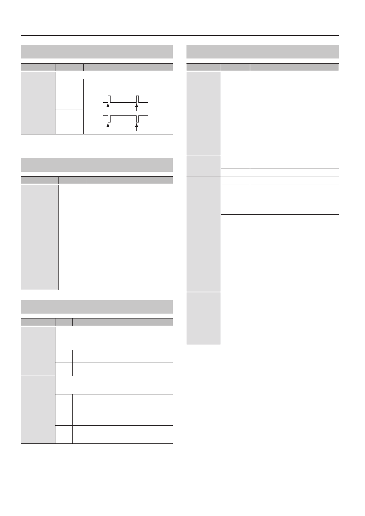
MENU
AMP CONTROL
Parameter Value Explanation
Species the operation of the AMP CTL 1, 2 jacks.
LATCH Latch operation
Send a pulse when changing patches.
AMP CTL1
AMP CTL2
* This is enabled when CTL 4, 5 SETTING is set to AMP CTL.
PULSE
INVERT
PULSE
Patch change Patch change
INVERT
Patch change Patch change
EXP HOLD
Parameter Value Explanation
OFF
EXP1 (EXP1 HOLD)
EXP2 (EXP2 HOLD)
ON
The operational status of the EXP PEDAL 1/2’s
FUNCTION (p. 33) is not carried over when
patches are switched.
If the EXP PEDAL 1/2’s FUNC (p. 33) are the
same between 2 patches, the operational
status is carried over when patches are
switched.
For example, if EXP PEDAL FUNCTION is set
to FOOT VOLUME in both patches, the one
before and the one after the change, the
volume corresponding to the position the
pedal is in (angle) at the time of the patch
change will be maintained after the patch
change. On the other hand, if the patch being
changed to is set to WAH, the volume will be
in accordance with the value set within the
patch, and you’ll obtain a wah eect that is
in accordance with a value that reects the
current position (angle) of the pedal.
GROUND LIFT
Parameter Value Explanation
In some cases, hum noise might occur if an amp or other
eect unit is connected. If so, you might be able to reduce
the noise by disconnecting the ground connector from the
MAIN
SUB
GT-1000CORE’s chassis.
The ground of the OUTPUT L, R jacks is connected to
GND
the chassis (no ground lift).
The ground of the OUTPUT jacks is disconnected from
LIFT
the chassis.
Species whether the ground of the SEND 1, 2 jacks and the
RETURN 1, 2 jacks are connected to the GT-1000CORE’s chassis
or disconnected.
The ground of the SEND 1, 2 jacks and the RETURN 1,
TYPE1
2 jacks is connected to the chassis (no ground lift).
The ground of the SEND 1 jack is disconnected from
TYPE2
the chassis, and the ground of the RETURN 1, 2 jacks is
connected to the chassis (no ground lift).
The ground of the SEND 1, 2 jacks is connected to the
TYPE3
chassis (no ground lift), and the ground of the RETURN
1, 2 jacks is disconnected from the chassis.
OTHER
Parameter Value Explanation
The GT-1000CORE can turn o its power automatically. The
power will turn o automatically when 10 hours have passed
since you last played or operated the unit. The display will show
a message approximately 15 minutes before the power turns
o.
With the factory settings, this function is turned “ON” (power-o
in 10 hours). If you want to have the power remain on all the
AUTO OFF
LCD CONTRAST
SEND1 SETTING,
SEND2 SETTING
CTL 4,5 SETTING
* When SEND1 SETTING and SEND2 SETTING are used as SEND and the sound
doesn’t seem right, change the SEND RETURN setting to TYPE 1.
time, turn it “OFF.”
* When the power is turned o, any settings you were editing
will be lost. You must save settings that you want to keep.
OFF The power will not turn o automatically.
ON
Here you can adjust the brightness of the characters in the
display.
1–10 Higher values increase the brightness.
This sets how the SEND and RETURN jacks are used.
SEND
SUB OUT
SUB OUT, AUX
MUTE
This sets how the CTL 4, 5/EXP 2 jack is used.
CTL IN
AMP CTL
The power will automatically turn o when
10 hours have passed since you last played or
operated the GT-1000CORE.
The jacks are used as SEND and RETURN jacks.
You can connect an external eects processor
between the SEND jack and RETURN jack, and
use it as one of the GT-1000CORE’s eects
processors.
The SEND jack is used as a SUB OUT jack.
You can send a signal separate from the
OUTPUT jack to a PA system or other
equipment.
In this case, the RETURN jack works as an AUX
IN jack. The input signal is output from the
OUTPUT jack along with the sound going
through the GT-1000CORE eects.
* Be aware that if a plug is not plugged into
the RETURN jack, the signal sent to SUB OUT
is also output to OUTPUT.
SUB OUT, AUX MUTE
Operates as the CTL 4, 5/EXP 2 jack.
You can control the various parameters by
plugging in a footswitch or expression pedal.
Operates as the AMP CLT 1, 2 jack.
If you connect this to the channel switch jack of
a guitar amp, you can use the GT-1000CORE to
switch channels.
* When SEND1 SETTING and SEND2 SETTING are used as SEND and the sound
doesn’t seem right, change the SEND RETURN setting to TYPE 1.
54
Page 55

FACTORY RESET
Initializes the GT-1000CORE to its factory-set condition.
Parameter Value Explanation
SYSTEM System parameter settings
FROM, TO
U001–U250
STOMPBOX Settings for STOMPBOX
Settings for Patch Numbers
U001–U250
TUNER
Here you can make settings for the TUNER.
Parameter Value Explanation
MODE (TUNER
MODE)
PITCH
OUTPUT
TYPE
OFFSET -5–-1, ---
NORMAL, STREAM
435–445 Hz (default:
440 Hz)
MUTE Sound will not be output while tuning.
BYPASS
THRU
6-REG (6-REGULAR),
6-DROP D,
7-REG (7-REGULAR),
7-DROP A,
4-B REG (4-B REGULAR),
5-B REG (5-B REGULAR)
Species the meter display method for
the monophonic tuner.
Species the reference pitch.
While tuning, the sound of the guitar
being input to the GT-1000CORE will
be output without change. All eects
will be o.
Allows you to tune while hearing the
current eect sound.
* Only for monophonic tuner.
Selects the type of tuning for the
polyphonic tuner.
Adjusts the reference pitch of the
polyphonic tuner in semitone units
relative to standard tuning.
MENU
METRONOME
Here you can make settings for the METRONOME.
* You can select the output destination of the metronome sound.
* By pressing knob 1 you can set the metronome’s BPM to the master
BPM value.
Parameter Value Explanation
BPM 20–250 Species the tempo.
BEAT
OFF/ON OFF, ON Turns the metronome on/o.
LEVEL 0–100 Adjusts the volume of the metronome sound.
1/1–8/1, 1/2–8/2,
1/4–8/4, 1/8–8/8
Selects the time signature.
55
Page 56

Saving a Sound (WRITE)
Saving a Patch (PATCH WRITE)
When you want to save a patch you have created, save it as a user
patch by following the procedure below. If you do not save the patch,
the edited settings will be lost when you turn o the power or switch
to another patch.
1. Press the [WRITE] button.
2. Press knob [1] to select “WRITE” (PATCH WRITE).
3. Use knob [1] to select the save-destination (U001–
U250).
You can use knobs [3]–[5] and [SELECT] knob to edit the name.
Exchanging Patches (PATCH EXCHANGE)
On the GT-1000CORE, you can “swap” or exchange the positions of
two User patches.
1. Select the exchange source patch.
2. Press the [WRITE] button.
3. Press knob [2] to select “EXCHANGE” (PATCH
EXCHANGE).
4. Use knob [1] to select the other user patch that you
want to exchange.
* If you decide to cancel without exchanging, press the [EXIT]
button a several times. You’ll be returned to the Play screen.
5. Press the [WRITE] button once again.
A conrmation message appears.
Editing a name
To edit the patch name, use knob [SELECT] to move the cursor
and use knob [5] to change the character.
Controller Operation
Turn the [3] knob Selects the type of characters
Press the [3] knob Delete one character (delete)
Turn the [4] knob Switch uppercase/lowercase
Press the [4] knob Insert one space (insert)
Turn the [5] knob Changes the character
Turn the [SELECT] knob Moves the cursor
4. Press the [WRITE] button once again.
The patch is written.
6. Press the [5] knob.
The patches will be exchanged. If you decide to cancel the
exchange operation, press knob [4].
56
Page 57

Saving a Sound (WRITE)
Initializing Patches (PATCH INITIALIZE)
You can return (initialize) a User patch to its original factory settings.
This is convenient when you want to create a new patch from scratch.
NOTE
Any tone settings you’ve stored in a patch are lost once the
initialization is executed.
1. Press the [WRITE] button.
2. Press knob [3] to select “INITIALIZE” (PATCH INITIALIZE).
3. Use knob [1] to select the user patch that you want
to initialize.
* If you decide to cancel without initializing, press the [EXIT] button
a several times. You’ll be returned to the Play screen.
4. Press the [WRITE] button once again.
A conrmation message appears.
Inserting a Patch (PATCH INSERT)
You can insert a patch into any position of the user patches.
For example, if you insert patch U001 at U002, patch U002 and
subsequent patches are shifted (renumbered) backward by one.
(Patch U002 becomes U003.)
NOTE
When you execute the insert operation, the last user patch (U250) is
deleted.
1. Press the [WRITE] button.
2. Press knob [4] to select “INSERT” (PATCH INSERT).
3. Use knob [1] to select the insert-destination user
patch.
* If you decide to cancel without inserting, press the [EXIT] button a
several times. You’ll be returned to the Play screen.
4. Press the [WRITE] button once again.
A conrmation message appears.
5. Press the [5] knob.
The patch will be initialized. If you decide to cancel the initialize
operation, press knob [4].
5. Press the [5] knob.
The patch is inserted at the specied position. If you decide to
choose the insert operation, press knob [4].
57
 Loading...