

Page 1
Parameter Guide
• Roland, BOSS, COSM, COMBO DRIVE, CRUNCH, FEEDBACKER,
HARMONIST, INTELLIGENT, METAL ZONE, OVERDRIVE, ROTARY SOUND,
SLICER, TOUCH WAH, Friend Jam, and BOSS Tone Central are either
registered trademarks or trademarks of Roland Corporation in the
United States and/or other countries.
• Company names and product names appearing in this document are
the registered trademarks or trademarks of their respective owners.
This document uses these names in order to appropriately describe the
sounds simulated by COSM technology.
Copyright © 2014 BOSS CORPORATION
All rights reserved. No part of this publication may be reproduced in any form without the written permission of BOSS CORPORATION.
01
Page 2
Contents
EFFECT . . . . . . . . . . . . . . . . . . . . . . . . . . . . . . . . . . . . . . . . . . . . . . . . . . . . . . . . . . 3
Editing the Eects. . . . . . . . . . . . . . . . . . . . . . . . . . . . . . . . . . . . . . . . . . . . . . . 3
COMP . . . . . . . . . . . . . . . . . . . . . . . . . . . . . . . . . . . . . . . . . . . . . . . . . . . . . . . . . .3
OD/DS . . . . . . . . . . . . . . . . . . . . . . . . . . . . . . . . . . . . . . . . . . . . . . . . . . . . . . . . . .3
PREAMP (PrA/PrB) . . . . . . . . . . . . . . . . . . . . . . . . . . . . . . . . . . . . . . . . . . . . . . . 4
EQ . . . . . . . . . . . . . . . . . . . . . . . . . . . . . . . . . . . . . . . . . . . . . . . . . . . . . . . . . . . . . . 7
FX1/FX2 . . . . . . . . . . . . . . . . . . . . . . . . . . . . . . . . . . . . . . . . . . . . . . . . . . . . . . . . 7
T. WAH . . . . . . . . . . . . . . . . . . . . . . . . . . . . . . . . . . . . . . . . . . . . . . . . . . . . 8
AUTO WAH. . . . . . . . . . . . . . . . . . . . . . . . . . . . . . . . . . . . . . . . . . . . . . . .8
SUB WAH . . . . . . . . . . . . . . . . . . . . . . . . . . . . . . . . . . . . . . . . . . . . . . . . .9
ADV. COMP . . . . . . . . . . . . . . . . . . . . . . . . . . . . . . . . . . . . . . . . . . . . . . .9
LIMITER . . . . . . . . . . . . . . . . . . . . . . . . . . . . . . . . . . . . . . . . . . . . . . . . . . . 9
SUB OD/DS . . . . . . . . . . . . . . . . . . . . . . . . . . . . . . . . . . . . . . . . . . . . . .10
GRAPHIC EQ . . . . . . . . . . . . . . . . . . . . . . . . . . . . . . . . . . . . . . . . . . . . .10
PARAMETRIC EQ . . . . . . . . . . . . . . . . . . . . . . . . . . . . . . . . . . . . . . . . .10
TONE MODIFY . . . . . . . . . . . . . . . . . . . . . . . . . . . . . . . . . . . . . . . . . . .10
GUITAR SIM . . . . . . . . . . . . . . . . . . . . . . . . . . . . . . . . . . . . . . . . . . . . . .11
AC. GUITAR SIM . . . . . . . . . . . . . . . . . . . . . . . . . . . . . . . . . . . . . . . . . .11
SLOW GEAR . . . . . . . . . . . . . . . . . . . . . . . . . . . . . . . . . . . . . . . . . . . . . .11
DEFRETTER . . . . . . . . . . . . . . . . . . . . . . . . . . . . . . . . . . . . . . . . . . . . . .11
WAVE SYNTH . . . . . . . . . . . . . . . . . . . . . . . . . . . . . . . . . . . . . . . . . . . . .11
SITAR SIM. . . . . . . . . . . . . . . . . . . . . . . . . . . . . . . . . . . . . . . . . . . . . . . .12
OCTAVE . . . . . . . . . . . . . . . . . . . . . . . . . . . . . . . . . . . . . . . . . . . . . . . . . .12
PITCH SHIFTER . . . . . . . . . . . . . . . . . . . . . . . . . . . . . . . . . . . . . . . . . . .12
HARMONIST . . . . . . . . . . . . . . . . . . . . . . . . . . . . . . . . . . . . . . . . . . . . .13
OVERTONE (FX2 Only) . . . . . . . . . . . . . . . . . . . . . . . . . . . . . . . . . . . .13
SOUND HOLD . . . . . . . . . . . . . . . . . . . . . . . . . . . . . . . . . . . . . . . . . . . .13
AC. PROCESSOR . . . . . . . . . . . . . . . . . . . . . . . . . . . . . . . . . . . . . . . . . .14
PHASER . . . . . . . . . . . . . . . . . . . . . . . . . . . . . . . . . . . . . . . . . . . . . . . . . .14
FLANGER . . . . . . . . . . . . . . . . . . . . . . . . . . . . . . . . . . . . . . . . . . . . . . . .14
TREMOLO . . . . . . . . . . . . . . . . . . . . . . . . . . . . . . . . . . . . . . . . . . . . . . . .15
ROTARY 1/ROTARY 2 . . . . . . . . . . . . . . . . . . . . . . . . . . . . . . . . . . . . .15
UNI-V . . . . . . . . . . . . . . . . . . . . . . . . . . . . . . . . . . . . . . . . . . . . . . . . . . . .15
PAN . . . . . . . . . . . . . . . . . . . . . . . . . . . . . . . . . . . . . . . . . . . . . . . . . . . . .15
SLICER . . . . . . . . . . . . . . . . . . . . . . . . . . . . . . . . . . . . . . . . . . . . . . . . . . .16
VIBRATO . . . . . . . . . . . . . . . . . . . . . . . . . . . . . . . . . . . . . . . . . . . . . . . . .16
RING MOD . . . . . . . . . . . . . . . . . . . . . . . . . . . . . . . . . . . . . . . . . . . . . . .16
HUMANIZER . . . . . . . . . . . . . . . . . . . . . . . . . . . . . . . . . . . . . . . . . . . . .16
2X2 CHORUS . . . . . . . . . . . . . . . . . . . . . . . . . . . . . . . . . . . . . . . . . . . . .17
SUB DELAY . . . . . . . . . . . . . . . . . . . . . . . . . . . . . . . . . . . . . . . . . . . . . . .17
TERA ECHO (FX2 Only) . . . . . . . . . . . . . . . . . . . . . . . . . . . . . . . . . . .17
DELAY . . . . . . . . . . . . . . . . . . . . . . . . . . . . . . . . . . . . . . . . . . . . . . . . . . . . . . . . .18
CHORUS . . . . . . . . . . . . . . . . . . . . . . . . . . . . . . . . . . . . . . . . . . . . . . . . . . . . . . .19
REVERB . . . . . . . . . . . . . . . . . . . . . . . . . . . . . . . . . . . . . . . . . . . . . . . . . . . . . . . .20
PEDAL FX . . . . . . . . . . . . . . . . . . . . . . . . . . . . . . . . . . . . . . . . . . . . . . . . . . . . . .20
PEDAL BEND . . . . . . . . . . . . . . . . . . . . . . . . . . . . . . . . . . . . . . . . . . . . .20
WAH . . . . . . . . . . . . . . . . . . . . . . . . . . . . . . . . . . . . . . . . . . . . . . . . . . . . .20
FOOT VOLUME . . . . . . . . . . . . . . . . . . . . . . . . . . . . . . . . . . . . . . . . . . . . . . . . .21
FOOT VOLUME . . . . . . . . . . . . . . . . . . . . . . . . . . . . . . . . . . . . . . . . . . .21
DIVIDER . . . . . . . . . . . . . . . . . . . . . . . . . . . . . . . . . . . . . . . . . . . . . . . . . . . . . . .21
SINGLE . . . . . . . . . . . . . . . . . . . . . . . . . . . . . . . . . . . . . . . . . . . . . . . . . .21
DUAL Ch. A, DUAL Ch. B . . . . . . . . . . . . . . . . . . . . . . . . . . . . . . . . . .21
MIXER . . . . . . . . . . . . . . . . . . . . . . . . . . . . . . . . . . . . . . . . . . . . . . . . . . . . . . . . .22
NS1/NS2 . . . . . . . . . . . . . . . . . . . . . . . . . . . . . . . . . . . . . . . . . . . . . . . . . . . . . . .22
ACCEL FX . . . . . . . . . . . . . . . . . . . . . . . . . . . . . . . . . . . . . . . . . . . . . . . . . . . . . .22
S-BEND . . . . . . . . . . . . . . . . . . . . . . . . . . . . . . . . . . . . . . . . . . . . . . . . . .22
LASER BEAM . . . . . . . . . . . . . . . . . . . . . . . . . . . . . . . . . . . . . . . . . . . . .22
RING MOD . . . . . . . . . . . . . . . . . . . . . . . . . . . . . . . . . . . . . . . . . . . . . . .23
TWIST . . . . . . . . . . . . . . . . . . . . . . . . . . . . . . . . . . . . . . . . . . . . . . . . . . .23
WARP . . . . . . . . . . . . . . . . . . . . . . . . . . . . . . . . . . . . . . . . . . . . . . . . . . . .23
FEEDBACKER . . . . . . . . . . . . . . . . . . . . . . . . . . . . . . . . . . . . . . . . . . . . .23
MASTER SETTING . . . . . . . . . . . . . . . . . . . . . . . . . . . . . . . . . . . . . . . . . . . . . .24
MASTER SETTING . . . . . . . . . . . . . . . . . . . . . . . . . . . . . . . . . . . . . . . .24
MASTER EQ . . . . . . . . . . . . . . . . . . . . . . . . . . . . . . . . . . . . . . . . . . . . . .24
MENU . . . . . . . . . . . . . . . . . . . . . . . . . . . . . . . . . . . . . . . . . . . . . . . . . . . . . . . . . .25
CTL/EXP . . . . . . . . . . . . . . . . . . . . . . . . . . . . . . . . . . . . . . . . . . . . . . . . . . . . . . .25
Pedal Settings . . . . . . . . . . . . . . . . . . . . . . . . . . . . . . . . . . . . . . . . . . .25
Using a Pedal to Control Desired Parameters . . . . . . . . . . . . . .25
CTL1, CTL2 . . . . . . . . . . . . . . . . . . . . . . . . . . . . . . . . . . . . . . . . . . . . . . .25
EXP . . . . . . . . . . . . . . . . . . . . . . . . . . . . . . . . . . . . . . . . . . . . . . . . . . . . . .26
Specifying the External Pedal Function for Each Patch
(Assign) . . . . . . . . . . . . . . . . . . . . . . . . . . . . . . . . . . . . . . . . . . . . . . . . . .26
ASSIGN COMMON. . . . . . . . . . . . . . . . . . . . . . . . . . . . . . . . . . . . . . . .26
ASSIGN 1–8 . . . . . . . . . . . . . . . . . . . . . . . . . . . . . . . . . . . . . . . . . . . . . .26
Virtual expression pedal system (Internal Pedal / Wave
Pedal) . . . . . . . . . . . . . . . . . . . . . . . . . . . . . . . . . . . . . . . . . . . . . . . . . . .31
Input level . . . . . . . . . . . . . . . . . . . . . . . . . . . . . . . . . . . . . . . . . . . . . . .31
SYSTEM . . . . . . . . . . . . . . . . . . . . . . . . . . . . . . . . . . . . . . . . . . . . . . . . . . . . . . . .33
OUTPUT SELECT . . . . . . . . . . . . . . . . . . . . . . . . . . . . . . . . . . . . . . . . .33
INPUT . . . . . . . . . . . . . . . . . . . . . . . . . . . . . . . . . . . . . . . . . . . . . . . . . . .33
KNOB SETTING . . . . . . . . . . . . . . . . . . . . . . . . . . . . . . . . . . . . . . . . . . .33
USB . . . . . . . . . . . . . . . . . . . . . . . . . . . . . . . . . . . . . . . . . . . . . . . . . . . . . .34
GLOBAL EQ . . . . . . . . . . . . . . . . . . . . . . . . . . . . . . . . . . . . . . . . . . . . . .34
TOTAL . . . . . . . . . . . . . . . . . . . . . . . . . . . . . . . . . . . . . . . . . . . . . . . . . . .35
PLAY OPTION . . . . . . . . . . . . . . . . . . . . . . . . . . . . . . . . . . . . . . . . . . . .35
PREFERENCE . . . . . . . . . . . . . . . . . . . . . . . . . . . . . . . . . . . . . . . . . . . . .35
LCD . . . . . . . . . . . . . . . . . . . . . . . . . . . . . . . . . . . . . . . . . . . . . . . . . . . . . .35
G.2MIDI (GUITAR TO MIDI) . . . . . . . . . . . . . . . . . . . . . . . . . . . . . . . .35
MIDI SETTING . . . . . . . . . . . . . . . . . . . . . . . . . . . . . . . . . . . . . . . . . . . .36
P.MAP (MIDI-PROGRAM CHG MAP) . . . . . . . . . . . . . . . . . . . . . . . .37
MIDI BULK DUMP . . . . . . . . . . . . . . . . . . . . . . . . . . . . . . . . . . . . . . . .37
AUTO OFF . . . . . . . . . . . . . . . . . . . . . . . . . . . . . . . . . . . . . . . . . . . . . . .37
FACTORY RESET . . . . . . . . . . . . . . . . . . . . . . . . . . . . . . . . . . . . . . . . . .37
DAW CTL (DAW Control) . . . . . . . . . . . . . . . . . . . . . . . . . . . . . . . . . . . . . . . .38
Other Settings . . . . . . . . . . . . . . . . . . . . . . . . . . . . . . . . . . . . . . . . . . . . . . . . . . 39
TUNER/METRONOME . . . . . . . . . . . . . . . . . . . . . . . . . . . . . . . . . . . . . . . . . .39
TUNER . . . . . . . . . . . . . . . . . . . . . . . . . . . . . . . . . . . . . . . . . . . . . . . . . . .39
METRONOME . . . . . . . . . . . . . . . . . . . . . . . . . . . . . . . . . . . . . . . . . . . .39
Troubleshooting . . . . . . . . . . . . . . . . . . . . . . . . . . . . . . . . . . . . . . . . . . . . . . . .40
Preset Patch List . . . . . . . . . . . . . . . . . . . . . . . . . . . . . . . . . . . . . . . . . . . . . . . .41
2
MEMO
•
This eect sound is mono.
•
This eect sound is output with two channels.
These eects take a mono input and output it on two channels.
•
Page 3
EFFECT
Editing the Eects
To edit the eect settings, use the value knob to select a page in the
display, and use knobs [1]–[4] to select the value of each parameter.
MEMO
• For details on basic operation for eects, refer to “Editing:
Editing the Eects” (p. 7) in the owner’s manual.
• In each edit screen, you can press the value knob to turn the
eect on/o.
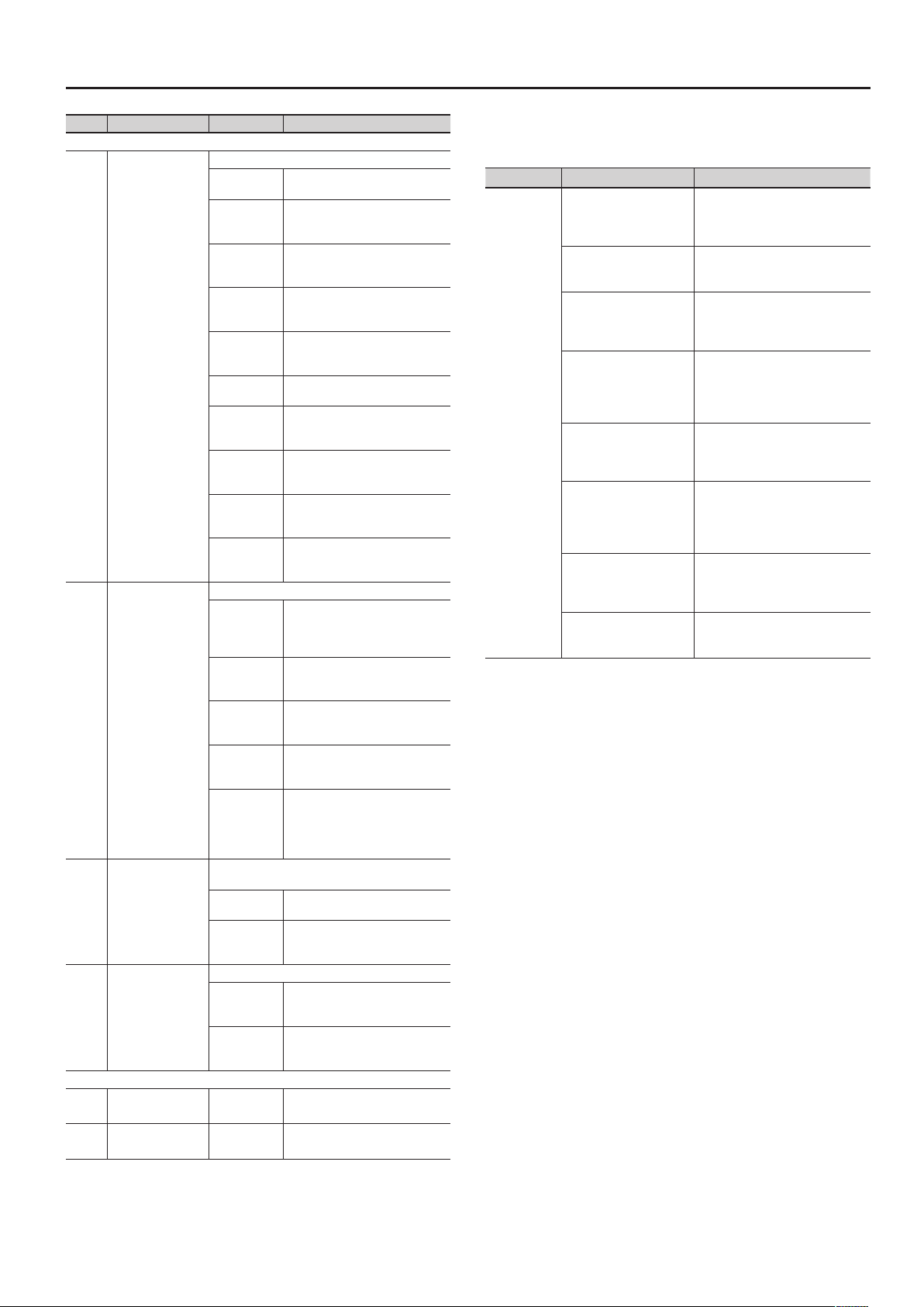
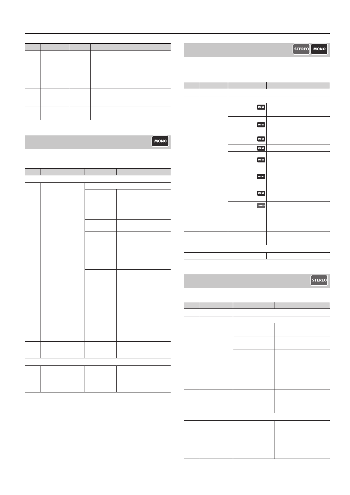
COMP
This is an eect that produces a long sustain by evening out the
volume level of the input signal.
Knob Parameter Value Explanation
ON/OFF OFF, ON Turns this eect on/o.
Page 1
BOSS
(BOSS COMP)
HI-BAND
LIGHT
D-COMP This models a MXR DynaComp.
[1] TYPE
[2] SUSTAIN 0–100
[3] ATTACK 0–100
[4] LEVEL 0–100 Adjusts the volume.
Page 2
[1] TONE -50–+50 This adjusts the tone.
ORANGE
FAT
MILD
STEREO
(STEREO COMP)
This models a BOSS CS-3.
This is a compressor that adds
an even stronger eect in the
high end.
This is a compressor with a light
eect.
This is modeled on the sound
of the Dan Armstrong ORANGE
SQUEEZER.
When applied heavily, this
compressor eect provides a fat
tone with a boosted midrange.
When applied heavily, this
compressor eect produces a
sweet tone with the high end
cut.
This selects a stereo compressor.
Adjusts the range (time) over
which low-level signals are
boosted. Larger values will
result in longer sustain.
Adjusts the strength of the
picking attack when the strings
are played. Higher values result
in s sharper attack, creating a
more clearly dened sound.
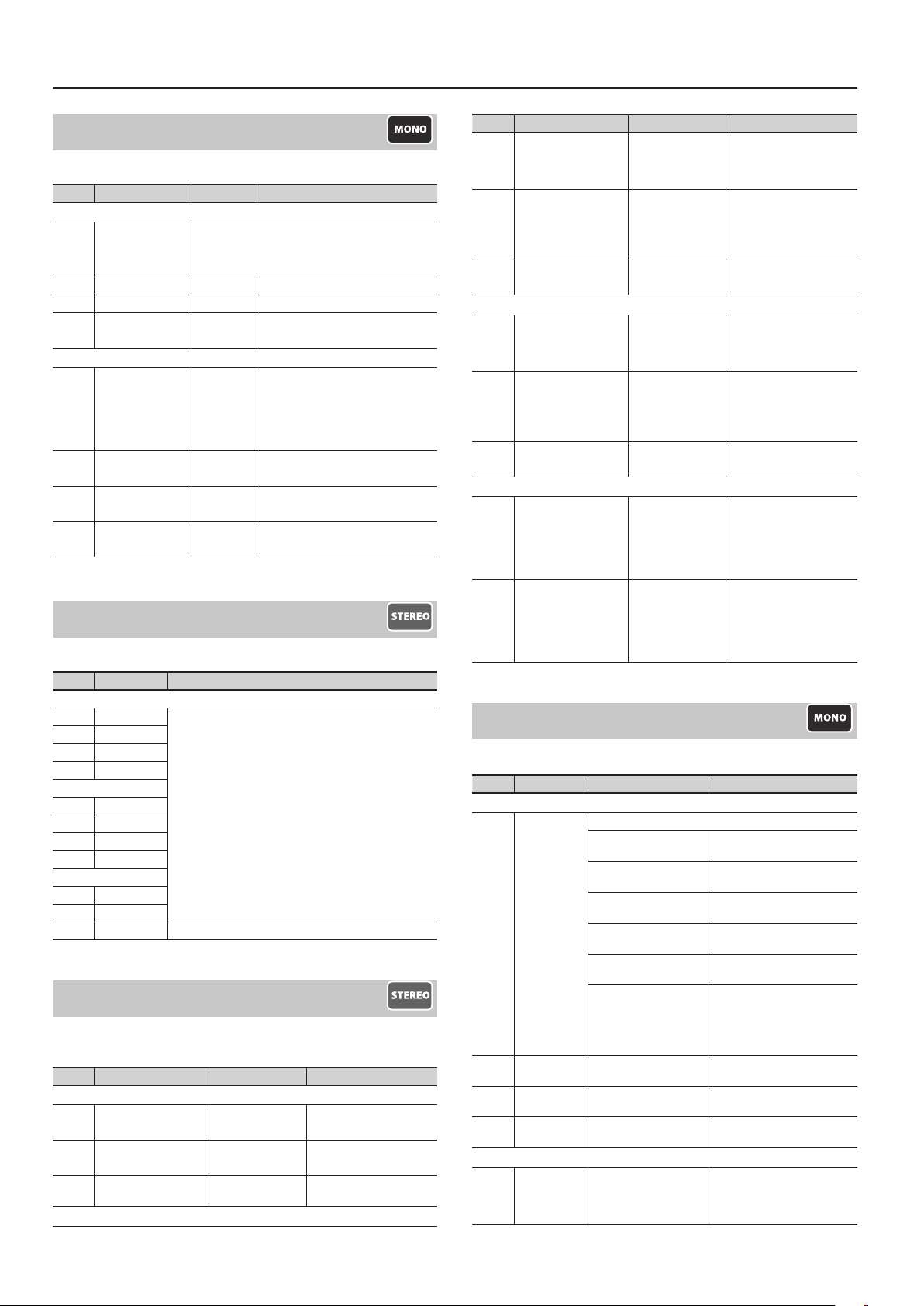
OD/DS
This eect distorts the sound to create long sustain.
Knob Parameter Value Explanation
ON/OFF OFF, ON Turns this eect on/o.
Page 1
[1] TYPE Refer to OD/DS TYPE
[2] DRIVE 0–120 Adjusts the depth of distortion.
[3] TONE -50–+50 This adjusts the tone.
E.LEVEL
[4]
(EFFECT LEVEL)
Page 2
[1] BOTTOM -50–+50
DIR.MIX
[2]
(DIRECT MIX)
SOL.SW
[3]
(SOLO SW)
SOL.LV
[4]
(SOLO LEVEL)
0–100
0–100
OFF, ON
0–100
OD/DS TYPE
This is a list of distortion types that can be selected for OD/DS.
Category Type Explanation
MID BST
(MID BOOST)
CLN BST
(CLEAN BOOST)
TRB BST
(TREBLE BOOST)
CRUNCH
NTRL OD
(NATURAL OD)
ADVANCED
WRM OD (WARM
OD)
FAT DS A distortion sound with thick distortion.
LEAD DS
METL DS
(METAL DS)
OCT FUZ
(OCT FUZZ)
A-DIST
* Only for OD/DS
and SUB OD/DS
in FX2
Adjusts the volume of the eect
sound.
Adjusts the tone for the low
frequency range. Turning this to the
left (counterclockwise) produces a
sound with the low end cut; turning
it to the right boosts the low end in
the sound.
Adjusts the volume of the direct
sound.
Switches to a tone that is suitable
for solos.
Adjusts the volume level when the
Solo Sw is ON.
This is a booster with unique characteristics
in the midrange.
Making the connection before the COSM
amp produces sound suitable for solos.
This not only functions as a booster, but
also produces a clean tone that has punch
even when used alone.
This is a booster that has bright
characteristics.
A lustrous crunch sound with an added
element of amp distortion.
This is an overdrive sound that provides
distortion with a natural feeling.
This is a warm overdrive.
Produces a distortion sound with both the
smoothness of an overdrive along with a
deep distortion.
This is distortion sound that is ideal for
performances of heavy ris.
A fuzz sound with rich harmonic content.
This eect uses MDP (Multi-Dimensional
Processing) to provide ideal distortion in all
pitch ranges of the guitar, from low to high.
3
Page 4
EFFECT
Category Type Explanation
This is a crunch sound of the BOSS BD-2.
This produces distortion that faithfully
reproduces the nuances of picking.
This models the sound of the BOSS OD-1.
This produces sweet, mild distortion.
This models an Ibanez TS-808.
This is the high-gain overdrive sound of the
BOSS OD-2.
This gives a basic, traditional distortion
sound.
This models the sound of the BOSS MT-2.
It produces a wide range of metal sounds,
from old style to slash metal.
This models a FUZZFACE.
It produces a fat fuzz sound.
This models an Electro-Harmonix Big
Mu π.
Custom OD/DS
You can customize it however you like to
match the sound you want.
VINTAGE
CUSTOM
BLUS OD
(BLUES OD)
OD-1
T-SCRM
(T-SCREAM)
TURB OD
(TURBO OD)
DIST
(DISTORTION)
RAT This models a Proco RAT.
GUV DS This models a Marshall GUV’NOR.
DST+ This models a MXR DISTORTION+.
MTL ZON
(METAL ZONE)
60S FUZ
('60S FUZZ)
MUF FUZ
(MUFF FUZZ)
CUSTOM OD/DS SETTING
Knob Parameter Value Explanation
Page 3 (shown only if OD/DS TYPE is set to “CUSTOM”)
OD-1
OD-2
CRUNCH This is a crunch sound.
TYPE
[1]
(CUSTOM TYPE)
CHAR
[2]
(CUSTOM CHARACTER)
BOTTOM
[3]
(CUSTOM BOTTOM)
TOP
[4]
(CUSTOM TOP)
Page 4 (shown only if OD/DS TYPE is set to “CUSTOM”)
[1] LOW (CUSTOM LOW) -50–+50
[2] HIGH (CUSTOM HIGH) -50–+50
DS-1
DS-2
METAL1
METAL2
FUZZ
-50–+50
-50–+50
-50–+50
This models the sound of
the BOSS OD-1.
This is a overdrive sound
with high gain.
This gives a basic,
traditional distortion
sound.
This creates a heavier
distortion sound.
This is a metal sound with a
characteristic midrange.
This gives a heavy metal
sound.
This gives a basic,
traditional fuzz sound.
+: For soloing
-: For backing
This controls the input
sound’s low-frequency
range and adjusts the
amount of distortion in the
low-frequency range
This controls the input
sound’s high-frequency
range and adjusts the
amount of distortion in the
high-frequency range.
Adjusts the low-range
tones after distortion is
applied.
Adjusts the high-range
tones after distortion is
applied.
PREAMP (PrA/PrB)
COSM technology simulates dierent preamp characteristics,
speaker sizes, and cabinet shapes.
Knob Parameter Value Explanation
ON/OFF OFF, ON Turns this eect on/o.
Page 1
[1] TYPE Refer to PREAMP TYPE
[2] GAIN 0–120 Adjusts the distortion of the amp.
[3] T-COMP -10–0–+10
[4] LEVEL 0–100
Page 2
[1] BASS 0–100
[2] MIDDLE 0–100
[3] TREBLE 0–100
[4] PRES (PRESENCE) 0–100
Page 3
[1] BRIGHT OFF, ON
[2] GAIN.SW
SOL.SW
[3]
(SOLO SW)
SOL.LV
[4]
(SOLO LEVEL)
LOW, MIDDLE,
HIGH
OFF, ON The tone to one suitable for solos.
0–100
Adjusts the sense of compression
of the amp.
Adjusts the volume of the entire
preamp.
* Be careful not to raise the Level
setting too high.
Adjusts the tone for the low
frequency range.
Adjusts the tone for the middle
frequency range.
Adjusts the tone for the high
frequency range.
Adjusts the tone for the ultra high
frequency range.
* The PRESENCE parameter
functions as a high-cut lter with
some PREAMP TYPEs.
Turns the bright setting on/o.
* The BRIGHT parameter setting
is available only with certain
PREAMP TYPEs.
Switches the amp’s amount of
distortion in three steps: LOW,
MIDDLE, and HIGH. The steps
LOW, MIDDLE, and HIGH provide
correspondingly increasing
amounts of distortion.
* The sound of each Type is
created on the basis that the
Gain is set to MIDDLE.
Adjusts the volume level when the
Solo Sw is ON.
4
Page 5
EFFECT
Knob Parameter Value Explanation
Page 4
Select the speaker type.
This turns o the speaker
simulator.
This is the built-in speaker of the
amp you selected with PREAMP
TYPE.
This is a compact open-back
speaker cabinet with one 8-inch
speaker.
This is a compact open-back
speaker cabinet with one 10-inch
speaker.
This is a compact open-back
speaker cabinet with one 12-inch
speaker.
This is a general open-back speaker
cabinet with two 12-inch speakers.
This is an optimal speaker cabinet
for a large enclosed amp with four
10-inch speakers.
This is an optimal speaker cabinet
for a large enclosed amp with four
12-inch speakers.
This is a double stack of two
cabinets, each with four 12-inch
speakers.
Custom speaker You can customize
it however you like to match the
sound you want.
This is the sound of the SHURE SM-
57. General dynamic mic used for
instruments and vocals. Optimal
for use in miking guitar amps.
Simulates the sound of the MD-
421. Dynamic mic with extended
low end.
Simulates the sound of the AKG
C451B. Small condenser mic for use
with instruments.
Simulates the sound of the
NEUMANN U87. Condenser mic
with at response.
Simulates a mic with perfectly at
response. Produces a sonic image
close to that of listening to the
sound directly from the speakers
(on site).
This setting points the mic away
from the speaker.
Provides conditions whereby the
mic is directed more towards the
speaker.
Simulates the condition that the
mic is set in the middle of the
speaker cone.
Simulates the condition that the
mic is moved away from the center
of the speaker cone.
Adjusts the volume of the direct
sound.
[1]
[2]
[3]
[4]
Page 5
[1]
[2]
SP.TYP
(SPEAKER TYPE)
*1
MIC.TYP
(MIC TYPE)
*1
MIC.DIS
(MIC DISTANCE)
*1
MIC.POS
(MIC POSITION)
*1
MIC.LVL
(MIC LEVEL) *1
DIR.MIX
(DIRECT MIX) *1
OFF
ORIGIN
(ORIGINAL)
1x8"
1x10"
1x12"
2x12"
4x10"
4x12"
8x12"
CUSTOM
This setting selects the simulated mic type.
DYN57
DYN421
CND451
CND87
FLAT
Simulates the distance between the mic and
speaker.
OFF MIC
ON MIC
This simulates the mic position.
CENTER
1–10 cm
0–100 Adjusts the volume of the mic.
0–100
PREAMP TYPE
This is a list of the amp types that can be selected for PREAMP.
Category Type Explanation
NtrlCLN
(NATURAL CLEAN)
FUL RNG
(FULL RANGE)
CB CRNC
(COMBO CRUNCH)
ST CRNC
(STACK CRUNCH)
ADVANCED
HiG STK
(HiGAIN STACK)
PwrDRV
(POWER DRIVE)
XTRM LD
(EXTREME LEAD)
COR MTL
(CORE METAL)
An unembellished, clean sound that
minimizes the amp’s idiosyncrasies,
such as its trebly character and
boomy low end.
An amp with a broad frequency
range and an extremely at response. Good for acoustic guitar.
Crunch sound that allows the
nuances of your picking to be
expressed even more faithfully than
on conventional combo amps.
Great-feeling crunch sound that
responds well to picking dynamics
while retaining all the dening
characteristics of a 4 x 12” speaker
cabinet.
High-gain sound of a vintage
Marshall specially revamped in a
way that is possible only with COSM
modeling technology.
A straightforward drive sound
that is suitable for a wide range of
situations from backing to lead, and
which could not be obtained from
previous combo amps or stack amps.
A new type of sound that smoothes
out the uneven frequency response
that is typical of existing large stack
amps.
A large stack sound that has been
tweaked extensively in the pursuit of
the ultimate metal sound.
*1 This is enabled when the OUTPUT SELECT parameter is set to LINE/PHONE.
5
Page 6
EFFECT
Category Type Explanation
This models the sound of the Roland
JC-120.
This models a Fender Twin Reverb.
This models a Fender Pro Reverb.
This models a Fender Bassman 4 x
10” Combo.
This models a Fender Deluxe Reverb.
This models the drive sound of a VOX
AC-30TB.
This is a sound that it suited to
sixties-style British rock.
This models the lead sound of the
VOX AC-30TB.
This models the sound input to left
input on a Matchless D/C-30.
A simulation of the latest tube amp
widely used in styles from blues and
rock.
This models the lead sound of the
MESA/ Boogie combo amp.
The sound of a tube amp typical of
the late ’70s to ’80s.
This models a MESA/Boogie with
TREBLE SHIFT SW on.
This models the sound input to Input
I on a Marshall 1959.
This is a trebly sound suited to hard
rock.
This models the sound of a Marshal
1959’s inputs I and II connected in
parallel. The sound emphasizes the
low end more than I.
Models the sound of the Channel 2
VINTAGE Mode on the MESA/Boogie
DUAL Rectier.
Models the sound of the Channel 2
MODERN Mode on the MESA/Boogie
DUAL Rectier.
This models a Hughes & Kettner
Triamp AMP3.
This models a Soldano SLO-100. This
is the typical sound of the eighties.
This models the lead channel of a
Peavey EVH 5150.
This is a heavily distorted sound that
models the high gain channel of a
Bogner Uberschall.
This models the dirty channel of an
ORANGE ROCKERVERB.
This is a custom preamp.
You can customize it however you
like to match the sound you want.
VINTAGE
CUSTOM
JC-120
CLN TWN
(CLEAN TWIN)
PR CRNC
(PRO CRUNCH)
TWEED
DxCRNC
(DELUXE CRUNCH)
VO DRIV
(VO DRIVE)
VO LEAD
MATCH
(MATCH DRIVE)
BG LEAD
BG DRIV
(BG DRIVE)
1959 I
(MS1959 I)
1959 I+II
(MS1959 I+II)
RFR VIN
(R-FIER VINTAGE)
RFR MDN
(R-FIER MODERN)
T-AMP
(T-AMP LEAD)
SLDN
5150
(5150 DRIVE)
BGNR UB
(BGNR UB METAL)
ORNG RV
(ORNG ROCK REVERB)
CUSTOM AMP SETTING
Knob Parameter Value Explanation
Page 6 (shown only if PREAMP TYPE is set to “CUSTOM”)
JC CLEN
(JC CLEAN)
TW CLEN
(TW CLEAN)
CRUNCH
CMB DRV
TYPE
[1]
(CUSTOM TYPE)
CHAR
[2]
(CUSTOM
CHARACTER)
BOTTOM
[3]
(CUSTOM BOTTOM)
EDGE (CUSTOM
[4]
EDGE)
Page 7 (shown only if PREAMP TYPE is set to “CUSTOM”)
LOW
[1]
(CUSTOM PREAMP
LOW)
HIGH
[2]
(CUSTOM PREAMP
HIGH)
(COMBO DRIVE)
CMB LD
(COMBO LEAD)
MS HiG
(MS HiGAIN)
MDN STK
(MODERN
STACK)
-50–+50
-50–+50
-50–+50
-50–+50
-50–+50
This models the sound of the
Roland JC-120.
This models a Fender Twin Reverb.
This is a crunch sound that can
faithfully reproduce the nuances
of picking.
This is a combo amp sound that it
suited to sixties-style British rock.
This is a lead sound of a combo
tube amp typical of the late ’70s
to ’80s.
This models the sound input to
Input I on a Marshall 1959.
This is a trebly sound suited to
hard rock.
This original high-gain amp
delivers thick lows and intense
distortion while still preserving
the sound’s clear denition.
+: For soloing
-: For backing
This controls the input sound’s
low-frequency range and adjusts
the amount of distortion in the
low-frequency range
This controls the input sound’s
high-frequency range and adjusts
the amount of distortion in the
high-frequency range.
Adjusts the preamp section’s
low-frequency tone.
Adjusts the preamp section’s
high-frequency tone.
CUSTOM SPEAKER SETTING
Knob Parameter Value Explanation
Page 8 (shown only if SPEAKER TYPE is set to “CUSTOM”)
SP.SIZE
[1]
(CUSTOM SPEAKER SIZE)
SP.NUM
[2]
(CUSTOM SPEAKER NUMBER)
CABINET
[3]
(CUSTOM CABINET)
Page 9 (shown only if SPEAKER TYPE is set to “CUSTOM”)
COLOR.L
[1]
(CUSTOM COLOR LOW)
COLOR.H
[2]
(CUSTOM COLOR HIGH)
5–15" Selects the size of speaker.
x1, x2, x4, x8
Selects the speaker cabinet type.
OPEN
CLOSE
-10–+10
-10–+10
Sets the number of
speakers.
This is an open-backed
cabinet
This type of cabinet
features an enclosed rear
panel.
Adjusts the speaker
section’s low-frequency
tone.
Adjusts the speaker
section’s high-frequency
tone.
6
Page 7
EFFECT
EQ
This adjusts the tone. A parametric type is adopted for the highmiddle and low-middle range.
Knob Parameter Value Explanation
ON/OFF OFF, ON Turns this eect on/o.
Page 1
LO.GAIN
[1]
(LOW GAIN)
HI.GAIN
[2]
(HIGH GAIN)
[4] LEVEL -20–+20 dB
Page 2
LM.FREQ
[1]
(LOW-MID
FREQUENCY)
LM.Q
[2]
(LOW-MID Q)
LM.GAIN
[3]
(LOW-MID GAIN)
Page 3
HM.FREQ
[1]
(HIGH-MID
FREQUENCY)
HM.Q
[2]
(HIGH-MID Q)
HM.GAIN
[3]
(HIGH-MID GAIN)
Page 4
LO.CUT
[1]
(LOW CUT)
HI.CUT
[4]
(HIGH CUT)
-20–+20 dB
-20–+20 dB
20 Hz–10.0 kHz
0.5–16
-20–+20 dB
20 Hz–10.0 kHz
0.5–16
-20–+20 dB
FLAT, 20
Hz–800 Hz
630 Hz–
12.5 kHz, FLAT
Adjusts the low frequency range
tone.
Adjusts the high frequency range
tone.
Adjusts the overall volume level
of the equalizer.
Species the center of the
frequency range that will be
adjusted by the LOW-MID GAIN.
Adjusts the width of the area
aected by the EQ centered
at the LOW-MID FREQ. Higher
values will narrow the area.
Adjusts the middle frequency
range tone.
Species the center of the
frequency range that will be
adjusted by the HIGH-MID GAIN.
Adjusts the width of the area
aected by the EQ centered
at the HIGH-MID FREQ. Higher
values will narrow the area.
Adjusts the low-middle
frequency range tone.
This sets the frequency at which
the low cut lter begins to take
eect. When “Flat” is selected, the
low cut lter will have no eect.
This sets the frequency at which
the high cut lter begins to take
eect. When “FLAT” is selected,
the high cut lter will have no
eect.
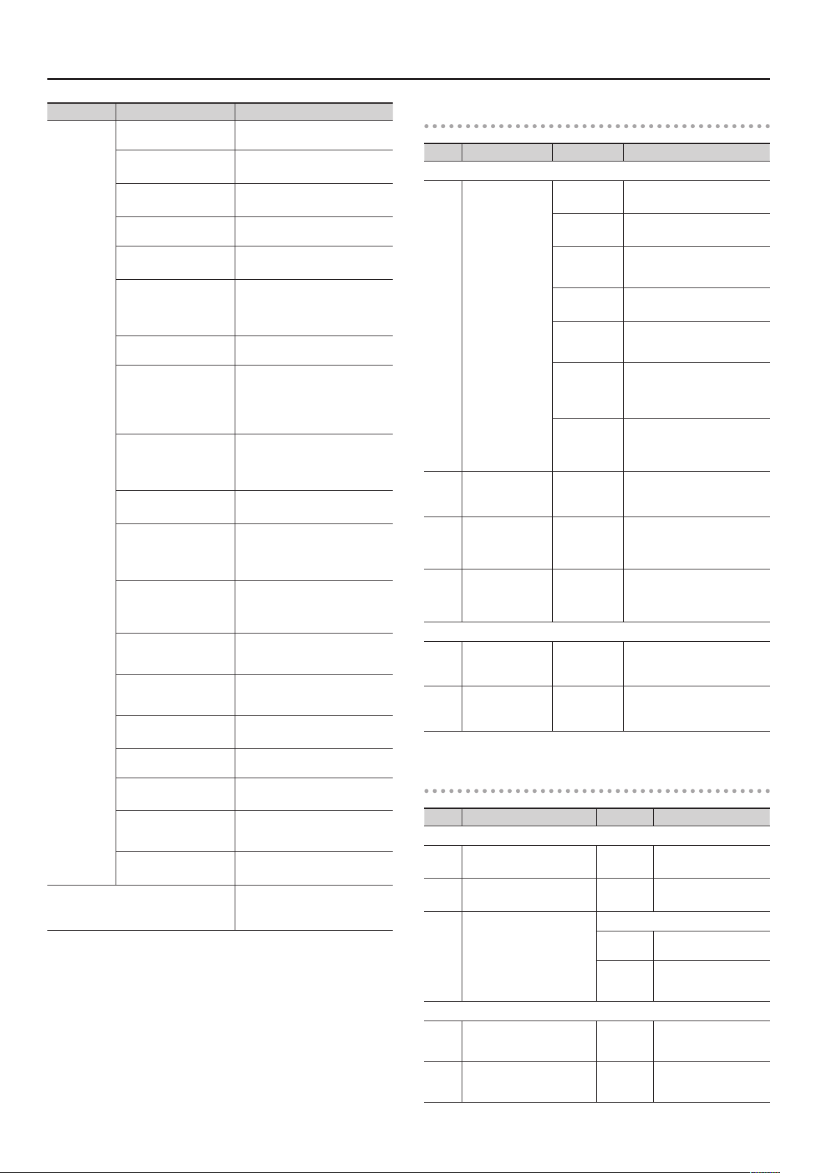
FX1/FX2
With FX1 and FX2, you can select the eect to be used from the
following. You can select the same eect for FX1 and FX2.
* Some eects can be selected only for FX2.
Parameter Value Explanation
ON/OFF OFF, ON Turns this eect on/o.
TYPE Refer to FX1/FX2 TYPE
Selecting the TYPE
1. Choose [EFFECT]"”FX1” or “FX2.”
2. Select the type using the knob [4].
FX1/FX2 TYPE
This is a list of the eects that can be selected for FX1/FX2.
Eect Name TYPE Explanation
T. WAH ( Touch Wah)
AUTO WAH (Auto Wah)
SUB WAH —
ADV. COMP
LIMITER —
SUB OD/DS —
GRAPHIC EQ
PARAMETRIC EQ
TONE MODIFY —
GUITAR SIM
AC.GUITAR SIM —
SLOW GEAR —
DEFRETTER — This simulates a fretless guitar.
WAVE SYNTH —
SITAR SIM (Sitar Simulator) This simulates the sound of the sitar.
OCTAVE —
PITCH SHIFTER —
(Advanced
Compressor)
(Graphic
Equalizer)
(Parametric
Equalizer)
(Guitar
Simulator)
You can produce a wah eect with the
lter changing in response to the guitar
level.
This changes the ltering over a periodic
cycle, providing an automatic wah eect.
You can use an expression pedal
connected to the CTL/EXP jack to control
the wah eect in real time.
This is an eect that produces a long
sustain by evening out the volume level
of the input signal. You can also use it as a
limiter to suppress only the sound peaks
and prevent distortion.
The limiter attenuates loud input levels to
prevent distortion.
This eect distorts the sound to create
long sustain.
This adjusts the tone. You can adjust the
sound quality in ten bands.
This adjusts the tone. You can adjust the
sound quality in four bands. You can
adjust the sound quality in four bands.
This changes the tone of the connected
guitar.
Simulation of the characteristics of
particular guitar components such as
pickups and dierent guitar bodies
allows you to switch among a number
of dierent guitar types all while using a
single guitar.
This transforms the sound of an electric
guitar into the sound of an acoustic guitar.
This produces a volume-swell eect
(“violin-like” sound).
This is a synth sound that processes the
guitar input signal.
This adds a note one octave lower,
creating a richer sound.
This eect changes the pitch of the
original sound (up or down) within a
range of two octaves.
7
Page 8
EFFECT
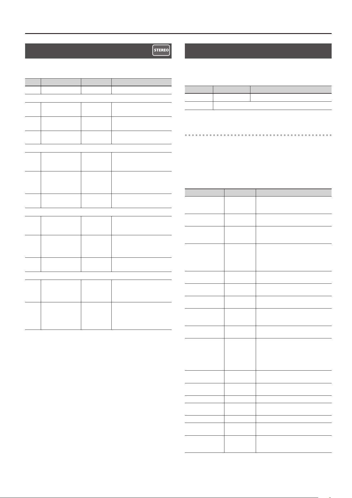
Eect Name TYPE Explanation
Harmonist is an eect where the amount
HARMONIST —
OVERTONE
* FX2 only
SOUND HOLD —
AC. PROCESSOR
PHASER —
FLANGER —
TREMOLO —
ROTARY 1 —
ROTARY 2 —
UNI-V —
PAN —
SLICER —
VIBRATO —
RING MOD —
HUMANIZER — This can create human vowel-like sounds.
2X2 CHORUS —
SUB DELAY —
TERA ECHO
* FX2 only
—
(Acoustic
Processor)
—
of shifting is adjusted according to an
analysis of the guitar input, allowing you
to create harmony based on diatonic
scales.
This eect uses MDP technology to add
new harmonics to the sound, producing
resonance and richness that was not
present in the original sound.
You can have sound played on the guitar
be held continuously. This eect allows
you to perform the melody in the upper
registers while holding a note in the lower
registers.
This processor allows you to change the
sound produced by the pickup on an
acoustic electric guitar, creating a richer
sound similar to that obtained with a
microphone placed close to the guitar.
By adding varied-phase portions to the
direct sound, the phaser eect gives a
whooshing, swirling character to the
sound.
The anging eect gives a twisting,
jet-airplane-like character to the sound.
Tremolo is an eect that creates a cyclic
change in volume.
This produces an eect like the sound of a
rotary speaker.
This provides rotation that has a dierent
feel than Rotary 1.
This models a Uni-Vibe.
Although this resembles a phaser eect,
it also provides a unique undulation that
you can’t get with a regular phaser.
With the volume level of the left and right
sides alternately changing, when playing
sound in stereo, you can get an eect that
makes the guitar sound appear to y back
and forth between the speakers.
This consecutively interrupts the sound
to create the impression that a rhythm
backing phrase is being played.
This eect creates vibrato by slightly
modulating the pitch.
This creates a bell-like sound by
ring-modulating the guitar sound with
the signal from the internal oscillator.
The sound can be unmusical and lack
distinctive pitches.
This allows you to achieve a more natural
chorus sound.
This is a delay with the maximum delay
time of 1,000 ms. This eect is useful for
making the sound fatter.
This eect uses MDP technology to create
a unique ambience and a spaciousness
that changes according to your picking
dynamics.
T. WAH
You can produce a wah eect with the lter changing in response
to the guitar level.
Knob Parameter Value Explanation
Page 1
Selects the wah mode.
[1] MODE
[2] POLAR
[3] SENS 0–100
[4] FREQ 0–100
Page 2
[1] PEAK 0–100
E.LEVEL
[3]
(EFFECT
LEVEL)
DIR.MIX
[4]
(DIRECT MIX)
LPF
BPF
Selects the direction in which the lter will change in
response to the input.
DOWN The frequency of the lter will fall.
UP The frequency of the lter will rise.
0–100 Adjusts the volume of the eect sound.
0–100 Adjusts the volume of the direct sound.
Low pass lter. This provides a wah eect
over a wide frequency range.
Band pass lter. This provides a wah eect in
a narrow frequency range.
Species the sensitivity with which the lter
changes in the direction specied by the
POLAR setting.
Higher values will produce a stronger tone
which emphasizes the wah eect more. With
a setting of 0, the strength of picking will
have no eect.
Adjusts the center frequency of the Wah
eect.
Adjusts the way in which the wah eect
applies to the area around the center
frequency.
Higher values will produce a stronger tone
which emphasizes the wah eect more. With
a value of 50 a standard wah sound will be
produced.
AUTO WAH
This changes the ltering over a periodic cycle, providing an
automatic wah eect.
Knob Parameter Value Explanation
Page 1
Selects the wah mode.
[1] MODE
[2] RATE
[3] DEPTH 0–100 Adjusts the depth of the eect.
[4] FREQ 0–100
Page 2
LPF
BPF
0–100,
BPM
–
Low pass lter. This provides a wah eect
over a wide frequency range.
Band pass lter. This provides a wah eect in
a narrow frequency range.
Adjusts the frequency (speed) of the change.
* When set to BPM, the value of each
parameter will be set according to the
value of the “MASTER BPM” specied for
each patch. This makes it easier to achieve
eect sound settings that match the
tempo of the song.
* If, due to the tempo, the time is longer
than the range of allowable settings, it is
then synchronized to a period either 1/2 or
1/4 of that time.
Adjusts the center frequency of the Wah
eect.
8
Page 9
EFFECT
Knob Parameter Value Explanation
Adjusts the way in which the wah eect
applies to the area around the center
[1] PEAK 0–100
E.LEVEL
[3]
[4]
(EFFECT
LEVEL)
DIR.MIX
(DIRECT MIX)
0–100 Adjusts the volume of the eect sound.
0–100 Adjusts the volume of the direct sound.
frequency.
Higher values will produce a stronger tone
which emphasizes the wah eect more. With
a value of 50 a standard wah sound will be
produced.
SUB WAH
You can control the wah eect in real time by adjusting the
expression pedal connected to the CTL/EXP jack.
Knob Parameter Value Explanation
Page 1
Selects the wah mode.
This models the sound of the
CRY BABY wah pedal popular
in the ’70s.
This models the sound of the
VOX V846.
This is a wah sound featuring
a bold tone.
This wah has a rened
sound with no unusual
characteristics.
This expanded wah features
a variable range compatible with seven-string and
baritone guitars.
This completely original eect
oers enhancements on the
characteristic resonances
produced by analog synth
lters.
Adjusts the position of the
wah pedal.
* This parameter is used after
it’s been assigned to an EXP
Pedal or similar controller.
Selects the tone produced
when the heel of the EXP
Pedal is depressed.
Selects the tone produced
when the toe of the EXP Pedal
is depressed.
Adjusts the volume of the
eect sound.
Adjusts the volume of the
direct sound.
[1] TYPE
PD.POS
[2]
(PEDAL POSITION)
PD.MIN
[3]
(PEDAL MIN)
PD.MAX
[4]
(PEDAL MAX)
Page 2
E.LEVEL
[1]
(EFFECT LEVEL)
DIR.MIX
[2]
(DIRECT MIX)
CRY
(CRY WAH)
VO
(VO WAH)
FAT (FAT WAH)
LIGHT
(LIGHT WAH)
7STRING
(7STRING WAH)
RESO
(RESO WAH)
0–100
0–100
0–100
0–100
0–100
ADV. COMP
This is an eect that produces a long sustain by evening out the
volume level of the input signal. You can also use it as a limiter to
suppress only the sound peaks and prevent distortion.
Knob Parameter Value Explanation
Page 1
Selects the compressor type.
BOSS
(BOSS COMP)
HI-BAND
LIGHT
D-COMP This models a MXR DynaComp.
[1] TYPE
[2] SUSTAIN 0–100
[3] ATTACK 0–100 Adjusts the attack time.
[4] LEVEL 0–100 Adjusts the volume.
Page 2
[1] TONE -50–+50 This adjusts the tone.
ORANGE
FAT
MILD
STEREO
(STEREO COMP)
This models a BOSS CS-3.
This is a compressor that adds an
even stronger eect in the high
end.
This is a compressor with a light
eect.
This is modeled on the sound
of the Dan Armstrong ORANGE
SQUEEZER.
When applied heavily, this compressor eect provides a fat tone with a
boosted midrange.
When applied heavily, this
compressor eect produces a sweet
tone with the high end cut.
This selects a stereo compressor.
Adjusts the range (time) over which
low-level signals are boosted. Larger
values will result in longer sustain.
LIMITER
The limiter attenuates loud input levels to prevent distortion.
Knob Parameter Value Explanation
Page 1
Selects the limiter type.
BOSS
(BOSS LIMITER)
[1] TYPE
THRESH
[2]
(THRESHOLD)
[3] RATIO 1:1–INF:1
[4] LEVEL 0–100 Adjusts the volume.
Page 2
[1] ATTACK 0–100
[2] RELEASE 0–100 Adjusts the release time.
160D
(RACK 160D)
RACK U
(VINAGE RACK U)
0–100
This selects a stereo limiter.
This models a dbx 160X.
This models a UREI 1178.
Adjust this as appropriate for
the input signal from your
guitar. When the input signal
level exceeds this threshold
level, limiting will be applied.
This selects the compression
ratio used with signals in
excess of the threshold level.
Adjusts the strength of the
picking attack when the
strings are played. Higher
values result in s sharper
attack, creating a more clearly
dened sound.
9
Page 10
EFFECT
SUB OD/DS
This eect distorts the sound to create long sustain.
Knob Parameter Value Explanation
Page 1
Refer to “OD/DS TYPE” (p. 3).
[1] TYPE
[2] DRIVE 0–120 Adjusts the depth of distortion.
[3] TONE -50–+50 Adjusts the tone.
E.LEVEL
[4]
(EFFECT LEVEL)
Page 2
[1] BOTTOM -50–+50
DIR.MIX
[2]
(DIRECT MIX)
SOL.SW
[3]
(SOLO SW)
SOL.LV
[4]
(SOLO LEVEL)
* “CUSTOM” is not available.
* “A-DIST” can be used only with FX2.
0–100
0–100
OFF, ON The tone to one suitable for solos.
0–100
Adjusts the volume of the eect
sound.
Adjusts the tone for the low
frequency range. Turning this to the
left (counterclockwise) produces a
sound with the low end cut; turning
it to the right boosts the low end in
the sound.
Adjusts the volume of the direct
sound.
Adjusts the volume level when the
Solo Sw is ON.
GRAPHIC EQ
This adjusts the tone. You can adjust the sound quality in ten bands.
Knob Parameter Value Explanation
LM.FREQ
[1]
(LOW-MID FREQUENCY)
[2] LM.Q (LOW-MID Q) 0.5–16
LM.GAIN
[3]
(LOW-MID GAIN)
Page 3
HM.FREQ
[1]
(HIGH-MID FREQUENCY)
HM.Q
[2]
(HIGH-MID Q)
HM.GAIN
[3]
(HIGH-MID GAIN)
Page 4
LO.CUT
[1]
(LOW CUT)
HI.CUT
[4]
(HIGH CUT)
20 Hz–10.0 kHz
-20–+20 dB
20 Hz–10.0 kHz
0.5–16
-20–+20 dB
FLAT, 20 Hz–800 Hz
630 Hz–
12.5 kHz, FLAT
Species the center of
the frequency range that
will be adjusted by the
LOW-MID GAIN.
Adjusts the width of the
area aected by the EQ
centered at the LOW-MID
FREQ. Higher values will
narrow the area.
Adjusts the low-middle
frequency range tone.
Species the center of
the frequency range that
will be adjusted by the
HIGH-MID GAIN.
Adjusts the width of the
area aected by the EQ
centered at the HIGH-MID
FREQ. Higher values will
narrow the area.
Adjusts the high-middle
frequency range tone.
This sets the frequency
at which the low cut lter
begins to take eect. When
“Flat” is selected, the low
cut lter will have no
eect.
This sets the frequency at
which the high cut lter
begins to take eect. When
“FLAT” is selected, the
high cut lter will have no
eect.
Knob Parameter Value
Page 1
[1] 31 Hz
[2] 62 Hz
[3] 125 Hz
[4] 250 Hz
Page 2
[1] 500 Hz
[2] 1 kHz
[3] 2 kHz
[4] 4 kHz
Page 3
[1] 8 kHz
[2] 16 kHz
[4] LEVEL -20–+20 dB
-20–+20 dB
PARAMETRIC EQ
This adjusts the tone. You can adjust the sound quality in four
bands.
Knob Parameter Value Explanation
Page 1
LO.GAIN
[1]
(LOW GAIN)
HI.GAIN
[2]
(HIGH GAIN)
[4] LEVEL -20–+20 dB
Page 2
-20–+20 dB
-20–+20 dB
Adjusts the low frequency
range tone.
Adjusts the high frequency
range tone.
Adjusts the overall volume
level of the equalizer.
TONE MODIFY
This changes the tone of the connected guitar.
Knob Parameter Value Explanation
Page 1
Selects the type of tone modication.
FAT
PRES (PRESENCE)
MILD
[1] TYPE
[2] LOW -50–+50
[3] HIGH -50–+50
[4] LEVEL 0–100
Page 2
[1] RESO 0–100
TIGHT
ENHANC (ENHANCE)
RESO1 – 3
(RESONATOR1–3)
Fat tone with boosted mid
range.
Bright tone with boosted
high-mid range.
Mild tone with the high end
cut back.
Tone with the low frequencies
cut.
Tone with the high frequencies
boosted.
This produces a tone with
greater power and punch
by adding resonance in the
low-frequency range and
midrange.
Adjusts the tone for the low
frequency range.
Adjusts the tone for the high
frequency range.
Adjusts the volume of the
eect sound.
This adjusts the strength of
the low-end and midrange
resonance when TYPE is set to
RESO 1, 2, or 3.
10
Page 11
EFFECT
GUITAR SIM
Simulation of the characteristics of particular guitar components
such as pickups and dierent guitar bodies allows you to switch
among a number of dierent guitar types all while using a single
guitar.
Knob Parameter Value Explanation
Page 1
Selects the type of the guitar simulator.
S"H
H"S
H"HF
(HALF TONE)
S"HLW
(HOLLOW)
[1] TYPE
H"HLW
S"AC
(ACOUSTIC)
H"AC
(ACOUSTIC)
P"AC
(PIEZO
"ACOUSTIC)
[2] LOW -50–+50 Adjusts the low frequency range tone.
[3] HIGH -50–+50
[4] LEVEL 0–100
Page 2
[1] BODY 0–100
Changes from a single-coil pickup
tone to a humbucking pickup tone.
Changes from a humbucking pickup
tone to a single-coil pickup tone.
Changes from a humbucking pickup
tone to a single-coil pickup half tone.
Changes a single-coil pickup tone to
a hollow body tone with the body
resonance added.
Changes a humbucking pickup tone
to a hollow body tone with the body
resonance added.
Changes a single-coil pickup tone to
an acoustic guitar tone.
Changes a humbucking pickup tone
to an acoustic guitar tone.
Changes a piezo pickup tone to an
acoustic guitar tone.
Adjusts the high frequency range
tone.
Adjusts the volume of the eect
sound.
Adjusts the way the body sounds
when TYPE is set to SHLW, HHLW, SAC,
HAC or PAC.
The body sound increases as the value
is raised; reducing the value produces
a tone similar to that from a piezo
pickup.
SLOW GEAR
This produces a volume-swell eect (“violin-like” sound).
Knob Parameter Value Explanation
Adjusts the sensitivity of the slow gear. When
it is set to a lower value, the eect of the slow
[1] SENS 0–100
RISE.TM
[2]
(RISE TIME)
[4] LEVEL 0–100 Adjusts the volume of the eect sound.
0–100
gear can be obtained only with a stronger
picking, while no eect is obtained with a
weaker picking. When the value is set higher,
the eect is obtained even with a weak
picking.
Adjusts the time needed for the volume to
reach its maximum from the moment you
begin picking.
DEFRETTER
This simulates a fretless guitar.
Knob Parameter Value Explanation
Page 1
[1] SENS 0–100
[2] DEPTH 0–100
[3] TONE -50–+50
E.LEVEL
[4]
(EFFECT LEVEL)
Page 2
[1] ATTACK 0–100
[2] RESO 0–100
DIR.MIX
[4]
(DIRECT MIX)
0–100
0–100
This controls the input sensitivity of
the defretter.
This controls the rate of the
harmonics.
Adjusts the amount of blurring
between the notes.
Adjusts the volume of the eect
sound.
Adjusts the attack of the picking
sound.
Adds a characteristically resonant
quality to the sound.
Adjusts the volume of the direct
sound.
AC. GUITAR SIM
This eect simulates the tonal character of an acoustic guitar.
Knob Parameter Value Explanation
[1] BODY 0–100 Adjusts the body resonance.
[2] LOW -50–+50
[3] HIGH -50–+50
[4] LEVEL 0–100 Species the volume of the eect.
Species the sense of volume for the
low-frequency range.
Species the sense of volume for the
high-frequency range.
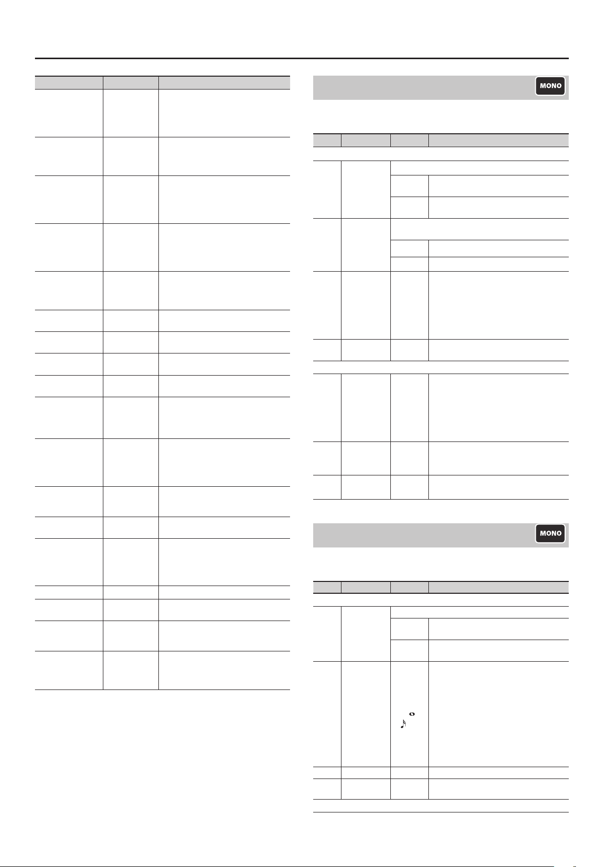
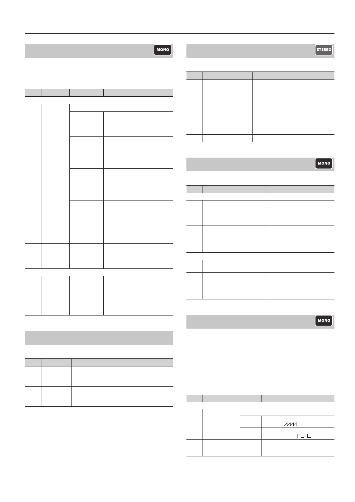
WAVE SYNTH
This is a synth sound that processes the guitar input signal.
* When you use a wave synthesizer, observe the following points.
• Because of the need to analyze the pitch, chords (two or more sounds
played simultaneously) cannot be played. Be sure to mute all the
other strings and play only one note at a time.
• If the unit cannot detect the attack, it may not sound correctly. If the
unit cannot detect the attack, it may not sound correctly.
• The sensitivity may vary according to the guitar’s TONE knob and
pickup type.
Knob Parameter Value Explanation
Page 1
Selects a wave type which the synth sound is based.
[1] WAVE
[2] CUTOFF 0–100
SAW
SQUARE
Creates a synth sound with a saw
waveform (
Creates a synth sound with the
square waveform (
Adjusts the frequency where the
harmonics contents of the sound are
cut o.
).
).
11
Page 12
EFFECT
Knob Parameter Value Explanation
This adjusts the amount of resonance
[3] RESO 0–100
SENS
[4]
Page 2
[1]
[2]
[3]
[4]
(FILTER SENS)
DECAY
(FILTER DECAY)
DEPTH
(FILTER DEPTH)
SYN.LVL
(SYNTH LEVEL)
DIR.MIX
(DIRECT MIX)
0–100
0–100
0–100
0–100 Adjusts the volume of the synth sound.
0–100 Adjusts the volume of the direct sound.
(and the tone coloration) in the synth
sound. The higher the value, the
more the synth tone coloration is
emphasized.
This adjusts the amount of ltering
applied in response to the input.
This sets the time needed for the lter
to nish its sweep.
Adjusts the depth of the lter. When
the value is higher, the lter will change
more drastically.
SITAR SIM.
This simulates the sound of the sitar.
Knob Parameter Value Explanation
Page 1
Adjusts the sensitivity of the sitar.
When it is set to a lower value, no
eect of the sitar is obtained with
[1] SENS 0–100
[2] DEPTH 0–100
[3] TONE -50–+50
E.LEVEL
[4]
(EFFECT LEVEL)
Page 2
[1] RESO 0–100
[2] BUZZ 0–100
DIR.MIX
[4]
(DIRECT MIX)
0–100 Adjust the volume of the sitar sound.
0–100
weaker picking, while stronger
picking produces the eect. When it
is set to a higher value, the eect of
the sitar can be obtained whether the
picking is weak or strong.
This adjusts the amount of eect
applied.
This adjusts the tone. The high end is
boosted as the value increases.
This adjusts the undulation of the
resonance.
Adjusts the amount of characteristic
buzz produced by the “buzz bridge”
when the strings make contact with it.
Adjusts the volume of the direct
sound.
OCTAVE
This adds a note one octave lower, creating a richer sound.
Knob Parameter Value Explanation
This selects the register to which the eect is
applied.
B1 (corresponds to the sound
RANGE 1 (B1–E6)
RANGE 2 (B1–E5)
[1] RANGE
RANGE 3 (B1–E4)
RANGE 4 (B1–E3)
12
of an open 7th string) to E6
(corresponds to the 1st string
played at the 24th fret)
B1 (corresponds to the sound
of an open 7th string) to E5
(corresponds to the 1st string
played at the 12th fret)
B1 (corresponds to the sound
of an open 7th string) to E4
(corresponds to the sound of
an open 1st string)
B1 (corresponds to the sound
of an open 7th string) to E3
(corresponds to the 4th string
played at the 2nd fret)
Knob Parameter Value Explanation
[3]
[4]
E.LEVEL
(EFFECT LEVEL)
DIR.MIX
(DIRECT MIX)
0–100
0–100
Adjusts the volume of the
sound one octave below.
Adjusts the volume of the
direct sound.
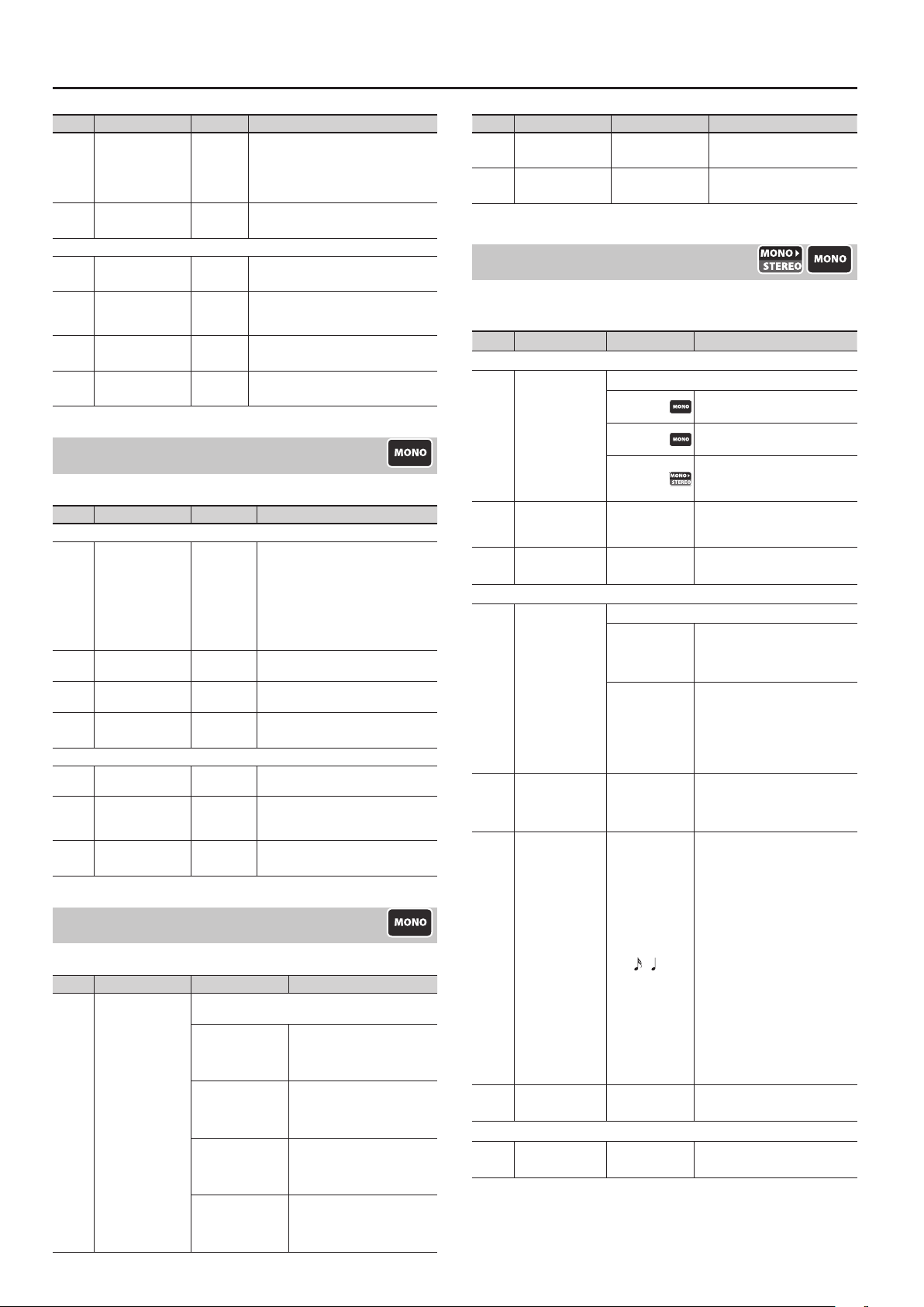
PITCH SHIFTER
This eect changes the pitch of the original sound (up or down)
within a range of two octaves.
Knob Parameter Value Explanation
Page 1
Selects the number of voices for the pitch shift sound.
1VOICE
[1] VOICE
[2]
1:PITCH
[3]
2:PITCH
DIR.MIX
[4]
(DIRECT MIX)
Page 2/Page 3 (if VOICE is set to “1VOICE”: page 2 only)
1:MODE
[1]
2:MODE
1:FINE
[2]
2:FINE
1:P-DLY
(1:PRE DELAY)
[3]
2:P-DLY
(2:PRE DELAY)
1:LEVEL
[4]
2:LEVEL
Page 4 (if VOICE is set to “1VOICE”: page 3)
1:F-BAK
[1]
(1:FEEDBACK)
2MONO
2STEREO
-24–+24
0–100
Selection for the pitch shifter mode.
FAST,
MEDIUM,
SLOW
MONO
-50–+50
0 ms–300 ms,
–
BPM
0–100
0–100
One-voice pitch-shifted sound
output in monaural.
Two-voice pitch-shifted sound
(PS1, PS2) output in monaural.
Two-voice pitch-shifted sound
(PS1, PS2) output through left and
right channels.
Adjusts the amount of pitch
shift (the amount of interval) in
semitone steps.
Adjusts the volume of the direct
sound.
The response is slower in the
order of FAST, MEDIUM and SLOW,
but the modulation is lessened in
the same order.
MONO is used for inputting single
notes.
* You may be unable to produce
the intended eect when
playing chords (two or more
notes played simultaneously).
Make ne adjustments to
the interval. The amount of
the change in the Fine 100 is
equivalent to that of the Pitch 1.
Adjusts the time from when the
direct sound is heard until the
pitch shifted sounds are heard.
Normally you can leave this set
at 0 ms.
* When set to BPM, the value
of each parameter will be set
according to the value of the
“MASTER BPM” specied for
each patch. This makes it easier
to achieve eect sound settings
that match the tempo of the
song.
* If, due to the tempo, the time
is longer than the range of
allowable settings, it is then
synchronized to a period either
1/2 or 1/4 of that time.
Adjusts the volume of the pitch
shifter.
Adjusts the feedback amount of
the pitch shift sound.
Page 13
EFFECT
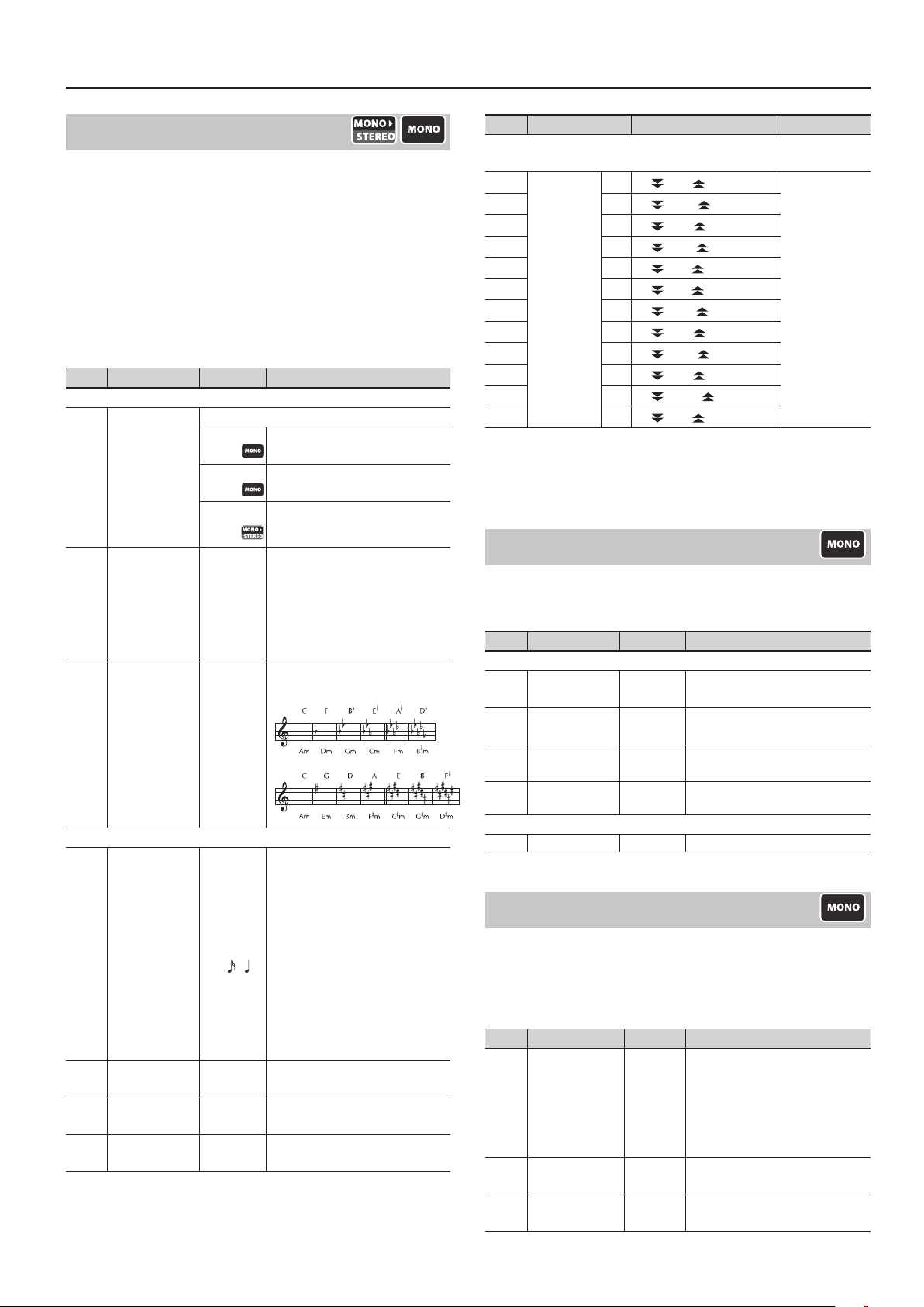
HARMONIST
Harmonist is an eect where the amount of shifting is adjusted
according to an analysis of the guitar input, allowing you to create
harmony based on diatonic scales.
* Because of the need to analyze the pitch, chords (two or more
sounds played simultaneously) cannot be played. Be sure to
mute all the other strings and play only one note at a time.
* If the unit cannot detect the attack, it may not sound correctly. If
the unit cannot detect the attack, it may not sound correctly.
* The sensitivity may vary according to the guitar’s TONE knob
and pickup type.
* For the USB SECONDARY audio routing (p. 34), the harmonist
eect cannot be used on audio from USB IN.
Knob Parameter Value Explanation
Page 1
Selects the number of voices for the pitch shift sound.
1VOICE
[1] VOICE
[2]
1:HARM
[3]
2:HARM
KEY
[4]
(MASTER KEY)
Page 2/Page 3 (if VOICE is set to “1VOICE”: page 2 only)
1:P-DLY
(1:PRE DELAY)
[1]
2:P-DLY
(2:PRE DELAY)
1:F-BAK
[2]
(1:FEEDBACK)
1:LEVEL
[3]
2:LEVEL
DIR.MIX
[4]
(DIRECT MIX)
2MONO
2STEREO
-2 oct–+2
oct, USER
C (Am)–B
(G#m)
0 ms–300
ms,
BPM
0–100
0–100
0–100
One pitch-shifted voice is output in
monaural.
Two pitch-shifted voices are output in
monaural.
Two pitch-shifted voices are output
to the L-channel and the R-channel
respectively.
This determines the pitch of the sound
added to the input sound, when you
are making a harmony.
It allows you to set it by up to 2 octaves
higher or lower than the input sound.
When the scale is set to USER, this
parameter sets the user scale number
to be used.
The key setting corresponds to the key
of the song (#, b) as follows.
Major
Minor
Major
Minor
Adjusts the time from when the direct
sound is heard until the harmonist
sounds are heard. Normally you can
leave this set at 0 ms.
* When set to BPM, the value of each
parameter will be set according
to the value of the “MASTER BPM”
specied for each patch. This makes
–
it easier to achieve eect sound
settings that match the tempo of
the song.
* If, due to the tempo, the time is
longer than the range of allowable
settings, it is then synchronized to a
period either 1/2 or 1/4 of that time.
Adjusts the feedback amount of the
harmonist sound.
Adjusts the volume of the harmony
sound.
Adjusts the volume of the direct
sound.
Knob Parameter Value Explanation
For 1VOICE: pages 3–5
For 2MONO or 2STEREO: pages 4–6 (1:HARM), 7–9 (2:HARM)
[1]
[2] Db
[3] D
[4] Eb
[1] E
[2] F
USER SCALE
*1 *2
[3] F#
[4] G
[1] Ab
[2] A
[3] Bb
[4] B
*1 This can be specied if 1:HARM or 2:HARM is “USER.”
*2 The correspondence between the note names and the knobs diers depending
on the specied KEY. Knob [1] of the rst page is the tonic (root note) of the
specied KEY. The table shows the example of when KEY is set to C (Am).
C
-24
-24
-24
-24
-24
-24
-24
-24
-24
-24
-24
-24
C–+24 C
D²–+24 D²
D–+24 D
E²–+24 E²
E–+24 E
F–+24 F
F¾–+24 F¾
G–+24 G
A²–+24 A²
A–+24 A
B²–+24– B²
B–+24 B
You can specify a
pitch in the range
two octaves
above or below
the direct sound.
OVERTONE (FX2 Only)
This eect uses MDP technology to add new harmonics to the
sound, producing resonance and richness that was not present in
the original sound.
Knob Parameter Value Explanation
Page 1
LWR.LVL
[1]
(LOWER LEVEL)
UPR.LVL
[2]
(UPPER LEVEL)
DIR.MIX
[3]
(DIRECT MIX)
[4] DETUNE 0–100
Page 2
[1] TONE -50–+50 This adjusts the tone.
0–100
0–100
0–100 Adjusts the volume of the direct sound.
Adjusts the volume of the harmonic
one octave below.
Adjusts the volume of the harmonic
one octave above.
Adjusts the amount of the detune
eect that adds depth to the sound.
SOUND HOLD
You can have sound played on the guitar be held continuously.
This eect allows you to perform the melody in the upper registers
while holding a note in the lower registers.
* This function will not work properly when two or more notes are
played simultaneously.
Knob Parameter Value Explanation
Switches the hold sound on and o.
Normally, this is controlled with the
CTL pedals.
[1] HOLD OFF, ON
RISE.TM
[2]
[4]
(RISE TIME)
E.LEVEL
(EFFECT LEVEL)
0–100
0–120 Adjusts the volume of the hold sound.
• It is assumed that this parameter will
be assigned to the footswitch.
• Patches are written with the HOLD
parameter set to O.
Adjusts how rapidly the Sound Hold
sound is produced.
13
Page 14
EFFECT
AC. PROCESSOR
This processor allows you to change the sound produced by the
pickup on an acoustic electric guitar, creating a richer sound similar
to that obtained with a microphone placed close to the guitar.
Knob Parameter Value Explanation
Page 1
Selects the modeling type.
SMALL
[1] TYPE
[2] BASS -50–+50
[3] MIDDLE -50–+50 Adjusts the midrange balance.
M.FREQ
[4]
(MIDDLE FREQ)
Page 2
[1] TREBLE -50–+50
PRES
[2]
(PRESENCE)
[4] LEVEL 0–100 Adjusts the volume.
MEDIUM
BRIGHT This is a bright acoustic guitar sound.
POWER This is a powerful acoustic guitar sound.
20.0 Hz–10.0
kHz
-50–+50
This is the sound of a small-bodied
acoustic guitar.
This is a standard, unadorned acoustic
guitar sound.
Adjusts the tone for the low frequency
range.
Species the frequency range to be
adjusted with Middle.
Adjusts the tone for the high frequency
range.
Adjusts the balance in the extended
upper range.
Knob Parameter Value Explanation
Page 2
[1] MANUAL 0–100
[2]
[3]
[4]
STEP.RT
(STEP RATE)
E.LEVEL
(EFFECT LEVEL)
DIR.MIX
(DIRECT MIX)
OFF, 0–100,
BPM
0–100 Adjusts the volume of the phaser.
0–100
Adjusts the center frequency of the
phaser eect.
This sets the cycle of the step function
that changes the rate and depth.
When it is set to a higher value, the
change will be ner. Set this to “O ”
when not using the Step function.
* When set to BPM, the value of each
parameter will be set according
to the value of the “MASTER BPM”
–
specied for each patch. This makes
it easier to achieve eect sound
settings that match the tempo of
the song.
* If, due to the tempo, the time is
longer than the range of allowable
settings, it is then synchronized to a
period either 1/2 or 1/4 of that time.
Adjusts the volume of the direct
sound.
FLANGER
The anging eect gives a twisting, jet-airplane-like character to
the sound.
PHASER
By adding varied-phase portions to the direct sound, the phaser
eect gives a whooshing, swirling character to the sound.
Knob Parameter Value Explanation
Page 1
Selects the number of stages that the phaser eect
will use.
4 STAGE
[1] TYPE
[2] RATE
[3] DEPTH 0–100
RESO
[4]
(RESONANCE)
8 STAGE
12 STAGE
BiPHASE
0–100,
BPM
0–100
This is a four-phase eect. A light
phaser eect is obtained.
This is a eight-phase eect. It is a
popular phaser eect.
This is a twelve-phase eect. A deep
phase eect is obtained.
This is the phaser with two phase shift
circuits connected in series.
This sets the rate of the phaser eect.
* When set to BPM, the value of each
parameter will be set according
to the value of the “MASTER BPM”
specied for each patch. This makes
it easier to achieve eect sound
–
settings that match the tempo of
the song.
* If, due to the tempo, the time is
longer than the range of allowable
settings, it is then synchronized to a
period either 1/2 or 1/4 of that time.
Determines the depth of the phaser
eect.
Determines the amount of resonance
(feedback). Increasing the value will
emphasize the eect, creating a more
unusual sound.
Knob Parameter Value Explanation
Page 1
This sets the rate of the anging
eect.
* When set to BPM, the value of
each parameter will be set according to the value of the “MASTER
[1] RATE
[2] DEPTH 0–100
RESO
[3]
(RESONANCE)
[4] MANUAL 0–100
Page 2
SEPARAT
[1]
(SEPARATION)
LO.CUT
[2]
(LOW CUT)
E.LEVEL
[3]
(EFFECT LEVEL)
DIR.MIX
[4]
(DIRECT MIX)
0–100,
BPM
0–100
0–100
FLAT,
55 Hz–800 Hz
0–100 Adjusts the volume of the anger.
0–100
–
BPM” specied for each patch. This
makes it easier to achieve eect
sound settings that match the
tempo of the song.
* If, due to the tempo, the time
is longer than the range of
allowable settings, it is then
synchronized to a period either
1/2 or 1/4 of that time.
Determines the depth of the
anging eect.
Determines the amount of
resonance (feedback). Increasing
the value will emphasize the eect,
creating a more unusual sound.
Adjusts the center frequency at
which to apply the eect.
Adjusts the diusion. The diusion
increases as the value increases.
This sets the frequency at which the
low cut lter begins to take eect.
When “Flat” is selected, the low cut
lter will have no eect.
Adjusts the volume of the direct
sound.
14
Page 15
EFFECT
TREMOLO
Tremolo is an eect that creates a cyclic change in volume.
Knob Parameter Value Explanation
WAVE
[1]
(WAVE SHAPE)
[2] RATE
[3] DEPTH 0–100 Adjusts the depth of the eect.
[4] LEVEL 0–100 Adjusts the volume.
0–100
0–100,
BPM
Adjusts changes in volume level.
A higher value will steepen wave’s
shape.
Adjusts the frequency (speed) of the
change.
* When set to BPM, the value of each
parameter will be set according
to the value of the “MASTER BPM”
specied for each patch. This
makes it easier to achieve eect
–
sound settings that match the
tempo of the song.
* If, due to the tempo, the time is
longer than the range of allowable
settings, it is then synchronized to
a period either 1/2 or 1/4 of that
time.
ROTARY 1/ROTARY 2
This produces an eect like the sound of a rotary speaker.
ROTARY 1 and ROTARY 2 provide a dierent-feeling sense of
rotation.
UNI-V
This models a Uni-Vibe.
Although this resembles a phaser eect, it also provides a unique
undulation that you can’t get with a regular phaser.
Knob Parameter Value Explanation
Adjusts the rate of the UNI-V eect.
* When set to BPM, the value of each
parameter will be set according to the
value of the “MASTER BPM” specied
[1] RATE
[2] DEPTH 0–100 Adjusts the depth of the UNI-V eect.
[4] LEVEL 0–100 Adjusts the volume.
0–100,
BPM
–
for each patch. This makes it easier
to achieve eect sound settings that
match the tempo of the song.
* If, due to the tempo, the time is longer
than the range of allowable settings, it
is then synchronized to a period either
1/2 or 1/4 of that time.
PAN
With the volume level of the left and right sides alternately
changing, when playing sound in stereo, you can get an eect that
makes the guitar sound appear to y back and forth between the
speakers.
Knob Parameter Value Explanation
Page 1
[1] SPEED SLOW, FAST
RATE.S
[2]
(RATE-SLOW)
RATE.F
[3]
(RATE-FAST )
[4] DEPTH 0–100
Page 2
RISE.TM
[1]
(RISE TIME)
FALL.TM
[2]
(FALL TIME)
B/H.BAL
[3]
(BASS/HORN
BALANCE) *1
[4] LEVEL 0–100 Adjusts the volume.
Page 3
DIR.MIX
[1]
(DIRECT MIX*1
1 ROTARY 2 only.
0–100,
–
BPM
0–100,
BPM
–
0–100
0–100
100:0–0:100
0–100
This parameter changes the
simulated speaker’s rotating
speed (SLOW or FAST).
This parameter adjusts the SPEED
SELECT of rotation when set to
“SLOW.”
This parameter adjusts the SPEED
SELECT of rotation when set to
“FAST.”
* When set to BPM, the value
of each parameter will be set
according to the value of the
“MASTER BPM” specied for
each patch. This makes it easier
to achieve eect sound settings
that match the tempo of the
song.
* If, due to the tempo, the time
is longer than the range of
allowable settings, it is then
synchronized to a period either
1/2 or 1/4 of that time.
This parameter adjusts the
amount of depth in the rotary
eect.
This parameter adjusts the time
it takes for the rotation SPEED
SELECT to change when switched
from “SLOW” to “FAST.”
This parameter adjusts the time
it takes for the rotation SPEED
SELECT to change when switched
from “FAST” to “SLOW.”
Adjusts the volume balance
between the BASS rotor and the
HORN rotor.
Adjusts the volume of the direct
sound.
Knob Parameter Value Explanation
Page 1
This varies the volume level on
AUTO
[1] TYPE
MANUAL
WAVE
[2]
(WAVE SHAPE) *1
[3] RATE *1
[4] DEPTH *1 0–100 Adjusts the depth of the eect.
POS
[2]
(POSITION) *2
Page 2
[4] LEVEL *3 0–100 Adjusts the volume.
*1 Setting available when TYPE is set to AUTO
*2 Setting available when TYPE is set to MANUAL.
*3 If TYPE is set to MANUAL, this is shown in page 1.
0–100
0–100,
–
BPM
L 100–CENTER–
R 100
the left and right according to
the settings for WAVE SHAPE,
RATE, and DEPTH.
Output uses the volume balance
set with POS.
Adjusts changes in volume level.
A higher value will steepen
wave’s shape.
Adjusts the frequency (speed) of
the change.
* When set to BPM, the value
of each parameter will be
set according to the value of
the “MASTER BPM” specied
for each patch. This makes it
easier to achieve eect sound
settings that match the tempo
of the song.
* If, due to the tempo, the time
is longer than the range of
allowable settings, it is then
synchronized to a period either
1/2 or 1/4 of that time.
This adjusts the volume balance
between the left and right
channels.
15
Page 16

EFFECT
SLICER
This consecutively interrupts the sound to create the impression
that a rhythm backing phrase is being played.
Knob Parameter Value Explanation
Page 1
[1] PATTERN P1–P20
[2] RATE
SENS
[3]
(TRIGGER SENS)
E.LEVEL
[4]
(EFFECT LEVEL)
Page 2
DIR.MIX
[1]
(DIRECT MIX)
0–100,
BPM
0–100
0–100
0–100
Select the slice pattern that will be
used to cut the sound.
Adjust the rate at which the sound
will be cut.
* When set to BPM, the value of each
parameter will be set according
to the value of the “MASTER BPM”
specied for each patch. This
makes it easier to achieve eect
–
sound settings that match the
tempo of the song.
* If, due to the tempo, the time is
longer than the range of allowable
settings, it is then synchronized to
a period either 1/2 or 1/4 of that
time.
Adjust the sensitivity of triggering.
With low settings of this parameter,
softly picked notes will not retrigger
the phrase (i.e., the phrase will
continue playing), but strongly
picked notes will retrigger the
phrase so that it will playback from
the beginning. With high settings
of this parameter, the phrase will be
retriggered even by softly picked
notes.
Adjusts the volume of the eect
sound.
Adjusts the volume of the direct
sound.
VIBRATO
This eect creates vibrato by slightly modulating the pitch.
Knob Parameter Value Explanation
Page 1
Adjusts the rate of the vibrato.
* When set to BPM, the value of each
parameter will be set according to the
value of the “MASTER BPM” specied
[1] RATE
[2] DEPTH 0–100 Adjusts the depth of the vibrato.
[3] TRIGGER OFF, ON
RISE.TM
[4]
(RISE TIME)
Page 2
[1] LEVEL 0–100 Adjusts the volume.
0–100,
BPM
0–100
–
16
for each patch. This makes it easier
to achieve eect sound settings that
match the tempo of the song.
* If, due to the tempo, the time is longer
than the range of allowable settings, it is
then synchronized to a period either 1/2
or 1/4 of that time.
This selects on/o of the vibrato.
* It is assumed that this parameter will be
assigned to the footswitch.
This sets the time passing from the
moment the Trigger is turned on until the
set vibrato is obtained.
* When a patch with TRIGGER set to ON is
called up, the eect obtained is identical
to what happens when TRIGGER is
switched from O to On. If you want
the vibrato eect to be produced
immediately after the patches are
switched, set RISE TIME to 0.
RING MOD
The sound can be unmusical and lack distinctive pitches.
Knob Parameter Value Explanation
This selects the mode for the ring modulator.
NORMAL This is a normal ring modulator.
By ring-modulating the
input signal, a bell like sound
is created. The intelligent
ring modulator changes the
oscillation frequency according
[1] MODE
FREQ
[2]
(FREQUENCY)
E.LEVEL
[3]
(EFFECT LEVEL)
DIR.MIX
[4]
(DIRECT MIX)
INTELLI
(INTELLIGENT)
0–100
0–100
0–100
to the pitch of the input sound
and therefore produces a sound
with the sense of pitch, which
is quite dierent from NORMAL.
This eect does not give a
satisfactory result if the pitch of
the guitar sound is not correctly
detected. So, you must use
single notes, not chords.
Adjusts the frequency of the
internal oscillator.
Adjusts the volume of the eect
sound.
Adjusts the volume of the direct
sound.
HUMANIZER
This can create human vowel-like sounds.
Knob Parameter Value Explanation
Page 1
This sets the mode that switches the vowels.
[1] MODE
[2] VOWEL 1 a, e, i, o, u Selects the rst vowel.
[3] VOWEL 2 a, e, i, o, u Selects the second vowel.
[4] SENS *1 0–100
Page 2
[1] RATE
[2] DEPTH 0–100 Adjusts the depth of the eect.
[3] MANUAL *2 0–100
[4] LEVEL 0–100 Adjusts the volume.
*1 Setting available when MODE is set to PICKING.
*2 Setting available when MODE is set to AUTO.
PICKING
AUTO
0–100,
BPM
–
It changes from VOWEL 1 to VOWEL 2
along with the picking. The time spent
for the change is adjusted with the rate.
By adjusting the rate and depth, two
vowels (VOWEL 1 and VOWEL 2) can be
switched automatically.
Adjusts the sensitivity of the
humanizer.
When it is set to a lower value, no
eect of the humanizer is obtained
with weaker picking, while stronger
picking produces the eect. When it is
set to a higher value, the eect of the
humanizer can be obtained whether
the picking is weak or strong.
Adjusts the cycle for changing the two
vowels.
* When set to BPM, the value of each
parameter will be set according
to the value of the “MASTER BPM”
specied for each patch. This makes
it easier to achieve eect sound
settings that match the tempo of
the song.
* If, due to the tempo, the time is
longer than the range of allowable
settings, it is then synchronized to
a period either 1/2 or 1/4 of that time.
Adjusts the cycle for changing the two
vowels. When it is set to lower than 50,
the time for VOWEL 1 is shorter. When
it is set to higher than 50, the time for
VOWEL 1 is longer.
Page 17

EFFECT
2X2 CHORUS
This allows you to achieve a more natural chorus sound.
Knob Parameter Value Explanation
Page 1
Adjust the speed of the chorus
eect for the low frequency range.
* When set to BPM, the value
of each parameter will be set
according to the value of the
“MASTER BPM” specied for
[1]
[2]
[3]
[4]
Page 2
[1]
[2]
[3]
[4]
Page 3
[1]
[4]
LO.RATE
(LOW RATE)
LO.DPT
(LOW DEPTH)
HI.RATE
(HIGH RATE)
HI.DPT
(HIGH DEPTH)
LO.PDLY
(LOW PRE DELAY)
LO.LVL
(LOW LEVEL)
HI.PDLY
(HIGH PRE DELAY)
HI.LVL
(HIGH LEVEL)
XOVER (CROSSOVER
FREQUENCY)
DIR.MIX
(DIRECT MIX)
0–100,
BPM
–
0–100
0–100,
–
BPM
0–100
0.0 ms–40.0
ms
0–100
0.0 ms–40.0
ms
0–100
100 Hz–4.00
kHz
0–100
each patch. This makes it easier
to achieve eect sound settings
that match the tempo of the
song.
* If, due to the tempo, the time
is longer than the range of
allowable settings, it is then
synchronized to a period either
1/2 or 1/4 of that time.
Adjust the depth of the chorus
eect for the low frequency
range. If you wish to use this as a
doubling eect, use a setting of 0.
Adjust the speed of the chorus
eect for the high frequency
range.
* When set to BPM, the value
of each parameter will be set
according to the value of the
“MASTER BPM” specied for
each patch. This makes it easier
to achieve eect sound settings
that match the tempo of the
song.
* If, due to the tempo, the time
is longer than the range of
allowable settings, it is then
synchronized to a period either
1/2 or 1/4 of that time.
Adjust the depth of the chorus
eect for the high frequency
range. If you wish to use this as a
doubling eect, use a setting of 0.
Adjusts the delay of the eect
sound in the low-frequency range.
Extending the pre-delay will
produce the sensation of multiple
sounds (doubling eect).
Adjusts the volume of the eect
sound in the low-frequency range.
Adjusts the delay of the eect
sound in the high-frequency
range. Extending the pre-delay
will produce the sensation of
multiple sounds (doubling eect).
Adjusts the volume of the eect
sound in the high-frequency
range.
This sets the frequency dividing
the low- and high-frequency
ranges.
Adjusts the volume of the direct
sound.
SUB DELAY
This is a delay with the maximum delay time of 1,000 ms. This eect
is useful for making the sound fatter.
Knob Parameter Value Explanation
Page 1
Use this to choose the type of delay.
[1] TYPE
DLY.TIM
[2]
(DELAY TIME)
FEEDBAK
[3]
(FEEDBACK)
E.LEVEL
[4]
(EFFECT LEVEL)
Page 2
HI.CUT
[1]
(HIGH CUT)
[2] TAP TIME *1 0–100%
DIR.MIX
[4]
(DIRECT MIX)
*1 Setting available when TYPE is set to PAN.
MONO
PAN
1 ms–1000 ms,
–
BPM
0–100
0–120
630 Hz–
12.5 kHz, FLAT
0–100
Use this to choose the type of
delay.
Provides a tap delay eect that
divides the delay time between
the left and right channels.
Adjusts the delay time.
* When set to BPM, the value
of each parameter will be
set according to the value of
the “MASTER BPM” specied
for each patch. This makes it
easier to achieve eect sound
settings that match the tempo
of the song.
* If, due to the tempo, the time
is longer than the range of
allowable settings, it is then
synchronized to a period either
1/2 or 1/4 of that time.
Adjusts the volume that is
returned to the input. Higher
settings will result in more delay
repeats.
Adjusts the volume of the delay
sound.
This sets the frequency at which
the high cut lter begins to take
eect. When “FLAT” is selected,
the high cut lter will have no
eect.
Adjusts the delay time of the
left channel delay. This setting
adjusts the L channel delay time
relative to the R channel delay
time (considered as 100%).
Adjusts the volume of the direct
sound.
TERA ECHO (FX2 Only)
This uses MDP technology to create spaciousness and distinctive
ambience that varies according to your picking dynamics.
Knob Parameter Value Explanation
Page 1
Selects the mode of the eect sound.
MONO
[1] MODE
[2] S.TIME 0–100
FEEDBAK
[3]
(FEEDBACK)
STEREO1
STEREO2
0–100
The L and R channels will both
output the same sound.
The eect is applied separately to
the L and R channels.
The L channel outputs the direct
sound, and the R channel outputs
the eect sound.
Adjusts the length of the eect
sound.
Adjusts the decay of the eect
sound.
17
Page 18

EFFECT
Knob Parameter Value Explanation
E.LEVEL
[4]
(EFFECT LEVEL)
Page 2
[1] TONE -50–+50 This adjusts the tone.
DIR.MIX
[2]
(DIRECT MIX)
[4] HOLD OFF, ON
0–100
0–100
Adjusts the volume of the eect
sound.
Adjusts the volume of the direct
sound.
The eect sound is held when you
turn this on.
DELAY
This eect adds delayed sound to the direct sound, giving more
body to the sound or creating special eects.
Knob Parameter Value Explanation
DELAY
ON/OFF
Page 1
OFF, ON Turns this eect on/o.
This selects which type of delay.
* If you switch patches with the Type set to either
DUAL-S, DUAL-P, or DUAL- L/R and then begin to play
immediately after the patches change, you may be
unable to attain the intended eect in the rst portion
of what you perform.
* The stereo eect is cancelled if a monaural eect or
COSM amp is connected after a stereo delay eect.*
SINGLE This is a simple monaural delay.
This delay is specically for stereo
output. This allows you to obtain the tap
delay eect that divides the delay time,
then deliver them to L and R channels.
PAN
STEREO
DUAL-S
EFFECT LEVEL
INPUT
The direct sound is output from the left
channel, and the eect sound is output
from the right channel.
This is a delay comprising two dierent
delays connected in series. Each delay
time can be set in a range from 1 ms to
1000 ms.
DELAY
FEEDBACK
TAP TIME
OUTPUT L
DELAY TIME
OUTPUT R
[1] TYPE
DUAL-P
DUAL-L/R
REVERSE
ANALOG
TAPE
MOD
(MODULATE)
D1 D2
This is a delay comprising two delays
connected in parallel. Each delay time
can be set in a range from 1 ms to 1000
ms.
D1: DELAY 1
D2: DELAY 2
D1
D2
This is a delay with individual settings
available for the left and right channels.
Delay 1 goes to the left channel, Delay 2
to the right.
D1
D2
This produces an eect where the sound
is played back in reverse.
This gives a mild analog delay sound. The
delay time can be set within the range of
1 to 2000 ms.
This setting provides the characteristic
wavering sound of the tape echo. The
delay time can be set within the range of
1 to 3400 ms.
This delay adds a pleasant wavering
eect to the sound.
L
R
18
Page 19

EFFECT
COMMON
Knob Parameter Value Explanation
Page 1 (if TYPE is set to other than DUAL-S, DUAL-P, or DUAL-L/R)
Adjusts the delay time.
* When set to BPM, the value
of each parameter will be
set according to the value of
the “MASTER BPM” specied
DLY.TIM
[2]
(DELAY TIME)
FEEDBAK
[3]
(FEEDBACK)
E.LEVE
[4]
(EFFECT LEVEL)
Page 2 (if TYPE is set to other than DUAL-S, DUAL-P, or DUAL-L/R)
HI.CUT
[1]
(HIGH CUT)
DIR.MIX
[4]
(DIRECT MIX)
1 ms–2000 ms,
BPM
–
0–100
0–120
630 Hz–
12.5 kHz, FLAT
0–100
for each patch. This makes
it easier to achieve eect
sound settings that match
the tempo of the song.
* If, due to the tempo, the time
is longer than the range of
allowable settings, it is then
synchronized to a period
either 1/2 or 1/4 of that time.
Adjusts the volume that is
returned to the input. A higher
value will increase the number
of the delay repeats.
Adjusts the volume of the
delay sound.
This sets the frequency at
which the high cut lter begins
to take eect. When “FLAT” is
selected, the high cut lter will
have no eect.
Adjusts the volume of the
direct sound.
PAN
Knob Parameter Value Explanation
Page 2
Adjusts the delay time of the left channel
[2] TAP TIME 0–100%
delay. This setting adjusts the L channel
delay time relative to the R channel delay
time (considered as 100%).
DUAL-S, DUAL-P, DUAL-L/R
Knob Parameter Value Explanation
Page 2, 3 (if TYPE is set to DUAL-S, DUAL-P, or DUAL-L/R)
Adjusts the delay time.
* When set to BPM, the value
of each parameter will be set
according to the value of the
“MASTER BPM” specied for
each patch. This makes it easier
to achieve eect sound settings
that match the tempo of the
song.
* If, due to the tempo, the time
is longer than the range of
allowable settings, it is then
synchronized to a period either
1/2 or 1/4 of that time.
Adjusts the amount of feedback of
the DELAY 1 (or DELAY 2). A higher
value will increase the number of
the delay repeats.
This sets the frequency at which
the high cut lter begins to take
eect. When “FLAT” is selected, the
high cut lter will have no eect.
Adjusts the volume of the DELAY 1
(or DELAY 2).
[1]
[2]
[3]
[4]
1:TIME
2:TIME
1:F.BAK
(FEEDBACK)
2:F.BAK
(FEEDBACK)
1:HiCUT
(HIGH CUT)
2:HiCUT
(HIGH CUT)
1:LEVEL
2:LEVEL
1 ms–1000 ms,
BPM
–
0–100
630 Hz–
12.5 kHz, FLAT
0–120
MODULATE
Knob Parameter Value Explanation
Page 3
MOD.RT
[1]
(MODULATION RATE)
MOD.DPT (MODULATION
[2]
DEPTH)
0–100
0–100
Adjusts the modulation rate of
the delay sound.
Adjusts the modulation depth
of the delay sound.
CHORUS
In this eect, a slightly detuned sound is added to the original
sound to add depth and breadth.
Knob Parameter Value Explanation
CHORUS
ON/OFF
Page 1
[1] MODE
[2] RATE
[3] DEPTH 0–100
E.LEVEL
[4]
(EFFECT LEVEL)
Page 2
PRE.DLY
[1]
(PRE DELAY)
LO.CUT
[2]
(LOW CUT)
HI.CUT
[3]
(HIGH CUT)
DIR.MIX
[4]
(DIRECT MIX)
OFF, ON Turns this eect on/o.
Selection for the chorus mode.
MONO
STEREO1
STEREO2
0–100,
BPM
0–100
0.0 ms–40.0
ms
FLAT,
20 Hz–800 Hz
630 Hz–
12.5 kHz,
FLAT
0–100
This chorus eect outputs the same
sound from both L channel and R
channel.
This is a stereo chorus eect that
adds dierent chorus sounds to L
channel and R channel.
This stereo chorus uses spatial
synthesis, with the direct sound
output in the L channel and the
eect sound output in the R channel.
Adjust the speed of the chorus eect
for the high frequency range.
* When set to BPM, the value of each
parameter will be set according
to the value of the “MASTER BPM”
specied for each patch. This
makes it easier to achieve eect
–
sound settings that match the
tempo of the song.
* If, due to the tempo, the time is
longer than the range of allowable
settings, it is then synchronized to
a period either 1/2 or 1/4 of that
time.
Adjusts the depth of the chorus
eect.
* To use it for doubling eect, set the
value to 0.
Adjusts the volume of the eect
sound.
Adjusts the time needed for the
eect sound to be output after the
direct sound has been output. By
setting a longer pre delay time, you
can obtain an eect that sounds like
more than one sound is being played
at the same time (doubling eect).
This sets the frequency at which the
low cut lter begins to take eect.
When “Flat” is selected, the low cut
lter will have no eect.
This sets the frequency at which the
high cut lter begins to take eect.
When “FLAT” is selected, the high cut
lter will have no eect.
Adjusts the volume of the direct
sound.
19
Page 20

EFFECT
REVERB
This eect adds reverberation to the sound.
Knob Parameter Value Explanation
REVERB ON/OFF OFF, ON Turns this eect on/o.
Page 1
This selects the reverb type. Various dierent
simulations of space are oered.
Simulates an ambience mic
(o-mic, placed at a distance
AMBIENC
(AMBIENCE)
ROOM
[1] TYPE
TIME
[2]
(REVERB TIME)
PRE.DLY
[3]
(PRE DELAY)
E.LEVEL
[4]
(EFFECT LEVEL)
Page 2
LO.CUT
[1]
(LOW CUT)
HI.CUT
[2]
(HIGH CUT)
[3] DENSITY 0–10
DIR.MIX
[4]
(DIRECT MIX)
Page 3
SPRING
(SPRING SENS)
(TYPE = SPRING
only)
HALL 1
HALL 2
PLATE
SPRING
MOD (MODULATE)
0.1 s–10.0 s
0 ms–500 ms
0–100
FLAT,
20 Hz–800 Hz
630 Hz–
12.5 kHz, FLAT
0–100
0–100
from the sound source) used in
recording and other applications.
Rather than emphasizing the
reverberation, this reverb is used
to produce a sense of openness
and depth.
Simulates the reverberation in
a small room. Provides warm
reverberations.
Simulates the reverberation in a
concert hall. Provides clear and
spacious reverberations.
Simulates the reverberation in
a concert hall. Provides mild
reverberations.
Simulates plate reverberation
(a reverb unit that uses the
vibration of a metallic plate).
Provides a metallic sound with a
distinct upper range.
This simulates the sound of
a guitar amp’s built-in spring
reverb.
This reverb adds the wavering
sound found in hall reverb to
provide an extremely pleasant
reverb sound.
Adjusts the length (time) of
reverberation.
Adjusts the time until the reverb
sound appears.
Adjusts the volume of the reverb
sound.
This sets the frequency at which
the low cut lter begins to take
eect. When “Flat” is selected, the
low cut lter will have no eect.
This sets the frequency at which
the high cut lter begins to take
eect. When “FLAT” is selected,
the high cut lter will have no
eect.
Adjusts the density of the reverb
sound.
Adjusts the volume of the direct
sound.
Adjusts the sensitivity of the
spring eect. When the value is
set higher, the eect is obtained
even with a weak picking.
PEDAL FX
PEDAL FX is an eect that lets you use an expression pedal
connected to the CTL/EXP jack to control WAH or PEDAL BEND. For
details on how to edit the eect that’s assigned to the expression
pedal, refer to ”CTL/EXP” (p. 25).
PEDAL BEND
This lets you use the pedal to get a pitch bend eect.
* Because of the need to analyze the pitch, chords (two or more sounds
played simultaneously) cannot be played.
* To use PEDAL BEND, set EXP PEDAL’s FUNC to PB (PEDAL BEND)
or PB/FV (PEDAL BEND/FOOT VOLUME).
Knob Parameter Value Explanation
[1] PITCH -24–+24
PD.POS
[2]
[3]
[4]
(PEDAL POSITION)
E.LEVEL
(EFFECT LEVEL)
DIR.MIX
(DIRECT MIX)
0–100
0–100
0–100
WAH
The expression pedal connected to the CTL/EXP jack controls the
wah eect in real time.
* To use WAH, set EXP PEDAL’s FUNC to WAH or WAH/FV (WAH/
FOOT VOLUME).
Knob Parameter Value Explanation
Page 1
Selects the type of wah.
CRY (CRY WAH)
VO (VO WAH)
FAT (FAT WAH)
[1] TYPE
PD.POS
[2]
(PEDAL POS)
PD.MIN
[3]
(PEDAL MIN)
PD.MAX
[4]
(PEDAL MAX)
LIGHT
(LIGHT WAH)
7STRING
(7STRING WAH)
RESO
(RESONANCE WAH)
0–100
0–100
0–100
This sets the pitch at the point
where the EXP Pedal is all the way
down.
Adjusts the pedal position for
pedal bend. This parameter is
used after it’s been assigned to an
EXP Pedal or similar controller.
Adjusts the volume of the pitch
bend sound.
Adjusts the volume of the direct
sound.
This models the sound of the
CRY BABY wah pedal popular
in the ’70s.
This models the sound of the
VOX V846.
This is a wah sound featuring
a bold tone.
This wah has a rened
sound with no unusual
characteristics.
This expanded wah features
a variable range compatible with seven-string and
baritone guitars.
This completely original eect
oers enhancements on the
characteristic resonances
produced by analog synth
lters.
Adjusts the position of the
wah pedal.
* This parameter is used after
it’s been assigned to an EXP
Pedal or similar controller.
Selects the tone produced
when the heel of the EXP
Pedal is depressed.
Selects the tone produced
when the toe of the EXP Pedal
is depressed.
20
Page 21

EFFECT
Knob Parameter Value Explanation
Page 2
[1]
[2]
E.LEVEL
(EFFECT LEVEL)
DIR.MIX
(DIRECT MIX)
0–100
0–100
Adjusts the volume of the
eect sound.
Adjusts the volume of the
direct sound.
FOOT VOLUME
FOOT VOLUME
This is a volume control eect.
It’s controlled by the expression pedal connected to the CTL/EXP
jack.
Knob Parameter Value Explanation
MIN
[1]
(VOLUME
MIN)
MAX
[2]
(VOLUME
MAX)
0–100
0–100
Sets the volume when the heel of the EXP
Pedal is depressed.
Selects the volume when the toe of the
EXP Pedal is depressed.
You can select how the actual volume
changes relative to the amount the pedal
is pressed.
Volume
DIVIDER
Within the eect chain, the point where the signal is split into
channels “A” and “B” is called the “divider,” and the point where the
two signals are recombined is called the “mixer.”
You can use the divider to switch between channels “A” and “B,” to
assign strongly picked notes and softly picked notes to dierent
channels, or to assign dierent frequency bands of your guitar
sound to dierent channels.
The mixer lets you adjust the volume balance of channels “A” and “B,”
place them in the stereo eld, or slightly delay the sound of channel
“B” to produce a spacious sound.
DIVIDER MIXER
Knob Parameter Value Explanation
Page 1
[1] MODE
SINGLE
SINGLE Use only one channel, either “A” or “B.”
DUAL Use the two channels “A” and “B.”
CURVE
[3]
(VOLUME
CURVE)
[4] LEVEL 0–100 Adjusts the volume.
SLOW 1,
SLOW 2,
NORMAL,
FAST
Minor
When the pedal is
fully raised
FAST
NORMAL
SLOW 2
SLOW 1
When the
pedal is fully
advanced
If “SINGLE” is selected in [1]
Knob Parameter Value Explanation
Page 1
[2]
CH.SEL
(CHANNEL SELECT)
Ch. A,
Selects the channel to use.
Ch. B
DUAL Ch. A, DUAL Ch. B
If “DUAL” is selected in [1]
Knob Parameter Value Explanation
Page 2, 3
OFF DYNAMIC will not be used.
A:DYN
(Ch.A:DYNAMIC)
[1]
B:DYN
(Ch.B:DYNAMIC)
A:SENS
(Ch.A:DYNAMIC SENS)
[2]
B:SENS
(Ch.B:DYNAMIC SENS)
A:FILTR
(Ch.A:FILTER)
[3]
B:FILTR
(Ch.B:FILTER)
A:CUTOF
(Ch.A:CUTOFF FREQUENCY)
[4]
B:CUTOF
(Ch.B:CUTOFF FREQUENCY)
POLAR+
POLAR-
0–100 Species the picking sensitivity.
OFF The lter will not be used.
LPF
HPF
100 Hz–4
kHz
Only notes picked more
strongly than the DYNAMIC
SENS setting will be output.
Only notes picked more
softly than the DYNAMIC SENS
setting will be output.
Only the region below the
cuto frequency will be
output.
Only the region above the
cuto frequency will be
output.
Cuto frequency
21
Page 22

EFFECT
MIXER
Knob Parameter Value Explanation
STEREO
[1] MODE
PAN L/R
A/B.BAL
[2]
(Ch.A/B
BALANCE)*1
[3] SPREAD *1 0–100
*1 Shown only if DIVIDER MODE is “DUAL.”
100:0–
0:100
Channels “A” and “B” will be mixed and output
in stereo.
Channels “A” and “B” will be assigned
respectively to the L and R OUTPUT jacks.
Adjusts the volume balance of channels “A”
and “B.”
Slightly delays the sound of channel “B” to
make the sound more spacious.
NS1/NS2
This eect reduces the noise and hum picked up by guitar pickups.
Since it suppresses the noise in synchronization with the envelope
of the guitar sound (the way in which the guitar sound decays over
time), it has very little eect on the guitar sound, and does not
harm the natural character of the sound.
Knob Parameter Value Explanation
NS ON/OFF OFF, ON Switches the noise suppressor eect on/o.
Adjust this parameter as appropriate for the
volume of the noise. If the noise level is high,
a higher setting is appropriate. If the noise
THRESH
[1]
(THRESHOLD)
[2] RELEASE 0–100
[4] DETECT
level is low, a lower setting is appropriate.
0–100
* High settings for the threshold parameter
may result in there being no sound when
you play with your guitar volume turned
down.
Adjusts the time from when the noise
suppressor begins to function until the noise
level reaches “0.”
This controls the noise suppressor based on the
volume level for the point specied in Detect.
Input volume from input jack.
INPUT
* Ordinarily, DETECT should be set to
“INPUT.”
Noise suppressor input volume.
* When connected as illustrated below, and
you want to prevent a spatial-type eects
NS
INPUT
FV OUT
sound (such as a delay sound) from being
eradicated by the NS, you should set
DETECT to “NS INPUT.”
(Spatial-type eect)
Volume after passing through Foot Volume.
* If you want to use FV (Foot Volume) in
place of the guitar’s volume control, you
need to set DETECT to “FV OUT.”
INPUT
Foot Volume
ACCEL FX
You can use six types of Accel eects in which operating an external
pedal connected to the CTL/EXP jack produces time-varying
changes in the sound.
* To use the Accel eect, connect a pedal such as the FS-6 to the
CTL/EXP jack, and set MENU"CTL/EXP"CTL1/CTL2 to assign
the FUNC (FUNCTION) as ACCEL.
Knob Parameter Value Explanation
Page 1
S-BEND Applies intense bending.
LASR BM
(LASER BEAM)
RNGMOD
(RING MOD)
[1] TYPE
TWIST
WARP Produces a dream-like sound.
FEEDBKR
(FEEDBACKER)
S-BEND
Applies intense bending.
Knob Parameter Value Explanation
Page 1
-3 oct, -2 oct,
[2] PITCH
RISE.TM
[3]
(RISE TIME)
FALL.TM
[4]
(FALL TIME)
-1 oct, +1 oct,
+2 oct, +3 oct,
+4 oct
0–100
0–100
LASER BEAM
Produces a laser beam-like sound.
NS1DLY
NS1FV
Knob Parameter Value Explanation
Page 2
[1] RATE 0–100 Adjusts the modulation rate of the sound.
[2] DEPTH 0–100 Adjusts the modulation depth of the sound.
RISE.TM
[3]
(RISE TIME)
FALL.TM
[4]
(FALL TIME)
0–100
0–100
Produces a laser beam-like sound.
Produces a metallic sound, creating
the impression that the sound is
being focused.
Produces an aggressive sense of
rotation. Using this in conjunction
with distortion will produce an even
wilder sense of rotation.
Generates feedback performance.
Adjusts the amount of pitch shift in
octave steps.
This parameter adjusts the amount
of time it is to take for the eect to
transition to the maximum.
This parameter adjusts the amount
of time it is to take for the eect to
transition to the original.
This parameter adjusts the amount of time
it is to take for the eect to transition to the
maximum.
This parameter adjusts the amount of time
it is to take for the eect to transition to the
original.
22
Page 23

EFFECT
RING MOD
Produces a metallic sound, creating the impression that the sound
is being focused.
Knob Parameter Value Explanation
Page 1
[2] FREQ 0–100
RISE.TM
[3]
[4]
Page 2
[1]
[2]
[3]
(RISE TIME)
FALL.TM
(FALL TIME)
RNG.LVL
(RING LEVEL)
OCT.LVL
(OCTAVE LEVEL)
DIR.MIX
(DIRECT MIX)
0–100
0–100
0–100 Adjusts the volume of the eect sound.
0–100
0–100 Adjusts the volume of the direct sound.
Adjusts the frequency of the internal
oscillator.
This parameter adjusts the amount
of time it is to take for the eect to
transition to the maximum.
This parameter adjusts the amount
of time it is to take for the eect to
transition to the original.
Adjusts the volume of the one octave
low sound.
TWIST
Produces an aggressive sense of rotation. Using this in conjunction
with distortion will produce an even wilder sense of rotation.
Knob Parameter Value Explanation
Page 1
RISE.TM
[2]
(RISE TIME)
FALL.TM
[3]
(FALL TIME)
[4] LEVEL 0–100 Adjusts the volume of the eect sound.
0–100
0–100
This parameter adjusts the amount of time
it is to take for the eect to transition to the
maximum.
This parameter adjusts the amount of time
it is to take for the eect to transition to the
original.
FEEDBACKER
Generates feedback performance.
* Note that the notes you want to apply feedback to must be
played singly and cleanly.
Knob Parameter Value Explanation
Page 1
Analyzes the pitch of the guitar
sound being input, and then
creates a feedback sound.
An articial feedback sound will
be created internally. When OSC
is selected, the eect is activated
after a single note is played and
the note stabilizes. A feedback
eect is created when the
eect switches on; the feedback
disappears when the OSC eect
switches o.
Adjusts the ease with which
feedback will occur when the
FEEDBACKER is on.
This determines the time needed
for the volume of the feedback
sound to reach its maximum
from the moment the eect is
turned on.
This determines the time needed
for the volume of the one octave
higher feedback sound to reach
its maximum from the moment
the eect is turned on.
Adjusts the volume of the
feedback sound.
Adjusts the volume of the one
octave higher feedback sound.
Adjusts the rate of the vibrato
when the FEEDBACKER is on.
[2] MODE
DEPTH
[3]
*1
RISE.TM
[3]
(RISE TIME)
*2
OCT.RTM
(OCTAVE RISE
[4]
TIME)
*2
Page 2
FEEDBAK
(FEEDBACK
[1]
LEVEL)
*2
OCT.FBK
(OCTAVE
[2]
FEEDBACK LEVEL)
*2
VIB.RAT
[3]
(VIBRATO RATE)*20–100
NORMAL
OSC
(OSCILLATOR)
0–100
0–100
0–100
0–100
0–100
WARP
Produces a dream-like sound.
Knob Parameter Value Explanation
Page 1
RISE.TM
[2]
(RISE TIME)
FALL.TM
[3]
(FALL TIME)
[4] LEVEL 0–100 Adjusts the volume of the eect sound.
0–100
0–100
This parameter adjusts the amount of time
it is to take for the eect to transition to the
maximum.
This parameter adjusts the amount of time
it is to take for the eect to transition to the
original.
VIB.DPT
[4]
(VIBRATO DEPTH)*20–100
*1 MODE=NORMAL only
*2 MODE=OSC only
Adjusts the depth of the vibrato
when the FEEDBACKER is on.
23
Page 24

EFFECT
MASTER SETTING
These settings are applied to the overall patch.
MASTER SETTING
Knob Parameter Value Explanation
Page 1
PAT.LVL
[1]
(PATCH
LEVEL)
USB type B
[3]
(MASTER
BPM)
0–200 Adjusts the volume of the patch.
Adjusts the BPM value for each patch.
* BPM (beats per minute) indicates the
number of quarter note beats that occur
each minute.
40–250
* When you have an external MIDI
device connected, the MASTER BPM
synchronizes to the external MIDI
device’s tempo, making it impossible to
set the MASTER BPM. To enable setting of
the”SYNC” (p. 36), set to INTERNAL.
This sets the key for the FX HARMONIST.
Major
KEY
[4]
(MASTER
KEY)
C (Am) –
B (G#m)
Minor
Major
Minor
MASTER EQ
Knob Parameter Value Explanation
Page 2
LO.GAIN
[1]
(MASTER LOW GAIN)
HI.GAIN
[2]
(MASTER HIGH GAIN)
Page 3
MID.FREQ
[1]
(MASTER MID
FREQUENCY)
MID.Q
[2]
(MASTER MID Q)
MID.GAIN
[3]
(MASTER MID GAIN)
-20–+20 dB
-20–+20 dB
20.0 Hz–10.0
kHz
0.5–16
-20–+20 dB
Adjusts the low frequency
range tone.
Adjusts the high frequency
range tone.
Specify the center of the
frequency range that will
be adjusted by the MASTER
MID GAIN.
Adjusts the width of the
area aected by the EQ
centered at the MASTER
MID FREQ. Higher values will
narrow the area.
Adjusts the middle
frequency range tone.
24
Page 25

MENU
CTL/EXP
Pedal Settings
Connect your footswitch to the CTL/EXP jack as shown in the illustration,
and set its POLARITY switch.
EXP
When Connecting an FS-5U
CTL 1
Cable:
1/4” phone
type#"
1/4” phone type
POLARITY switch
or
When Connecting Two FS-5Us
CTL 1
or
When Connecting an FS-6
CTL 1
CTL 2
POLARITY switch
CTL 2
MODE/POLARITY switch
Cable:
Stereo 1/4” phone type
#"
1/4” phone type x 2
Cable:
Stereo 1/4” phone type
#"
Stereo 1/4” phone type
Using a Pedal to Control Desired Parameters
Here’s how to assign the parameters that will be controlled by the
CTL 1, CTL 2 and the expression pedals.
1. Choose [MENU]"”CTL/EXP”"”CTL1”, ”CTL2”, or ”EXP.”
2. Set the parameter values with knobs [1]–[4].
CTL1, CTL2
Assign the parameters that are controlled by the CTL1 and CTL2
pedals.
Knob
Parameter
[1] FUNC
Value Explanation
OFF No assignment.
ACCEL Switches the ACCEL eect on and o.
CH SEL (DIV CH
SELECT)
OD SL (OD/DS
SOLO)
A/B SL
(A/B SOLO)
A&B SL
(A&B SOLO)
COMP Switches the COMP on and o.
OD/DS Switches the OD/DS on and o.
PREAMP Switches the PREAMP/SPEAKER on and o.
EQ Switches the EQ on and o.
FX1 Switches the FX1 on and o.
FX2 Switches the FX2 on and o.
DELAY Switches the DELAY on and o.
CHORUS Switches the CHORUS on and o.
REVERB Switches the REVERB on and o.
PEDL FX
(PEDAL FX)
TUNER Switches the TUNER on and o.
BPM TAP *1 Used for tap input of the MASTER BPM.
DELY TAP
(DELAY TAP) *1
MIDI ST (MIDI
START)
MMC PLY (MMC
PLAY)
LVL+10 (LEVEL
+10) *1
LVL+20 (LEVEL
+20) *1
LVL-10 (LEVEL
-10) *1
LVL-20 (LEVEL
-20) *1
NUM INC
(NUMBER INC)
*1 *2
NUM DEC
(NUMBER DEC)
*1 *2
FAV INC
(FAVORITE
INC) *2
FAV DEC
(FAVORITE
DEC) *2
Switches between Preamp channel A and B.
Switches the OD/DS SOLO on and o.
Switches the Preamp SOLO on and o.
Switches the preamp SOLO, for both
channel A and B, on and o. If one of the
two channels is o, both will be turned on.
Switches the Pedal FX on and o.
Used for tap input of the delay time.
Controls the Start/Stop of external MIDI
devices (such as sequencers).
Controls the Play/Stop of external MIDI
devices (such as hard disk recorders).
Increases the patch volume level by 10
units.
Increases the patch volume level by 20
units.
Decreases the patch volume level by 10
units.
Decreases the patch volume level by 20
units.
Switches to the next higher patch number.
Switches to the next lowers patch number.
Switches FAVORITE in the order of
A"B"C"D"A...
Switches FAVORITE in the order of
D"C"B"A"D...
*1 The function will activate as soon as you press the pedal, regardless
of whether the SOURCE MODE parameter is MOMENT or TOGGLE.
*2 To switch patches, use MENU"SYSTEM"PREFERENCE to specify
CTL1/2 as SYSTEM, or set CTL1/2’s FUNC to NUMBER INC/DEC for all
of the patches that you want to switch.
25
Page 26

MENU
Knob
[2] MIN
[3] MAX
[4]
Parameter
MODE
(SOURCE
MODE)
Value Explanation
OFF, ON
(or STOP, START,
PLAY)
OFF, ON
(or STOP, START,
PLAY)
This sets the behavior of the value each time the switch is
operation.
MOMENT
TOGGLE
This sets the value for times when the
switch is O.
This sets the value for times when the
switch is On.
The normal state is O (minimum value),
with the switch On (maximum value)
only while the footswitch is depressed.
The setting is toggled On (maximum
value) or O (minimum value) with each
press of the footswitch.
Specifying the External Pedal Function for Each Patch (Assign)
Here’s how the function of an external pedal (footswitch, expression
pedal) connected to the CTL/EXP jack can be specied for each
patch. For each patch, you can make eight dierent assignments
(assign number 1–8) that specify which pedal controls which
parameter.
* Select each individual parameter to specify which pedal will
control each parameter.
1. Choose [MENU]"”CTL/EXP”"”ASSIGN C (COMMON)” or
”ASSIGN 1–8.”
2. Set the parameter values with knobs [1]–[4].
EXP
Here’s how to assign the parameters that will be controlled by an
expression pedal (such as the separately available EV-5) connected
to the CTL/EXP jack.
Knob Parameter Value Explanation
OFF No assignment.
FV
(FOOT VOLUME)
PB
(PEDAL BEND)
[1] FUNC
MIN
[3]
(PATCH LEVEL
MIN) *2
MAX
[4]
(PATCH LEVEL
MAX) *2
This is shown only if PERFORMANCE (p. 35) is set to SYSTEM.
*2 Shown only if PATCH LEVEL is selected in FUNC.
WAH Wah will be assigned.
PB/FV
WAH/FV
PAT LV
(PATCH LEVEL) *1
0–200 Species the minimum value.
0–200 Species the maximum value.
Foot volume will be assigned.
Pedal bend will be assigned.
Pedal bend and foot volume
will be assigned.
Wah and foot volume will be
assigned.
Patch level will be assigned.
ASSIGN COMMON
Knob Parameter Value Explanation
[1]
SENS
(INPUT SENS)
0–100
This adjusts the input sensitivity when INPUT
LEVEL is selected for SOURCE.
ASSIGN 1–8
Knob Parameter Value Explanation
[1] ASSIGN OFF, ON Turns the ASSIGN 1–8 on/o.
Assigns the external footswitch
(FS-5U, FS-6; available separately)
connected to the CTL/EXP jack.
Assigns the external footswitch
(FS-5U, FS-6; available separately)
connected to the CTL/EXP jack.
Assigns the external footswitch
(FS-5U, FS-6; available separately)
connected to the CTL/EXP jack.
Refer to “Virtual expression pedal
system (Internal Pedal / Wave
Pedal)” (p. 31)
Refer to “Virtual expression pedal
system (Internal Pedal / Wave
Pedal)” (p. 31)
The assigned target parameter
will change according to the input
level.
Control Change messages from an
external MIDI device.
Control Change messages from an
external MIDI device.
The normal state is O (minimum
value), with the switch On
(maximum value) only while the
footswitch is depressed.
The setting is toggled On
(maximum value) or O
(minimum value) with each press
of the footswitch.
[2] SOURCE
MODE
[3]
(SOURCE MODE)
Page 2
CATEGORY
[1]
(TARGET
CATEGORY)
[2] TARGET
MIN
[3]
(TARGET MIN)
MAX
[4]
(TARGET MAX)
EXP PDL
(EXP PEDAL)
CTL1 PDL
(CTL1 PEDAL)
CTL2 PDL
(CTL2 PEDAL)
INT PDL
(INTERNAL
PEDAL)
WAV PDL
(WAVE PEDAL)
INPUT
(INPUT LEVEL)
CC#1–#31
CC#64–#95
MOMENT
TOGGLE
This selects the parameter to be changed.
Refer to TARGET list
This sets the minimum value for the range in which
the parameter can change. The value diers depending on the parameter assigned for TARGET parameter.
This sets the maximum value for the range in
which the parameter can change. The value diers
depending on the parameter assigned for TARGET
parameter.
26
Page 27

Knob Parameter Value Explanation
Page 3
ACT.LO
[1]
(ACT RANGE LO)
ACT.HI
[2]
(ACT RANGE HI)
WAV.RT
[3]
(WAVE RATE)
*1
WAV.FM
[4]
(WAVE FORM)
*1
Page 4
TRIGGER
(INT PEDAL
[1]
TRIGGER)
*2
TIME
[2]
(INT PEDAL TIME)*20–100
0–126
1–127
0–100,
–
BPM
When set to BPM, the value of each parameter will
be set according to the value of the “MASTER BPM”
specied for each patch. This makes it easier to
achieve eect sound settings that match the tempo
of the song.
* If, due to the tempo, the time is longer than the
range of allowable settings, it is then synchronized
to a period either 1/2 or 1/4 of that time.
SAW
TRI
SINE
PAT CNG
(PATCH CHANGE)
EXP LO
EXP MID
EXP HI
CTL1 PDL
CTL2 PDL
CC#1–#31
CC#64–#95
You can set the controllable range
for target parameters within the
source’s operational range. Target
parameters are controlled within
the range set with ACT LO and
ACT HI. You should normally set
ACT LO to 0 and ACT HI to 127.
This determines the time spend
for one cycle of the assumed EXP
Pedal.
This is activated when a patch is
selected.
This is activated when an external
expression pedal connected to
the CTL/EXP jack is set to the
minimum position.
This is activated when the
external expression pedal
connected to the CTL/EXP jack
is moved through the middle
position.
This is activated when the
external expression pedal
connected to the CTL/EXP jack is
set to the maximum position.
This is activated when an external
footswitch connected to the CTL/
EXP jack is operated.
This is activated when an external
footswitch connected to the CTL/
EXP jack is operated.
This is activated when a control
change is received.
This is activated when a control
change is received.
This species the time over which
the internal pedal will move from
the toe-raised position to the
toe-down position.
MENU
LINEAR
CURVE
(INT PEDAL
[3]
CURVE)
*2
*1 The WAVE RT and WAVE FM parameters are enabled when the Source parameter
is set to WAVE PDL.
*2 The TRIGGER, TIME, and CURVE parameters are enabled when the SOURCE
parameter is set to INT PEDAL.
SLOW
(SLOW RISE)
FAST
(FAST RISE)
27
Page 28

MENU
TARGET list
CATEGORY TARGET
ON/OFF
TYPE
COMP
OD/DS
PREAMP
SUSTAIN
ATTACK
TONE
LEVEL
ON/OFF
TYPE
DRIVE
BOTTOM
TONE
SOL SW
(SOLO SW)
SOL LV
(SOLO LEVEL)
E.LVL
(EFFECT LEVEL)
DIR MIX
(DIRECT MIX)
C-TYPE (CUSTOM
TYPE)
C-BTM (CUSTOM
BOTTOM)
C-TOP
(CUSTOM TOP)
C-LOW (CUSTOM
LOW)
C-HIGH (CUSTOM
HIGH)
C-CHAR (CUSTOM
CHAR)
ON/OFF
CATEGORY TARGET
TYPE
GAIN
T-COMP
BASS
MIDDLE
TREBLE
PRES (PRESENCE)
LEVEL
BRIGHT
GAIN SW
SOL SW
(SOLO SW)
SOL LV
(SOLO LEVEL)
SP TYPE
MIC TYP
(MIC TYPE)
MIC DIST
(MIC DISTANCE)
MIC POS
(MIC POSITION)
PRAMP
A/B(PREAMP
A/B)
EQ
MIC LVL
(MIC LEVEL)
DIR MIX
(DIRECT MIX)
C-TYPE (CUSTOM
TYPE)
C-BTM (CUSTOM
BOTTOM)
C-EDG (CUSTOM
EDGE)
C-LOW (CUSTOM
LOW)
C-HIGH (CUSTOM
HIGH)
C-CHAR (CUSTOM
CHAR)
SP SIZE (CUSTOM
SPEAKER SIZE)
SP LO
(CUSTOM COLOR
LOW)
SP HI
(CUSTOM COLOR
HIGH)
SP NUM (CUSTOM
SPEAKER NUMBER)
SP CABI (CUSTOM
CABINET)
ON/OFF
LO CUT
(LOW CUT)
LO GAIN
(LOW GAIN)
LM FREQ (LOW-MID
FREQUENCY)
LM Q
(LOW-MID Q)
LM GAIN
(LOW-MID GAIN)
HM FREQ (HIGH-MID
FREQUENCY)
HM Q
(HIGH-MID Q)
HM GAIN
(HIGH-MID GAIN)
HI GAIN
(HIGH GAIN)
HI CUT (HIGH CUT)
LEVEL
CATEGORY TARGET
FX1/FX2
1/2 T.WAH
(FX1/FX2 T.WAH)
1 A.WAH/
2 A.WAH
(FX1 AUTO WAH/
FX2 AUTO WAH)
1/2 S.WAH
(FX1/FX2 SUB WAH)
1/2 A.CMP
(FX1/FX2 ADV
COMP)
1/2 LIMTR
(FX1/FX2 LIMITER)
1/2 OD/DS
(FX1/FX2 OD/DS)
1/2 GEQ
(FX1/FX2 GEQ)
ON/OFF
TYPE
MODE
POLARTY
(POLARITY)
SENS
FREQ
PEAK
E.LVL
(EFFECT LEVEL)
DIR MIX
(DIRECT MIX)
MODE
FREQ
PEAK
RATE
DEPTH
E.LVL
(EFFECT LEVEL)
DIR MIX
(DIRECT MIX)
TYPE
PDL POS
(PEDAL POSITION)
PDL MIN
(PEDAL MIN)
PDL MAX
(PEDAL MAX)
E.LVL
(EFFECT LEVEL)
DIR MIX
(DIRECT MIX)
TYPE
SUSTAIN
ATTACK
TONE
LEVEL
TYPE
ATTACK
THRES
(THRESHOLD)
RATIO
RELEASE
LEVEL
TYPE
DRIVE
BOTTOM
TONE
SOL SW
(SOLO SW)
SOL LV
(SOLO LEVEL)
E.LVL
(EFFECT LEVEL)
DIR MIX
(DIRECT MIX)
31 Hz
62 Hz
125 Hz
250 Hz
500 Hz
1 kHz
2 kHz
4 kHz
8 kHz
16 kHz
LEVEL
CATEGORY TARGET
LO CUT
(LOW CUT)
LO GAIN
(LOW GAIN)
LM FREQ (LOW-MID
FREQUENCY)
LM Q
(LOW-MID Q)
LM GAIN
1/2 PEQ
(FX1/FX2 PEQ)
1/2 TonMD
(FX1/FX2
TONE MODIFY)
1/2 GtrSM
(FX1/FX2 GUITAR
SIM)
1/2 A.SIM
(FX1/FX2 AC.
GUITAR SIM)
1/2 SlGER
(FX1/FX2 SLOW
GEAR)
1/2 DEFRT
(FX1/FX2 DEFRETTER)
1/2 WvSYN
(FX1/FX2 WAVE
SYNTH)
(LOW-MID GAIN)
HM FREQ (HIGH-MID
FREQUENCY)
HM Q
(HIGH-MID Q)
HM GAIN (HIGH-MID
GAIN)
HI CUT
(HIGH CUT)
HI GAIN
(HIGH GAIN)
LEVEL
TYPE
RESO
LOW
HIGH
LEVEL
TYPE
LOW
HIGH
BODY
LEVEL
BODY
LOW
HIGH
LEVEL
SENS
RISE TM
(RISE TIME)
LEVEL
TONE
SENS
ATTACK
DEPTH
RESO
E.LVL
(EFFECT LEVEL)
DIR MIX
(DIRECT MIX)
WAVE
CUTOFF
RESO (RESONANCE)
FLT SNS
(FILTER SENS)
FLT DCY
(FILTER DECAY )
FLT DPT
(FILTER DEPTH)
SYN LVL
(SYNTH LEVEL)
DIR MIX
(DIRECT MIX)
28
Page 29

MENU
CATEGORY TARGET
TONE
SENS
DEPTH
1/2 StrSM
(FX1/FX2 SITAR
SIM)
1/2 OCTAV
(FX1/FX2 OCTAVE)
1/2 PSHFT
(FX1/FX2
PITCH SHIFTER)
1/2 HARM
(FX1/FX2
HARMONIST)
1/2 S.HLD
(FX1/FX2 SOUND
HOLD)
1/2 AcPRO
(FX1/FX2
AC.PROCESSOR)
RESO
BUZZ
E.LVL
(EFFECT LEVEL)
DIR MIX
(DIRECT MIX)
RANGE
OCT LVL (OCTAVE
LEVEL)
DIR MIX
(DIRECT MIX)
VOICE
1 MODE
1 PITCH
1 FINE
(PITCH FINE)
1 PrDLY
(PRE DELAY)
1 LEVEL
2 MODE
2 PITCH
2 FINE
(PITCH FINE)
2 PrDLY
(PRE DELAY)
2 LEVEL
1 F.BAK (FEEDBACK)
DIR MIX
(DIRECT MIX)
VOICE
1 HRMNY
(HARMONY)
1 PrDLY
(PRE DELAY)
1 LEVEL
2 HRMNY
(HARMONY)
2 PrDLY
(PRE DELAY)
2 LEVEL
1 F.BAK (FEEDBACK)
DIR MIX
(DIRECT MIX)
HOLD
RISE TM
(RISE TIME)
E.LVL
(EFFECT LEVEL)
TYPE
BASS
MIDDLE
MID FRQ (MIDDLE
FREQUENCY)
TREBLE
PRES (PRESENCE)
LEVEL
CATEGORY TARGET
TYPE
RATE
DEPTH
MANUAL
1/2 PHASR
(FX1/FX2 PHASER)
1/2 FLNGR
(FX1/FX2 FLANGER)
1/2 TREML
(FX1/FX2 TREMOLO)
1/2 ROTY1
(FX1/FX2 ROTARY 1)
1/2 ROTY2
(FX1/FX2 ROTARY 2)
1/2 UNIV
(FX1/FX2
UNIV)
1/2 PAN
(FX1/FX2
PAN)
RESO (RESONANCE)
STEP RT
(STEP RATE)
E.LVL
(EFFECT LEVEL)
DIR MIX
(DIRECT MIX)
RATE
DEPTH
MANUAL
RESO (RESONANCE)
SEPARAT (SEPARATION)
LOW CUT
E.LVL
(EFFECT LEVEL)
DIR MIX
(DIRECT MIX)
WAVE
(WAVE SHAPE)
RATE
DEPTH
LEVEL
SPEED
(SPEED SELECT)
RAT SLW
(RATE SLOW)
RAT FST
(RATE FAST)
RISE TM
(RISE TIME)
FALL TM
(FALL TIME)
DEPTH
LEVEL
SPEED
(SPEED SELECT)
RAT SLW
(RATE SLOW)
RAT FS
(RATE FAST)
DEPTH
RISE TM
(RISE TIME)
FALL TM
(FALL TIME)
BAL
(BASS/HORN MIX)
LEVEL
DIR MIX
(DIRECT MIX)
RATE
DEPTH
LEVEL
TYPE
WAVE
(WAVE SHAPE)
RATE
DEPTH
POS (POSITION)
LEVEL
CATEGORY TARGET
PAT TERN
RATE
TRG SNS (TRIGGER
1/2 SLICR
(FX1/FX2 SLICER)
1/2 VIBRT
(FX1/FX2 VIBRATO)
1/2 RNGMD
(FX1/FX2 RING
MOD)
1/2 HUMAN
(FX1/FX2 HUMANIZER)
1/2 2X2CH
(FX1/FX2 2X2
CHORUS)
1/2 SubDL
(FX1/FX2 SUB
DELAY)
2 O.TONE
(FX2 OVERTONE)
SENS)
E.LVL
(EFFECT LEVEL)
DIR MIX
(DIRECT MIX)
RATE
DEPTH
TRIGGER
RISE TM
(RISE TIME)
LEVEL
MODE
FREQ (FREQUENCY)
E.LVL
(EFFECT LEVEL)
DIR MIX
(DIRECT MIX)
MODE
VOWEL 1
VOWEL 2
SENS
RATE
DEPTH
MANUAL
LEVEL
XOVER (CROSSOVER
FREQUENCY)
LO RATE
(LOW RATE)
LO DEPT
(LOW DEPTH)
LO PrD (LOW PRE
DELAY)
LO LEVL
(LOW EFFECT LEVEL)
HI RATE
(HIGH RATE)
HI DEPT
(HIGH DEPTH)
HI PrD
(HIGH PRE DELAY)
HI LEVL
(HIGH LEVEL)
DIR MIX
(DIRECT MIX)
TYPE
DLY TIM
(DELAY TIME)
F.BACK (FEEDBACK)
HI CUT
MODEMODE (HIGH
CUT)
E.LVL
(EFFECT LEVEL)
DIR MIX
(DIRECT MIX)
TAP TIM
(TAP TIME)
UPPR LV
(UPPER LEVEL)
LOWR LV (LOWER
LEVEL)
DIR MIX
(DIRECT MIX)
DETUNE
TONE
CATEGORY TARGET
MODE
TIME (S.TIME)
F.BACK (FEEDBACK)
2 T.ECHO
(FX2 TERA ECHO)
DELAY
DELAY
D1
DELAY
D2
DELY MD
(DELAY MOD)
CHORUS
E.LVL
(EFFECT LEVEL)
TONE
DIR MIX
(DIRECT MIX)
HOLD
ON/OFF
TYPE
DLY TIM
(DELAY TIME)
F.BACK (FEEDBACK)
HI CUT
MODEMODE (HIGH
CUT)
E.LVL
(EFFECT LEVEL)
DIR MIX
(DIRECT MIX)
TAPTIME
(PAN TAP TIME)
TIME
F.BACK (FEEDBACK)
HI CUT
MODEMODE (HIGH
CUT)
LEVEL
TIME
F.BACK (FEEDBACK)
HI CUT
MODEMODE (HIGH
CUT)
LEVEL
MOD RAT (MODULATION RATE)
MOD DPT
(MODULATION
DEPTH)
ON/OFF
MODE
RATE
DEPTH
PRE DLY
(PRE DELAY)
LO CUT
(LOW CUT)
HI CUT
MODEMODE (HIGH
CUT)
E.LVL
(EFFECT LEVEL)
DIR MIX
(DIRECT MIX)
29
Page 30

MENU
CATEGORY TARGET
ON/OFF
TYPE
REV TIM
(REVERB TIME)
PRE DLY
(PRE DELAY)
LO CUT
(LOW CUT)
REVERB
PDL FX
(PEDAL FX)
PDL P.B.
(PEDAL PITCH
BEND)
PDL WAH
(PEDAL WAH)
FOT VOL
(FOOT VOLUME)
DIVIDER
MIXER
HI CUT
MODEMODE (HIGH
CUT)
DENSITY
E.LVL
(EFFECT LEVEL)
DIR MIX
(DIRECT MIX)
SPRING
(SPRING SENS)
ON/OFF
PITCH
PDL POS
(PEDAL POSITION)
E.LVL
(EFFECT LEVEL)
DIR MIX
(DIRECT MIX)
TYPE
PDL POS
(PEDAL POSITION)
PDL MIN
(PEDAL MIN)
PDL MAX
(PEDAL MAX)
E.LVL
(EFFECT LEVEL)
DIR MIX
(DIRECT MIX)
VOL CRV (VOLUME
CURVE)
VOL MIN (VOLUME
MIN)
VOL MAX (VOLUME
MAX)
LEVEL
MODE
CH SEL (CHANNEL
SELECT)
ChA DYN
(Ch.A DYNAMIC)
ChA SNS
(Ch.A DYNAMIC
SENS)
ChA FLT
(Ch.A FILTER)
ChA COF
(Ch.A CUTOFF
FREQUENCY)
ChB DYN
(Ch.B DYNAMIC)
ChB SNS
(Ch.B DYNAMIC
SENS)
ChB FLT
(Ch.B FILTER)
ChB COF
(ChB CUTOFF
FREQUENCY)
MODE
Ch BAL
(ChA/B BALANCE)
SPREAD
30
CATEGORY TARGET
ON/OFF
THRES
NS1
NS2
ACCEL
S-BEND
(ACCEL S-BEND)
LASER
(ACCEL LASER
BEAM)
RING
(ACCEL RING MOD)
TWIST
(ACCEL TWIST)
WARP
(ACCEL WARP)
F.BACK
(ACCEL FEEDBACKER)
MASTER
(THRESHOLD)
RELEASE
DETECT
ON/OFF
THRES
(THRESHOLD)
RELEASE
DETECT
ON/OFF
TYPE
PITCH
RISE TM
(RISE TIME)
FALL TM
(FALL TIME)
RATE
DEPTH
RISE TM
(RISE TIME)
FALL TM
(FALL TIME)
FREQ (FREQUENCY)
RISE TM
(RISE TIME)
FALL TM
(FALL TIME)
RNG LVL
(RING LEVEL)
OCT LVL (OCTAVE
LEVEL)
DIR MIX
(DIRECT MIX)
LEVEL
RISE TM
(RISE TIME)
FALL TM
(FALL TIME)
LEVEL
RISE TM
(RISE TIME)
FALL TM
(FALL TIME)
MODE
DEPTH
RISE TM
(RISE TIME)
OCT R.TM (OCTAVE
RISE TIME)
FB LVL (FEEDBACK
LEVEL)
OCT FB (OCTAVE
FEEDBACK LEVEL)
VIB RAT (VIBRATO
RATE)
VIB DPT (VIBRATO
DEPTH)
PAT LVL
(PATCH LEVEL)
LO
(MASTER LOW GAIN)
MID F (MASTER MID
FREQUENCY)
MID Q
(MASTER MID Q)
MID
(MASTER MID GAIN)
HI
(MASTER HI GAIN)
CATEGORY TARGET
MstBPM (MASTER
BMP.KEY
TUNER
TAP
MIDI
PATCH
BPM)
MstKEY
(MASTER KEY)
TUNER
(TUNER SW)
BPM TAP
DLY TAP
(DELAY TAP)
ST/STP
(START/STOP)
PLY/STP
(MMC PLAY/STOP)
LVL +10
(LEVEL +10)
LVL +20
(LEVEL +20)
LVL -10
(LEVEL -10)
LVL -20
(LEVEL -20)
NUM INC (NUMBER
INC)
NUM DEC (NUMBER
DEC)
FAV INC (FAVORITE
INC)
FAV DEC (FAVORITE
DEC)
Page 31

MENU
Virtual expression pedal system (Internal Pedal / Wave Pedal)
By assigning a desired parameter to the virtual expression pedal,
you can produce an eect as though you were operating a physical
expression pedal to change the volume or tone quality in real time.
The virtual expression pedal system provides the following two
types of functions, and you can use the SOURCE setting for ASSIGN
1–8 to choose the desired type.
* If you want to use the internal pedal or wave pedal, set the
ASSIGN parameter MODE to “MOMENT.”
Internal pedal
If SOURCE is set to “INT PDL,” the virtual expression pedal will begin
operating when started by the specied trigger (INT PDL TRIGGER),
modifying the parameter specied by TARGET.
The value changes in a curve
When the trigger occurs
Wave pedal
If SOURCE is set to “WAVE PEDAL,” the virtual expression pedal will
cyclically modify the parameter specied by TARGET in a xed wave
form.
About the Range of a Target’s Change
The value of the parameter selected as the target changes
within the range dened by “Min” and “Max,” as set on the
GT-001.
When using an external footswitch, or other controller that
acts as an on/o switch, “Min” is selected with O (CLOSED),
and “Max” is selected with On (OPEN).
When using an external expression pedal or other controller
that generates a consecutive change in the value, the value
of the setting changes accordingly, within the range set by
the minimum and maximum values. Also, when the target
is of an on/o type, the median value of the received data is
used as the dividing line in determining whether to switch it
on or o.
When using the footswitch:
MAX
MIN
Allowable
Parameter
Settings Range
OFF ON
When using the expression pedal:
MAX
Always changes in a xed curve regardless of the actual pedal
Input level
Input level
The parameter set as the target changes in response to the input
level.
MEMO
If you want to adjust the input sensitivity, set the SENS.
MIN
Allowable
Parameter
Settings Range
When the pedal is
fully raised
When controlling the On/O target with the expression pedal:
Value
ON
OFF
0 127
When the pedal is
fully raised
* The range that can be selected changes according to the target
setting.
* When the “minimum” is set to a higher value than the “maximum,”
the change in the parameter is reversed.
* “The values of settings can change if the target is changed after
the “minimum” and “maximum” settings have been made. If
you’ve changed the target, be sure to recheck the “minimum”
and “maximum” settings.
0 127
When the pedal
is advanced
halfway
When the pedal is
fully advanced
When the pedal
is fully advanced
Degree to
Which Expression Pedal Is
Depressed
31
Page 32

MENU
About the Range of a Controller’s Change
This sets the operational range within which the value of the
setting changes when an expression pedal or other controller
that changes the value consecutively is used as the source.
If the controller is moved outside the operational range, the
value does not change, it stops at “minimum” or “maximum.”
(Example) With ACT LO: 40, ACT HI: 80
MAX
MIN
Allowable
Parameter
Settings Range
0 127
40 80
When the
pedal is fully
raised
Value
ACT
RANGE
LO
ACT
RANGE
HI
Degree to
Which Expression Pedal Is
Depressed
When the
pedal is fully
advanced
ON
Degree to
OFF
0 127
When the
pedal is fully
raised
40 8060
ACT
RANGE
LO
Center
Value
ACT
RANGE
HI
Which Expression Pedal Is
Depressed
When the
pedal is fully
advanced
* When using a footswitch or other on/o switching controller
as the source, leave these at “ACT LO: 0” and “ACT HI: 127.” With
certain settings, the value may not change.
32
Page 33

MENU
SYSTEM
Settings that are shared by the entire GT-001 are called “system
settings.”
MEMO
For details on how to make settings, refer to “Editing: Editing the
Eects” (p. 7) in the owner’s manual.
OUTPUT SELECT
Specify the device (amp) that’s connected to the OUTPUT jacks.
Parameter Value Explanation
JC-120
SMALL AMP
COMBO AMP
STACK AMP
SELECT
JC-120 RETURN
COMBO RETURN
STACK RETURN
LINE/PHONES
INPUT
Here you can make settings related to input.
On the GT-001 you can use either the guitar input or the mic input. You can’t use both
simultaneously.
Choose this setting if the GT-001 is connected
to the guitar input of a Roland JC-120 guitar
amp.
Choose this setting if the GT-001 is connected
to a small guitar amp.
Choose this setting if the GT-001 is connected
to the guitar input of a combo-type guitar
amp (i.e., a single unit that contains the amp
and speaker) other than the JC-120.
For some types of guitar amps, the “JC-120”
setting might produce better results.
Choose this setting if the GT-001 is connected
to the guitar input of a stack-type guitar amp
(i.e., one in which the amp and speaker are
separate units).
Choose this setting if the GT-001 is connected
to the RETURN jack of the JC-120.
Choose this setting if the GT-001 is connected
to the RETURN jack of a combo-type guitar
amp.
Choose this setting if the GT-001 is connected
to the RETURN jack of a combo-type guitar
amp. You should also choose the “STACK
RETURN” setting if you’re using a guitar
power amp together with a speaker cabinet.
Choose this setting if you’re using
headphones, or if the GT-001 is connected to
a keyboard amp, mixer, or digital recorder.
KNOB SETTING
Here you can assign the desired parameters to knobs [1]–[4] in the
Play Screen.
* The settings you make here are only for the knobs in the Play
Screen.
1. Choose [MENU]"”SYSTEM”"”KNOB.”
2. Set the parameter values with knobs [1]–[4].
Knob Parameter Value
OFF, PATCH, CmpSUS (COMP SUSTAIN), CmpATK (COMP
ATTACK), CmpLEV (COMP LEVEL), OD DRV (OD/DS DRIVE),
OD TNE (OD/DS TONE), OD ELV (OD/DS EFFECT LEVEL),
[1]
KNOB 1
[2] KNOB 2
[3] KNOB 3
[4] KNOB 4
OD SLV (OD/DS SOLO LEVEL), A: TYPE (PREAMP A TYPE),
A: GAIN (PREAMP A GAIN), A: LEV (PREAMP A LEVEL), A:
BASS (PREAMP A BASS), A: MID (PREAMP A MID), A: TRB
(PREAMP A TREBLE), A: PRES (PREAMP A PRESENCE), A: SLV
(PREAMP A SOLO LEVEL), A: MLV (PREAMP A MIC LEVEL),
B: TYPE (PREAMP B TYPE), B: GAIN (PREAMP B GAIN),
B: LEV (PREAMP B LEVEL), B: BASS (PREAMP B BASS), B:
MID (PREAMP B MID), B: TRB (PREAMP B TREBLE), B: PRES
(PREAMP B PRESENCE), B: SLV (PREAMP B SOLO LEVEL),
B: MLV (PREAMP B MIC LEVEL), EQ LC (EQ LOW CUT), EQ
LOW (EQ LOW GAIN), EQ LMD (EQ LOW-MID GAIN), EQ
HMD (EQ HIGH-MID GAIN), EQ HI (EQ HIGH GAIN), EQ
HC (EQ HIGH CUT), DlyTIM (DELAY TIME), DlyFBK (DELAY
FEEDBACK), DlyHC (DELAY HI CUT), DlyELV (DELAY EFFECT
LEVEL), D1 TIM (D1 TIME), D1 FBK (D1 FEEDBACK), D1 HC
(D1 HIGH CUT), D1 LEV (D1 EFFECT LEVEL), D2 TIM (D2
TIME), D2 FBK (D2 FEEDBACK), D2 HC (D2 HIGH CUT),
D2 LEV (D2 EFFECT LEVEL), ChoRAT (CHORUS RATE),
ChoDPT (CHORUS DEPTH), ChoDLY (CHORUS PRE DELAY),
ChoLEV (CHORUS EFFECT LEVEL), RevTIM (REVERB TIME),
RevHC (REVERB HIGH CUT), RevELV (REVERB EFFECT
LEVEL), MT LOW (MASTER LOW GAIN), MT MID (MASTER
MID GAIN), MT HI (MASTER HIGH GAIN), PAT LV (PATCH
LEVEL), WahLEV (PEDAL WAH LEVEL), PB LEV (PEDAL
PITCH BEND LEVEL), CH A/B (DIVIDER CH SELECT), NS1THR
(NS1 THRESHOLD), NS1REL (NS1 RELEASE), NS2THR (NS2
THRESHOLD), NS2REL (NS2 RELEASE), GB LOW (GLOBAL
EQ LOW), GB MID (GLOBAL EQ MID), GB HI (GLOBAL EQ
HIGH), USB LV (USB MIX LEVEL), ACC SW (ACCEL SWITCH),
OD SL (OD/DS SOLO), A/B SL (PREAMP A/B SOLO), A&B SL
(PREAMP A&B SOLO), CmP SW (COMP SWITCH), OD/DS,
PREAMP, EQ, FX1, FX2, REVERB, PEDL FX (PEDAL FX)
Knob Parameter Value Explanation
Page 1
Species which signal will be received: GUITAR IN or
MIC IN.
GUITAR
MIC
MUTE, -19
dB–+20
dB
MUTE, 0
dB–+20
dB
OFF, ON
The input from GUITAR IN is sent through
the eect.
The input from MIC IN is sent through the
eect.
Adjusts the guitar input level. The input is
muted if you select MUTE.
Adjusts the mic input level. The input is
muted if you select MUTE.
While watching the level meter shown in
the same screen, set the level so that it does
not exceed the second line from the top.
Species whether phantom power is
supplied. You must turn this OFF if you’re
using a mic that does not support phantom
power.
[1]
Page 2
[1]
[2]
[4]
SELECT
(INPUT
SELECT)
GT.LVL
(GUITAR
LEVEL)
MIC.LVL
(MIC LEVEL)
PHANTM
(PHANTOM)
* The sound might be interrupted when you adjust MIC LEVEL or
PHANTOM.
33
Page 34

MENU
USB
Here you can make USB-related settings for when the GT-001 is
connected to a computer via USB.
USB audio ow
GT-001 provides two USB audio outputs: “PRIMARY” and
“SECONDARY.”
PRIMARY outputs the eect sound, and the return from the
computer is mixed with your guitar performance at the nal
stage.
Regardless of the settings of the GT-001 itself, SECONDARY
always outputs the dry sound, and the return from the
computer is always returned to the beginning of the eect
chain.
With GT-001, both PRIMARY and SECONDARY are being
output to the computer; this means that by using two guitar
tracks on your computer, you can record the dry sound and
eect sound simultaneously.
If you’re not happy with the eect sound from PRIMARY, you
can play back the simultaneously-recorded dry sound from
SECONDARY, and send it through the eect chain of GT-001
to modify the sound to your liking.
USB PRIMARY
GT-001
USB OUT OUTPUT
USB PRIMARY
Knob Parameter Value Explanation
Page 1
MIX.LVL
[1]
(MIX LEVEL)
EFX.OUT
(EFFECT
[2]
OUTPUT
LEVEL)
LOOP
[3]
(LOOP BACK)
[4] DIR. MONITOR
0–200%
0–200%
OFF, ON
Switches the output of the GT-001 sound to the OUTPUT
and PHONES jacks.
* This setting cannot be saved. It is set to ON when the
power is turned on.
OFF
ON
Adjusts the level of the audio input from the
computer. At this time, the audio input from
the computer is mixed at the nal stage of
the GT-001.
Adjusts the level of the output to the
computer.
If this is ON, the sound from the computer is
mixed with the eect sound of the GT-001
and sent to the computer.
Set this to O if transmitting audio data
internally through a computer (Thru).
No sound is heard at this time unless the
setting for the computer is Thru.
The GT-001 sound is output. Set this to ON
when using the GT-001 as a standalone
device, without connecting to a computer
(only USB input sound will be output if this
is set to O).
USB SECONDARY
USB IN
INPUT
GT-001
USB IN
INPUT
OUTPUT
Level
Eect Chain
USB OUT
TO
EFX
Eect Chain
DRY OUT
OUTPUT
MIX
LVL
USB SECONDARY
Knob Parameter Value Explanation
Page 2
[1]
[3]
TO.EFX
(TO EFFECT LEVEL)
DRY.OUT
(DRY GUITAR
OUTPUT LEVEL)
-20–+20 dB
0–200%
Adjusts the input level from the
computer to the GT-001’s eects.
Outputs the unmodied sound (dry
sound) of the guitar that is being input
to the GT-001.
GLOBAL EQ
This adjusts the tone of the OUTPUT regardless of the equalizer on/
o settings of individual patches.
Knob Parameter Value Explanation
Page 1
LOW
[1]
(LOW GAIN)
MID
[2]
(MID GAIN)
MID.FREQ
[3]
(MID FREQUENCY)
[4] MID.Q 0.5–16
Page 2
[1] HIGH (HIGH GAIN) -20–+20 dB
-20–+20 dB
-20–+20 dB
20.0 Hz–10.0
kHz
Adjusts the low frequency
range tone.
Adjusts the middle frequency
range tone.
Species the center of the
frequency range that will be
adjusted by the MID GAIN.
Adjusts the width of the area
aected by the EQ centered at
the MID FREQ. Higher values
will narrow the area.
Adjusts the high frequency
range tone.
34
Page 35

MENU
TOTAL
These parameters control the threshold level of the noise
suppressor used by each patch, the overall reverb level, and the
overall output. They do not aect the settings of each patch.
Knob Parameter Value Explanation
Control the threshold level of the
noise suppressor used by each patch.
NS.THRS
[1]
(NS THRESHOLD)
[2] REVERB 0–200%
-20–+20 dB
This does not aect the settings of
each patch. They do not aect the
settings of each patch.
* If you want to use the settings
specied for each patch, set this
to 0 dB.
Adjusts the reverb level specied for
each patch.
It is useful to adjust the reverb level
appropriately for the space in which
you’re performing. This does not
aect the settings of each patch.
* If you want to use the settings
specied for each patch, set this
to 100%.
PLAY OPTION
Here you can specify what happens when you operate an external
expression pedal while performing, and specify the range of
patches that can be selected.
PREFERENCE
Here you can specify whether settings for the type of connected
amp and preamp, control pedal, expression pedal, etc. will be
independent for each patch, or whether the same settings will be
shared by all patches.
Knob Parameter Value Explanation
Page 1
OUTPUT
[1]
(OUTPUT
SELECT)
[2] PREAMP PATCH, SYSTEM 1–3
Page 2
[1] CTL1 PATCH, SYSTEM
[2] CTL2 PATCH, SYSTEM
[3] EXP PATCH, SYSTEM
PATCH, SYSTEM
If this is set to PATCH, dierent
settings can be made independently for each patch. If this is set to
SYSTEM, the same settings will be
shared by all patches.
* Here, even if a CTL/EXP pedal that
has been set to SYSTEM is set to
ASSIGN SOURCE (p. 26), that setting
will be ignored.
LCD
Here you can adjust the brightness of the characters in the display.
Knob Parameter Value Explanation
CONTRST
[1]
(CONTRAST)
1–16 Higher values increase the brightness.
Knob Parameter Value Explanation
The operational status of the
EXP PEDAL’s FUNC (p. 26) is not
carried over when patches are
switched.
If the EXP PEDAL’s FUNC (p.
26) are the same between 2
patches, the operational status
is carried over when patches
are switched.
For example, if EXP PEDAL
FUNC is set to FOOT VOLUME
in both patches, the one before
and the one after the change,
the volume corresponding
to the position the pedal is in
(angle) at the time of the patch
change will be maintained
after the patch change. On the
other hand, if the patch being
changed to is set to WAH, the
volume will be in accordance
with the value set within the
patch, and you’ll obtain a wah
eect that is in accordance
with a value that reects the
current position (angle) of the
pedal.
Sets the lower limit for the
patches.
Sets the upper limit for the
patches.
[1]
[3]
[4]
EXP.HLD
(EXP PEDAL HOLD)
PatMIN
(PATCH EXTENT
MIN)
PatMAX
(PATCH EXTENT
MAX)
OFF
ON
U001–U200,
P001–P200
U001–U200,
P001–P200
G.2MIDI (GUITAR TO MIDI)
This converts the guitar input to a MIDI signal that can be output
from the USB port.
This allows you to create MIDI tracks on your DAW, or to use
Guitar Friend Jam (www.roland.com/FriendJam/Guitar/) to make
connections with guitarists around the world.
* The input supports only monophonic playing (single notes). The
pitch will not be correctly detected if you play multiple notes
simultaneously.
Knob Parameter Value Explanation
Page 1
GTR.MIDI
[1]
(GUITAR TO MIDI)
[2] MODE
B.RANGE
[3]
(BEND RANGE)
B.THIN
[4]
(BEND THIN)
OFF
ON
MULTI
SINGLE
1–24
OFF Bend data is thinned for transmission.
ON Bend data is thinned for transmission.
The input signal is not converted to
MIDI.
The input signal is converted to MIDI,
and sent from the USB port.
The guitar notes are divided into six
channels for transmission, according to
their pitch range. The six channels (one
for each string) starting with the TX CH
you specify in “MIDI SETTING” (p. 36)are
used as the transmission channels.
Example:
If the TX CH is 1, the transmission
channels will be ch.1–ch.6.
* If the TX CH is set to 12 or following,
the notes for channels beyond 16 are
not transmitted.
All guitar notes are transmitted on
a single MIDI channel. The TX CH
specied in “MIDI SETTING” is used as
the transmission channel.
Species the bend range in semitone
units.
35
Page 36

MENU
Knob Parameter Value Explanation
Page 2
Selects the response to your picking dynamics. By
changing this setting appropriately for your guitar
playing style or the sound that you’re controlling,
you can make the sound respond more naturally
to the dynamics of your playing.
FEEL1 is the setting that gives you the
broadest expressive range of volume
change in response to your picking
dynamics. As the number increases,
it becomes easier to produce a loud
volume even for softly-picked notes.
This allows you to perform with a
consistent volume even when tapping
or when your picking is inconsistent.
This mode produces a xed volume
regardless of your picking dynamics.
Softly-picked notes are suppressed. This
lets you suppress unwanted notes that
might otherwise be sounded when your
nger accidentally contacts a string.
Conventional pitch bend data is
transmitted. The pitch changes
smoothly in response to string bending
and vibrato.
When the pitch is changed, the
currently-sounding note is not stopped,
but only pitch bend data is transmitted.
This allows you to produce smooth slurs
as when playing a recorder.
When the pitch is changed, the note is
retriggered at the new pitch, so that the
pitch changes only in semitone steps.
This means that a new attack is heard
each time the pitch changes. If the
string vibration has diminished since
you plucked the string, the retriggered
notes gradually diminish to reect this.
As with TYPE2, the note is retriggered at
the new pitch, so that the pitch changes
only in semitone steps. However, the
retriggered note does not reect any
decrease in the string vibration; the
retriggered note has the same level as
the initially-played note.
[1]
[2]
PLY.FEL
(PLAY FEEL)
CHROMA
(CHOROMATIC)
FEEL1–4
NO
DYNA
STRUM
When you smoothly change the pitch of a guitar
note, for example by bending a string, this setting
lets you quantize the pitch change of the transmitted MIDI messages to semitone steps.
OFF
TYPE1
TYPE2
TYPE3
MIDI SETTING
Here you can make MIDI-related settings for the GT-001.
Knob Parameter Value Explanation
Page 1
[1]
[2]
[3]
RX.CH(RECEIVE
CHANNEL)
OMNI
(OMNI MODE)
TX.CH
(TRANSMIT
CHANNEL)
This sets the MIDI channel used for receiving MIDI
messages.
Ch. 1– Ch. 16 Species the receive channel.
This makes the settings for the channels used for MIDI
information.
OFF
ON
This sets the MIDI channel used for transmitting MIDI
messages.
Ch. 1– Ch. 16. Species the transmit channel.
RX
Information is received on the
channel specied by the RX.CH
setting.
Messages are received on all
channels, regardless of the MIDI
channel settings.
Transmits on the same channel
as the RX CH.
Knob Parameter Value Explanation
DEV.ID
[4]
(DEVICE ID)
Page 2
SYNC
[1]
(SYNC CLOCK)
[3] PC.OUT
MAP.SEL
(PROGRAM
[4]
CHANGE MAP
SELECT)
Page 3
C1.OUT
[1]
(CTL1 OUT)
C2.OUT
[2]
(CTL2 OUT)
[3] EXP OUT
This sets the MIDI Device ID used for transmitting and
receiving Exclusive messages.
1–32 Sets the MIDI Device ID.
This setting determines the basis used for synchronizing the timing for eect modulation rates and other
time-based parameters.
* When you have an external MIDI device connected
via USB, the MASTER BPM is then synchronized to
the external MIDI device’s tempo, thus disabling
the MASTER BPM setting. To enable setting of the
MASTER BPM, set to “INTERNAL.”
* When synchronizing performances to the MIDI
Clock signal from an external MIDI device, timing
problems in the performance may occur due to
errors in the MIDI Clock.
Operations are synchronized
to the MIDI Clock received via
AUTO
INTERNAL
This setting determines whether or not Program
Change messages are output when patches are
switched on the GT-001.
* On the GT-001, Bank Select messages are output
simultaneously with Program Change messages.
OFF
ON
This setting determines whether patches are switched
according to the Program Change Map settings, or to
the default settings.
FIX
PROG
This sets the controller number when operation data
from the footswitch connected to the CTL/EXP jack is
output as Control Change messages.
OFF
CC#1–CC#31,
CC#64–CC#95
OFF
CC#1–CC#31,
CC#64–CC#95
This sets the controller number when operation data
from the expression pedal connected to the CTL/EXP
jack is output as Control Change messages.
OFF
CC#1–CC#31,
CC#64–CC#95
MIDI. However, operations are
automatically synchronized to
the GT-001’s internal Clock if the
GT-001 is unable to receive the
external Clock.
Operations are synchronized to
the GT-001’s internal Clock.
Program Change messages are
not output, even when patches
are switched.
Program Change messages are
simultaneously output when
patches are switched.
This deactivates the Program
Change Map.
Switches to the patches according to the default settings.
This activates the Program
Change Map.
Switches to the patches according to the Program Change Map.
Control Change messages are
not output.
This sets the controller number
when CTL 1 pedal operation
data is output as Control Change
messages.
Control Change messages are
not output.
This sets the controller number
when CTL 2 pedal operation
data is output as Control Change
messages.
Control Change messages are
not output.
This sets the controller number
when [EXP] pedal operation
data is output as Control Change
messages.
36
Page 37

MENU
P.MAP (MIDI-PROGRAM CHG MAP)
When switching patches using Program Change messages
transmitted by an external MIDI device, you can freely set the
correspondence between Program Change messages received
by the GT-001 and the patches to be switched to in the “Program
Change Map.”
Knob Parameter Value Explanation
Page 1 (BANK#0)
[1] PC#
[4] PATCH
Page 2 (BANK#2)
[1] PC#
[4] PATCH
Page 3 (BANK#2)
[1] PC#
[4] PATCH
Page 4 (BANK#3)
[1] PC#
[4] PATCH
BANK#0
PC#1–PC#128
U001–U200
P001–P200
BANK#1
PC#1–PC#128
U001–U200
P001–P200
BANK#2
PC#1–PC#128
U001–U200
P001–P200
BANK#3
PC#1–PC#128
U001–U200,
P001–P200
Specify the program change
number that you want to assign.
This sets the patch number (U001
through P200) for the corresponding Program Change number.
Specify the program change
number that you want to assign.
This sets the patch number (U001
through P200) for the corresponding Program Change number.
Specify the program change
number that you want to assign.
This sets the patch number (U001
through P200) for the corresponding Program Change number.
Specify the program change
number that you want to assign.
This sets the patch number (U001
through P200) for the corresponding Program Change number.
AUTO OFF
The GT-001 can turn o its power automatically. The power will
turn o automatically when 10 hours have passed since you last
played or operated the unit. The display will show a message
approximately 15 minutes before the power turns o.
With the factory settings, this function is turned “ON” (power-o
in 10 hours). If you want to have the power remain on all the time,
turn it “OFF.”
* When the power is turned o, any settings you were editing will
be lost. You must save settings that you want to keep.
Knob Parameter Value Explanation
OFF The power will not turn o automatically.
[1] AUTO OFF
ON
The power will automatically turn o when
10 hours have passed since you last played or
operated the GT-001.
FACTORY RESET
Initializes the GT-001 to its factory-set condition. Refer to “Restoring
the Factory Settings.
Knob Parameter Value Explanation
SYSTEM System parameter settings
[1] FROM
[4] TO
QUICK Settings for User Quick Setting
U001–P200
SYSTEM System parameter settings
QUICK Settings for User Quick Setting
U001–P200
Settings for Patch Numbers
U001−U200
Settings for Patch Numbers
U001−U200
MIDI BULK DUMP
You can use Exclusive messages to provide another GT-001 with
identical settings, and save eect settings on a MIDI sequencer or
other device.
Knob Parameter Value Explanation
SYSTEM System parameter settings
QUICK Settings for User Quick Setting
[1] FROM
[4] TO
U001–
P200
TEMP
SYSTEM System parameter settings
QUICK Settings for User Quick Setting
U001–
P200
TEMP
Settings for Patch Numbers U001−U200
Settings for the patch that is currently
selected
Settings for Patch Numbers U001−U200
Settings for the patch that is currently
selected
37
Page 38

MENU
DAW CTL (DAW Control)
You can use the panel [A]–[D] buttons and value knob to control
the following items on DAW software that supports Mackie Control
Universal, such as Logic or Sonar.
Value knob
[A] –[D] buttons
GT-001
Controller
[A] button Switches click on/o. Switches Loop on/o.
[B] button Stops recording or playback.
[C] button Starts playback.
[D] button Starts recording on record-enabled tracks.
Value knob Moves the current value (POSITION).
For details on how to make settings in your DAW software, refer to
the owner’s manual of your software.
* The GT-001 does not support the HUI mode of Mackie Control
Logic Sonar
Universal.
38
Page 39

Other Settings
TUNER/METRONOME
Press the [TUNER] button to use the tuner and metronome
functions. Turn the value knob to switch between tuner and
metronome.
TUNER
Here you can make settings for the TUNER mode.
Knob Parameter Value Explanation
Page 1
[1] PITCH 435 Hz–445 Hz Species the reference pitch.
Sound will not be output while
tuning.
While tuning, the sound of the guitar
being input to the GT-001 will be
output without change. All eects
will be o.
Allows you to tune while hearing the
current eect sound.
[4] OUTPUT
MUTE
BYPASS
THRU
METRONOME
Here you can make settings for the METRONOME mode.
Knob Parameter Value Explanation
[1] TEMPO 40–250 Species the tempo of the metronome.
1/1–8/1,
[2] BEAT
[3] ON/OFF OFF, ON Turns the metronome on/o.
[4] LEVEL 0–100 Adjusts the volume of the metronome.
1/2–8/2,
1/4–8/4,
1/8–8/8
Selects the time signature.
39
Page 40

Troubleshooting
Problem Items to check Action
Problems with the sound
Are the connection cables broken? Try another set of MIDI cables.
Is the GT-001 correctly connected to the other devices? Check connections with the other devices.
No sound / volume too low
Sound from devices connected to
the INPUT jack is not heard in the
headphones
The volume level of the instrument
connected to INPUT, AUX IN jacks are
too low
Oscillating sound occurs
No change in preamp tone even after
switching patches
Unable to change parameters with
the knobs
Other Problems
Patch does not change
Parameters specied with Assign
can’t be controlled
MIDI messages are not transmitted/
received
Is the connected amp/mixer turned o, or the volume
lowered?
Is the [OUTPUT LEVEL] knobs lowered? Adjust the OUTPUT LEVEL knobs to an appropriate position.
Is Tuner set to On?
Is each eect set correctly? Check the settings of each eect.
Is “FOOT VOLUME: LEVEL” or “MASTER: PATCH LEVEL”
specied as an assign Target (p. 26)?
Is INPUT (GUITAR/MIC) set correctly (p. 33)? Make the correct setting.
Is the “DIR.MONITOR” (p. 34) set to OFF? Set to ON.
Is INPUT (GUITAR/MIC) set correctly(p. 33)? Make the correct setting.
Could you be using a connection cable that contains
a resistor?
Is the value for any gain- or volume-related eects
parameter set too high?
Could the USB PRIMARY (p. 34) parameter “LOOP” (LOOP
BACK) be turned ON?
Could the preamp “PREFERENCE” (p. 35) be set to
“SYSTEM 1–3”?
Is “INT PEDAL” or “WAVE PEDAL” set as the ASSIGN 1–8,
SOURCE in Assign (p. 26)?
Is “INPUT LEVEL” set as the ASSIGN 1–8, SOURCE (p. 26)?
Is something other than the Play screen shown in the
display?
Could the eect be switched o?
Could the pedal function “PREFERENCE” (p. 35) be set to
“SYSTEM”?
Do the MIDI channel settings of both devices match? Make sure that the MIDI channels of both devices match (p. 36).
Do the controller number settings of both devices
match?
Is the USB cable broken? Try another USB cable.
Is the GT-001 correctly connected to the other MIDI
device?
Do the MIDI channel settings of both devices match? Make sure that the MIDI channels of both devices match (p. 36).
When you send messages from the GT-001, make
sure the GT-001 is set to the settings appropriate for
sending data.
Check the settings of your amp/mixer system.
When the OUTPUT is set to “MUTE” in the Tuner mode, even the direct
sound will not be output by setting the Tuner to “On” (p. 39).
Move the controller (pedal) to which it is assigned.
Use a connection cable that does not contain a resistor.
Lower these values.
Depending on the software settings, audio signals may end up
looping. You can use the following methods to prevent this from
happening.
• Stop playback with the software, and set Soft Thru to O.
• Switch the software’s audio input o.
If PREFERENCE: PREAMP is set to “SYSTEM 1–3,” the preamp settings
won’t change when you switch patches.
If you want to make preamp settings individually for each patch, set
the above setting to “PATCH.”
When the ASSIGN –8, SOURCE is set to “INT PDL (INT PEDAL)” or “WAVE
PDL (WAVE PEDAL)”, the eect parameter set as the Assign Target
changes automatically.
If you want to be able to change the parameters manually with the
knobs, rst switch o Assign to deactivate the Internal Pedal System.
When “INPUT LEVEL” is set for the ASSIGN 1–8, SOURCE (p. 26), the eect
parameter set as the Assign Target changes automatically according to
the level of the input from the guitar (the playing dynamics).
If you want to be able to change the parameters manually with the
knobs and dial, rst switch o Assign.
On the GT-001, patches can be selected only when the Play screen is
displayed. Press [EXIT] to return to the Play screen.
To control a parameter using the expression pedal or footswitch, make
sure the eect that contains the parameter you intend to control is
switched on.
If the preference is set to “SYSTEM,” the patch assignment will be
ignored. If you want to enable the settings of the patch, change the
preference for the corresponding parameter to “PATCH”.
Make sure that the controller number of both devices match (p. 36).
Check connections with the other MIDI device.
Check the on/o status for transmission of program change messages
(p. 36) and the settings for the controller numbers to be transmitted
(p. 36) .
40
Page 41

Preset Patch List
No Patch Name Explanation DIVIDER PREAMP A PREAMP B CTL2 CTL1 EXP PU
1 Hi GAIN STACK
2 TERA ECHO LD
3 NATURAL CLEAN
4 POWER METAL RIFF
5 OD-1 + DIST
6 LAYER SOUND
7 FDR BLUES CRUNCH
8 OD-1 + STACK
9 ADD TRANSPARENCY
10 ORNG ROOMY LEAD
11 ROTARY CRUNCH Standard rotary sound for rock.
12 AC SIM STRAIGHT An uncolored acoustic simulator.
13 COMBO AC+DC
14 SUPER SLOW GEAR
15 SLAPBACK ECHO ’50s-style crunch and echo sound.
16 A-DIST&OVERTONE
17 FAT BLUESY LEAD
18 EG & AG MIX
19 Hi:BG LD Lo:1959
20 DIVID ORGAN TONE
21 COMBO CRUNCH
22 TOUCH & GO
23 CRUNCH LEAD
The powerful and fat sound of
a high-gain amp stack. Ideal for
backing or ris.
A sound that takes advantage of the
TERA ECHO’s distinctive reverberation, and is perfect for long notes.
An all-around sound usable for
everything from solos to rhythm.
With a broad range and good
sustain from the high frequencies to
the low frequencies.
A metal sound with powerful
ultra-low range. Two types of
metal-optimized amp are used
separately for the low and high
frequency ranges.
A crisp sound suitable for lead.
Two types of distortion are used
separately for the low and high
frequency ranges.
A clean sound with chorus is mixed
with a highly processed crunch
sound.
A straightforward crunch sound.
Two types of combo amp are used
separately for the low and high
frequency ranges.
A hard rock sound with phaser and
OD-1 applied before the distortion.
Clear crunch sound that combines
the A-DIST crunch and clean.
Coarse distortion that combines
TREBLE BOOSTER and ORNG
REVERB.
A drive sound that does not impair
chords. Two types of combo amp
are used separately for the low and
high frequency ranges.
A beautiful pad-type sound that
uses Slow Gear.
A lead sound that emphasizes the
overtones of the high frequency
region.
A fat lead sound that uses A-DIST
as a booster, suitable for single-coil
pickups.
A sound that mixes electric guitar
and acoustic guitar. We recommend
setting the mixer to stereo.
With both an edgy low range as well
as good sustain in the mid and high
ranges, this sound can be used for
ring and lead without switching.
A lter is used to divide the
frequency ranges, and OVERTONE is
applied only to the low range.
The sound of a combo amp
featuring extremely direct and
sensitive touch response, with
the low-frequency range reduced
appropriately.
A crunch sound that responds
nicely to the nuances of your
picking.
A high-quality distortion sound that
instantly responds to your picking
dynamics. Great for solos.
SINGLE:
Ch. A
SINGLE:
Ch. A
SINGLE:
Ch. A
DUAL CORE METAL BGNR UB A&B SOLO DELAY WAH/FV H
DUAL JC-120 JC-120 A&B SOLO
DUAL
DUAL TWEED
SINGLE:
Ch. A
DUAL
SINGLE:
Ch. A
SINGLE:
Ch. A
SINGLE:
Ch. A
DUAL VO DRIVE
SINGLE:
Ch. A
SINGLE:
Ch. A
SINGLE:
Ch. A
SINGLE:
Ch. A
DUAL TWEED FULL RANGE MIXER MODE CHORUS WAH/FV S
DUAL BG LEAD MS1959 I A&B SOLO OD/DS WAH/FV H
DUAL
SINGLE:
Ch. A
SINGLE:
Ch. A
SINGLE:
Ch. A
HiGAIN
STACK
POWER
DRIVE
NATURAL
CLEAN
NATURAL
CLEAN
STACK
CRUNCH
NATURAL
CLEAN
ORNG RV
COMBO
CRUNCH
FULL RANGE
NATURAL
CLEAN
TWEED
NATURAL
CLEAN
DELUXE
CRUNCH
NATURAL
CLEAN
COMBO
CRUNCH
COMBO
CRUNCH
COMBO
CRUNCH
HiGAIN
STACK
NATURAL
CLEAN
COMBO
CRUNCH
TWEED A&B SOLO DELAY WAH/FV S
DELUXE
CRUNCH
MS1959 I FX1 (PHASER) DIV CH SELECT WAH/FV H
NATURAL
CLEAN
NATURAL
CLEAN
STACK
CRUNCH
NATURAL
CLEAN
MATCH
DRIVE
NATURAL
CLEAN
NATURAL
CLEAN
NATURAL
CLEAN
NATURAL
CLEAN
NATURAL
CLEAN
COMBO
CRUNCH
NATURAL
CLEAN
COMBO
CRUNCH
A&B SOLO DIV CH SELECT WAH/FV H
A&B SOLO DIV CH SELECT WAH/FV S
A&B SOLO DIV CH SELECT WAH/FV S/H
OD/DS SOLO, FX1
(SUB OD/DS) SOLO
A&B SOLO OD/DS WAH/FV S/H
A&B SOLO DELAY WAH/FV S
A&B SOLO DIV CH SELECT WAH/FV H
DELAY DIV CH SELECT WAH/FV S
DELAY
A&B SOLO DELAY WAH/FV S
CHORUS DIV CH SELECT WAH/FV S
REVERB DIV CH SELECT WAH/FV S
FX2 (OVERTONE) DIV CH SELECT WAH/FV S
A&B SOLO DIV CH SELECT WAH/FV S
A&B SOLO
DELAY DIV CH SELECT WAH/FV H
A&B SOLO DIV CH SELECT WAH/FV S
DELAY
FX1 (AC. GUITAR
SIM)
FX1 (ROTARY 2)
SPEED SELECT
DIV CH SELECT,
CHORUS
WAH/FV H
WAH/FV S
WAH/FV S
WAH/FV S/H
41
Page 42

Preset Patch List
No Patch Name Explanation DIVIDER PREAMP A PREAMP B CTL2 CTL1 EXP PU
24 STACK CRUNCH
25 ORNG CRUNCH
26 SINGLE COIL ROCK
27 BLUES COMBO
28 UNMATCHED COMBO
29 BEE BEE THRILL
30* STEREO STACK
31 ATTACKY CRUNCH
32 MELLOW LEAD Bluesy sound with warm overdrive.
33 TWEED BLUES
34 1959 CRUNCH Crunch sound based on MS1959.
35 DIAMOND ECHO A clean sound with echo. DUAL
36 CRUNCH DELAY
37 MID RANGE CRUNCH
38 LIMITED CRUNCH
39 MATCH CRUNCH
40 MID BOOST COMBO
41 KING OF BLUES A sound that’s ideal for blues leads.
42 COUNTRY PICKIN' A classic country rock sound.
43 NATURAL OVER-DRV
44 BASIC BLUES
45 T-SCREAM TWEED
46 Hi GAIN + CRUNCH
47 TIGHT CRUNCH A tight combo crunch sound.
48 SQUEEZE BLUES GT
49 PLEXI RHYTHM A rhythm tone used in classic rock.
50 BLUES BUDDY
51 DIRTY OLE TWEED
52 COMP CRUNCH LEAD A lead sound suitable for jazz fusion.
53 70s SMALL AMP
Switch between stack crunch
sounds with dierent gain for
backing and solo.
The crunch sound of a UK stack
amp.
A hard crunch sound, ideal for
punchy rhythm playing. The CTL
pedal boosts the GAIN and MID.
A sustaining crunch sound that’s
suitable for blues. Two types of
combo amp are used separately for
the low and high frequency ranges.
The sound of a fat and extremely
clean combo amp.
Combo amp sound suitable for
blues leads.
The sound of two high-gain amps
set up in stereo, suitable for ring.
A crunch sound with a sense of
attack. The CTL pedal applies
mid-boost.
Classic blues sound from a tweed
amp.
American crunch sound with chorus
and delay applied. Also suitable for
country styles.
Crunch sound with a boosted
mid-range.
A crunch tone that will sound
smooth and rened when playing
chords.
Crunch sound ideal for use with the
rear single coil pickup.
The crunch sound of a mid-boosted
combo amp.
Drive sound ideal for rock’n’roll. The
CTL pedal switches to a dry sound.
Crunch sound with compressor,
ideal for blues or classic rock.
Tweed amp sound notable for its
mellow tube distortion.
A sound that combines a high-gain
amp and a combo amp.
A bluesy sound with ambience
included.
Crunch rhythm sound for blues. The
CTL pedal switches to a lead sound.
The sound of a small combo amp
with a bit of overdrive. Great for
blues or funk.
The drive sound produced by a
small amp of the 70s.
SINGLE:
Ch. A
SINGLE:
Ch. A
SINGLE:
Ch. A
DUAL
DUAL
SINGLE:
Ch. A
DUAL
DUAL
SINGLE:
Ch. A
SINGLE:
Ch. A
SINGLE:
Ch. A
SINGLE:
Ch. A
SINGLE:
Ch. A
SINGLE:
Ch. A
SINGLE:
Ch. A
SINGLE:
Ch. A
SINGLE:
Ch. A
SINGLE:
Ch. A
SINGLE:
Ch. A
SINGLE:
Ch. A
SINGLE:
Ch. A
DUAL
SINGLE:
Ch. A
SINGLE:
Ch. B
SINGLE:
Ch. A
SINGLE:
Ch. A
DUAL TWEED
SINGLE:
Ch. A
SINGLE:
Ch. A
STACK
CRUNCH
ORNG RV
STACK
CRUNCH
COMBO
CRUNCH
MATCH
DRIVE
VO LEAD
POWER
DRIVE
COMBO
CRUNCH
NATURAL
CLEAN
TWEED
MS1959 I — OD/DS, DELAY DIV CH SELECT WAH/FV H
STACK
CRUNCH
COMBO
CRUNCH
COMBO
CRUNCH
COMBO
CRUNCH
MATCH
DRIVE
COMBO
CRUNCH
DELUXE
CRUNCH
CLEAN TWIN — A&B SOLO OD/DS WAH/FV S
TWEED
COMBO
CRUNCH
TWEED — A&B SOLO
COMBO
CRUNCH
COMBO
CRUNCH
TWEED CLEAN TWIN OD/DS DIV CH SELECT WAH/FV H
PRO
CRUNCH
CLEAN TWIN CLEAN TWIN FX2 (SUB DELAY) DIV CH SELECT WAH/FV S/H
DELUXE
CRUNCH
DELUXE
CRUNCH
STACK
CRUNCH
NATURAL
CLEAN
STACK
CRUNCH
MATCH
DRIVE
COMBO
CRUNCH
COMBO
CRUNCH
EXTREME
LEAD
COMBO
CRUNCH
JC-120 A/B SOLO DIV CH SELECT WAH/FV H
NATURAL
CLEAN
STACK
CRUNCH
COMBO
CRUNCH
COMBO
CRUNCH
MATCH
DRIVE
COMBO
CRUNCH
MS1959 I DELAY DIV CH SELECT WAH/FV S/H
— A&B SOLO FX2 (SUB DELAY) WAH/FV S
COMBO
CRUNCH
COMBO
CRUNCH
EXTREME
LEAD
COMBO
CRUNCH
STACK
CRUNCH
PRO
CRUNCH
NATURAL
CLEAN
COMBO
CRUNCH
CHORUS
A&B SOLO DIV CH SELECT WAH/FV S
A&B SOLO DIV CH SELECT WAH/FV S
A&B SOLO OD/DS WAH/FV S/H
FX2 (COMP) CHORUS WAH/FV S
DELAY DIV CH SELECT WAH/FV H
A&B SOLO DELAY, OD/DS WAH/FV H
A&B SOLO OD/DS, DELAY WAH/FV H
OD/DS DIV CH SELECT WAH/FV S/H
A&B SOLO DELAY F.BACK WAH/FV S
A&B SOLO DIV CH SELECT WAH/FV S
A&B SOLO
A&B SOLO DIV CH SELECT WAH/FV H
OD/DS, EQ, DELAY DIV CH SELECT WAH/FV S
OD/DS, DELAY DIV CH SELECT WAH/FV S
A&B SOLO DIV CH SELECT WAH/FV H
A&B SOLO DELAY WAH/FV H
A&B SOLO
A&B SOLO
DELAY ACCEL (S-BEND) WAH/FV S
DELAY DIV CH SELECT WAH/FV H
A&B SOLO DIV CH SELECT WAH/FV S
DIV CH SELECT,
DELAY
DIV CH SELECT,
DELAY
FX1 (SUB OD/DS),
DELAY
DIV CH SELECT,
DELAY, CHORUS
DIV CH SELECT,
DELAY
WAH/FV H
WAH/FV S/H
WAH/FV S/H
WAH/FV H
WAH/FV H
42
Page 43

Preset Patch List
No Patch Name Explanation DIVIDER PREAMP A PREAMP B CTL2 CTL1 EXP PU
54 COLLEGE ROCK
55 SLIDE FOR ST
56 CRNCH 4 RHYTHM
57 TUESDAYS LEAD A sound with phaser lightly applied.
58 WILD STK CRUNCH
59* DBL CRUNCH 4 HUM
60 TWIN CRUNCH Crunch sound from a Twin Reverb.
61 FULLERTN DRIVE
62 UK ComboForChord
63 AUTO ROTARY 2
64 MODERN VO DRIVE
65 POWER DRIVE
66* SYNC TREMOLO
67 POWER CHORD!
68 WALL OF DIST
69 DUAL MTL/CRUNCH
70 70s COOL STACK
71 STEREO STK DRIVE
72 AMBIENT DIRTY OD
73 BOSSToneDrv-SOLO
74 MS MULTI MIC AMB
75 FRANKLY SWEEPING
76 FAT DRY MIX MS Crisp and bold drive sound.
77 70s BRITISH ROCK
78 BARK TONE
79 1969 XPERIENCE
80 CHAINED UP
Crunch sound suitable for chordal
ris.
Ideal sound for playing slide guitar
with single coil pickups.
Crunch sound for funky rock.
Suitable for use with the rear single
coil pickup.
A wild crunch sound for chording.
Two types of amp are used
separately for the low and high
frequency ranges.
The sound of two crunch amps in a
stereo setup.
Light American crunch sound of the
late 50s.
Combo amp sound suitable for
playing chords.
Rotary crunch sound that changes
randomly.
Play chords to get sparkling crunch
sound.
A straightforward and powerful
drive sound that lets the character
of the guitar come through.
The sound of a stereo tremolo eect
whose depth changes.
A drive sound, simple yet with
presence.
Power chords produce a wall of
distortion.
A sound that combines core metal
and crunch.
The sound of a vintage stack amp
with the gain reduced. Two types of
stack amp are used separately for
the low and high frequency ranges.
Drive sound that’s ideal for hard
rock ris. Two types of stack amp
are used separately for the low and
high frequency ranges.
Drive sound with added room
ambience.
One of the rock sounds of the late
70s. The CTL pedal switches to a
sound for soloing.
On-mic and o-mic sounds are
mixed, and ambience is lightly
applied. For the o-mic sound,
RESONANCE is added in TONE
MODIFY.
The fusion rhythm tone of the 90s.
The CTL pedal boosts the gain and
volume for soloing.
An early British stack tone that’s
ideal for leads.
70s rock sound with phaser. The CTL
pedal makes the sound suitable for
leads and also turns on a delay.
Psychedelic rock sound of the
1969 Woodstock festival. Intense
distortion produced using fuzz.
A ri tone used in classic rock. The
CTL pedal adds a anger.
SINGLE:
Ch. A
SINGLE:
Ch. A
SINGLE:
Ch. A
SINGLE:
Ch. A
DUAL
DUAL
SINGLE:
Ch. A
DUAL
SINGLE:
Ch. A
SINGLE:
Ch. A
SINGLE:
Ch. A
SINGLE:
Ch. A
DUAL MS1959 I MS1959 I DELAY FX2 ( TREMOLO) WAH/FV S
SINGLE:
Ch. A
SINGLE:
Ch. A
DUAL
DUAL
DUAL
SINGLE:
Ch. A
SINGLE:
Ch. A
DUAL MS1959 I MS1959 I A&B SOLO OD/DS WAH/FV S/H
SINGLE:
Ch. A
SINGLE:
Ch. A
SINGLE:
Ch. A
SINGLE:
Ch. A
DUAL TWEED
SINGLE:
Ch. A
COMBO
CRUNCH
TWEED TWEED DELAY DIV CH SELECT WAH/FV S
COMBO
CRUNCH
TWEED TWEED DELAY
STACK
CRUNCH
COMBO
CRUNCH
CLEAN TWIN CLEAN TWIN A&B SOLO
PRO
CRUNCH
VO LEAD
COMBO
CRUNCH
VO DRIVE VO LEAD A&B SOLO DIV CH SELECT WAH/FV S
POWER
DRIVE
HiGAIN
STACK
STACK
CRUNCH
COMBO
CRUNCH
HiGAIN
STACK
HiGAIN
STACK
STACK
CRUNCH
NATURAL
CLEAN
POWER
DRIVE
MS1959 I+II
PRO
CRUNCH
CORE METAL CORE METAL FX1 (PHASER)
5150 DRIVE 5150 DRIVE A&B SOLO
MATCH
DRIVE
MS1959 I FX1 (T. WAH) DIV CH SELECT WAH/FV S
TWEED A&B SOLO EQ WAH/FV H
ORNG RV A&B SOLO DELAY WAH/FV H
TWEED A&B SOLO CHORUS WAH/FV S
COMBO
CRUNCH
NATURAL
CLEAN
POWER
DRIVE
HiGAIN
STACK
BG DRIVE CHORUS DIV Ch SELECT WAH/FV S
CORE METAL A&B SOLO
MS1959 I A&B SOLO DELAY WAH/FV H
MS1959 I DELAY CHORUS WAH/FV H
MS1959 I REVERB DIV CH SELEC T WAH/FV H
NATURAL
CLEAN
POWER
DRIVE
STACK
CRUNCH
COMBO
CRUNCH
EXTREME
LEAD
A&B SOLO DIV CH SELECT WAH/FV S
DIV CH SELECT, FX1
(PHASER), DELAY
DIV CH SELECT,
REVERB LEVEL
A&B SOLO DIV CH SELECT WAH/FV H
DELAY DIV CH SELECT WAH/FV S
A&B SOLO
A/B SOLO
REVERB LEVEL DIV CH SELECT WAH/FV S/H
DELAY DIV CH SELECT WAH/FV H
A&B SOLO DIV CH SELECT WAH/FV H
A&B SOLO DIV CH SELECT WAH/FV H
REVERB LEVEL ACCEL (S-BEND) WAH/FV S
DIV CH SELECT,
DELAY
DIV CH SELECT,
DELAY
FX1 (PITCH SHIFTER),
OD/DS, DELAY
DIV CH SELECT,
DELAY
DIV CH SELECT, FX1
(FLANGER)
WAH/FV H
WAH/FV S
WAH/FV S/H
WAH/FV H
WAH/FV H
WAH/FV H
WAH/FV S/H
43
Page 44

Preset Patch List
No Patch Name Explanation DIVIDER PREAMP A PREAMP B CTL2 CTL1 EXP PU
81 1984 DRIVIN'
82* ROUGH'N' DIRTY
83 CREAMY SET
84 STACK LEAD
85 GREAT ROCK
86 SLIDE FOR LP
87 FAT 60s FUZZ
88 UFOBJECT The classic sound of 70s hard rock.
89 VAN FLANGE The anger sound of 80s hard rock.
90* WALL OF FUZZTONE
91 OCTAFUZZ LEAD
92 60s FUZZ LEGEND
93 70s PUB ROCK
94* VINTAGE & MDN Thick stereo crunch sound.
95* PASADENA PLEXI
96 SHRED FZ
97 80s HARD ROCK
98 80s NEW WAVE
99 Hi GAIN LEAD
100 BG LEAD
101 HarmonyLead inAm
102 VINTAGE OVERDRV
103 TERA ECHO LEAD
104 70s US HARD ROCK
105 80s STUDIO LEAD
106 CHORUS LEAD
107 DUCKING DLY&VIB
108 COMBO LEAD
Drive sound reminiscent of 80s
hard rock.
Dirty rock sound. Ideal for backing
or ris.
A bluesy sound of the late 60s that
combines MS1959 with FUZZ.
A stack amp sound with sustained
distortion. Suitable for both backing
and soloing.
A hard rock tone used in the 80s
and 90s.
Ideal sound for playing slide guitar
with humbucking pickups.
The classic, fat fuzz sound of the
’60s.
Dierent types of fuzz are placed
in stereo.
A fuzz sound with a unique
character. Also useable even if the
volume of your guitar is lowered.
Reproduces the combination of a
late 60s fuzz and distorted amp.
Produces a sharp sound when used
with single coil pickups.
The hard rock sound of the late 70s.
Phaser and delay are applied to a fat
British overdrive.
A fuzz sound with a rich overtone
structure. Ideal for backing or for
solos.
Rock sound of the 80s using a stereo
chorus.
80s sound that combines a
doubling delay with a chorus.
The mid-boost lead sound of a stack
amp. The CTL pedal turns SOLO on.
A tube amp sound typical of the late
70s through the 80s. The CTL pedal
switches to a lead tone with chorus
applied.
Sustaining harmony tone, ideal for
fusion solos.
Vintage OD-1 sound. The CTL pedal
selects a sound appropriate for
solos.
A spacious sound that takes
advantage of A-DIST and TERA
ECHO.
A retro hard rock sound from the
70s.
A chorused sound with sustain,
suitable for lead. Two types of stack
amp are used separately for the low
and high frequency ranges.
Metal sound with chorus applied.
Usable for either backing or lead.
Delay and vibrato automatically
become deeper when you sustain
a note.
A combo amp lead sound. You can
use the ACCEL pedal for feedback
performance.
SINGLE:
Ch. A
DUAL
SINGLE:
Ch. A
SINGLE:
Ch. A
SINGLE:
Ch. A
SINGLE:
Ch. A
SINGLE:
Ch. A
SINGLE:
Ch. A
SINGLE:
Ch. A
DUAL TWEED MS1959 I CHORUS DELAY WAH/FV S
SINGLE:
Ch. A
SINGLE:
Ch. A
SINGLE:
Ch. A
SINGLE:
Ch. A
DUAL
SINGLE:
Ch. A
SINGLE:
Ch. A
SINGLE:
Ch. A
SINGLE:
Ch. A
SINGLE:
Ch. A
SINGLE:
Ch. A
SINGLE:
Ch. B
SINGLE:
Ch. A
SINGLE:
Ch. A
DUAL ORNG RV SLDN A&B SOLO CHORUS WAH/FV S/H
SINGLE:
Ch. A
SINGLE:
Ch. A
SINGLE:
Ch. A
HiGAIN
STACK
POWER
DRIVE
MS1959 I
POWER
DRIVE
MS1959 I
PRO
CRUNCH
MS1959 I+II MS1959 I+II DELAY DIV CH SELECT WAH/FV S
MS1959 I+II
R-FIER
MODERN
CLEAN TWIN
STACK
CRUNCH
DELUXE
CRUNCH
MS1959 I
STACK
CRUNCH
COMBO
CRUNCH
BG LEAD BG DRIVE A/B SOLO, DELAY DIV CH SELECT WAH/FV H
COMBO
CRUNCH
EXTREME
LEAD
BG LEAD BG LEAD DELAY DIV CH SELECT WAH/FV S/H
NATURAL
CLEAN
JC-120
NATURAL
CLEAN
STACK
CRUNCH
NATURAL
CLEAN
POWER
DRIVE
COMBO
CRUNCH
5150 DRIVE
R-FIER
VINTAGE
STACK
CRUNCH
EXTREME
LEAD
HiGAIN
STACK
PRO
CRUNCH
HiGAIN
STACK
— FX1 (FLANGER)
COMBO
CRUNCH
COMBO
CRUNCH
COMBO
CRUNCH
STACK
CRUNCH
HiGAIN
STACK
VO DRIVE DELAY DIV CH SELECT WAH/FV H
JC-120 OD/DS DIV CH SELECT WAH/FV S
POWER
DRIVE
COMBO
CRUNCH
NATURAL
CLEAN
NATURAL
CLEAN
POWER
DRIVE
NATURAL
CLEAN
NATURAL
CLEAN
COMBO
CRUNCH
ACCEL (FEEDBACKER)
A&B SOLO
OD/DS DIV CH SELECT WAH/FV H
A/B SOLO
A&B SOLO DIV CH SELECT WAH/FV S/H
A&B SOLO DIV CH SELECT WAH/FV H
A&B SOLO
A&B SOLO FX2 (UNI-V ) WAH/FV S
OD/DS DIV CH SELECT WAH/FV S
DELAY DIV CH SELECT WAH/FV S
A&B SOLO CHORUS WAH/FV H
A&B SOLO ACCEL (S-BEND) WAH/FV S/H
A&B SOLO DIV CH SELECT WAH/FV H
FX2 (HARMONIST) DIV CH SELECT WAH/FV S/H
DIV CH SELECT
FX2 (TERAECHO) OD/DS SOLO WAH/FV S
A&B SOLO
DELAY
A&B SOLO ACCEL (WARP) WAH/FV S
ACCEL (FEEDBACKER)
DIV CH SELECT WAH/FV H
ACCEL (S-BEND),
DELAY LEVEL
DIV CH SELECT,
DELAY
DIV CH SELECT,
DELAY
ACCEL (S-BEND),
DELAY
OD/DS SOLO, COMP,
DELAY
DIV CH SELECT,
DELAY
DIV CH SELECT,
OD/DS
DIV CH SELECT WAH/FV S/H
WAH/FV S/H
WAH/FV S/H
WAH/FV H
WAH/FV S/H
WAH/FV H
WAH/FV S
WAH/FV S/H
44
Page 45

Preset Patch List
No Patch Name Explanation DIVIDER PREAMP A PREAMP B CTL2 CTL1 EXP PU
109 JAZZ FIELD
110 METAL STACK LEAD
111 BROWN SOUND 4 ST
112 OVERDRV LEAD A simple overdrive sound.
113 FINGER LEAD
114 SQUARE LEAD
115 SMOOTH LEAD
116 Hi GAIN STK LEAD
117 MID BOOST STACK
118 MATCH LEAD
119 BALLAD ECHO LEAD
120 FUSION 335
121 80s JAZZ FUSION
122 ROADS
123 FUSIONY Fusion lead tone with pan delay.
124 OUT DELAY Lead tone using a long stereo delay.
125 ROYAL LEAD British lead tone of the 70s and 80s.
126 MahoganyFlashbak
127 70s T.WAH LEAD
128 NY LEAD MODULATE
129 MID 70s S.O.S.
130 Hi GAIN LEAD 2
131 BGNR LEAD
132* ST GERMAN HIGAIN
133 MODERN METAL
134 R-FIER LEAD
135 METAL MONEY The metal sound of the 90s.
An aggressive jazz tone. The CTL
pedal switches to a sound for
soloing.
High-gain but with good consistency, this lead sound is suitable for
metal. Two types of high-gain amp
are used separately for the low and
high frequency ranges.
Use a Strat to reproduce the
hard rock sound of the late
’70s. Transforms the sound of a
single-coil pickup to a humbucking
pickup sound.
Fat sound that still remains sensitive
to the nuances of your touch. Ideal
for bluesy fusion.
Distortion sound with extreme
sustain. Use the CTL pedal to apply
pitch bend.
Classic lead tone for rock. Also ideal
for sweep-picking.
A sustaining lead sound. Two types
of stack amp are used separately for
the low and high frequency ranges.
The sound of a mid-boosted stack
amp. You can use the CTL pedal for
feedback performance.
An extremely smooth lead tone.
Ideal for fusion solos.
A lead sound suitable for ballads,
with distinctively ample echo. Two
types of amp are used separately for
the low and high frequency ranges.
A lead tone of 70s fusion. The CTL
pedal boosts the gain and volume.
A fusion lead tone using stereo
chorus.
Sound with delay applied, ideal for
leads in 70s rock.
A wide-ranged lead tone of the
late 70s.
A lead sound of the 70s using touch
wah.
A lead sound with a strongly
modulated anger. Also usable for
cool jazz fusion.
Enjoy sound-on-sound with a
two-beat delay.
A smooth high-gain lead sound.
Fat distortion can be obtained even
with single coil pickups.
Lead sound using BGNR UB METAL,
suitable for humbucking pickups.
A stereo high-gain amp sound using
BGNR UB METAL and T-AMP.
An extremely heavy metal sound,
usable for anything from rhythm
to lead.
Hard distortion sound, ideal for
metal ris. The CTL pedal switches
to a lead sound.
SINGLE:
Ch. A
DUAL T-AMP LEAD
SINGLE:
Ch. A
SINGLE:
Ch. B
SINGLE:
Ch. A
SINGLE:
Ch. A
SINGLE:
Ch. A
DUAL
SINGLE:
Ch. A
SINGLE:
Ch. A
DUAL BG LEAD
SINGLE:
Ch. A
SINGLE:
Ch. A
SINGLE:
Ch. B
SINGLE:
Ch. A
SINGLE:
Ch. A
SINGLE:
Ch. A
DUAL TWEED
SINGLE:
Ch. A
SINGLE:
Ch. A
SINGLE:
Ch. A
SINGLE:
Ch. A
SINGLE:
Ch. A
DUAL BGNR UB T-AMP LEAD A&B SOLO DELAY WAH/FV H
SINGLE:
Ch. A
SINGLE:
Ch. A
SINGLE:
Ch. A
BG LEAD BG LEAD CHORUS
EXTREME
LEAD
MS1959 I
NATURAL
CLEAN
STACK
CRUNCH
FULL RANGE
5150 DRIVE T-AMP LEAD A/B SOLO DIV CH SELECT WAH/FV H
POWER
DRIVE
MS1959 I
MATCH
DRIVE
NATURAL
CLEAN
NATURAL
CLEAN
NATURAL
CLEAN
SLDN SLDN FX2 (SUB DELAY) DIV CH SELECT WAH/FV H
R-FIER
MODERN
VO LEAD
STACK
CRUNCH
BG DRIVE JC-120 DELAY
VO LEAD
EXTREME
LEAD
BGNR UB BGNR UB A/B SOLO DIV CH SELECT WAH/FV H
EXTREME
LEAD
R-FIER
VINTAGE
CORE METAL CORE METAL A&B SOLO DIV CH SELECT WAH/FV S/H
NATURAL
CLEAN
NATURAL
CLEAN
MS1959 I DELAY OD/DS WAH/FV S/H
COMBO
CRUNCH
HiGAIN
STACK
COMBO
CRUNCH
MATCH
DRIVE
COMBO
CRUNCH
DELUXE
CRUNCH
JC-120 OD/DS DIV CH SELECT WAH/FV H
CORE METAL DELAY DIV CH SELECT WAH/FV H
COMBO
CRUNCH
COMBO
CRUNCH
EXTREME
LEAD
MS1959 I FX1 (T. WAH) DIV CH SELECT WAH/FV H
COMBO
CRUNCH
POWER
DRIVE
EXTREME
LEAD
R-FIER
VINTAGE
A&B SOLO ACCEL (S-BEND) WAH/FV H
A&B SOLO DIV CH SELECT WAH/FV S
A&B SOLO DIV CH SELECT WAH/FV H
ACCEL (S-BEND) DIV CH SELECT WAH S/H
DELAY ACCEl (S-BEND) WAH/FV H
DELAY
CHORUS DIV CH SELECT WAH/FV H
DELAY FX2 (TERAECHO) WAH/FV H
DELAY DIV CH SELECT WAH/FV H
A&B SOLO FX2 (SUB DELAY) WAH/FV S/H
DELAY DIV CH SELECT WAH/FV H
A&B SOLO ACCEL (S-BEND) WAH/FV S/H
BPM TAP DIV CH SELECT WAH/FV S
A/B SOLO DIV CH SELECT WAH/FV S/H
ACCEL (FEEDBACKER)
ACCEL (S-BEND) DIV CH SELECT WAH/FV S/H
DIV CH SELECT,
COMP, DELAY,
REVERB LEVEL
ACCEL (FEEDBACKER)
DIV CH SELECT,
OD/DS
DIV CH SELECT,
DELAY
WAH/FV H
WAH/FV S/H
WAH/FV H
WAH/FV S/H
45
Page 46

Preset Patch List
No Patch Name Explanation DIVIDER PREAMP A PREAMP B CTL2 CTL1 EXP PU
136* STEREO HARD RIFF
137 METAL FLANGER Metal sound with anger applied.
138 LATE 80s MetalRF
139* DUAL ST Hi GAIN
140 REIGN IN THRASH
141 METAL CORN
142 BLADE METAL An extremely sharp metal tone.
143 DRAGON METAL
144 HARD ROCK FLANGE The anger sound of 80s metal.
145* STEREO RIFF
146 RECTOSARIUS A modern rock sound.
147 JP METAL UNISON
148* STEREO R-FIER
149 METAL Gt w/Bass
150 MULTIBAND COMP
151 TWEED CLEAN
152 RETRO FUNK A retro low- sound of the ’60s.
153 JAZZ SIMULATOR
154 CLEAN SUSTAIN
155 70s FUNKY CLEAN
156 BRIGHT RHYTHM
157 SUPER CLEAN
158 SAFARI USA
159 Acoustic Gt SIM
160 FunkyGT For HumB
161 BLACK PANEL
162 TERA REV & COMP
163 NORWEGIN GROOVE
A modern hard rock sound
appropriate for ring.
Slash metal sound of the 80s. The
CTL pedal switches to JC-120.
Stereo high-gain sound produced
by two amps.
Slash metal sound of the 80s. Ideal
for ring.
The ideal sound for heavy metal
ring. The CTL pedal boosts the
gain and volume.
Ideal modern metal sound for
humbucking pickups.
Stereo amp sound appropriate for
heavy ris.
Produces a unison sound with one
octave below. Ideal for ris or single
notes.
A high-gain stereo sound suitable
for low-pitched ring.
Core metal sound that adds a
suitable bass tone to your ris.
A straightforward limiter sound with
minimal sense of compression.
Use the CTL pedal to switch
between a tweed amp’s clean tone
and a mid-boost lead tone.
Lets you get the sound of a hollow
body guitar from a solid-body
guitar.
A clean sound with good sustain.
The CTL pedal switches to a stack
crunch sound.
Clean sound suitable for simple
strumming.
A bright clean sound. The CTL pedal
applies chorus.
Transparently clean sound. Ideal for
arpeggios or chording.
Tremolo sound suitable for the surf
music of the 60s.
Transforms the sound of an
electric guitar to the sound of an
acoustic guitar. The front pickup is
recommended.
Sound that won’t distort even when
playing through humbuckers. Also
suitable for clean muted chords.
Vintage clean sound. The CTL pedal
applies mid-boost.
Combines a TERA ECHO set to a
spring reverb type with compressed
and clean sound.
Sound that adds the distinctive
buzz drone of a sitar.
DUAL
SINGLE:
Ch. A
SINGLE:
Ch. B
DUAL T-AMP LEAD
SINGLE:
Ch. A
SINGLE:
Ch. A
SINGLE:
Ch. A
SINGLE:
Ch. A
SINGLE:
Ch. A
DUAL
SINGLE:
Ch. A
DUAL 5150 DRIVE
DUAL
DUAL CORE METAL — REVERB LEVEL
DUAL
SINGLE:
Ch. A
SINGLE:
Ch. A
SINGLE:
Ch. A
SINGLE:
Ch. A
SINGLE:
Ch. A
SINGLE:
Ch. A
SINGLE:
Ch. A
SINGLE:
Ch. A
SINGLE:
Ch. A
SINGLE:
Ch. A
SINGLE:
Ch. A
SINGLE:
Ch. A
SINGLE:
Ch. A
POWER
DRIVE
NATURAL
CLEAN
JC-120 CORE METAL A/B SOLO DIV CH SELECT WAH/FV H
SLDN SLDN OD/DS
R-FIER
MODERN
R-FIER
MODERN
T-AMP LEAD
5150 DRIVE
POWER
DRIVE
R-FIER
VINTAGE
R-FIER
MODERN
NATURAL
CLEAN
TWEED TWEED DELAY DIV CH SELECT WAH/FV H
CLEAN TWIN
PRO
CRUNCH
NATURAL
CLEAN
CLEAN TWIN
FULL RANGE
FULL RANGE
TWEED
FULL RANGE
NATURAL
CLEAN
CLEAN TWIN — DELAY OD/DS WAH/FV S
DELUXE
CRUNCH
FULL RANGE
EXTREME
LEAD
NATURAL
CLEAN
R-FIER
VINTAGE
CORE METAL A/B SOLO DIV CH SELEC T WAH/FV H
— DELAY OD/DS WAH/FV H
EXTREME
LEAD
R-FIER
MODERN
HiGAIN
STACK
R-FIER
MODERN
R-FIER
VINTAGE
R-FIER
VINTAGE
NATURAL
CLEAN
NATURAL
CLEAN
NATURAL
CLEAN
STACK
CRUNCH
NATURAL
CLEAN
NATURAL
CLEAN
NATURAL
CLEAN
STACK
CRUNCH
NATURAL
CLEAN
NATURAL
CLEAN
NATURAL
CLEAN
NATURAL
CLEAN
DELAY CHORUS WAH/FV H
A&B SOLO
A&B SOLO CHORUS WAH/FV H
OD/DS DIV CH SELECT WAH/FV H
FX1 (FLANGER) DIV CH SELECT WAH/FV S/H
OD/DS CHORUS WAH/FV H
ACCEL (S-BEND)
FX1 (OCTAVE) ACCEL (S-BEND) WAH/FV S/H
ACCEL (S-BEND) DELAY WAH/FV H
DELAY CHORUS WAH/FV S
FX1 (TONE MODIFY) DIV CH SELECT WAH/FV S
DELAY DIV CH SELECT WAH/FV H
CHORUS DIV CH SELECT WAH/FV S/H
FX1 (LIMITER) DIV CH SELECT WAH/FV S
DELAY, FX2
(PITCHSHIFTER),
REVERBLEVEL
ACCEL (S-BEND) DIV CH SELECT WAH/FV S/H
REVERB LEVEL DIV CH SELECT WAH/FV S
BODY DELAY WAH/FV H
CHORUS, COMP DIV CH SELECT WAH/FV H
TERAECHO O,
REVERB On
BUZZ TONE LEVEL
DIV CH SELECT,
DELAY
DIV CH SELECT,
DELAY
DIV CH SELECT,
DELAY
DELAY, COMP LEVEL,
PREAMP A SOLO
ACCEL (LASER
BEAM),
DIV CH SELECT WAH/FV S/H
DIV CH SELECT WAH/FV S/H
DIV CH SELECT,
DELAY, CHORUS
WAH/FV S/H
WAH/FV H
WAH/FV S/H
WAH/FV S/H
WAH/FV H
46
Page 47

Preset Patch List
No Patch Name Explanation DIVIDER PREAMP A PREAMP B CTL2 CTL1 EXP PU
164 FUNKY GROOVE
165 DEEP CS StCHORUS
166 FUNKY DELICK
167 JAZZ CLEAN
168 CLN TwinSouthern
169* GREAT WIDE OPEN
170 THE ULTRA CLEAN
171 SUPER MODULATE
172 DEEP DEFRETTER
173 ROCKABIL50s ECHO
174 E SITAR SIMULATE
175 SLICING MIX
176 RIPPIN’
177 MultiDimensional
178* LA TR RIFF
179 AUTO RATE
180 SLOWGEAR LEAD
181 WAVE PEDAL SE
182 WAVE SYNTH
183 HUMANIZER SP
184 REVERSE HARMONY
185 GUNYA GUNYA
186 SEQ CLEAN
187 5th PS & GATE
188 D’CLEAN DIRT
A sound suitable for funky
strumming. Two types of clean amp
are used separately for the low and
high frequency ranges.
A rich sound that uses a combination of several modulation-type
eects.
A sound that’s ideal for 16-beat
muted chording in funk or fusion
A clean sound suitable for orthodox
jazz. Two types of clean amp are
used separately for the low and high
frequency ranges.
Clean sound that’s great for country
rock ris.
Clean sound with stereo panning
that creates the impression of a
broad horizon.
British clean tone with chorus and
deep reverb. Appropriate for 80s
pop.
Clean sound with modulation
applied. Also eective when used
in the intro.
Produces a sound reminiscent of a
fretless guitar. Suitable for playing
single notes.
Reproduces the sound of the 50s
with a tape echo and spring reverb.
A sound reminiscent of an electric
sitar. Usable with single notes or
chords.
A sliced sound modulated by a lter
is mixed with a distorted sound.
Fantasy-like sound with deep
delay. The ACCEL pedal applies ring
modulator.
Multiple eects are turned on
simultaneously. Provides a mix of
the direct and processed sounds.
Straight sound and tremolo sound
are generated in stereo.
The force of your picking varies the
rate of the auto wah.
A smooth lead sound using Slow
Gear. Also eective on sound-eect
phrases.
A fuzz sound using octaves is
overlaid with a amboyant eect
sound.
Transforms a guitar sound into a
synth sound. Use with single notes.
A cyclically varying Humanizer can
be used as the beat.
Distorted lead sound with harmony
added by eective use of reverse
delay.
Irregularly-pitched eect sound is
added in response to the dynamics
of your touch.
Slicer and tempo delay are
synchronized, so that the settings
will follow if you simply change the
tempo.
An ’80s-type sound that combines
a pitch a perfect fth above with
gated reverb.
Sound that combines clean and
overdrive. A nice t with alternative
rock.
DUAL
SINGLE:
Ch. A
SINGLE:
Ch. A
DUAL CLEAN TWIN
SINGLE:
Ch. A
DUAL TWEED VO LEAD REVERB LEVEL ACCEL (S-BEND) WAH/FV S
SINGLE:
Ch. A
DUAL
SINGLE:
Ch. A
SINGLE:
Ch. A
SINGLE:
Ch. A
DUAL
SINGLE:
Ch. A
SINGLE:
Ch. A
DUAL
SINGLE:
Ch. A
SINGLE:
Ch. A
DUAL
SINGLE:
Ch. A
SINGLE:
Ch. A
DUAL
SINGLE:
Ch. A
DUAL
SINGLE:
Ch. A
DUAL
NATURAL
CLEAN
NATURAL
CLEAN
DELUXE
CRUNCH
CLEAN TWIN
FULL RANGE JC-120
NATURAL
CLEAN
NATURAL
CLEAN
COMBO
CRUNCH
NATURAL
CLEAN
POWER
DRIVE
EXTREME
LEAD
NATURAL
CLEAN
COMBO
CRUNCH
COMBO
CRUNCH
NATURAL
CLEAN
EXTREME
LEAD
FULL RANGE
JC-120
EXTREME
LEAD
COMBO
CRUNCH
PRO
CRUNCH
EXTREME
LEAD
STACK
CRUNCH
JC-120 DIV CH SELECT DIVIDER MODE WAH/FV S
HiGAIN
STACK
EXTREME
LEAD
NATURAL
CLEAN
DELUXE
CRUNCH
NATURAL
CLEAN
JC-120 FX2 (SUB DELAY ) DIV CH SELECT WAH/FV S
COMBO
CRUNCH
COMBO
CRUNCH
EXTREME
LEAD
— DELAY ACCEL (RING MOD) WAH/FV H
NATURAL
CLEAN
COMBO
CRUNCH
NATURAL
CLEAN
COMBO
CRUNCH
POWER
DRIVE
COMBO
CRUNCH
NATURAL
CLEAN
EXTREME
LEAD
NATURAL
CLEAN
PRO
CRUNCH
NATURAL
CLEAN
JC-120 FX2 (PAN) ACCEL (S-BEND) WAH/FV S/H
FX2 (PAN) DIV CH SELECT WAH/FV S/H
FX1 (PHASER) DIV CH SELECT WAH/FV S/H
FX2 (OVERTONE) A&B SOLO WAH/FV S/H
DELAY DIV CH SELECT WAH/FV S
DELAY, CHORUS,
REVERB LEVEL
ACCEL (S-BEND) OD/DS WAH/FV H
A&B SOLO DIV CH SELECT WAH/FV S
DELAY DIV CH SELECT WAH/FV H
DIVIDER MODE ACCEL (S-BEND) WAH/FV S
DELAY, CHORUS ACCEL (WARP) WAH/FV S
TREMOLO RATE CHORUS WAH/FV H
FX1 (AUTO WAH) CH DIV SELECT WAH/FV S
FX1 (SLOW GEAR),
FX2 (SUB DELAY)
CHORUS DELAY PB S
FX2 (FLANGER) ACCEL (S-BEND) WAH/FV S/H
CHORUS ACCEL (S-BEND) WAH/FV S
DELAY ACCEL (S-BEND) WAH/FV H
DELAY ACCEL (S-BEND) WAH/FV S
DELAY MOD DEPTH BPM TAP WAH/FV S
FX1 (OCTAVE) DELAY WAH/FV S/H
DIV CH SELECT WAH/FV S/H
CH DIV SELECT WAH/FV S
47
Page 48

Preset Patch List
No Patch Name Explanation DIVIDER PREAMP A PREAMP B CTL2 CTL1 EXP PU
189 HARMO STAY-4th=C
190 [AC] AC BODY MID
191 [AC]FOR ARPEGGIO A sound suitable for arpeggios.
192 [AC] FOR STRUM A sound suitable for playing chords.
193 [AC] FOR AC SOLO
194 [AC] AC 2X2 CHO
195 [VOCAL] POP
196 [VOCAL] BALLAD
197 [VOCAL] ROCK
198 [VOCAL] DOUBLE
199 [VOCAL]HARMONY C
200 [VOCAL] DIST
By xing a lower fourth interval, you
can maintain three-voice harmony.
Sound for an electro-acoustic guitar,
using AC.PROCESSOR.
Sound suitable for single-note
soloing.
Sound using 2X2 CHORUS for more
naturalness than conventional
chorus.
All-purpose vocal sound that can be
used for pop or any type of vocal.
Sound with deep plate reverb, ideal
for ballads.
Sound with ambience, suitable for
rock vocals.
Provides the eect of doubletracking created by recording the
same phrase sung twice.
Adds harmony at one third above
the Key=C.
Sound that adds extreme distortion
to the vocal.
SINGLE:
Ch. A
SINGLE:
Ch. A
SINGLE:
Ch. A
SINGLE:
Ch. A
SINGLE:
Ch. A
SINGLE:
Ch. A
SINGLE:
Ch. A
SINGLE:
Ch. A
SINGLE:
Ch. A
SINGLE:
Ch. A
SINGLE:
Ch. A
SINGLE:
Ch. A
BGNR UB
— — DELAY
— — DELAY
— — CHORUS
— — PREAMP
— — DELAY
— — DELAY FX2 (LIMITER) PB/FV —
— — REVERB LEVEL DELAY PB/FV —
— — OD/DS REVERB, DELAY PB/FV —
— — CHORUS DIVIDER (MODE) PB/FV —
— — DELAY FX2 (HARMONIST ) PB/FV —
— — DELAY OD/DS, EQ PB/FV —
NATURAL
CLEAN
FX2 (HARMONIST) CH DIV SELECT WAH/FV H
FX1 (ACOUSTIC
PROCESSOR)
FX1 (ACOUSTIC
PROCESSOR)
FX1 (ACOUSTIC
PROCESSOR)
FX1 (ACOUSTIC
PROCESSOR)
FX1 (ACOUSTIC
PROCESSOR)
WAH/FV —
WAH/FV —
WAH/FV —
WAH/FV —
WAH/FV —
* Patches with an “*” following the patch number have their mixer mode set to PAN L/R. For other patches, the mode is set to STEREO.
* DIVIDER = Divider setting
• SINGLE: Ch. A = Divider MODE is SINGLE and CH SELECT is CH. A
• SINGLE: Ch. B = Divider MODE is SINGLE and CH SELECT is CH. B
• DUAL = Divider MODE is DUAL
* PU=Pickup
• S=This patch is good for single-coil pickups.
• H=This patch is good for humbucking pickups.
• P=This patch is good for piezo pickups.
48
 Loading...