

Owner’s Manual
Thank you, and congratulations on your choice of the
BOSS GS-10 Guitar Effects System with USB Audio Interface.
Before using this unit, carefully read the sections entitled:
• USING THE UNIT SAFELY (page 2–3)
• IMPORTANT NOTES (page 4–5)
These sections provide important information concerning the
proper operation of the unit.
Additionally, in order to feel assured that you have gained a
good grasp of every feature provided by your new unit, Owner’s
manual should be read in its entirety. The manual should be
saved and kept on hand as a convenient reference.
■
Printing Conventions in This Manual
• Text or numerals enclosed in square brackets [ ] indicate buttons.
[WRITE]
[USB]
WRITE button
USB button
• Reference such as (p. **) indicate pages in this manual to which you
can refer.
Copyright © 2003 BOSS CORPORATION
All rights reserved. No part of this publication may be reproduced in any form
without the written permission of BOSS CORPORATION.
USING THE UNIT SAFELY
Used for instructions intended to alert
the user to the risk of death or severe
injury should the unit be used
improperly.
Used for instructions intended to alert
the user to the risk of injury or material
damage should the unit be used
improperly.
* Material damage refers to damage or
other adverse effects caused with
respect to the home and all its
furnishings, as well to domestic
animals or pets.
001
• Before using this unit, make sure to read the
instructions below, and the Owner’s Manual.
..........................................................................................................
002c
• Do not open (or modify in any way) the unit or its
AC adaptor.
..........................................................................................................
003
• Do not attempt to repair the unit, or replace parts
within it (except when this manual provides
specific instructions directing you to do so). Refer
all servicing to your retailer, the nearest Roland
Service Center, or an authorized Roland
distributor, as listed on the “Information” sheet.
..........................................................................................................
004
• Never use or store the unit in places that are:
• Subject to temperature extremes (e.g., direct
sunlight in an enclosed vehicle, near a heating
duct, on top of heat-generating equipment); or
are
• Damp (e.g., baths, washrooms, on wet floors);
or are
• Humid; or are
• Exposed to rain; or are
• Dusty; or are
• Subject to high levels of vibration.
..........................................................................................................
007
• Make sure you always have the unit placed so it is
level and sure to remain stable. Never place it on
stands that could wobble, or on inclined surfaces.
..........................................................................................................
008c
• Be sure to use only the AC adaptor supplied with
the unit. Also, make sure the line voltage at the
installation matches the input voltage specified on
the AC adaptor’s body. Other AC adaptors may
use a different polarity, or be designed for a
different voltage, so their use could result in
damage, malfunction, or electric shock.
..........................................................................................................
The symbol alerts the user to important instructions
or warnings.The specific meaning of the symbol is
determined by the design contained within the
triangle. In the case of the symbol at left, it is used for
general cautions, warnings, or alerts to danger.
The symbol alerts the user to items that must never
be carried out (are forbidden). The specific thing that
must not be done is indicated by the design contained
within the circle. In the case of the symbol at left, it
means that the unit must never be disassembled.
The ● symbol alerts the user to things that must be
carried out. The specific thing that must be done is
indicated by the design contained within the circle. In
the case of the symbol at left, it means that the powercord plug must be unplugged from the outlet.
009
• Do not excessively twist or bend the power cord,
nor place heavy objects on it. Doing so can
damage the cord, producing severed elements and
short circuits. Damaged cords are fire and shock
hazards!
..........................................................................................................
010
• This unit, either alone or in combination with an
amplifier and headphones or speakers, may be
capable of producing sound levels that could
cause permanent hearing loss. Do not operate for
a long period of time at a high volume level, or at
a level that is uncomfortable. If you experience
any hearing loss or ringing in the ears, you should
immediately stop using the unit, and consult an
audiologist.
..........................................................................................................
011
• Do not allow any objects (e.g., flammable material,
coins, pins); or liquids of any kind (water, soft
drinks, etc.) to penetrate the unit.
..........................................................................................................
012b
• Immediately turn the power off, remove the AC
adaptor from the outlet, and request servicing by
your retailer, the nearest Roland Service Center, or
an authorized Roland distributor, as listed on the
“Information” sheet when:
• The AC adaptor, the power-supply cord, or the
plug has been damaged; or
• If smoke or unusual odor occurs
• Objects have fallen into, or liquid has been
spilled onto the unit; or
• The unit has been exposed to rain (or otherwise
has become wet); or
• The unit does not appear to operate normally or
exhibits a marked change in performance.
..........................................................................................................
2
013
• In households with small children, an adult
should provide supervision until the child is
capable of following all the rules essential for the
safe operation of the unit.
..........................................................................................................
014
• Protect the unit from strong impact.
(Do not drop it!)
..........................................................................................................
015
• Do not force the unit’s power-supply cord to share
an outlet with an unreasonable number of other
devices. Be especially careful when using
extension cords—the total power used by all
devices you have connected to the extension
cord’s outlet must never exceed the power rating
(watts/amperes) for the extension cord. Excessive
loads can cause the insulation on the cord to heat
up and eventually melt through.
..........................................................................................................
016
• Before using the unit in a foreign country, consult
with your retailer, the nearest Roland Service
Center, or an authorized Roland distributor, as
listed on the “Information” sheet.
..........................................................................................................
023
• DO NOT play a CD-ROM disc on a conventional
audio CD player. The resulting sound may be of a
level that could cause permanent hearing loss.
Damage to speakers or other system components
may result.
..........................................................................................................
101b
• The unit and the AC adaptor should be located so
their location or position does not interfere with
their proper ventilation.
..........................................................................................................
102c
• Always grasp only the plug on the AC adaptor
cord when plugging into, or unplugging from, an
outlet or this unit.
..........................................................................................................
103b
• At regular intervals, you should unplug the AC
adaptor and clean it by using a dry cloth to wipe
all dust and other accumulations away from its
prongs. Also, disconnect the power plug from the
power outlet whenever the unit is to remain
unused for an extended period of time. Any
accumulation of dust between the power plug and
the power outlet can result in poor insulation and
lead to fire.
..........................................................................................................
104
• Try to prevent cords and cables from becoming
entangled. Also, all cords and cables should be
placed so they are out of the reach of children.
..........................................................................................................
106
• Never climb on top of, nor place heavy objects on
the unit.
..........................................................................................................
107c
• Never handle the AC adaptor or its plugs with
wet hands when plugging into, or unplugging
from, an outlet or this unit.
..........................................................................................................
108b
• Before moving the unit, disconnect the AC
adaptor and all cords coming from external
devices.
..........................................................................................................
109b
• Before cleaning the unit, turn off the power and
unplug the AC adaptor from the outlet.
..........................................................................................................
110b
• Whenever you suspect the possibility of lightning
in your area, disconnect the AC adaptor from the
outlet.
..........................................................................................................
3

IMPORTANT NOTES
291a
In addition to the items listed under “USING THE UNIT SAFELY” on page 2–3, please read and observe the following:
Power Supply
301
• Do not use this unit on the same power circuit with any
device that will generate line noise (such as an electric
motor or variable lighting system).
302
• The AC adaptor will begin to generate heat after long
hours of consecutive use. This is normal, and is not a
cause for concern.
307
• Before connecting this unit to other devices, turn off the
power to all units. This will help prevent malfunctions
and/or damage to speakers or other devices.
Placement
351
• Using the unit near power amplifiers (or other equipment
containing large power transformers) may induce hum.
To alleviate the problem, change the orientation of this
unit; or move it farther away from the source of interference.
352a
• This device may interfere with radio and television
reception. Do not use this device in the vicinity of such
receivers.
352b
• Noise may be produced if wireless communications
devices, such as cell phones, are operated in the vicinity of
this unit. Such noise could occur when receiving or initiating a call, or while conversing. Should you experience
such problems, you should relocate such wireless devices
so they are at a greater distance from this unit, or switch
them off.
354a
• Do not expose the unit to direct sunlight, place it near
devices that radiate heat, leave it inside an enclosed
vehicle, or otherwise subject it to temperature extremes.
Excessive heat can deform or discolor the unit.
355b
• When moved from one location to another where the
temperature and/or humidity is very different, water
droplets (condensation) may form inside the unit. Damage
or malfunction may result if you attempt to use the unit in
this condition. Therefore, before using the unit, you must
allow it to stand for several hours, until the condensation
has completely evaporated.
Maintenance
401a
• For everyday cleaning wipe the unit with a soft, dry cloth
or one that has been slightly dampened with water. To
remove stubborn dirt, use a cloth impregnated with a
mild, non-abrasive detergent. Afterwards, be sure to wipe
the unit thoroughly with a soft, dry cloth.
402
• Never use benzine, thinners, alcohol or solvents of any
kind, to avoid the possibility of discoloration and/or
deformation.
Repairs and Data
452
• Please be aware that all data contained in the unit’s
memory may be lost when the unit is sent for repairs.
Important data should always be backed up in another
MIDI device (e.g., a sequencer), computer, or written
down on paper (when possible). During repairs, due care
is taken to avoid the loss of data. However, in certain
cases (such as when circuitry related to memory itself is
out of order), we regret that it may not be possible to
restore the data, and Roland assumes no liability
concerning such loss of data.
Memory Backup
501b
• This unit contains a battery which powers the unit’s
memory circuits while the main power is off. When this
battery becomes weak, the message shown below will
appear in the display. Once you see this message, have the
battery replaced with a fresh one as soon as possible to
avoid the loss of all data in memory. To have the battery
replaced, consult with your retailer, the nearest Roland
Service Center, or an authorized Roland distributor, as
listed on the “Information” sheet.
“Battery Low !! Please Change”
Additional Precautions
551
• Please be aware that the contents of memory can be
irretrievably lost as a result of a malfunction, or the
improper operation of the unit. To protect yourself against
the risk of loosing important data, we recommend that
you periodically save a backup copy of important data
you have stored in the unit’s memory in another MIDI
device (e.g., a sequencer), or computer.
552
• Unfortunately, it may be impossible to restore the contents
of data that was stored in another MIDI device (e.g., a
sequencer), or computer once it has been lost. Roland
Corporation assumes no liability concerning such loss of
data.
553
• Use a reasonable amount of care when using the unit’s
buttons, sliders, or other controls; and when using its jacks
and connectors. Rough handling can lead to malfunctions.
554
• Never strike or apply strong pressure to the display.
556
• When connecting / disconnecting all cables, grasp the
connector itself—never pull on the cable. This way you
will avoid causing shorts, or damage to the cable’s
internal elements.
558a
• To avoid disturbing your neighbors, try to keep the unit’s
volume at reasonable levels. You may prefer to use
headphones, so you do not need to be concerned about
those around you (especially when it is late at night).
4

IMPORTANT NOTES
559a
• When you need to transport the unit, package it in the box
(including padding) that it came in, if possible. Otherwise,
you will need to use equivalent packaging materials.
561
• Use only the specified expression pedal (EV-5; sold
separately). By connecting any other expression pedals,
you risk causing malfunction and/or damage to the unit.
562
• Use a cable from Roland to make the connection. If using
some other make of connection cable, please note the
following precautions.
• Some connection cables contain resistors. Do not use
cables that incorporate resistors for connecting to this
unit. The use of such cables can cause the sound level
to be extremely low, or impossible to hear. For information on cable specifications, contact the manufacturer of the cable.
Handling CD-ROMs
563
• Unauthorized duplication, reproduction, hiring, and
lending prohibited.
564
• Before you open the included CD-ROM, you must read
the “license agreement.” Opening the CD-ROM will be
taken to mean your acceptance of the license agreement.
801
• Avoid touching or scratching the shiny underside
(encoded surface) of the disc. Damaged or dirty CD-ROM
discs may not be read properly. Keep your discs clean
using a commercially available CD cleaner.
962b
• In the interest of product improvement, the specifications
and/or contents of this package are subject to change
without prior notice.
Copyright
851
• Unauthorized recording, distribution, sale, lending, public
performance, broadcasting, or the like, in whole or in part,
of a work (musical composition, video, broadcast, public
performance, or the like) whose copyright is held by a
third party is prohibited by law.
852a
• When exchanging audio signals through a digital
connection with an external instrument, this unit can
perform recording without being subject to the restrictions
of the Serial Copy Management System (SCMS). This is
because the unit is intended solely for musical production,
and is designed not to be subject to restrictions as long as
it is used to record works (such as your own compositions) that do not infringe on the copyrights of others.
(SCMS is a feature that prohibits second-generation and
later copying through a digital connection. It is built into
MD recorders and other consumer digital-audio
equipment as a copyright-protection feature.)
853
• Do not use this unit for purposes that could infringe on a
copyright held by a third party. We assume no responsibility whatsoever with regard to any infringements of
third-party copyrights arising through your use of this
unit.
• DO NOT play a CD-ROM disc on a conventional audio
CD player. The resulting sound may be of a level that
could cause permanent hearing loss. Damage to speakers
or other system components may result.
204
* Microsoft and Windows are registered trademarks of Microsoft Corporation.
206e
* Screen shots in this documents are reprinted with permission from Microsoft Corporation.
206j
* Windows® is known officially as: “Microsoft® Windows® operating system.”
207
* Apple and Macintosh are registered trademark of Apple Computer, Inc.
209
* MacOS is a trademark of Apple Computer, Inc.
220
* All product names mentioned in this document are trademarks or registered trademarks of their respective owners.
231
* OMS is a registered trademark of Opcode Systems, Inc.
232
* FreeMIDI is a trademark of Mark of the Unicorn, Inc.
5

Contents
USING THE UNIT SAFELY ...................2
IMPORTANT NOTES ..........................4
Main Features ..................................9
Panel Descriptions ..........................10
Front Panel.......................................................................10
Rear Panel........................................................................12
Signal Flow...................................................................... 13
Chapter 1
Playing Sounds ..............................14
Making the Connections...............................................14
Turning On the Power ..................................................15
Turning Off the Power..............................................15
Using the GS-10’s Speakers .........................................15
Adjusting the Output Level .........................................15
Setting Output Device (Amps)
(OUTPUT SELECT) .......................................................16
Connecting
Audio Devices to the AUX INPUT Jack.....................17
Using the Digital Output.............................................. 17
Chapter 2
Creating Your Own Favorite Tones
(Patches) ........................................18
What is a Patch?..............................................................18
How to Select Patches (Patch Change).......................18
About the Display Indication ..................................18
If the Patch Does Not Switch ...................................18
Selecting the Input (INPUT SELECT)........................19
Setting the Mic Input Level (MIC GAIN) ..............20
Adjusting the Tones with the Knobs .........................21
Turning the Effect On and Off....................................22
Setting the Effects Simply (QUICK FX) ....................22
Making More Precise Effect Settings.........................23
Naming Patches..............................................................24
Changing the Connection Order of Effects
(Effect Chain) ..................................................................24
Chapter 3
Saving the Tones You Have Created
Storing Patches (PATCH WRITE)...............................25
Copying Patches .............................................................25
Exchanging Patches........................................................26
Initializing Patches ........................................................26
Registering Your Favorite Patches
(DIRECT PATCH)..........................................................27
Copying the PREAMP/SPEAKER Settings
to Another Channel........................................................27
.....25
Chapter 4
Introduction to Effects and Parameters
PREAMP/SPEAKER
(Preamp/Speaker Simulator)........................................28
COMP (Compressor) .....................................................31
OD/DS (Overdrive/Distortion)....................................32
DELAY..............................................................................33
CHORUS..........................................................................34
REVERB ...........................................................................34
EQ (Equalizer).................................................................35
FX-1....................................................................................36
PW (Pedal Wah).........................................................36
AW (Auto Wah).........................................................36
TM (Tone Modify) .....................................................37
ACS (Advanced Compressor)..................................38
LM (Limiter) ...............................................................38
ENH (Enhancer).........................................................39
SG (Slow Gear)...........................................................39
TR (Tremolo) ..............................................................39
DF (Defretter) .............................................................40
RM (Ring Modulator)................................................40
FB (Feedbacker)..........................................................40
FX-2....................................................................................41
PH (Phaser).................................................................42
FL (Flanger) ................................................................42
HR (Harmonist) .........................................................43
PS (Pitch Shifter) ........................................................44
OC (Octave) ................................................................45
PB (Pedal Bend)..........................................................45
2CE (2x2 Chorus) .......................................................45
PAN .............................................................................46
....28
6

Contents
VB (Vibrato)................................................................46
UV (Uni-V) .................................................................47
RT (Rotary) .................................................................47
SDD (Short Delay) .....................................................48
HU (Humanizer)........................................................48
SL (Slicer) ....................................................................49
AR (Auto Riff)............................................................49
SYN (Guitar Synth) ...................................................50
BS (Bass Simulator) ...................................................52
SEQ (Stereo Equalizer)..............................................52
NAME/NS/MASTER .....................................................53
Name (Patch Name)..................................................53
Noise Suppressor.......................................................53
Master..........................................................................54
Foot Volume...............................................................54
Effect Chain ................................................................54
Chapter 5
Creating Original Effects Types (Customize)
Customizing the COSM Amps.................................... 55
Customizing the Speakers............................................56
Customizing Overdrive and Distortion.....................56
Customizing Pedal Wah ...............................................57
..55
Chapter 6
Setting the External Pedal Functions
Setting the External Expression Pedal Functions
(Expression Pedal Function)
Setting the External Foot Switch Functions
(Control 1, 2 Function)................................................... 59
Setting the External Pedal Function
for Individual Patches (Assign)...................................60
Quick Settings ............................................................60
Manual Settings .........................................................61
..............................................58
.....58
Chapter 7
Convenient Functions and System Settings
Tuning the Guitar ..........................................................64
Turning the Tuner Function On ..............................64
About the Display During Tuning..........................64
How to Tune...............................................................64
Changing the Tuner Settings ...................................64
Adjusting the Display Contrast
(LCD Contrast)................................................................65
Limiting the Patches
That Can Be Switched (Patch Extent) .........................65
Keeping the Same Pedal Operations
When Switching Patches (Assign Hold)....................66
Setting the Knob Functions (Knob Mode) ................66
Checking the Effect Output Level
with the Level Meter......................................................67
...64
Chapter 8
Using the GS-10 with
External MIDI Devices Connected .... 68
Operations Using MIDI ................................................68
Operating From the GS-10........................................68
Remotely Controlling the GS-10
Using an External MIDI Device...............................68
Making the Settings for MIDI Functions..................69
Transmitting and Receiving Settings Data ...............71
Transmitting Data
to an External MIDI Device (Bulk Dump) .............71
Receiving Data
from an External MIDI Device (Bulk Load)...........72
Setting the Program Change Map...............................73
Enabling/Disabling the
Program Change Map Settings (MIDI Map Select)
Changing Patch Numbers
on an External MIDI Device From the GS-10 ...........74
Controlling Recorders and Sequencers Remotely
from the GS-10 (Remote Control)
Setting the Messages
Used for Controlling Devices...................................75
Controlling the Device Remotely ............................76
.....................................75
.......74
7

Contents
Chapter 9
Using the GS-10
Connected to a Computer Via USB
Before Connecting with USB.......................................78
Driver Mode ...............................................................78
Setting USB-Related Functions...................................78
Adjusting the Recording Level
(Output Level)............................................................78
Adjusting the Playback Volume Level
(Input Level)...............................................................78
Enabling and Disabling
the Direct Monitor Command .................................79
Switching the Output Signals
(Direct Monitor).........................................................79
Setting the Output Mode..........................................79
Switching the Driver Mode......................................80
Recording the GS-10’s Output
with a Computer............................................................. 81
Applying Effects with the GS-10
to a Computer’s Audio Playback.................................81
Running the GS-10 from a Computer ........................81
Using the GS-10 As a MIDI Interface ........................81
.......78
Installing &
Setup the USB Driver ......................91
Installing &
Setting Up the Driver (Windows) ...............................92
Installing &
Setting Up the Driver (Macintosh) ...........................112
Setting the Special Driver’s Functions.....................128
Troubleshooting ...........................130
Problems when using the GS-10 ...............................130
Problems with the sound........................................130
Other Problems ........................................................131
Problems related to the USB driver ..........................131
Problems when using the USB driver......................133
Deleting the special driver .........................................139
Index ........................................... 140
Appendices ....................................82
About MIDI.....................................................................82
How MIDI messages are transmitted
and received ...............................................................82
Main types of MIDI message
used by the GS-10 ......................................................82
About the MIDI implementation ............................83
About USB.......................................................................83
Error Messages................................................................83
Patch List.......................................................................... 84
Restoring the Factory Settings
(Factory Reset).................................................................86
Factory Settings..........................................................86
MIDI Implementation Chart .......................................87
Specifications..................................................................88
8

Main Features
COSM (Composite Object Sound Modeling)
Composite Object Sound Modeling (COSM) is Roland’s innovative and powerful sound modeling technology. COSM analyzes
the many factors that make up the original sound, such as the electrical and physical characteristics of the original, and then
produces a digital model that can reproduce the same sound.
True “Tabletop Guitar Effects System”
This is an all-new guitar effects system, which gives you not only the kind of professional-quality effects
available only from BOSS, but features a USB interface and built-in monitor speakers as well.
Internal Effects Derived from the GT-6/GT-6B, Made More Powerful
All components of the GT-6 and GT-6B COSM amps and effects, famous for their sonic quality and ease of
use, have been thoroughly improved in this system. With its new amp types and effects, the GS-10 takes
you to a new dimension in sound creation.
The Functions You Want for Digital Recording
The GS-10 not only gives you the recording capabilities you would expect with its DIGITAL OUT (coaxial)
connector, it also allows you to record simply and easily via USB. What’s more, you can also record the
direct sound while listening to the performance as it sounds with the effects added, and add effects to
sounds that have already been recorded.
Accepts Multiple Inputs
You can use the GS-10 not just with your guitar, but as an audio interface for input of sounds from bass
guitars, mics, and external stereo equipment. The GS-10 also includes amp types and effects for basses,
giving you total song-creation capabilities all in one single device.
Stereo Monitor Speakers Built-In
The GS-10 comes with its own monitor speakers, so you can enjoy creating and performing music all with
one unit.
GS-10 Editor and GS-10 Librarian Included
In addition to intuitive knob controls, the GS-10 also includes the “Editor” software for use in creating
sounds and “Librarian” software for managing the tones you have created. These softwares let you
perform the procedures for creating sounds and changing effect connection sequences easily from your
computer screen.
WDM/ASIO-Compatible USB Driver
The GS-10 comes with a GS-10-exclusive driver for stable, high-quality recording and playback. Now enjoy
high-quality audio recordings with 24-bit and ASIO applications.
9
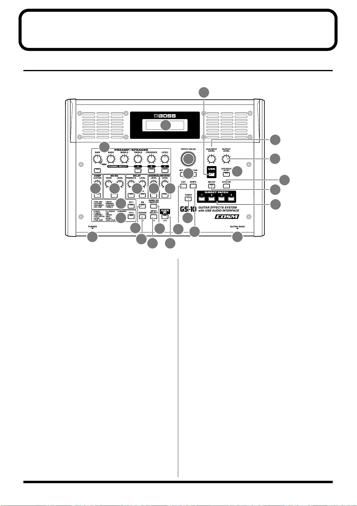
Panel Descriptions
Front Panel
fig.00-041
2
21
1
19
3 4 5 6 7
8
9
10
27 28
1. Display
A variety of information about the GS-10 appears here.
Normally, patch names are displayed.
2. PREAMP/SPEAKER (p. 21, p. 28)
(Preamp/Speaker Simulator)
GAIN Knob
Adjusts the degree of preamp distortion.
BASS Knob
Adjusts the sound quality of the preamp’s lowfrequency range.
MIDDLE Knob
Adjusts the sound quality of the preamp’s midrange.
TREBLE Knob
Adjusts the sound quality of the preamp’s highfrequency range.
PRESENCE Knob
Adjusts the sound quality in the preamp’s ultra-highfrequency range.
LEVEL Knob
Adjusts the preamp volume level.
PREAMP/SPEAKER On/Off Button
Press to change the settings.
CHANNEL SELECT Button
Switches the preamp channel.
12
13 14
11
15
16
22
20
24
23
26
25
17
18
3. COMP (Compressor) (p. 21, p. 31)
SUSTAIN Knob
Adjusts the compressor’s sustain effect (an effect that
keeps the sound playing).
COMP On/Off Button
Press to change the settings.
4. OD/DS (p. 21, p. 32)
(Overdrive/Distortion)
DRIVE Knob
Adjusts the degree of overdrive or distortion.
LEVEL Knob
Adjusts the overdrive/distortion volume level.
OD/DS On/Off Button
Press to change the settings.
5. DELAY (p. 21, p. 33)
FEEDBACK Knob
Adjusts the number of times the delay is repeated.
LEVEL Knob
Adjusts the volume level of the delay sound.
DELAY On/Off Button
Press to change the settings.
10

Panel Descriptions
TAP Button
Use this when setting the delay time with the tap input.
(p. 33)
6. CHORUS (p. 21, p. 34)
LEVEL Knob
Adjusts the volume level of the chorus sound.
CHORUS On/Off Button
Press to change the settings.
7. REVERB (p. 21, p. 34)
LEVEL Knob
Adjusts the volume level of the reverb sound.
REVERB On/Off Button
Press to change the settings.
8. FX-1 (p. 36)
FX-1 On/Off Button
Press to change the settings.
9. FX-2 (p. 41)
FX-2 On/Off Button
Press to change the settings.
10.
EQ (Equalizer) (p. 35)
EQ On/Off Button
Press when changing the settings.
11.
NAME/NS/MASTER Button (p. 24, p. 53)
Use for naming patches (NAME), setting the noise
suppressor (NS), and making the master settings
(MASTER).
12.
ASSIGN Button (p. 60)
Use this to make settings for the expression pedal and
control pedal.
13.
INPUT SELECT Button
Selects the input signal to which the effect is applied.
17.
EXIT Button
Use this to undo operations.
18.
WRITE Button
Press to store settings.
19.
AUX INPUT LEVEL Knob
Adjusts the volume of the input from the AUX INPUT
jack.
* Setting the input level too high may result in oscillation.
20.
OUTPUT LEVEL Knob
Adjusts the GS-10’s output level and the unit’s speaker
volume.
21.
USB Button (p. 78)
Used when making USB-related settings.
The indicator lights when the GS-10 is connected to
your computer.
22.
SPEAKER ON/OFF Button (p. 15)
Switches the GS-10’s speakers on and off.
23.
METER Button (p. 67)
Press to use the meter function.
24.
SYSTEM Button
Use for making settings for the GS-10’s overall
operating environment.
25.
TUNER Button (p. 64)
Press to use the tuner function.
26.
DIRECT PATCH Button (p. 18)
Allows you to directly call up your favorite patches
registered in the GS-10.
27.
PHONES Jack
Connect the stereo headphones here.
28.
GUITAR/BASS Jack
The guitar or bass is connected here.
14.
QUICK FX Button (p. 22)
Using the Quick Settings lets you complete the settings
procedure quickly and easily.
15.
PATCH/VALUE Dial
Use this when switching patches and changing the
values of settings.
16.
PARAMETER Buttons
Press to select parameters.
* To jump to the main parameters, hold down one of these
buttons while you press the other. With items for which there
aren’t that many parameters, the GS-10 jumps to the last (or
initial) parameter.
11
Panel Descriptions
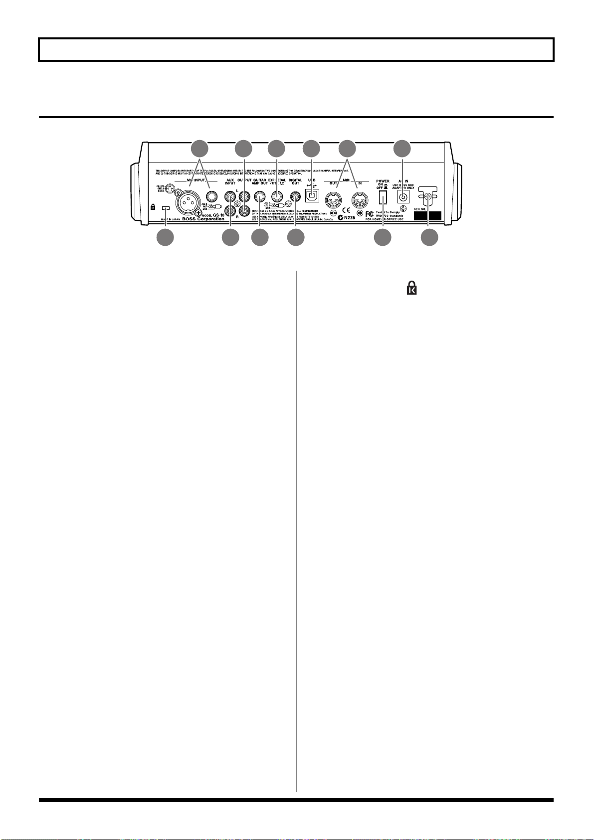
Rear Panel
fig.00-042
2 4 6
1. MIC INPUT Jack/Connector
Input jack/connector for use with mics. Both standard
TRS type and XLR type are provided.
* Use only one of these jacks at a time.
* Not compatible with phantom power.
2. AUX INPUT Jacks L/R
Used for connecting a CD player or similar audio
device, rhythm machine, sound module, or similar
devices.
3. OUTPUT Jacks L/R
Used for connecting to an audio set, recorder, mixer, or
similar equipment.
31 5 7
8
10
9
12.
Security Slot ( )
http://www.kensington.com/
1112
4. GUITAR AMP OUT Jack
Connect your guitar amp here.
5. EXP PEDAL/CTL 1,2
(Expression Pedal/Control Pedal 1,2) Jack
Connect an optional expression pedal (such as the EV-
5) or foot switch (such as the FS-5U) here.
6. DIGITAL OUT Connector
Outputs digital audio signals.
7. USB Connector
Use a USB cable to connect this connector to your
computer to exchange data between the GS-10 and the
computer.
8. MIDI IN/OUT Connector
Connect an external MIDI device to these connectors to
transmit and receive MIDI messages
9. POWER switch
Turns the power on and off.
10.
AC Adaptor Jack
Connect the included AC adaptor (BRC series) here.
11.
Cord Hook
Hook the AC adaptor cord here to prevent the adaptor
plug from being disconnected.
12
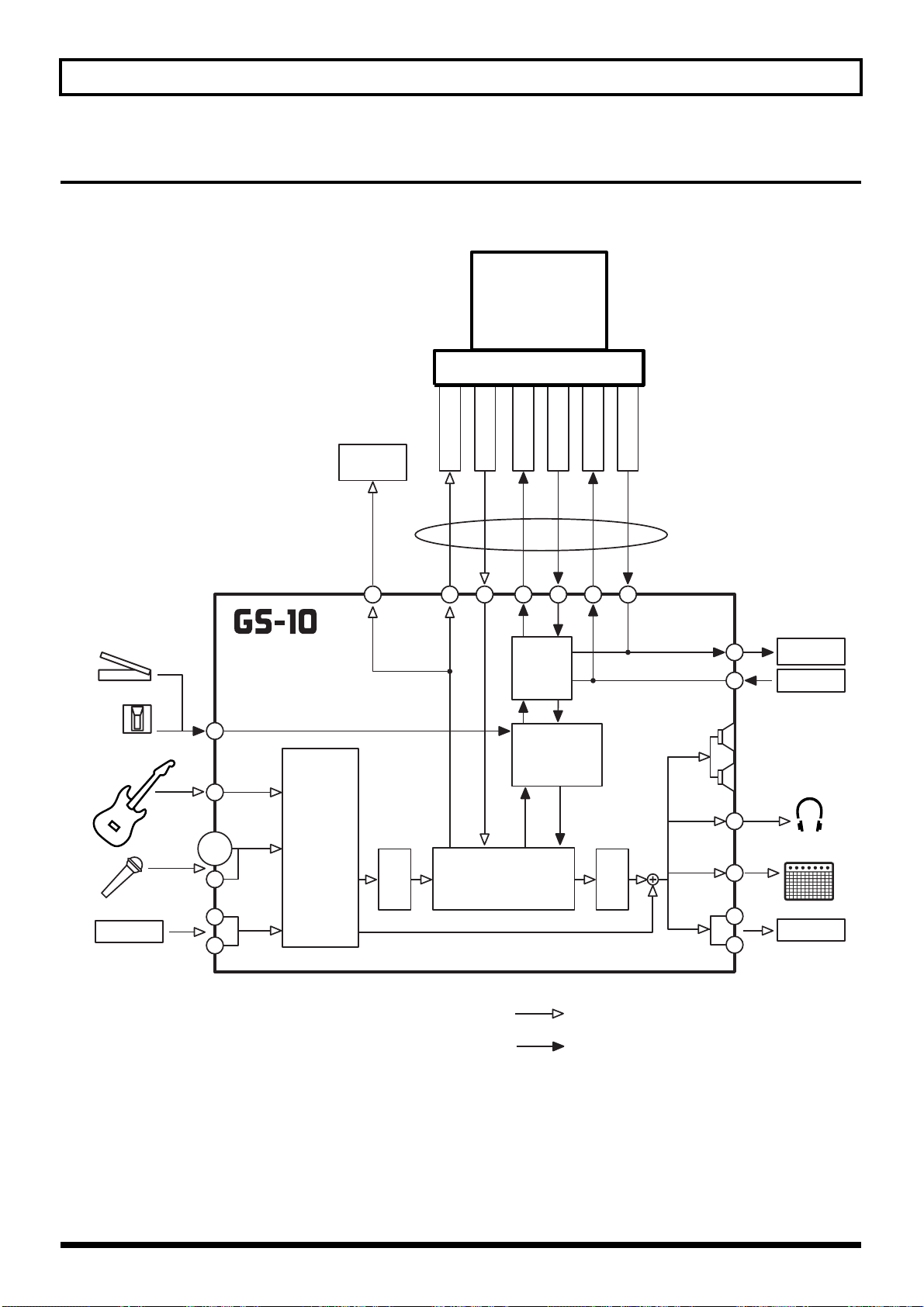
Signal Flow
fig.00-043
Panel Descriptions
Computer
Expression Pedal
Foot Switch
Guitar/Bass
Mic
CD/MD
EXP/CTL 1, 2
GUITAR/
BASS
MIC
INPUT
AUX
INPUT
INPUT
SELECT
Recorder
etc.
DIGITAL
GS-10 IN
OUT
CONTROL IN
GS-10 OUT
MIDI
SELECT
CONTROL
A/D D/A
MULTI EFFECTS
CONTROL OUT
MIDI IN
MIDI OUT
USB
MIDI OUT
MIDI IN
PHONES
AMP OUT
OUTPUT
GUITAR
Speaker
Sound
Module
Sequencer
Headphones
Guitar Amp
Mixer etc.
Audio signal
Control or MIDI signal
13
Chapter 1 Playing Sounds
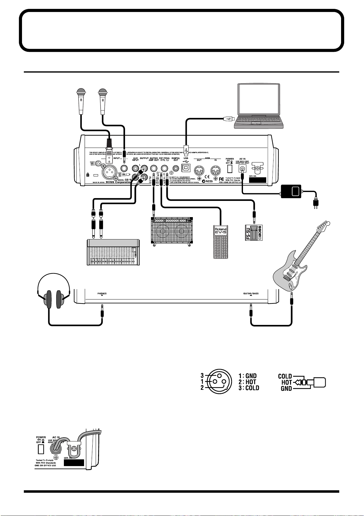
Making the Connections
fig.01-010
Mic
or
Computer
AC Adaptor
(BRC series)
Guitar Amp
Stereo Headphones
Mixer
* To prevent malfunction and/or damage to speakers or other
devices, always turn down the volume, and turn off the power
on all devices before making any connections.
* Turn up guitar amp and audio amp volume levels and the GS-
10’s OUTPUT LEVEL only after turning on the power to all
connected devices.
● To prevent the inadvertent disruption of power to your
unit (should the plug be pulled out accidentally), and to
avoid applying undue stress to the AC adaptor jack,
anchor the power cord using the cord hook, as shown in
the illustration.
fig.01-020
Guitar
or
Bass
Foot Switch
(FS-5U, etc.)
Expression Pedal
(Roland EV-5, etc.)
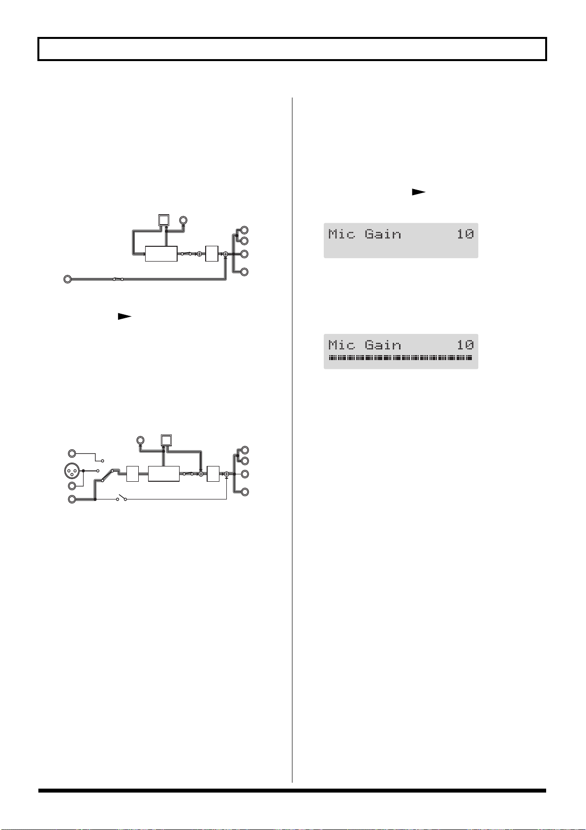
● This instrument is equipped with balanced (XLR/TRS)
type MIC INPUT jacks. Wiring diagrams for these jacks
are shown below. Make connections after first checking
the wiring diagrams of other mic you intend to connect.
fig.01-021
* Not compatible with phantom power.
● Howling could be produced depending on the location
of mics relative to speakers. This can be remedied by:
1. Changing the orientation of the mic(s).
2. Relocating mic(s) at a greater distance from
speakers.
3. Lowering volume levels.
14
Chapter 1 Playing Sounds
● When using the unit with an expression pedal connected
to the EXP PEDAL/CTL 1,2 jack, set Minimum Volume
to the “MIN” position.
● Use only the specified expression pedal (Roland EV-5;
optional). By connecting any other expression pedals,
you risk causing malfunction and/or damage to the unit.
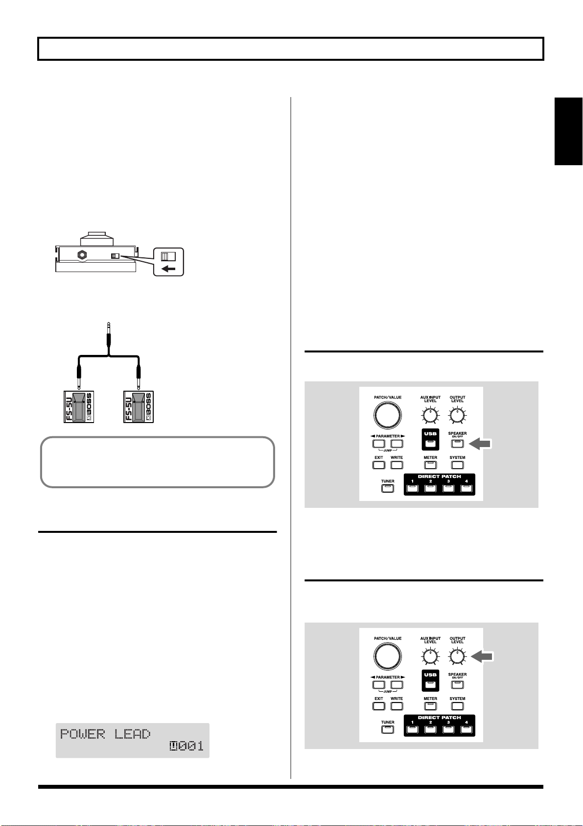
● When using the unit with a foot switch (FS-5U; optional)
connected to the EXP PEDAL/CTL 1,2 jack, set the
polarity switch as shown below.
fig.01-030
Polarity
Switch
* You can use the special (optional Roland) PCS-31 connector
cord to connect two foot switches.
fig.01-040
PCS-31
White Red
* Upon power-up, the patch most recently selected when the
power was last turned off is selected.
* This unit is equipped with a protection circuit. A brief interval
(a few seconds) after power up is required before the unit will
operate normally.
3. Next, turn on the power to guitar amp and audio
devices.
Turning Off the Power
1. Before turning off the power, confirm the following.
• Is the volume on the GS-10, your amp, and all other
connected devices turned down to the minimum level?
2. Turn off the power to guitar amp and audio devices.
3. Turn the GS-10’s power off.
Using the GS-10’s Speakers
Press [SPEAKER ON/OFF], causing the indicator to light.
fig.01-050
Section 1
When using the unit with a foot switch (the optional FS5U) connected to the EXP PEDAL/CTL 1,2 jack, make
the settings given on p. 59.
Turning On the Power
Once the connections have been completed, turn on power to
your various devices in the order specified. By turning on
devices in the wrong order, you risk causing malfunction
and/or damage to speakers and other devices.
1. Before turning on the power, confirm the following.
• Are all external devices properly connected?
• Is the volume on the GS-10, your amp, and all other
connected devices turned down to the minimum level?
2. Switch ON the POWER switch on the GS-10’s rear panel.
A few seconds later, the unit enters the ordinary
performance mode. The screen that appears at this point
is called the “Play screen.”
fig.01-050d
* When not using the GS-10’s speakers, press [SPEAKER ON/
OFF], so the indicator is off.
Adjusting the Output Level
Adjust the GS-10’s output level and speaker volume with the
OUTPUT LEVEL knob.
fig.01-060
15
Chapter 1 Playing Sounds
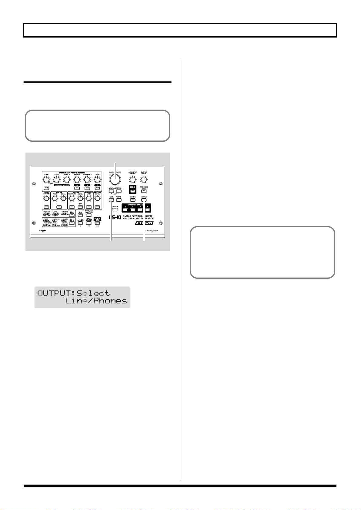
Setting Output Device (Amps) (OUTPUT SELECT)
Select the type of output device connected to the OUTPUT
jack or GUITAR AMP OUT jack.
To derive the maximum performance from the GS-10, be
sure to make the correct setting for OUTPUT SELECT,
the one that’s most suitable for your setup.
fig.01-061
2
13
1. Press [SYSTEM], causing the indicator to light.
The Output Select settings screen appears.
fig.01-070d
Combo Return
Use this setting when connecting to RETURN with a
combo amp.
Stack Return
Use this setting when connecting to RETURN of a stack
amp or rack mounted power amp.
3. Press [EXIT] to return to the Play screen.
* Set OUTPUT SELECT as shown below, when the PREAMP/
SPEAKER type (p. 29) is set to CONCERT 810, SESSION,
BASS 360, T.E., B-MAN, FLIP TOP, Bass Clean, Bass
Crunch, Bass HiGain, or Mic Preamp.
When connecting to an audio amp or similar equipment:
Line/Phones
When connecting to a guitar amp:
Combo Amp or Combo Return
When connecting to a bass amp:
Stack Amp or Stack Return
Guitar Tuning
You can use the GS-10’s built-in “tuner function” to tune
your guitar.
For instructions on using this function, refer to “Tuning
the Guitar” (p. 64).
2. Turn the PATCH/VALUE dial to select the type of
device connected to the OUTPUT jack or GUITAR
AMP OUT jack.
Line/Phones
Set this when connecting the OUTPUT jack to an audio
set or when connecting a recorder for recording.
Use this setting also when using the GS-10’s speakers or
headphones.
Combo AMP
Use this setting when connecting to the guitar input of a
combo amp (where the amp and speaker or speakers are
combined in a single unit).
Stack AMP
Use this setting when connecting to the guitar input of a
stack-type guitar amp (where the amp and speaker or
speakers are separated).
16
Chapter 1 Playing Sounds
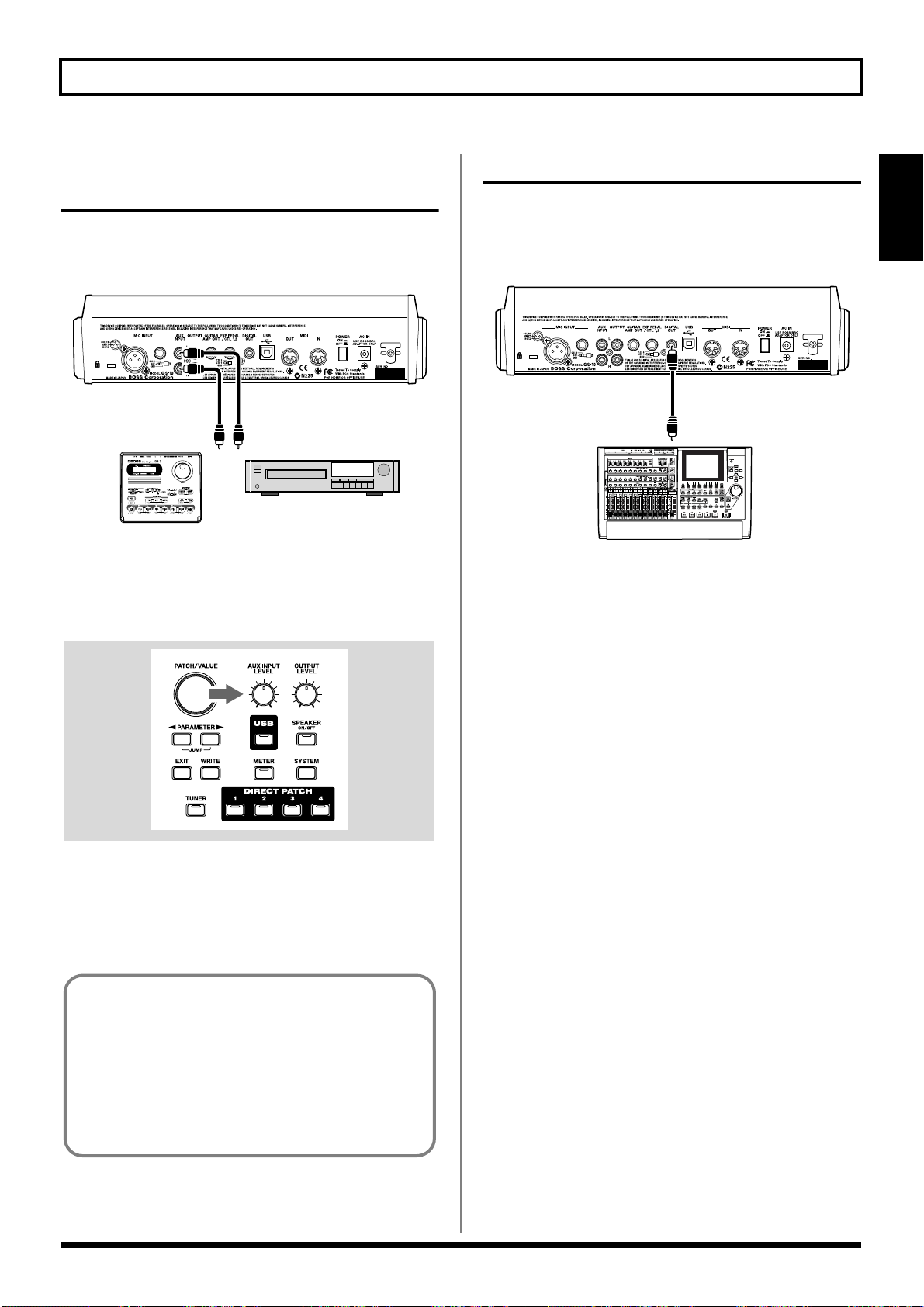
Connecting Audio Devices to the AUX INPUT Jack
When using a CD or MD player, rhythm machine, or similar
device for practice, connect these device to the AUX INPUT
jack on the rear panel.
fig.01-080
CD/MD Player
Rhythm Machine
Use the AUX INPUT knob on the front panel to adjust the
input volume level for AUX INPUT.
* Setting the input level too high may result in oscillation.
fig.01-090
Using the Digital Output
Digital signals are output from the DIGITAL OUT connector
on the rear panel. You can connect this directly to the digital
in connector of a digital recorder or other device and record
with no degradation in sound quality.
fig.01-100
DIGITAL IN
Digital Recorder
Section 1
The input sounds from the AUX INPUT jack are mixed with
the guitar sounds within the GS-10, making this a convenient
feature when using the GS-10’s speakers or headphones.
* The mixed sound is not output from DIGITAL OUT.
AUX INPUT
You can set INPUT SELECT and use USB to record the
input sounds from the AUX INPUT jack to your
computer, and record to a recorder using DIGITAL OUT.
You can also add effects to the sounds input from the
AUX INPUT jack.
For instructions on setting INPUT SELECT, refer to
“Selecting the Input (INPUT SELECT)” (p. 19).
17
Chapter 2 Creating Your Own Favorite Tones (Patches)
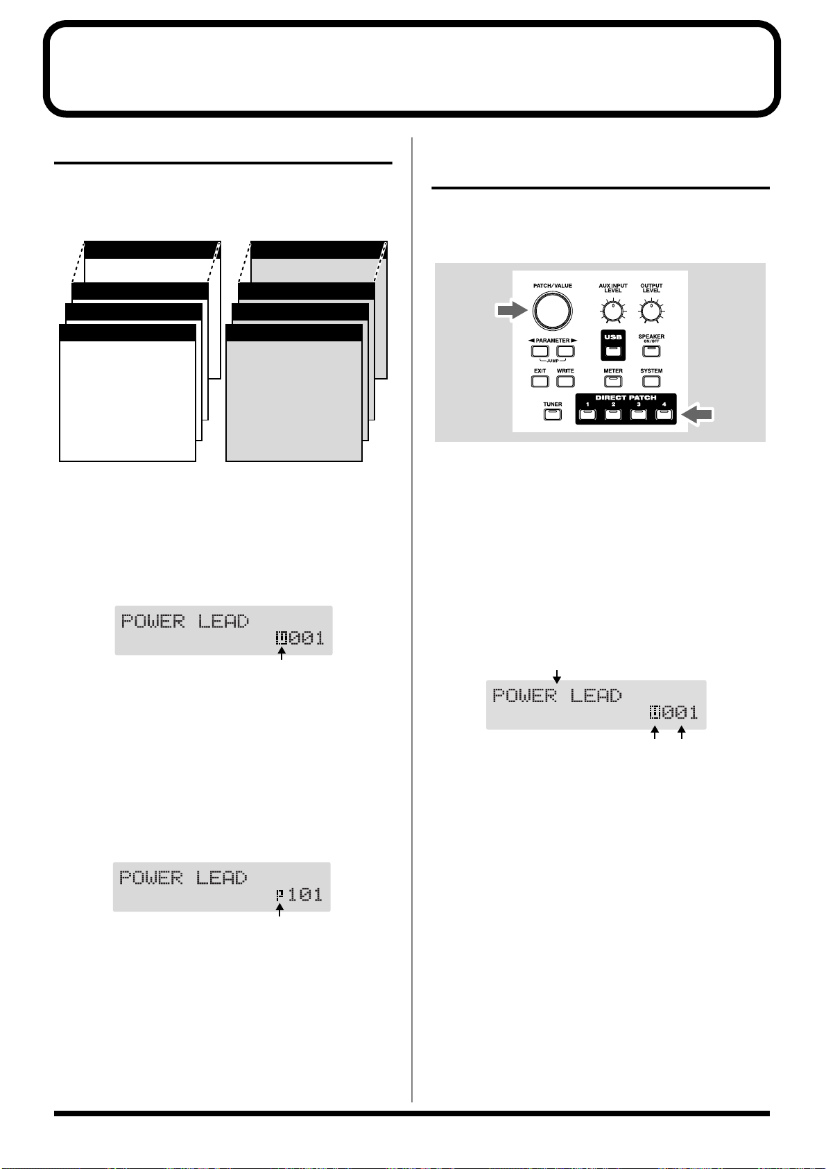
What is a Patch?
The GS-10 can store 200 combinations (or “sets”) of effects
and parameter settings. Each of these sets is called a “patch.”
Patches include both User patches and Preset patches.
fig.02-010
U100
● Patch Name
● Input Select
U003
● Effects
U002
● Assign 1–8
● Master
U001
● Noise Suppressor
● Patch Name
● Effect Chain
● Input Select
● Effects
● Assign 1–8
● Master
● Noise Suppressor
● Effect Chain
User Patches
User Patches (U001–U100)
Newly created effects settings are saved in the User patches.
*A “U” appears in the display when a User patch is being used.
fig.02-020d
P200
● Patch Name
● Input Select
P103
● Effects
P102
● Assign 1–8
● Master
P101
● Noise Suppressor
● Patch Name
● Effect Chain
● Input Select
● Effects
● Assign 1–8
● Master
● Noise Suppressor
● Effect Chain
Preset Patches
How to Select Patches (Patch Change)
When the Play screen is showing in the display, you can
switch patches using the PATCH/VALUE dial or DIRECT
PATCH [1]–[4] (p. 27).
fig.02-040
* If you want to set a limit to the number of patches that can be
selected with the PATCH/VALUE dial, change the system
function settings (p. 65).
* Settings currently being edited are cleared when you switch
patches. If you want to save the setting changes you’ve made,
use the Write procedure (p. 25).
About the Display Indication
Preset Patches (P101–P200)
The Preset patches contain effect settings that really help
bring out the special characteristics of the GS-10.
Although you cannot overwrite the Preset patches with your
own settings, you can change (edit) a Preset patch’s settings,
then save the result as a User patch. (p. 25)
*A “p” appears in the display when a Preset patch is being
used.
fig.02-030d
The following information appears in the Play screen.
fig.02-050d
Patch Name
User/Preset Number
If the Patch Does Not Switch
On the GS-10, you cannot switch patches in any screen other
than the Play screen. Press [EXIT] to return to the Play screen
(p. 15).
18
Chapter 2 Creating Your Own Favorite Tones (Patches)
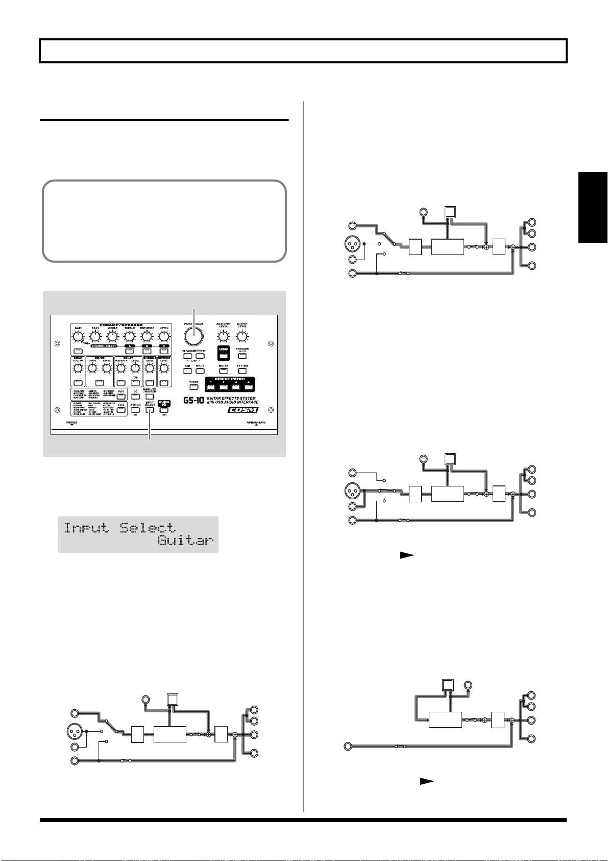
Selecting the Input (INPUT SELECT)
This selects the input signal to which the effects are added.
This is also used for setting the type of device connected to
the input connector.
To derive the maximum performance from the GS-10, be
sure to make the correct setting for INPUT SELECT, the
one that’s most suitable for your setup.
You may not be able to achieve the expected effect if this
is not set correctly.
fig.02-051
2
1
1. Press [INPUT SELECT].
The Input Select settings screen appears.
fig.02-060d
2. Turn the PATCH/VALUE dial to change the settings.
Guitar:
You can add effects to the signals input from the
GUITAR/BASS INPUT connector (when a guitar is
connected). Signals from MIC INPUT are disregarded,
and the signals input to the GS-10 from the USB or AUX
INPUT connectors are mixed with the effect output.
fig.02-070
DIGITAL
USB
OUT
D/A
L
R
OUTPUT
GUITAR
AMP OUT
PHONES
GUITAR/
BASS
MIC
INPUT
AUX
INPUT
A/D
MULTI
EFFECTS
Bass:
You can add effects to the signals input from the
GUITAR/BASS jack (when a bass is connected). Signals
from MIC INPUT are disregarded, and the signals input
to the GS-10 from the USB or AUX INPUT connectors are
mixed with the effect output.
fig.02-080
DIGITAL
USB
OUT
D/A
L
R
OUTPUT
GUITAR
AMP OUT
PHONES
GUITAR/
BASS
MIC
INPUT
AUX
INPUT
A/D
MULTI
EFFECTS
* Depending on the type of bass guitar you are using, you may
not be able to achieve the intended effect if the input level to the
GS-10 is excessively high.
In such cases, lower the volume or tone of your bass guitar.
Microphone:
You can add effects to the signals input from the MIC
INPUT connector. Signals from GUITAR/BASS jack are
disregarded, and the signals input to the GS-10 from the
USB or AUX INPUT connectors are mixed with the effect
output.
fig.02-090
DIGITAL
USB
OUT
D/A
L
R
OUTPUT
GUITAR
AMP OUT
PHONES
GUITAR/
BASS
MIC
INPUT
AUX
INPUT
A/D
MULTI
EFFECTS
* After setting INPUT SELECT to Microphone, you can press
PARAMETER [ ] to set the mic gain (p. 20).
USB (Gtr/Mic):
You can add effects to the signals input from the USB
connector (for sounds in the guitar and vocal registers).
Signals from GUITAR/BASS and MIC INPUT are
disregarded, and the signals input to the GS-10 from the
AUX INPUT connector are mixed with the effect output.
fig.02-100
DIGITAL
USB
OUT
L
OUTPUT
MULTI
EFFECTS
AUX
INPUT
* After setting INPUT SELECT to USB (Gtr/Mic), you can
press PARAMETER [ ] to set the USB input level (p. 78).
D/A
R
GUITAR
AMP OUT
PHONES
Section 2
19
Chapter 2 Creating Your Own Favorite Tones (Patches)
USB (Bass):
You can add effects to the signals input from the USB
connector (for sounds in the bass and similar registers).
Signals from GUITAR/BASS INPUT and MIC INPUT
are disregarded, and the signals input to the GS-10 from
the AUX INPUT connector are mixed with the effect
output.
fig.02-110
DIGITAL
USB
OUT
L
OUTPUT
R
GUITAR
AMP OUT
PHONES
AUX
INPUT
MULTI
EFFECTS
D/A
* After setting INPUT SELECT to USB (Bass), you can press
PARAMETER [ ] to set the USB input level (p. 78).
AUX:
This setting is used when selecting the input signal from
the AUX INPUT connector. Signals input from the
GUITAR/BASS INPUT and MIC INPUT are
disregarded, and the signals input to the GS-10 via USB
are mixed with the effect output.
fig.02-120
DIGITAL
USB
OUT
D/A
L
R
OUTPUT
GUITAR
AMP OUT
PHONES
GUITAR/
BASS
MIC
INPUT
AUX
INPUT
A/D
MULTI
EFFECTS
Setting the Mic Input Level (MIC GAIN)
This sets the mic input level when INPUT SELECT is set to
Microphone.
* The mic gain setting is a global setting used by all patches.
1. Press PARAMETER [ ].
The MIC GAIN settings screen appears in the display.
fig.02-130d
2. Adjust the gain by turning the PATCH/VALUE dial
while picking up sounds with the mic.
Adjust the level so that the level meter does not fluctuate
beyond the maximum allowable level.
fig.02-140d
* Set the volume for the sound being miked (acoustic guitar,
vocals, etc.) to the level to be used in performance.
* Setting the mic gain too high may result in oscillation.
3. Press [EXIT] to return to the Play screen.
20
Chapter 2 Creating Your Own Favorite Tones (Patches)
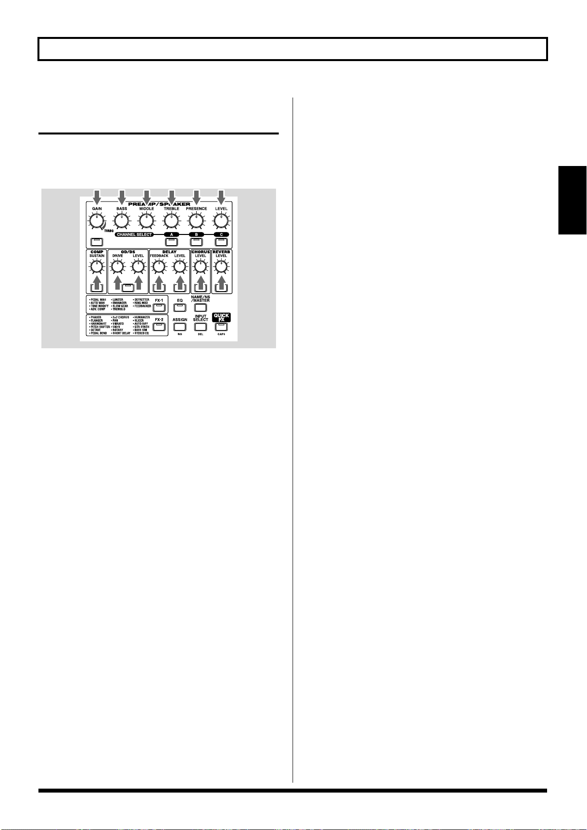
Adjusting the Tones with the Knobs
The GS-10 panel features 13 knobs for adjusting effect tones.
You can use these knobs to make slight adjustments to tones
in the selected patch quickly and easily.
fig.02-150
PREAMP GAIN:
Adjusts the degree of preamp distortion. The distortion gets
stronger as the knob is turned to the right.
OD/DS (Overdrive/Distortion) DRIVE
Adjusts the degree of overdrive or distortion. The distortion
appears stronger as the knob is turned to the right.
OD/DS (Overdrive/Distortion) LEVEL:
Adjusts the overdrive/distortion volume level. The volume
increases as the knob is turned to the right.
DELAY FEEDBACK:
Adjusts the number of times the delay is repeated. The
number of repeats increases as the knob is turned to the
right.
DELAY LEVEL:
Adjusts the volume level of the delay sound. The delay
sound increases as the knob is turned to the right.
CHORUS LEVEL:
Adjusts the volume level of the chorus sound. The chorus
sound increases as the knob is turned to the right.
REVERB LEVEL:
Adjusts the volume level of the reverb sound. The reverb
sound increases as the knob is turned to the right.
Section 2
PREAMP BASS:
Adjusts the sound quality of the preamp’s low-frequency
range. The low frequencies are boosted as the knob is turned
to the right.
PREAMP MIDDLE:
Adjusts the sound quality of the preamp’s midrange. The
midrange frequencies are boosted as the knob is turned to
the right.
PREAMP TREBLE:
Adjusts the sound quality of the preamp’s high-frequency
range. The high frequencies are boosted as the knob is turned
to the right.
PREAMP PRESENCE:
Adjusts the sound quality in the preamp’s ultra-highfrequency range. The ultra-high frequencies are boosted as
the knob is turned to the right.
PREAMP LEVEL:
Adjusts the preamp volume level. The volume increases as
the knob is turned to the right.
COMP (Compressor) SUSTAIN:
Adjusts the compressor’s sustain effect (an effect that keeps
the sound playing). The effect is strengthened as the knob is
turned to the right.
21
Chapter 2 Creating Your Own Favorite Tones (Patches)
2 51
3
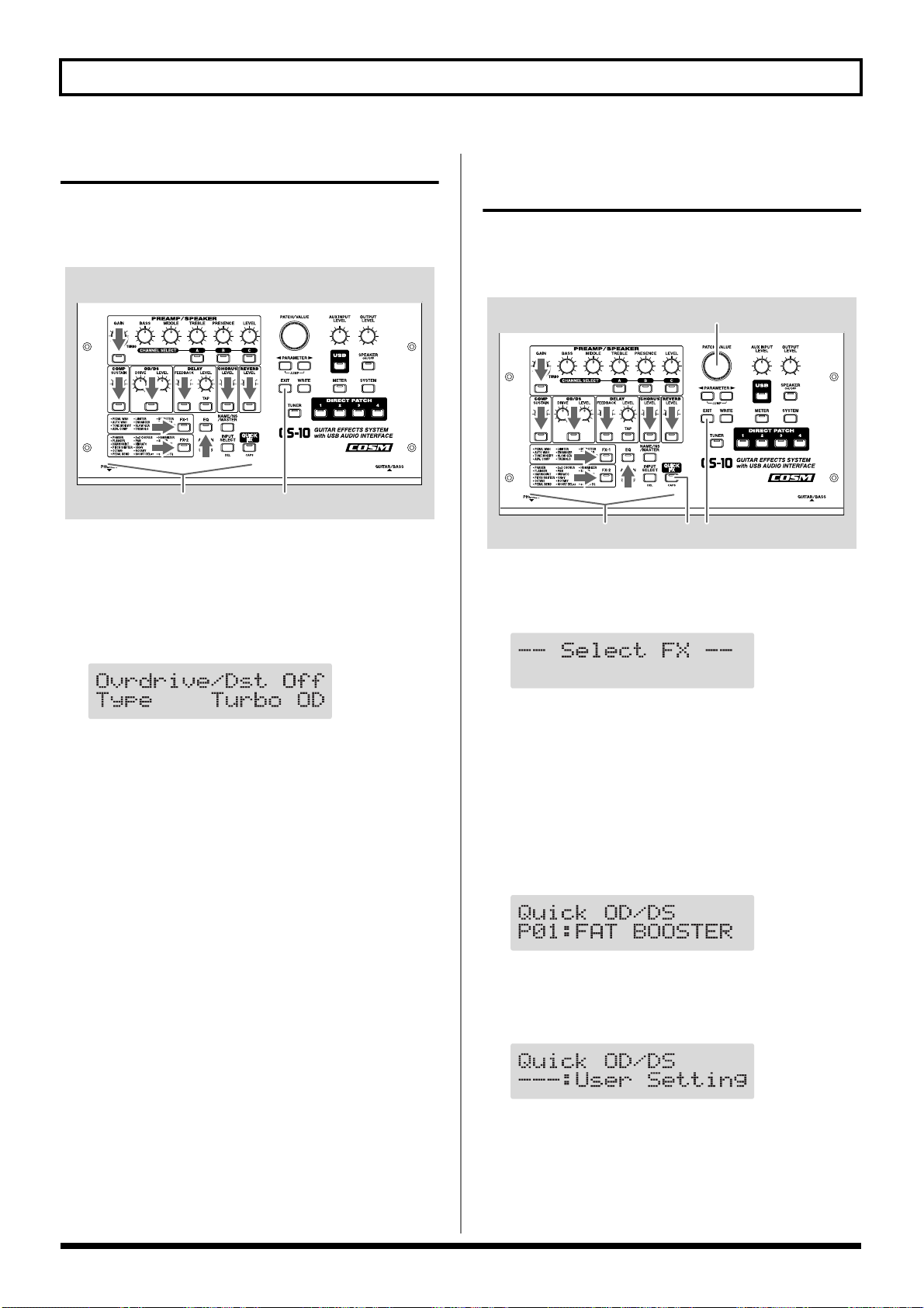
Turning the Effect On and Off
The GS-10’s internal effects are switched on and off with
button controls. The indicator for an effect’s ON/OFF button
lights up when the effect is enabled.
fig.02-160
1,2,3 4
1. Press the ON/OFF button for the effect you want to be
able to switch on and off.
The settings for the selected effect appear in the display.
* With FX-1 and FX-2, the settings for the currently selected
effect are shown.
fig.02-170d
Setting the Effects Simply (QUICK FX)
Each effect includes prepared sample settings called “Quick
Settings.” You can easily create new effect sounds just by
selecting and combining these Quick Settings.
fig.02-171
1. Press [QUICK FX].
The effects selection screen appears in the display.
fig.02-180d
2. Press the ON/OFF button again to switch the effect on
or off.
* The effect name flashes in the display when that effect is
disabled.
3. To select another effect to be switched on and off,
repeat Steps 1 and 2.
4. Press [EXIT] to return to the Play screen.
* If you want to save a tone with the settings you’ve made, use
the Write procedure (p. 25) to save the tone to a User patch.
* Performing Step 1 while editing an effect takes you to the
status following Step 2.
2. Press the ON/OFF button for the effect you want to
select for Quick Settings.
The name of the effect being set with Quick Settings
appears in the upper row of the display, and the “Quick
Settings Name” currently selected for that effect appears
in the lower row of the display.
fig.02-190d
* The following appears in the display immediately after patches
are changed or when the settings in Quick settings are
changed by editing the parameters.
fig.02-200d
* The upper row of the display flashes when the selected effect is
switched off. Even when using the Quick Settings, you can
switch effects on and off with the effect ON/OFF buttons.
22
Chapter 2 Creating Your Own Favorite Tones (Patches)
1 61
23
3. Rotate the VALUE dial to select the Quick Setting you
want.
The tone switches to that of the selected sample settings.
* You can select “—: User Setting” to return the settings to
their condition prior to selecting the Quick Settings.
4. To select Quick Settings for another effect, repeat Steps
2 and 3.
* Even after performing this procedure, the settings selected in
Step 3 are maintained as is and carried over to the Quick
Settings for the next effect.
5. Press [EXIT] to return to the Play screen.
* If you want to save a tone with the settings you’ve made, use
the Write procedure (p. 25) to save the tone to a User patch.
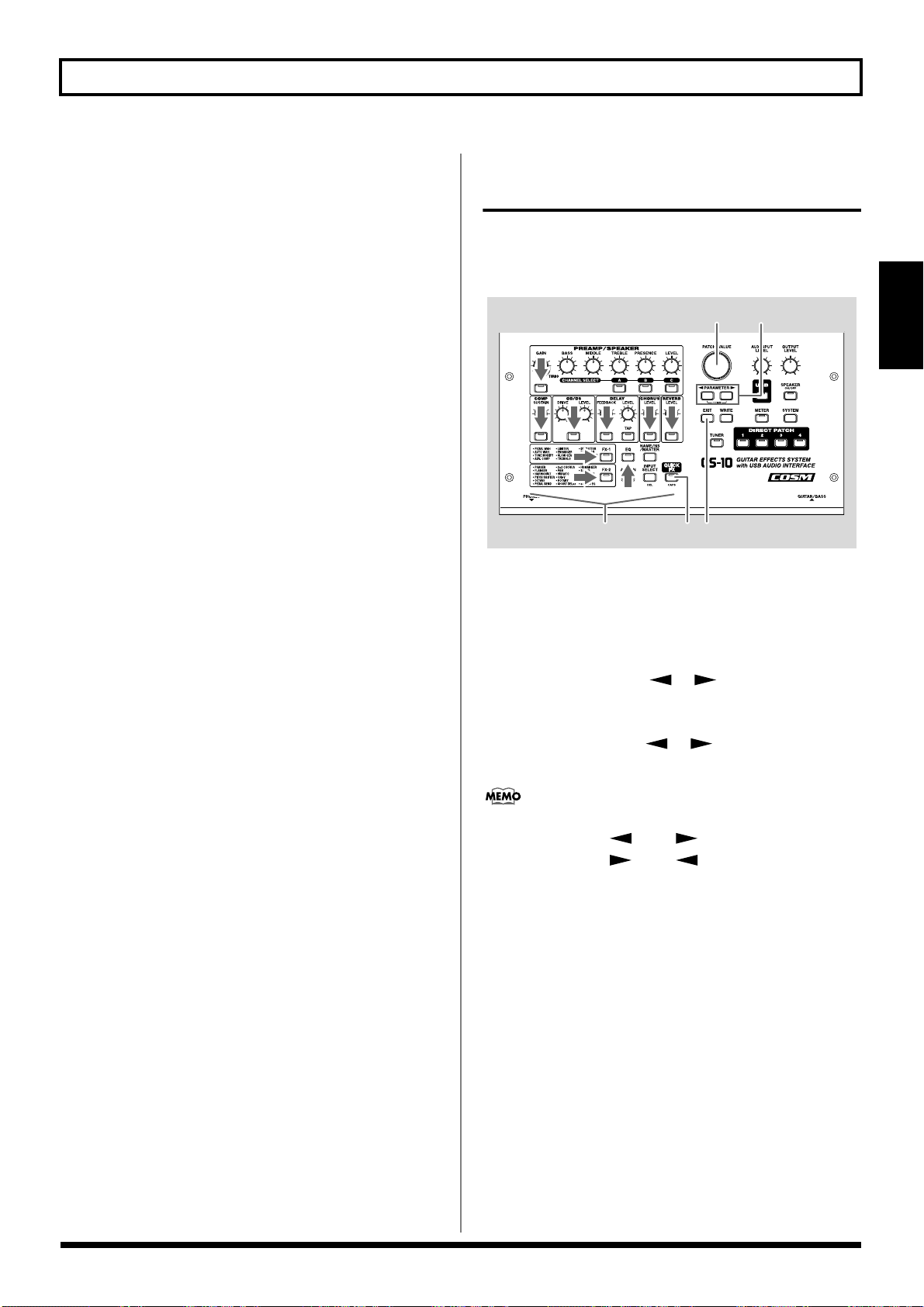
Making More Precise Effect Settings
Each effect comprises several different kinds of parameters.
You can more precisely create the sounds you want by
editing each of these parameters individually.
fig.02-210
1. Press the on/off button for the effect with the settings
you want to change.
The parameters for the selected effect appear in the
display.
Section 2
2. Press PARAMETER [ ] [ ] to select the
parameter whose settings are to be changed.
When more than one parameter is shown in the display,
press PARAMETER [ ] [ ] to move the cursor to
the parameter to be set.
You can jump to the core parameters by pressing
PARAMETER [ ] (or [ ]) while holding down
PARAMETER [ ] (or [ ]). With items for which
there aren’t that many parameters, the GS-10 jumps to
the last (or first) parameter.
3. Rotate the VALUE dial to change the value of a setting.
4. Repeat Steps 2 and 3 for any other parameter settings
you want to change.
5. If you further want to change parameter settings in any
other effects, repeat Steps 1 through 4.
6. Press [EXIT] to return to the Play screen.
* If you want to save a tone with the settings you’ve made, use
the Write procedure (p. 25) to save the tone to a User patch.
23
Chapter 2 Creating Your Own Favorite Tones (Patches)
3 1
22
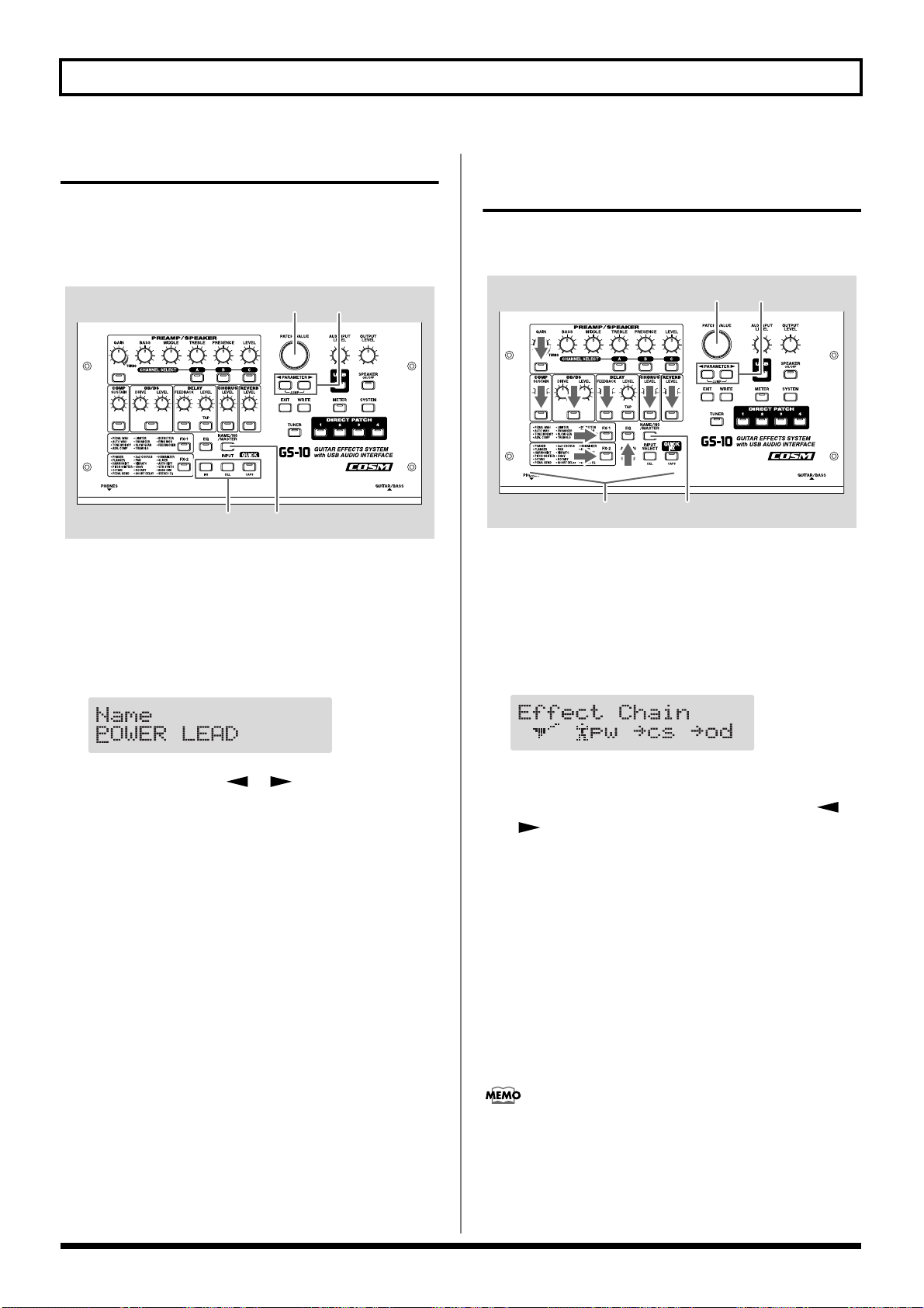
Naming Patches
Each patch can be given a name (Patch Name) consisting of
up to sixteen characters. You’ll probably want to take
advantage of this feature by assigning names that suggest the
sound you’ll obtain, or the song in which it’ll be used.
fig.02-220
23
13
1. Press [NAME/NS/MASTER] so that the Name edit
screen appears in the display.
* With each press of [NAME/NS/MASTER], you move to the
next item that can be set, in this order:
Name → Noise Suppressor → Master → Foot Volume →
Effect Chain.
fig.02-230d
Changing the Connection Order of Effects (Effect Chain)
Here’s how you can change the order in which the effects are
connected.
fig.02-240
1. Press [NAME/NS/MASTER] until “Effect Chain”
appears in the display.
* With each press of [NAME/NS/MASTER], you move to the
next item that can be set, in this order:
Name → Noise Suppressor → Master → Foot Volume →
Effect Chain.
fig.02-250d
2. Press PARAMETER [ ] [ ] to move the cursor to
the text area you want to edit.
3. Rotate the PATCH/VALUE dial to change the
characters.
* You can use the following functions when changing text
characters.
CAPS: Switches the character at the cursor position
between upper and lower case.
INS: Inserts a blank space at the cursor position.
DEL: Deletes the character at the cursor position and
shifts the characters following it to the left.
4. If you want to edit names further, repeat Steps 2 and 3.
5. If you want to save the sequence you’ve set up, use the
Write procedure (p. 25) to save it to a User patch.
Press [EXIT] to return to the Play screen.
* Effects are shown in lowercase letters when turned off.
2. Use the PATCH/VALUE dial or PARAMETER [ ]
[] to move the cursor to the point where you want
to have an effect inserted.
3. Press the On/Off button for the effect you want to
insert.
The selected effect is inserted at the cursor position.
* Use [ASSIGN] to assign Foot Volume.
4. If you want to change the sequence further, repeat
Steps 2 and 3.
5. If you want to save the sequence you’ve set up, use the
Write procedure (p. 25) to save it to a User patch.
Press [EXIT] to return to the Play screen.
Effects can be switched on and off even while making
the settings for the connection order (excluding FV, NS,
and USB).
With effects appearing to the left and right of the cursor,
the ON/OFF button corresponding to the effect can be
pressed to turn them on/off.
24
Chapter 3 Saving the Tones You Have Created
2,4
3
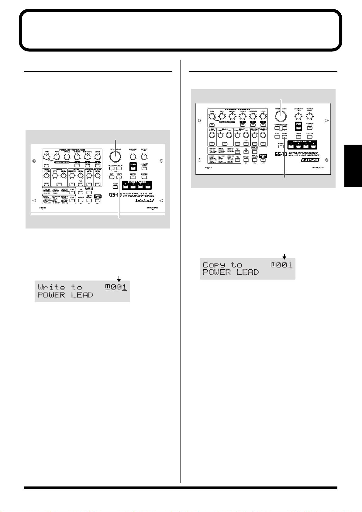
Storing Patches (PATCH WRITE)
When you want to keep a tone created with the Quick
Settings or a tone with altered parameter values, use the
“Write procedure” to save it to a User patch.
* If the power is turned off, or if the tone is switched (Patch
Change; p. 18) before you’ve carried out the Write procedure,
the newly created tone will be discarded.
fig.03-010
2
1,3
1. Press [WRITE].
The screen for specifying the save-destination User patch
appears in the display.
fig.03-020d
Save-destination patch
Copying Patches
You can copy a Preset or User patch to another User patch.
fig.03-030
Section 3
1. Select the copy-source patch (refer to “How to Switch
Patches”; p. 18).
2. Press [WRITE].
The screen for specifying the copy-destination patch
number appears in the display.
fig.03-040d
Copy-destination patch
2. Rotate the VALUE dial to select the save-destination
User patch.
* This step is unnecessary if the current User patch is
acceptable.
* To cancel the Write procedure, press [EXIT]. The Play screen
returns to the display.
3. Press [WRITE].
The GS-10 switches to the write-destination patch, and
you’re returned to the Play screen.
* The sound of the patch previously stored at the write
destination will be lost once the write is executed.
3. Rotate the PATCH/VALUE dial to select the copy-
destination User patch.
* To cancel the copy, press [EXIT]. The Play screen returns to
the display.
4. Press [WRITE].
The GS-10 switches to the copy-destination patch, and
you’re returned to the Play screen.
* The sound of the patch previously stored at the copy
destination will be lost once the copy is executed.
25
Chapter 3 Saving the Tones You Have Created
2,4
3
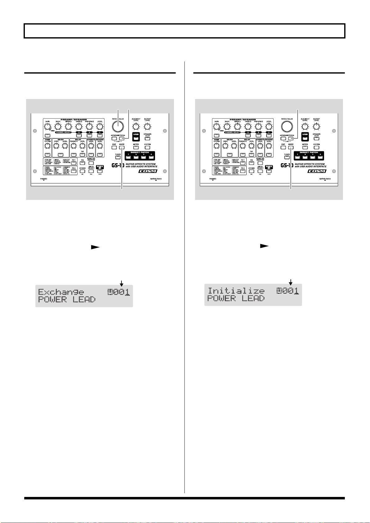
Exchanging Patches
On the GS-10, you can “swap” or exchange the positions of
two User patches. The following explains how this is done.
fig.03-050
4 3
2,5
1. Select the exchange source patch.
* Refer to “Patch Change” (p. 18).
2. Press [WRITE].
3. Press PARAMETER [ ].
The screen for specifying the exchange-destination patch
number appears in the display.
fig.03-060d
Exchange-destination patch
Initializing Patches
You can return (initialize) the User patches to their original
standard settings.
fig.03-061
1. Select the User patch you want to initialize.
* Refer to “Patch Change” (p. 18).
2. Press [WRITE].
3. Press PARAMETER [ ] twice.
The screen for specifying the initialize-destination patch
number appears in the display.
fig.03-062d
User patch to be initialized
4. Rotate the PATCH/VALUE dial to select the exchange
destination User patch.
* To cancel the exchange, press [EXIT]. The Play screen returns
to the display.
5. Press [WRITE].
The patch stored in the exchange source memory
location and the patch stored in the exchange destination
memory location are exchanged, and you’re returned to
the Play screen.
* You can use the PATCH/VALUE dial to change the selection
of the User patch to be initialized.
* To cancel the initialization, press [EXIT]. The Play screen
returns to the display.
4. Press [WRITE].
The GS-10 switches to the initialized patch, and the Play
screen returns to the display.
* The tones stored in patches are lost once the initialization is
executed.
26
Chapter 3 Saving the Tones You Have Created
2,4
1,3
Copy-destination channel
Copy-source channel
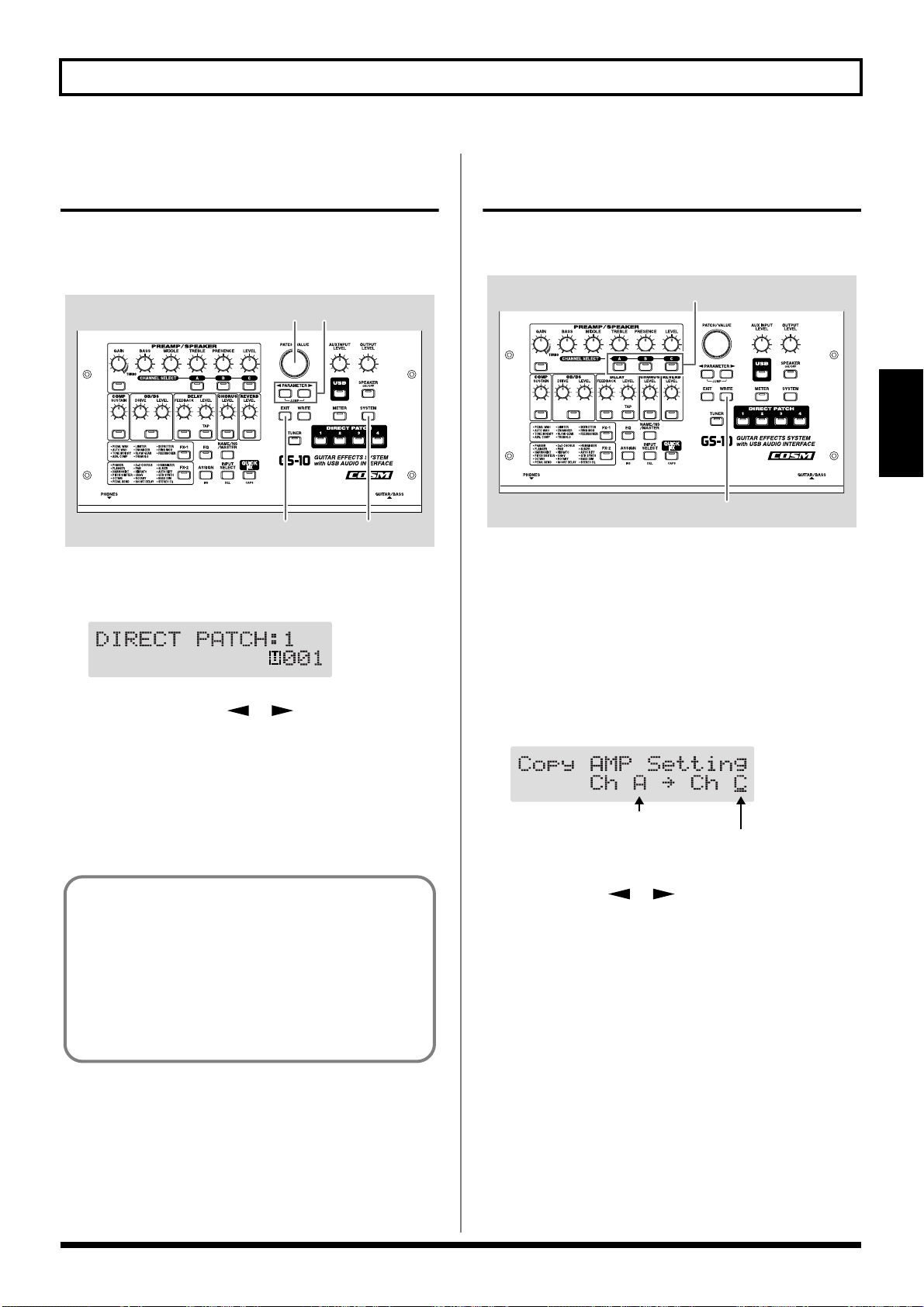
Registering Your Favorite Patches (DIRECT PATCH)
You can register preferred patches to DIRECT PATCH [1]–[4]
and then press these buttons to call up the corresponding
patches directly.
fig.03-070
32
4 1
1. Press [SYSTEM] a number of times until “DIRECT
PATCH” is displayed.
fig.03-080d
Copying the PREAMP/SPEAKER Settings to Another Channel
You can take the PREAMP/SPEAKER settings for one
channel and copy them to another channel.
fig.03-090
Section 3
1. Select the copy-source channel.
2. Press [WRITE].
3. Press CHANNEL SELECT [A]–[C] to select the copy-
destination channel.
The channel copy screen appears in the display.
2. Press PARAMETER [ ] [ ] to select the number
of the DIRECT PATCH button to which you want to
register the patch.
3. Use the PATCH/VALUE dial to select the patch you
want to register.
4. Press [EXIT] to return to the Play screen.
You can also register patches by selecting the patch in
the Play screen, then pressing one of the
[1]–[4] buttons after pressing the [WRITE] button. In this
case, the patch appearing in the display is registered.
* When a patch is registered using this method, the current
settings are also saved along with the patch when it’s
registered. If you want to register only the patch, use the
regular registration method.
DIRECT PATCH
* If you press the button for the same channel as the copy source,
a channel other than the copy-source channel is selected for the
copy destination.
fig.03-100d
* To change the copy-source or copy-destination channel, press
PARAMETER [ ] [ ] to move the cursor to the copysource or copy-destination channel, then press CHANNEL
SELECT [A]–[C].
You can alternatively rotate the PATCH/VALUE dial to
change the channel at the cursor position.
* When the copy-source channel is changed, the tone is changed
as well.
* To cancel the copy, press [EXIT]. The Play screen returns to
the display.
4. Press [WRITE].
The settings are copied.
* If you want to keep a tone for which you have made settings,
use the “Write procedure” (p. 25) to save it to a User patch.
27
Chapter 4 Introduction to Effects and Parameters
In this chapter you will find detailed descriptions for each of
the GS-10’s onboard effects, and the parameters used to
control them.
The sound being input to each effect is called the “direct
sound,” and the sound modified by the effect is called the
“effect sound.”
* Setting values for gain– and volume–related parameters in the
effects too high may result in oscillation.
To derive the maximum performance from the GS-10,
be sure to make the correct setting for INPUT SELECT
(p. 19), the one that’s most suitable for your setup.
You may not be able to achieve the expected effect if
this is not set correctly.
* Depending on the type of bass guitar you are using, you
may not be able to achieve the intended effect if the input
level to the GS-10 is excessively high. In such cases, lower
the volume or tone of your bass guitar.
The trademarks listed in this document are trademarks
of their respective owners, which are separate companies
from BOSS. Those companies are not affiliated with
BOSS and have not licensed or authorized BOSS’s GS-10.
Their marks are used solely to identify the equipment
whose sound is simulated by BOSS’s GS-10.
PREAMP/SPEAKER (Preamp/ Speaker Simulator)
COSM technology plays an indispensable role in simulating
the distinguishing characteristics of various guitar amps in
the “Preamp” section, and is also used to simulate various
speaker sizes and cabinet constructions in the “Speaker
Simulator.”
Parameter Value
On/Off Off, On
CH Select A, B, C
Type refer to p. 29
Gain 0–120
Bass 0–100
Middle 0–100
Treble 0–100
Presence 0–100
Level 0–100
Bright Off, On
Gain SW Low, Middle, High
SP Type (*) Off, Original, 1x8”, 1x10”, 1X12”,
1X15”, 1X18”, 2X12”, 2X15”,
4X10”, 4X12”, 8X10”, 8X12”,
Custom 1, Custom 2
Mic Type (*) DYN57, DYN421, CND451,
CND87, FLAT
Mic Dis. (*) Off Mic, On Mic
Mic Pos. (*) Center, 1–10
Mic Level (*) 0–100
Direct Level (*) 0–100
(*) No effect when OUTPUT Select is set to “Line/Phones.”
On/Off (Effect On/Off)
Turns the PREAMP/SPEAKER effect on/off.
CH Select (Channel Select)
Selects the preamp channel whose settings are to be changed.
28
Chapter 4 Introduction to Effects and Parameters
Type
This sets the type of the guitar preamp.
JC-120 This is the sound of the Roland JC-120.
Jazz Combo This is a sound suited to jazz.
Full Range
Warm Clean This gives a mellow, clean sound.
Clean TWIN This models a Fender Twin Reverb.
Pro Crunch This models a Fender Pro Reverb.
Tweed
Crunch
Blues This is a sound suited to blues.
Wild Crunch
VO Drive
VO Lead
MATCH Drive
Fat MATCH
BG Lead
BG Drive
BG Rhythm
Smooth Drive This is a smooth drive sound.
MS1959 (I)
MS1959 (II)
MS1959 (I+II)
MS HiGain
Power Stack
R-FIER Red
R-FIER Orng
R-FIER Vint
T-AMP Clean
T-AMP Crunch
T-AMP Lead
SLDN This models a Soldano SLO-100.
Drive Stack This is a drive sound with high gain.
This is a sound with flat response. Good for
acoustic guitar
This models a Fender Bassman 4 x 10”
Combo.
This is a crunch sound that can produce
natural distortion.
This is a crunch sound with wild distortion.
This models the drive sound of a VOX AC30TB.
This models the lead sound of the VOX
AC-30TB.
This models the sound input to left input
on a Matchless D/C-30.
This models the sound of a MATCHLESS
with a modified high gain.
This models the lead sound of the MESA/
Boogie combo amp.
This models a MESA/Boogie with TREBLE
SHIFT SW on.
This models the rhythm channel of a
MESA/Boogie.
This models the sound input to Input I on a
Marshall 1959.
This models the sound input to Input II on
a Marshall 1959.
This models the sound of a Marshall 1959
with Inputs I and II connected in parallel.
This models the sound of a Marshall with a
modified midrange boost.
This provides the sound of a stack amp
with active type tone circuitry.
This models the lead channel of a MESA/
Boogie Dual Rectifier.
This models the rhythm channel of a
MESA/Boogie Dual Rectifier.
This models a MESA/Boogie Rectifier with
VINTAGE SW on.
This models a Hughes & Kettner Triamp
AMP1.
This models a Hughes & Kettner Triamp
AMP2.
This models a Hughes & Kettner Triamp
AMP3.
Lead Stack This is a lead sound with high gain.
5150 Drive
Metal Stack This is a drive sound suited to metal.
Metal Lead This is a lead sound suited to metal.
CONCERT 810 This models a Ampeg SVT.
SESSION This models a SWR SM-400.
BASS 360 This models a acoustic 360.
T.E. This models a Trace Elliot AH600SMX.
B-MAN This models a Fender Bassman100.
FLIP TOP This models a Ampeg B-15.
Bass Clean
Bass Crunch
Bass HiGain
Mic Preamp Preamp suitable for vocals.
Custom 1 Custom amp 1
Custom 2 Custom amp 2
Custom 3 Custom amp 3
* When the type is set to CONCERT 810, SESSION, BASS
360, T.E., B-MAN, FLIP TOP, Bass Clean, Bass Crunch,
Bass HiGain, or Mic Preamp set OUTPUT SELECT (p. 16)
as shown below to match the GS-10 to the type of amp to be
connected.
When connecting to an audio amp or similar equipment:
Line/Phones
When connecting to a guitar amp:
Combo Amp or Combo Return
When connecting to a bass amp:
Stack Amp or Stack Return
This models the lead channel of a Peavey
EVH 5150.
This clean sound is great for use with bass
guitars.
This is a crunch sound with natural distortion that sounds great with bass guitars.
This is a high-gain sound suitable for use
with bass guitars.
Section 4
29
Chapter 4 Introduction to Effects and Parameters
When CUSTOM 1–3 is selected for Type
You can set the following parameters when Type is set to
CUSTOM.
“Customizing the COSM Amps” (p. 55)
EDIT CUSTOM PRE 1–3
Parameter Value
Type JC Clean, TW Clean, Crunch,
VO Lead, BG Lead,
MS1959 Stk, Modern Stk
Bottom -50–+50
Edge -50–+50
Bass Freq -50–+50
Treble Freq -50–+50
Preamp Low -50–+50
Preamp High -50–+50
Gain
Adjusts the distortion of the amp.
Bass
Adjusts the tone for the low frequency range.
Middle
Adjusts the tone for the middle frequency range.
Treble
Adjusts the tone for the high frequency range.
Presence
Adjusts the tone for the ultra high frequency range.
Level
Adjusts the volume of the entire preamp.
* Be careful not to raise the Level setting too high.
Bright
Turns the bright setting on/off.
Off:
Bright is not used.
On:
Bright is switched on to create a lighter and crisper tone.
Gain SW
Provides for selection from three levels of distortion: Low,
Middle, and High. Distortion will successively increase for
settings of “Low,” “Middle” and “High.”
* The sound of each Type is created on the basis that the Gain is
set to “Middle.” So, normally set it to “Middle.”
SP Type (Speaker Type)
Off This turns off the speaker simulation.
Original
1x8”
1x10”
1x12”
1x15”
1x18”
2x12”
2x15”
4x10”
4x12”
8x10”
8x12”
Custom 1 Custom speaker 1
Custom 2 Custom speaker 2
This is the built-in speaker of the amp you
selected with “Type.”
This is a compact open-back speaker cabinet with one 8-inch speaker.
This is a compact open-back speaker cabinet with one 10-inch speaker.
This is a compact open-back speaker cabinet with one 12-inch speaker.
This is a compact open-back speaker cabinet with one 15-inch speaker.
This is a compact open-back speaker cabinet with one 18-inch speaker.
This is a general open-back speaker cabinet
with two 12-inch speakers.
This is a general open-back speaker cabinet
with two 15-inch speakers.
This is an optimal speaker cabinet for a
large enclosed amp with four 10-inch
speakers.
This is an optimal speaker cabinet for a
large enclosed amp with four 12-inch
speakers.
This is a double stack of two cabinets, each
with four 10-inch speakers.
This is a double stack of two cabinets, each
with four 12-inch speakers.
When Custom 1–2 is selected for SP
Type
You can set the following parameters when SP Type is set to
Custom 1–2.
“Customizing the Speakers” (p. 56)
* Depending on the “Type” setting, this may not be displayed.
30

Chapter 4 Introduction to Effects and Parameters
EDIT CUSTOM SP 1 –2
Parameter Value
Speaker Size 5”–15”
Color Low -10–+10
Color High -10–+10
Speaker Num x1, x2, x4, x8
Cabinet Open, Close
Mic Type
This setting selects the simulated mic type.
General dynamic mic used for instruments
DYN57
DYN421 Dynamic mic with extended low end.
CND451
CND87 Condenser mic with flat response.
FLAT
and vocals. Optimal for use in miking guitar amps.
Small condenser mic for use with instruments.
Simulates a mic with perfectly flat response. Produces a sonic image close to
that of listening to the sound directly from
the speakers (on site).
COMP (Compressor)
This is an effect that produces a long sustain by evening out
the volume level of the input signal. You can also use it as a
“limiter” to suppress only the sound peaks and prevent
distortion.
Parameter Value
On/Off Off, On
Sustain 0–100
Level 0–100
On/Off (Effect On/Off)
Turns the COMP effect on/off.
Sustain
Adjusts the range (time) over which low-level signals are
boosted. Larger values will result in longer sustain.
Level
Adjusts the volume.
Section 4
Mic Dis. (Mic Distance)
Simulates the distance between the mic and speaker.
Off Mic:
This setting points the mic away from the speaker.
On Mic:
Provides conditions whereby the mic is directed more
towards the speaker.
Mic Pos. (Mic Position)
This simulates the microphone position. “Center” simulates
the condition that the microphone is set in the middle of the
speaker cone. “1-10” means that the microphone is moved
away from the center of the speaker cone.
Mic Level
Adjusts the volume of the microphone.
Direct Level
Adjusts the volume of the direct sound.
31

Chapter 4 Introduction to Effects and Parameters
OD/DS
This effect distorts the sound to create long sustain.
It provides 22 types of distortion and three different custom
settings.
Parameter Value
On/Off Off, On
Type refer to below
Drive 0–100
Bass -50–+50
Treble -50–+50
Effect Level 0–100
Direct Level 0–100
(Overdrive/Distortion)
On/Off (Effect On/Off)
Turns the OD/DS effect on/off.
Type
Selects the type of distortion.
Blues OD This is a crunch sound of the BOSS BD-2.
Turbo OD
Booster
OD-1 This is the sound of the BOSS OD-1.
T-Scream This models an Ibanez TS-808.
Natural OD
Bass OD
Distortion
RAT This models a Proco RAT.
GUV DS This models an Marshall GUV’ NOR.
Mild DS
Solid DS
DST+ This models an MXR DISTORTION+.
Metal Zone This is the sound of the BOSS MT-2.
R-MAN This models a ROCKMAN.
Heavy Metal This creates a heavier distortion sound.
Loud
Sharp
Mechanical
‘60s FUZZ This models a FUZZFACE.
Oct FUZZ This models an ACETONE FUZZ.
MUFF FUZZ
This is the high-gain overdrive sound of
the BOSS OD-2.
This is a booster that works very well with
COSM amps.
This is an overdrive sound that provides a
natural-sounding distortion.
This is an overdrive sound that works well
with bass guitars.
This gives a basic, traditional distortion
sound.
This is a distortion sound that provides a
mild distortion.
This is a distortion sound featuring an edge
effect.
This is a distortion sound with a boosted
low end.
This is a distortion sound with a boosted
high end.
This distortion sound boosts the low and
high ends, yielding a mechanical-sounding
distortion.
This models an
Electro-Harmonix Big Muff π.
Custom 1 Custom OD/DS 1
Custom 2 Custom OD/DS 2
Custom 3 Custom OD/DS 3
When CUSTOM 1–3 is selected for Type
You can set the following parameters when TYPE is set to
Custom 1–3.
“Customizing Overdrive and Distortion” (p. 56)
EDIT CUSTOM DS 1–3
Parameter Value
Type OD-1, OD-2, CRUNCH, DS-1,
DS-2, METAL-1, METAL-2,
FUZZ
Bottom -50–+50
Top -50–+50
Low -50–+50
High -50–+50
Drive
Adjusts the depth of distortion.
Bass
Adjusts the tone for the low frequency range.
Treble
Adjusts the tone for the high frequency range.
Effect Level
Adjusts the volume of the overdrive/distortion sound.
Direct Level
Adjusts the volume of the direct sound.
32

Chapter 4 Introduction to Effects and Parameters
DELAY
This effect adds delayed sound to the direct sound, giving
more body to the sound or creating special effects.
Parameter Value
On/Off Off, On
Type Single, Pan, Stereo
DlyTime 0 ms–1800 ms,
BPM –BPM
Delay Time.F 0 msec–20 msec
Tap Time 0%–100% (Type = Pan)
Feedback 0–100
High Cut 700 Hz–11.0 kHz, Flat
Effect Level 0–120
On/Off (Effect On/Off)
Turns the DELAY Effect on/off.
Type
This selects which type of delay.
Single:
By adjusting the delay time and feedback, you can obtain a
normal delay effect.
Tap Time
Adjusts the delay time of the right channel delay. This setting
adjusts the R channel delay time relative to the L channel
delay time (considered as 100%).
Feedback
“Feedback” is returning a delay signal to the input. This
parameter determines the amount of feedback. A higher
value will increase the number of the delay repeats.
High Cut (High Cut Filter)
This sets the frequency at which the high cut filter begins to
take effect. This allows you to get a mild effect sound by
cutting the high-end component above the set frequency.
When it is set to “Flat,” the high cut filter is off or has no
effect.
Section 4
Effect Level
This adjusts the volume of the delay sound.
After [TAP] is pressed several times, the interval between
presses of the button is then used as the delay time setting.
You can change the Master BPM by setting the delay time to
the BPM and pressing [TAP] several times.
Pan:
This delay is specifically for stereo output. This allows you to
obtain the tap delay effect that divides the delay time, then
deliver them to L and R channels.
fig.04-010
INPUT OUTPUT L
DELAY
Tap Time
Feedback
Delay Time
Effect Level
Effect Level
OUTPUT R
Stereo:
The direct sound is output from the left channel, and the
effect sound is output from the right channel.
DlyTime (Delay Time)
This determines the delay time.
* When set to BPM, the value of each parameter will be set
according to the value of the Master BPM (p. 54) specified for
each patch. This makes it easier to achieve effect sound settings
that match the tempo of the song (synchronizing the time to
twice or four times the time length of the BPM when the set
time is increased).
When setting to BPM, press PARAMETER [ ] to display
the Master BPM settings screen.
DlyTime.F (Delay Time Fine)
Make fine adjustments to the delay time.
33

Chapter 4 Introduction to Effects and Parameters
CHORUS
In this effect, a slightly detuned sound is added to the
original sound to add depth and breadth.
Parameter Value
On/Off Off, On
Mode Mono, Stereo1, Stereo2
Rate 0–100, BPM –BPM
Depth 0–100
Pre Delay 0.0 msec–40.0 msec
Low Cut Flat, 55 Hz –800 Hz
High Cut 700 Hz –11.0 kHz, Flat
Effect Level 0–100
On/Off (Effect On/Off)
Turns the CHORUS effect on/off.
Mode
Selection for the chorus mode.
Mono:
This chorus effect outputs the same sound from both L and R.
Stereo1:
This is a stereo chorus effect that adds different chorus
sounds to L and R.
Stereo2:
This is a stereo chorus effect produced by synthesizing the
spatial characteristics of the direct sound and the effect
sound.
Low Cut (Low Cut Filter)
This sets the frequency at which the low cut filter begins to
take effect. This lets you cut the low-end component below
the set frequency to create a clear, distinct low end, thereby
bringing out the high end of the effect.
When “Flat” is selected, the low cut filter will have no effect.
High Cut (High Cut Filter)
This sets the frequency at which the high cut filter begins to
take effect. This allows you to get a mild effect sound by
cutting the high-end component above the set frequency.
When “Flat” is selected, the high cut filter will have no effect.
Effect Level
Adjusts the volume of the effect sound.
REVERB
This effect adds reverberation to the sound.
Parameter Value
On/Off Off, On
Type Ambience, Room, Hall 1, Hall 2,
Plate
Rev Time 0.1 sec–10.0 sec
Pre Delay 0 msec–100 msec
Low Cut Flat, 55.0 Hz–800 Hz
High Cut 700 Hz–11.0 kHz, Flat
Density 0–10
Effect Level 0–100
Rate
Adjusts the rate of the chorus effect.
* When set to BPM, the value of each parameter will be set
according to the value of the Master BPM (p. 54) specified for
each patch. This makes it easier to achieve effect sound settings
that match the tempo of the song (synchronizing the cycle to
one-half or one-fourth of the BPM when the set cycle rate is
increased).
When setting to BPM, press PARAMETER [ ] to display
the Master BPM settings screen.
Depth
Adjusts the depth of the chorus effect. To use it for doubling
effect, set the value to “0.”
Pre Delay
Adjusts the time needed for the effect sound to be output
after the direct sound has been output. By setting a longer
pre delay time, you can obtain an effect that sounds like
more than one sound is being played at the same time
(doubling effect).
On/Off (Effect On/Off)
Turns the REVERB effect on/off.
Type
This selects the reverb type. Various different simulations of
space are offered.
Simulates an ambience mic (off-mic, placed
at a distance from the sound source) used
Ambience
Room
Hall 1
Hall 2
Plate
in recording and other applications. Rather
than emphasizing the reverberation, this
reverb is used to produce a sense of openness and depth.
Simulates the reverberation in a small
room. Provides warm reverberations.
Simulates the reverberation in a concert
hall. Provides clear and spacious reverberations.
Simulates the reverberation in a concert
hall. Provides warm reverberations.
Simulates plate reverberation (a reverb
unit that uses the vibration of a metallic
plate). Provides a metallic sound with a
distinct upper range.
34

Chapter 4 Introduction to Effects and Parameters
Rev Time (Reverb Time)
Adjusts the length (time) of reverberation.
Pre Delay
Adjusts the time until the reverb sound appears.
Low Cut (Low Cut Filter)
This sets the frequency at which the low cut filter begins to
take effect. This lets you cut the low-end component below
the set frequency to create a clear, distinct low end, thereby
bringing out the high end of the effect.
When “Flat” is selected, the low cut filter will have no effect.
High Cut (High Cut Filter)
This sets the frequency at which the high cut filter begins to
take effect. This allows you to get a mild effect sound by
cutting the high-end component above the set frequency.
When “Flat” is selected, the high cut filter will have no effect.
Density
This adjusts the density of the reverb sound.
Effect Level
Adjusts the volume of the reverb sound.
EQ (Equalizer)
Adjusts the tone. Parametric control is provided for the highmid range and low-mid range.
Parameter Value
On/Off Off, On
Low EQ -20 dB–+20 dB
Lo-Mid f 20.0 Hz–10.0 kHz
Lo-Mid Q 0.5–16
Lo-Mid EQ -20 dB–+20 dB
Hi-Mid f 20.0 Hz–10.0 kHz
Hi-Mid Q 0.5–16
Hi-Mid EQ -20 dB–+20 dB
High EQ -20 dB–+20 dB
Level -20 dB–+20 dB
Section 4
On/Off (Effect On/Off)
Switches the EQ effect on/off.
Low EQ (Low Equalizer)
Adjusts the low frequency range tone.
Lo-Mid f (Low-Middle Frequency)
Specify the center of the frequency range that will be
adjusted by the “Lo-Mid EQ.”
Lo-Mid Q (Low-Middle Q)
Adjusts the width of the area affected by the EQ centered at
the “Lo-Mid f.” Higher values will narrow the area.
Lo-Mid EQ (Low-Middle Equalizer)
Adjusts the low-middle frequency range tone.
Hi-Mid f (High-Middle Frequency)
Specify the center of the frequency range that will be
adjusted by the “Hi-Mid EQ.”
Hi-Mid Q (High-Middle Q)
Adjusts the width of the area affected by the EQ centered at
the “Hi-Mid f.” Higher values will narrow the area.
Hi-Mid EQ (High-Middle Equalizer)
Adjusts the high-middle frequency range tone.
High EQ (High Equalizer)
Adjusts the high frequency range tone.
Level
Adjusts the volume after the equalizer.
35

Chapter 4 Introduction to Effects and Parameters
FX-1
With FX-1, you can select the effect to be used from the
following.
• PEDAL WAH
• AUTO WAH
• TONE MODIFY
• ADV. COMP (Advanced Compressor)
• LIMITER
• ENHANCER
• SLOW GEAR
• TREMOLO
• DEFRETTER
• RING MOD (Ring Modulator)
• FEEDBACKER
Parameter Value
On/Off Off, On
FX Select PW, AW, TM, ACS, LM, ENH,
SG, TR, DF, RM, FB
Type
This selects the wah type.
CRY Wah
VO Wah This models the sound of the VOX V846.
Fat Wah This is a wah sound featuring a bold tone.
Light Wah
7String Wah
Reso Wah
Bass Wah
Custom 1 Custom wah 1
Custom 2 Custom wah 2
Custom 3 Custom wah 3
This models the sound of the CRY BABY
wah pedal popular in the `70s.
This wah has a refined sound with no unusual characteristics.
Wah featuring a broader range of variations
for the seven-string guitar.
This completely original effect offers enhancements on the characteristic resonances
produced by analog synth filters.
This is a wah suitable for use with bass guitars.
When Type Is Set to Custom1–3
You can select the following parameters when type is set to
Custom1–3.
“Customizing Pedal Wah” (p. 57)
EDIT CUSTOM WAH1–3
On/Off (Effect On/Off)
Switches the FX-1 effect on/off.
FX Select (Effect Select)
This selects the effect to be used.
PW (Pedal Wah)
This provides an effect that works like a wah pedal.
With PW selected, the expression pedal connected to the GS10 can be automatically set to function as a wah pedal.
“Setting the External Expression Pedal Functions (Expression
Pedal Function)” (p. 58)
Parameter Value
Type CRY Wah, VO Wah, Fat Wah,
Light Wah, 7String Wah, Reso
Wah, Bass Wah, Custom 1,
Custom 2, Custom 3
Pdl Position 0–100
Level 0–100
Parameter Value
Type CRY WAH, VO WAH, Fat WAH,
Light WAH, 7String WAH
Q -50–+50
Range Low -50–+50
Range High -50–+50
Presence -50–+50
Pdl Position (Pedal Position)
This adjusts the position of the wah pedal.
Level
Adjusts the volume.
AW (Auto Wah)
This changes the filtering over a periodic cycle, providing an
automatic wah effect.
Parameter Value
Mode LPF, BPF
Polarity Down, Up
Sens 0–100
Freq 0–100
Peak 0–100
Rate 0–100, BPM –BPM
Depth 0–100
Level 0–100
36

Chapter 4 Introduction to Effects and Parameters
Mode
Selection for the wah mode.
LPF (Low Pass Filter):
This creates a wah effect over a wide frequency range.
BPF (Band Pass Filter):
This creates a wah effect in a narrow frequency range.
Polarity
Selection for the direction in which the filter will change in
response to the input.
Up:
The frequency of the filter will rise.
Down:
The frequency of the filter will fall.
Sens (Sensitivity)
This adjusts the sensitivity at which the filter will change in
the direction determined by the polarity setting. Higher
values will result in a stronger response. With a setting of
“0,” the strength of picking will have no effect.
Frequency
This adjusts the center frequency of the Wah effect.
Peak
Adjusts the way in which the wah effect applies to the area
around the center frequency. Lower values will produce a
wah effect over a wide area around the center frequency.
Higher values will produce a wah effect in a narrow area
around the center frequency.
* With a value of “50” a standard wah sound will be produced.
Rate
Adjusts the frequency of the auto wah.
* When set to BPM, the value of each parameter will be set
according to the value of the Master BPM (p. 54) specified for
each patch. This makes it easier to achieve effect sound settings
that match the tempo of the song (synchronizing the cycle to
one-half or one-fourth of the BPM when the set cycle rate is
increased).
When setting to BPM, press PARAMETER [ ] to display
the Master BPM settings screen.
Depth
Adjusts the depth of the auto wah effect.
TM (Tone Modify)
This changes the characteristics of the connected guitar.
Parameter Value
Type Fat, Presence, Mild, Tight,
Enhance, ‘S’ → ’H’, ‘H’ → ’S’,
‘H’ → ’HF’, ‘S’ → Hollow,
‘H’ → Hollow, ‘S’ → AC,
‘H’ → AC, ‘P’ → AC
Low -50–+50
High -50–+50
Level 0–100
Type
This selects the type of tone modification.
Fat Fat tone with boosted mid range.
Presence Bright tone with boosted high-mid range.
Mild Mild tone with the high end cut back.
Tight Tone with the low frequencies cut.
Enhance Tone with the high frequencies boosted.
’S’ → ’H’
’H’ → ’S’
’H’ → ’HF’
’S’ → Hollow
’H’ → Hollow
’S’ → AC
’H’ → AC
’P’ → AC
Low
Adjusts the tone for the low frequency range.
High
Adjusts the tone for the High frequency range
Level
Adjusts the volume.
Changes from a single-coil pickup tone to a
humbucking pickup tone.
Changes from a humbucking pickup tone
to a mixed tone of two single-coil pickups.
Changes from a humbucking pickup tone
to a single-coil pickup half tone.
Changes a single-coil pickup tone to a fullacoustic tone with the body resonance added.
Changes a humbucking pickup tone to a
full-acoustic tone with the body resonance
added.
Changes a single-coil pickup tone to an
acoustic guitar tone.
Changes a humbucking pickup tone to an
acoustic guitar tone.
Changes a piezo pickup tone to an acoustic
guitar tone.
Section 4
Level
Adjusts the volume.
37

Chapter 4 Introduction to Effects and Parameters
ACS (Advanced Compressor)
This is an effect that produces a long sustain by evening out
the volume level of the input signal. You can also use it as a
“limiter” to suppress only the sound peaks and prevent
distortion.
Parameter Value
Type Stereo Comp, BOSS Comp,
D-Comp
Sustain 0–100
Attack 0–100
Tone -50–+50
Level 0–100
Type
Selects the compressor type.
Stereo Comp This selects a stereo compressor.
BOSS Comp This models a BOSS CS-3.
D-Comp This models a MXR DynaComp.
Sustain
Adjusts the range (time) over which low-level signals are
boosted. Larger values will result in longer sustain.
Attack
Adjusts the strength of the picking attack. Larger values will
result in a sharper attack, creating a more clearly defined
sound.
Tone
Adjusts the tone.
LM (Limiter)
The limiter attenuates loud input levels to prevent distortion.
Parameter Value
Type Stereo LM, Rack 160D, Vtg
Rack U
Attack 0–100
Threshold 0–100
Ratio 1:1 –∞:1
Release 0–100
Level 0–100
Type
Selects the limiter type.
Stereo LM This selects a stereo limiter.
Rack 160D This models a dbx 160X.
Vtg Rack U This models a UREI 1178.
Attack
Adjusts the strength of the picking attack when the strings
are played. Higher values result in s sharper attack, creating
a more clearly defined sound.
Threshold
Adjust this as appropriate for the input signal from your
guitar. When the input signal level exceeds this threshold
level, limiting will be applied.
Ratio
This selects the compression ratio used with signals in excess
of the threshold level.
Level
Adjusts the volume.
38
Release
This adjusts the time from when the signal level drops below
the threshold until when limiting is removed.
Tone
Adjusts the tone.
Level
Adjusts the volume.

Chapter 4 Introduction to Effects and Parameters
ENH (Enhancer)
By adding sounds which are out-of-phase with the direct
sound, this effect enhances the definition of the sound, and
pushes it to the forefront.
Parameter Value
Sens 0–100
Freq 800 Hz–10.0 kHz
Mix Level 0–100
Sens (Sensitivity)
Adjusts the manner in which the enhancer will be applied
relative to the input signals.
Freq (Frequency)
Adjusts the frequency at which the enhancer effect will begin
to be applied. The effect will be made apparent in the
frequencies above the frequency set here.
Mix Level
Adjusts the amount of phase-shifted sound of the range set
by “Frequency” that is to be mixed with the input.
SG (Slow Gear)
TR (Tremolo)
Tremolo is an effect that creates a cyclic change in volume.
Parameter Value
Wave Shape 0–100
Rate 0–100, BPM –BPM
Depth 0–100
Wave Shape
This adjusts changes in volume level.
Rate
Adjusts the frequency (speed) of the change.
* When set to BPM, the value of each parameter will be set
according to the value of the Master BPM (p. 54) specified for
each patch. This makes it easier to achieve effect sound settings
that match the tempo of the song (synchronizing the cycle to
one-half or one-fourth of the BPM when the set cycle rate is
increased).
When setting to BPM, press PARAMETER [ ] to display
the Master BPM settings screen.
Depth
Adjusts the depth of the effect.
Section 4
This produces a volume-swell effect (“violin-like” sound).
Parameter Value
Sens 0–100
Rise Time 0–100
Sens (Sensitivity)
This adjusts the sensitivity of the slow gear. When it is set to
a lower value, the effect of the slow gear can be obtained only
with a stronger picking, while no effect is obtained with a
weaker picking. When the value is set higher, the effect is
obtained even with a weak picking.
Rise Time
This adjusts the time needed for the volume to reach its
maximum from the moment you begin picking.
39

Chapter 4 Introduction to Effects and Parameters
DF (Defretter)
This simulates a fretless guitar.
Parameter Value
Tone -50–+50
Sens 0–100
Attack 0–100
Depth 0–100
Resonance 0–100
Effect Level 0–100
Direct Level 0–100
Tone
Adjusts the amount of blurring between the notes.
Sens (Sensitivity)
This controls the input sensitivity of the defretter.
Attack
Adjusts the attack of the picking sound.
Depth
This controls the rate of the harmonics.
Resonance
Adds a characteristically resonant quality to the sound.
Effect Level
Adjust the volume of the defretter sound.
Direct Level
Adjust the volume of the direct sound.
RM (Ring Modulator)
This creates a bell-like sound by ring-modulating the guitar
sound with the signal from the internal oscillator. The sound
will be unmusical and lack distinctive pitches.
Parameter Value
Mode Normal, Intelligent
Freq 0–100
Effect Level 0–100
Direct Level 0–100
Mode
This selects the mode for the ring modulator.
Normal:
This is a normal ring modulator.
Intelligent:
By ring-modulating the input signal, a bell like sound is
created. The intelligent ring modulator changes the
oscillation frequency according to the pitch of the input
sound and therefore produces a sound with the sense of
pitch, which is quite different from “Normal.” This effect
does not give a satisfactory result if the pitch of the guitar
sound is not correctly detected. So, you must use single
notes, not chords.
Freq (Frequency)
This adjusts the frequency of the internal oscillator.
Effect Level
This adjusts the volume of the effect sound.
Direct Level
This adjusts the volume of the direct sound.
FB (Feedbacker)
This allows you to use feedback playing techniques.
* Note that the notes you want to apply feedback to must be
played singly and cleanly.
* You can use the foot switch to switch the effect on and off. For
more details, refer to “Setting the External Pedal Function for
Individual Patches (Assign)” (p. 60).
Parameter Value
Mode OSC, Natural
Rise Time 0–100 Mode= OSC
Rise Time (▲) 0–100 Mode= OSC
F.B.Level 0–100
F.B.Level (▲) 0–100 Mode= OSC
Vib Rate 0–100, BPM –BPM
Mode= OSC
Vib Depth 0–100 Mode= OSC
Mode
Select either oscillator “OSC” or natural “Natural.”
OSC (Oscillator):
An artificial feedback sound will be created internally.
* When OSC is selected, the effect is activated after a single note
is played and the note stabilizes. A feedback effect is created
when the effect switches on; the feedback disappears when the
OSC effect switches off.
Natural:
Analyzes the pitch of the guitar sound being input, and then
creates a feedback sound.
40

Chapter 4 Introduction to Effects and Parameters
Rise Time
This determines the time needed for the volume of the
feedback sound to reach its maximum from the moment the
effect is turned on.
Rise Time (▲)
This determines the time needed for the volume of the one
octave higher feedback sound to reach its maximum from the
moment the effect is turned on.
F.B.Level (Feedback Level)
Adjusts the volume of the feedback sound.
F.B.Level (▲)
This adjusts the volume of the one octave higher feedback
sound.
Vib Rate (Vibrato Rate)
This adjusts the rate of the vibrato when the feedbacker is on.
* When set to BPM, the value of each parameter will be set
according to the value of the Master BPM (p. 54) specified for
each patch. This makes it easier to achieve effect sound settings
that match the tempo of the song (synchronizing the cycle to
one-half or one-fourth of the BPM when the set cycle rate is
increased).
When setting to BPM, press PARAMETER [ ] to display
the Master BPM settings screen.
FX-2
With FX-2, you can select the effect to be used from the
following.
• PHASER
• FLANGER
• HARMONIST
• PITCH SHIFT (Pitch Shifter)
• OCTAVE
• PEDAL BEND
• 2x2 CHORUS
• PAN
• VIBRATO
• UNI-V
• ROTARY
• SHORT DELAY
• HUMANIZER
• SLICER
• AUTO RIFF
• GUITAR SYNTH
• BASS SIM. (Bass Simulator)
Section 4
Vib Depth (Vibrato Depth)
This adjusts the depth of the vibrato when the feedbacker is
on.
• STEREO EQ (Stereo Equalizer)
Parameter Value
On/Off Off, On
FX Select PH, FL, HR, PS, OC, PB, 2CE,
PAN, VB, UV, RT, SDD, HU, SL,
AR, SYN, BS, SEQ
On/Off (Effect On/Off)
Switches the FX-2 effect on/off.
FX Select (Effect select)
This selects the effect to be used.
41

Chapter 4 Introduction to Effects and Parameters
PH (Phaser)
By adding varied-phase portions to the direct sound, the
phaser effect gives a whooshing, swirling character to the
sound.
Parameter Value
Type 4 Stage, 8 Stage, 12 Stage,
Bi-Phase
Rate 0–100, BPM –BPM
Depth 0–100
Manual 0–100
Resonance 0–100
Step Rate Off, 0–100, BPM –BPM
Effect Level 0–100
Direct Level 0–100
Type
Selects the number of stages that the phaser effect will use.
4 Stage
8 Stage
12 Stage
Bi-Phase
Rate
This sets the rate of the phaser effect.
* When set to BPM, the value of each parameter will be set
according to the value of the Master BPM (p. 54) specified for
each patch. This makes it easier to achieve effect sound settings
that match the tempo of the song (synchronizing the cycle to
one-half or one-fourth of the BPM when the set cycle rate is
increased).
When setting to BPM, press PARAMETER [ ] to display
the Master BPM settings screen.
Depth
Determines the depth of the phaser effect.
Manual
Adjusts the center frequency of the phaser effect.
Resonance
Determines the amount of resonance (feedback). Increasing
the value will emphasize the effect, creating a more unusual
sound.
This is a four-phase effect. A light phaser
effect is obtained.
This is an eight-phase effect. It is a popular
phaser effect.
This is a twelve-phase effect. A deep phase
effect is obtained.
This is the phaser with two phase shift circuits connected in series.
Step Rate
This sets the cycle of the step function that changes the rate
and depth. When it is set to a higher value, the change will be
finer.
Set this to “Off” when not using the Step function.
* When set to BPM, the value of each parameter will be set
according to the value of the Master BPM (p. 54) specified for
each patch. This makes it easier to achieve effect sound settings
that match the tempo of the song (synchronizing the cycle to
one-half or one-fourth of the BPM when the set cycle rate is
increased).
When setting to BPM, press PARAMETER [ ] to display
the Master BPM settings screen.
Effect Level
This adjusts the volume of the phaser.
Direct Level
This adjusts the volume of the direct sound.
FL (Flanger)
The flanging effect gives a twisting, jet-airplane-like
character to the sound.
Parameter Value
Rate 0–100, BPM –BPM
Depth 0–100
Manual 0–100
Resonance 0–100
Separation 0–100
Low Cut Flat, 55.0 Hz–800 Hz
Effect Level 0–100
Direct Level 0–100
Rate
This sets the rate of the flanging effect.
* When set to BPM, the value of each parameter will be set
according to the value of the Master BPM (p. 54) specified for
each patch. This makes it easier to achieve effect sound settings
that match the tempo of the song (synchronizing the cycle to
one-half or one-fourth of the BPM when the set cycle rate is
increased).
When setting to BPM, press PARAMETER [ ] to display
the Master BPM settings screen.
Depth
Determines the depth of the flanging effect.
42
Manual
Adjusts the center frequency at which to apply the effect.

Chapter 4 Introduction to Effects and Parameters
Resonance
Determines the amount of resonance (feedback). Increasing
the value will emphasize the effect, creating a more unusual
sound.
Separation
Adjusts the diffusion. The diffusion increases as the value
increases.
Low Cut (Low Cut Filter)
This sets the frequency at which the low cut filter begins to
take effect. This lets you cut the low-end component below
the set frequency to create a clear, distinct low end, thereby
bringing out the high end of the effect.
When “Flat” is selected, the low cut filter will have no effect.
Effect Level
This adjusts the volume of the flanger.
Direct Level
This adjusts the volume of the direct sound.
HR (Harmonist)
“Harmonist” is an effect where the amount of shifting is
adjusted according to an analysis of the guitar input,
allowing you to create harmonics based on diatonic scales.
* Because of the need to analyze the pitch, chords (two or more
sounds played simultaneously) cannot be played.
Parameter Value
Voice 1-Voice, 2-Mono, 2-Stereo
Harm -2oct–+2oct, Scale1–Scale29
PreDly 0 ms–300 ms, BPM –BPM
Feedback 0–100
Level 0–100
Key C (Am)–B (G#m)
Direct Level 0–100
2-Stereo:
Two-voice pitch-shifted sound (HR1, HR2) output through
left and right channels.
Harm (Harmony)
This determines the pitch of the sound added to the input
sound, when you are making a harmony. It allows you to set
it by up to 2 octaves higher or lower than the input sound.
When the scale is set to “Scale 1–Scale29,” this parameter sets
the user scale number to be used.
PreDly (Pre Delay)
Adjusts the time from when the direct sound is heard until
the harmonist sounds are heard. Normally you can leave this
set at “0ms.”
* When set to BPM, the value of each parameter will be set
according to the value of the Master BPM (p. 54) specified for
each patch. This makes it easier to achieve effect sound settings
that match the tempo of the song (synchronizing the time to
twice or four times the time length of the BPM when the set
time is increased).
When setting to BPM, press PARAMETER [ ] to display
the Master BPM settings screen.
Feedback
This adjusts the feedback amount of the harmonist sound.
Level
This adjusts the volume.
Key
Specify the key of the song you are playing. By specifying the
key, you can create harmonies that fit the key of the song.
The key setting corresponds to the key of the song (#,
follows.
fig.04-020
b
) as
Section 4
(User Scale)
User 1–29
DIR C–B
EFF C–B (±2 octave)
Voice
This selects the number of voices for the pitch shift sound
(harmony).
1-Voice:
One-voice pitch-shifted sound output in monaural.
2-Mono:
Two-voice pitch-shifted sound (HR1, HR2) output in
monaural.
Direct Level
This adjusts the volume of the direct sound.
43

Chapter 4 Introduction to Effects and Parameters
Creating Harmonist Scales (User Scale)
When “Harmony” is set to any value from -2oct to +2oct, and
the harmony does not sound the way you intend, use a “User
scale.”
You can set any of 29 different “User scales.”
1. Press [FX-2], then press PARAMETER [ ] [ ] so
that “FX Select” is displayed.
2. Rotate the PATCH/VALUE dial to select “HR.”
3. Press PARAMETER [ ] [ ] to select “HR1
Harm” (or “HR2 Harm”), then rotate the PATCH/
VALUE dial to select a setting from “Scale 1–29.”
4. Press PARAMETER [ ] a number of times so that
the User scale settings screen is displayed.
fig.04-030d
5. Press PARAMETER [ ] [ ] to move the cursor,
then rotate the PATCH/VALUE dial to set the User
scale.
User:
You can change the number of the user scale.
DIR (Direct):
Sets the note name of the input sound. You can also play
individual notes on the guitar and let the GS-10 interpret
the note name.
EFF (Effect):
Sets the note name of the output sound.
The triangle next to the note name indicates the octave.
One downward-pointing triangle indicates a note one
octave below the note displayed; two triangles indicates
a two-octave drop.
One upward-pointing triangle indicates a note one
octave above the note displayed; two triangles indicates
a two-octave rise.
PS (Pitch Shifter)
This effect changes the pitch of the original sound (up or
down) within a range of two octaves.
Parameter Value
Voice 1-Voice, 2-Mono, 2-Stereo
Mode Fast, Medium, Slow, Mono
Pitch -24 –+24
Fine -50–+50
PreDly 0 ms–300 ms, BPM –BPM
Feedback 0–100
Level 0–100
Direct Level 0–100
Voice
This selects the number of voices for the pitch shift sound.
1-Voice:
One-voice pitch-shifted sound output in monaural.
2-Mono:
Two-voice pitch-shifted sound (PS1, PS2) output in
monaural.
2-Stereo:
Two-voice pitch-shifted sound (PS1, PS2) output through left
and right channels.
Mode
Selection for the pitch shifter mode.
Fast, Medium, Slow:
A chord can be input with a normal pitch shifter. The
response is slower in the order of Fast, Medium and Slow,
but the modulation is lessened in the same order.
Mono:
This mode is used for inputting single notes.
Use this setting when you want to achieve a pedal bend
effect with an external expression pedal.
44
Pitch
Adjusts the amount of pitch shift (the amount of pitch
change) in semitone steps.
Fine
Make fine adjustments to the pitch shift.
* The amount of the change in the Fine “100” is equivalent to
that of the Pitch “1.”
PreDly (Pre Delay)
Adjusts the time from when the direct sound is heard until
the pitch shifted sounds are heard. Normally you can leave
this set at “0ms.”

Chapter 4 Introduction to Effects and Parameters
* When set to BPM, the value of each parameter will be set
according to the value of the Master BPM (p. 54) specified for
each patch. This makes it easier to achieve effect sound settings
that match the tempo of the song (synchronizing the time to
twice or four times the time length of the BPM when the set
time is increased).
When setting to BPM, press PARAMETER [ ] to display
the Master BPM settings screen.
Feedback
This adjusts the feedback amount of the pitch shift sound.
Level
Adjusts the volume.
Direct Level
This adjusts the volume of the direct sound.
OC (Octave)
This adds a note one octave lower, creating a richer sound.
Parameter Value
Range Range 1–Range 4
Octave Level 0–100
Direct Level 0–100
PB (Pedal Bend)
This lets you use the pedal to get a pitch bend effect.
The expression pedal automatically switches to the pedal
bend function when PB is selected.
“Setting the External Expression Pedal Functions (Expression
Pedal Function)” (p. 58).
Parameter Value
Pitch Min -24–+24
Pitch Max -24–+24
Pdl Position 0–100
Effect Level 0–100
Direct Level 0–100
Section 4
Pitch Min
This sets the pitch at the point where the expression pedal is
fully lifted.
Pitch Max
This sets the pitch at the point where the expression pedal is
all the way down.
Pdl Position (Pedal Position)
This adjusts the pedal position for pedal bend.
Range
This selects the pitch range for the input sound to which you
want to add the effects.
The range to which the affect is applied changes with the
Input Select (p. 19) value.
Guitar
Input
Select
Range 1
Range 2
Range 3
Range 4
Microphone
USB (Gtr/Mic)
AUX
7th string, open (B) to
1st string, 24th fret (E)
7th string, open (B) to
1st string, 12th fret (E)
7th string, open (B) to
1st string, open (E)
7th string, open (B) to
4th string, 2nd fret (E)
Bass
USB
Low B, open (B) to
High C, 24th fret (C)
Low B, open (B) to 1st
string, 19th fret (C)
Low B, open (B) to 1st
string, 9th fret (E)
Low B, open (B) to 2nd
string, 2nd fret (E)
Octave Level
This adjusts the volume of the sound one octave below.
Direct Level
Adjusts the volume of the direct sound.
Effect Level
This adjusts the volume of the pitch bend sound.
Direct Level
Adjusts the volume of the direct sound.
2CE (2x2 Chorus)
Two separate stereo chorus units are used for the lowfrequency and high-frequency ranges in order to create a
more natural chorus sound.
Parameter Value
Xover f 100 Hz–4.00 kHz
Lo Rate 0–100, BPM –BPM
Lo Depth 0–100
Lo PreDly 0.0 msec–40.0 msec
Lo Level 0–100
Hi Rate 0–100, BPM –BPM
Hi Depth 0–100
Hi PreDly 0.0 msec–40.0 msec
Hi Level 0–100
45

Chapter 4 Introduction to Effects and Parameters
Xover f (Crossover Frequency)
This parameter sets the frequency at which the frequency
components of the direct sound are divided into bass and
treble bands.
Lo Rate (Low Rate)
Adjust the speed of the chorus effect for the low frequency
range.
* When set to BPM, the value of each parameter will be set
according to the value of the Master BPM (p. 54) specified for
each patch. This makes it easier to achieve effect sound settings
that match the tempo of the song (synchronizing the cycle to
one-half or one-fourth of the BPM when the set cycle rate is
increased).
When setting to BPM, press PARAMETER [ ] to display
the Master BPM settings screen.
Lo Depth (Low Depth)
Adjust the depth of the chorus effect for the low frequency
range. If you wish to use this as a doubling effect, use a
setting of “0.”
Lo PreDly (Low Pre Delay)
Adjust the time from when the low frequency range direct
sound is output until the effect sound is output. Extending
the pre-delay will produce the sensation of multiple sounds
(doubling effect).
Lo Level (Low Level)
Adjust the volume of the low frequency range.
Hi Rate (High Rate)
Adjust the speed of the chorus effect for the high frequency
range.
* When set to BPM, the value of each parameter will be set
according to the value of the Master BPM (p. 54) specified for
each patch. This makes it easier to achieve effect sound settings
that match the tempo of the song (synchronizing the cycle to
one-half or one-fourth of the BPM when the set cycle rate is
increased).
When setting to BPM, press PARAMETER [ ] to display
the Master BPM settings screen.
Hi Level (High Level)
Adjust the volume of the high frequency range.
PAN
With the volume level of the left and right sides alternately
changing, when playing sound in stereo, you can get an
effect that makes the guitar sound appear to fly back and
forth between the speakers.
Parameter Value
Wave Shape 0–100
Rate 0–100, BPM –BPM
Depth 0–100
Wave Shape
This adjusts changes in volume level.
Rate
Adjusts the frequency (speed) of the change.
* When set to BPM, the value of each parameter will be set
according to the value of the Master BPM (p. 54) specified for
each patch. This makes it easier to achieve effect sound settings
that match the tempo of the song (synchronizing the cycle to
one-half or one-fourth of the BPM when the set cycle rate is
increased).
When setting to BPM, press PARAMETER [ ] to display
the Master BPM settings screen.
Depth
Adjusts the depth of the effect.
VB (Vibrato)
This effect creates vibrato by slightly modulating the pitch.
Parameter Value
Rate 0–100, BPM –BPM
Depth 0–100
Trigger Off, On
Rise Time 0–100
Hi Depth (High Depth)
Adjust the depth of the chorus effect for the high frequency
range. If you wish to use this as a doubling effect, use a
setting of “0.”
Hi PreDly (High Pre Delay)
Adjust the time from when the high frequency range direct
sound is output until the effect sound is output. Extending
the pre-delay will produce the sensation of multiple sounds
(doubling effect).
46
Rate
This adjusts the rate of the vibrato.
* When set to BPM, the value of each parameter will be set
according to the value of the Master BPM (p. 54) specified for
each patch. This makes it easier to achieve effect sound settings
that match the tempo of the song (synchronizing the cycle to
one-half or one-fourth of the BPM when the set cycle rate is
increased).
When setting to BPM, press PARAMETER [ ] to display
the Master BPM settings screen.

Chapter 4 Introduction to Effects and Parameters
Depth
This adjusts the depth of the vibrato.
Trigger
This selects on/off of the vibrato.
* It is assumed that this parameter will be assigned (p. 60) to the
foot switch.
Rise Time
This sets the time passing from the moment the trigger is
turned on until the set vibrato is obtained.
UV (Uni-V)
Although this resembles a phaser effect, it also provides a
unique undulation that you can’t get with a regular phaser.
Parameter Value
Rate 0–100, BPM –BPM
Depth 0–100
Level 0–100
Rate
Adjusts the rate of the Uni-V effect.
* When set to BPM, the value of each parameter will be set
according to the value of the Master BPM (p. 54) specified for
each patch. This makes it easier to achieve effect sound settings
that match the tempo of the song (synchronizing the cycle to
one-half or one-fourth of the BPM when the set cycle rate is
increased).
When setting to BPM, press PARAMETER [ ] to display
the Master BPM settings screen.
Depth
Adjusts the depth of the Uni-V effect.
Level
Adjusts the volume.
RT (Rotary)
This produces an effect like the sound of a rotary speaker.
Parameter Value
Speed Sel Slow, Fast
Rate (Slow) 0–100, BPM –BPM
Rate (Fast) 0–100, BPM –BPM
Rise Time 0–100
Fall Time 0–100
Depth 0–100
Speed Sel (Speed Select)
This parameter changes the simulated speaker’s rotating
speed (Slow or Fast).
Rate (Slow)
This parameter adjusts the speed of rotation when set to
“Slow.”
Rate (Fast)
This parameter adjusts the speed of rotation when set to
“Fast.”
* When the Rate (Slow) or Rate (Fast) set to BPM, the value of
each parameter will be set according to the value of the Master
BPM (p. 54) specified for each patch. This makes it easier to
achieve effect sound settings that match the tempo of the song
(synchronizing the cycle to one-half or one-fourth of the BPM
when the set cycle rate is increased).
When setting to BPM, press PARAMETER [ ] to display
the Master BPM settings screen.
Rise Time
This parameter adjusts the time it takes for the rotation speed
to change when switched from “Slow” to “Fast.”
Fall Time
This parameter adjusts the time it takes for the rotation speed
to change when switched from “Fast” to “Slow.”
Section 4
Depth
This parameter adjusts the amount of depth in the rotary
effect.
47

Chapter 4 Introduction to Effects and Parameters
SDD (Short Delay)
This is a delay with the maximum delay time of 400 ms.
This effect is useful for making the sound fatter.
Parameter Value
DlyTime 0 ms–400 ms, BPM –BPM
Feedback 0–100
Effect Level 0–120
DlyTime (Delay Time)
Adjusts the delay time.
* When set to BPM, the value of each parameter will be set
according to the value of the Master BPM (p. 54) specified for
each patch. This makes it easier to achieve effect sound settings
that match the tempo of the song (synchronizing the time to
twice or four times the time length of the BPM when the set
time is increased).
When setting to BPM, press PARAMETER [ ] to display
the Master BPM settings screen.
Feedback
Feedback refers to returning the delayed signal back into the
input of the delay. This parameter adjusts the volume that is
returned to the input. Higher settings will result in more
delay repeats.
Auto:
By adjusting the rate and depth, two vowels (Vowel 1 and
Vowel 2) can be switched automatically.
Random:
Five vowels (a, e, i, o, u) are called out at random by
adjusting the rate and depth.
Vowel 1
This selects the first vowel.
fig.04-040d
Vowel 1 Vowel 2
Vowel 2
This selects the second vowel.
Sens (Sensitivity)
This adjusts the sensitivity of the humanizer. When it is set to
a lower value, no effect of the humanizer is obtained with
weaker picking, while stronger picking produces the effect.
When it is set to a higher value, the effect of the humanizer
can be obtained whether the picking is weak or strong.
Rate
This adjusts the cycle for changing the two vowels.
Effect Level
Adjusts the volume of delay sound.
HU (Humanizer)
This can create human vowel-like sounds.
Parameter Value
Mode Picking, Auto, Random
Vowel 1 a, e, i, o, u Mode= Picking,
Auto
Vowel 2 a, e, i, o, u Mode= Picking,
Auto
Sens 0–100 Mode= Picking
Rate 0–100, BPM –BPM
Depth 0–100
Manual 0–100 Mode= Auto
Level 0–100
Mode
This sets the mode that switches the vowels.
* When set to BPM, the value of each parameter will be set
according to the value of the Master BPM (p. 54) specified for
each patch. This makes it easier to achieve effect sound settings
that match the tempo of the song (synchronizing the cycle to
one-half or one-fourth of the BPM when the set cycle rate is
increased).
When setting to BPM, press PARAMETER [ ] to display
the Master BPM settings screen.
Depth
This adjusts the depth of the effect.
Manual
This determines the point where the two vowels are
switched. When it is set to “50,” vowel 1 and vowel 2 are
switched in the same length of time. When it is set to lower
than “50,” the time for vowel 1 is shorter. When it is set to
higher than “50,” the time for vowel 1 is longer.
Level
Adjusts the volume.
Picking:
It changes from vowel 1 to vowel 2 along with the picking.
The time spent for the change is adjusted with the rate.
48

Chapter 4 Introduction to Effects and Parameters
SL (Slicer)
This consecutively interrupts the sound to create the
impression that a rhythm backing phrase is being played.
Parameter Value
Pattern P1–P20
Rate 0–100, BPM –BPM
Trigger Sens 0–100
Pattern
Select the slice pattern that will be used to cut the sound.
Rate
Adjust the rate at which the sound will be cut.
* When set to BPM, the value of each parameter will be set
according to the value of the Master BPM (p. 54) specified for
each patch. This makes it easier to achieve effect sound settings
that match the tempo of the song (synchronizing the cycle to
one-half or one-fourth of the BPM when the set cycle rate is
increased).
When setting to BPM, press PARAMETER [ ] to display
the Master BPM settings screen.
Trigger Sens (Trigger Sensitivity)
Adjust the sensitivity of triggering. With low settings of this
parameter, softly picked notes will not retrigger the phrase
(i.e., the phrase will continue playing), but strongly picked
notes will retrigger the phrase so that it will playback from
the beginning. With high settings of this parameter, the
phrase will be retriggered even by softly picked notes.
AR (Auto Riff)
This allows you to automatically produce a phrase simply by
picking a single note. This can be used to easily play
extremely rapid phrases.
* Reception of large amounts of MIDI data while Auto Riff is
playing may result in disturbances in the sound.
Parameter Value
Phrase Preset1–Preset30,
User1–User10
Loop Off, On
Tempo 0–100, BPM –BPM
Sens 0–100
Key C (Am)–B (G#m)
Phrase = Preset
Attack 0–100
Hold Off, On
Effect Level 0–100
Direct Level 0–100
(User Phrase)
User 1–10
IN C–B
STEP 1–16
OUT C–B (±2 octave), -, end
Phrase
Select the phrase. User-programmed phrases are used when
User 1–10 is selected.
Loop
If “Loop” is turned “On,” the phrase will be played back
continuously.
Section 4
Tempo
Adjust the speed of the phrase.
* When set to BPM, the value of each parameter will be set
according to the value of the Master BPM (p. 54) specified for
each patch. This makes it easier to achieve effect sound settings
that match the tempo of the song (synchronizing the cycle to
one-half or one-fourth of the BPM when the set cycle rate is
increased). When setting to BPM, press PARAMETER
[] to display the Master BPM settings screen.
Sens (Sensitivity)
Adjust the sensitivity of triggering. With low settings of this
parameter, softly picked notes will not retrigger the phrase
(i.e., the phrase will continue playing), but strongly picked
notes will retrigger the phrase so that it will playback from
the beginning. With high settings of this parameter, the
phrase will be retriggered even by softly picked notes.
No retriggering occurs when the value is set to “0.”
49

Chapter 4 Introduction to Effects and Parameters
Key
Select the key of the song that you wish to play.
Attack
Adjust the strength of the attack. By adding an attack to each
note of the phrase you can produce a sensation as though the
notes were being picked.
Hold
If you turn hold “On” after you pick a note, the effect sound
will continue even after there is no input signal.
Effect Level
Adjust the volume of the phrase.
Direct Level
Adjust the volume of the direct sound.
Creating Original Phrases (User Phrase)
In addition to the 30 different prepared phrases, you can also
create up to ten of your own original phrases (User phrases).
1. Press [FX-2], then press PARAMETER [ ] [ ] so
that “FX Select” is displayed.
2. Rotate the PATCH/VALUE dial to select “AR.”
3. Press [FX-2] a number of times to select “Phrase,” then
rotate the PATCH/VALUE dial to select “User 1–10.”
4. Press PARAMETER [ ] a number of times until you
have the User Phrase settings screen displayed.
fig.04-050d
5. Press PARAMETER [ ] [ ] to move the cursor,
then rotate the PATCH/VALUE dial to set the User
phrase.
User:
specify the user phrase number.
IN:
Sets the note name of the input sound. You can also play
individual notes on the guitar and let the GS-10 judge
the note name.
STEP:
Sets the step of the phrase.
You can also play on the guitar and put the step forward.
OUT:
Specify the note name of the output sound.
The triangle next to the note name indicates the octave.
One downward-pointing triangle indicates a note one
octave below the note displayed; two triangles indicates
a two-octave drop.
One upward-pointing triangle indicates a note one
octave above the note displayed; two triangles indicates
a two-octave rise.
SYN (Guitar Synth)
This detects the pitch of an electric guitar and outputs a
synthesizer sound.
* When you use a guitar synthesizer, observe the following
points.
• It does not work properly when a chord is played. Be
sure to mute all the other strings and play in a single
note.
• When you are to play the next string while a certain
sound is still playing, perfectly mute the previous sound
then play the next one with a clear attack.
• If the unit cannot detect the attack, it may not sound
correctly.
Parameter Value
Sens 0–100
Wave Square, Saw, Brass, Bow
Chromatic Off, On
Octave Shift 0, -1, -2
PWM Rate 0–100 Wave= Square
PWM Depth 0–100 Wave= Square
Cutoff Freq 0–100
Resonance 0–100
FLT.Sens 0–100
FLT.Decay 0–100
FLT.Depth -100 –100
Attack Decay, 0–100
Release 0–100
Velocity 0–100
Hold Off, On
Synth Level 0–100
Direct Level 0–100
Sens (Sensitivity)
This adjusts the input sensitivity. The response of the internal
sound source is better with a higher sensitivity value, but the
malfunctions will be increased on the other hand. So, try to
set it as high as possible without causing malfunction.
Wave= Square, Saw
Wave= Square, Saw
Wave= Square, Saw
50

Chapter 4 Introduction to Effects and Parameters
Wave
This selects a wave type that is the source of the guitar
synthesizer.
Square:
The unit detects the pitch and attack information from the
input guitar sound, then send the square waveform
() from the internal sound generator.
Saw:
The unit detects the pitch and attack information from the
input guitar sound, then send the saw waveform ( )
from the internal sound generator.
Brass:
The unit directly processes the input guitar sound and
creates a guitar synthesizer sound. It gives a quick sound rise
and send the sound with a sharp edge.
Bow:
The unit directly processes the input guitar sound and
creates a guitar synthesizer sound. It outputs a soft sound
without attack.
Chromatic
This switches on or off the chromatic function. When it is on,
the pitch change of the synthesizer sound is in semitone
steps. This does not respond to pitch changes less than a
semitone, such as what might be obtained with bending or
vibrato. Thus, this is effectively used for realistically playing
musical instruments whose pitch will change in steps greater
than a semitone, such as a keyboard.
* Use this parameter when “Square” or “Saw” is selected for
wave.
Cutoff Freq (Cutoff Frequency)
This adjusts the frequency where the harmonics contents of
the sound are cut off.
Resonance
This adjusts how much of the harmonics contents around the
cutoff frequency should be emphasized.
FLT.Sens (Filter Sensitivity)
This adjusts the sensitivity of the filter. When it is set to a
lower value, the filter is affected only with stronger picking.
When it is set higher, the filter changes even with weaker
picking. When it is set to “0,” the depth of the filter will be
the same no matter how the picking strength may be.
FLT.Decay (Filter Decay)
This sets the time needed for the filter to finish its sweep.
FLT.Depth (Filter Depth)
This adjusts the depth of the filter. When the value is higher,
the filter will change more drastically. The polarity of the
filter will be opposite with “+” and “-.”
Attack
This adjusts the time needed for a synthesizer sound to reach
its maximum. When it is set to a lower value, the sound will
rise quickly. When it is set higher, the sound will rise slowly.
When it is set to “Decay,” the sound will rise quickly and
turn to a Release status regardless of the input of the guitar
sound.
* When “Brass” or “Bow” is selected for the wave, the attack
time will not be quicker from a certain level even if the attack is
set to “Decay” or “0.”
Section 4
Octave Shift
This allows you to shift the pitch of the internal sound
module in an octave step from the guitar sound.
* This parameter should be set when “Square” or “Saw” is
selected for the wave.
PWM Rate
This gives breadth or fatness to the sound by applying
modulation to the waveform (only to Square) in the internal
sound module. A higher value will quicken the rate of the
modulation.
* This parameter should be set only when “Square” is selected
for the wave.
PWM Depth
This adjusts the depth of the PWM. When it is set to “0,” no
PWM effect is obtained.
* This parameter should be set only when “Square” is selected
for the wave.
(Pulse Wise Modulation Rate)
(Pulse Wise Modulation Depth)
Release
This determines the time needed for the synthesizer sound to
reach zero from the moment the input of the guitar sound is
completed.
* When “Brass” or “Bow” is selected for the wave, the guitar
signal itself is processed. That is, the synthesizer sound will go
down when the guitar signal goes down no matter how long
the release may be set.
51

Chapter 4 Introduction to Effects and Parameters
Velocity
This adjusts the amount of the volume change of the
synthesizer sound. When it is set to high, the volume change
will be greater depending on the picking strength. When it is
set to “0,” no volume change is caused even by changing the
picking manner.
Hold
The hold function can sustain the output of the synthesizer
sound. If you turn on the hold while a synthesizer sound is
being output, the synthesizer sound will be held until you
turn it off.
* It is assumed that this parameter will be assigned (p. 60) to the
foot switch.
* This parameter is used when “Square” or “Saw” is selected for
the wave.
Synth Level
Adjusts the volume of the synthesizer sound.
Direct Level
Adjusts the volume of the direct sound.
SEQ (Stereo Equalizer)
This adjusts the tone as a stereo equalizer. A parametric type
is adopted for the high-middle and low-middle range.
Parameter Value
Low EQ -20 dB–+20 dB
Lo-Mid f 20.0 Hz–10.0 kHz
Lo-Mid Q 0.5–16
Lo-Mid EQ -20 dB–+20 dB
Hi-Mid f 20.0 Hz–10.0 kHz
Hi-Mid Q 0.5–16
Hi-Mid EQ -20 dB–+20 dB
Hi EQ -20 dB–+20 dB
Level -20 dB–+20 dB
Low EQ (Low Equalizer)
Adjusts the low frequency range tone.
Lo-Mid f (Low-Middle Frequency)
Specify the center of the frequency range that will be
adjusted by the “Lo-Mid EQ.”
BS (Bass Simulator)
Simulates the sound of a bass guitar. Obtain the sound of a
bass guitar while playing an electric guitar.
* You should avoid playing chords when using the Bass
Simulator.
Parameter Value
Character Loose, Tight
Level 0–100
Character
Bass tone characteristic is set. When “Loose” is selected, the
sound becomes as if the string gauge was getting thicker.
Level
This adjusts the volume of the bass simulator.
Lo-Mid Q (Low-Middle Q)
Adjusts the width of the area affected by the EQ centered at
the “Lo-Mid f.” Higher values will narrow the area.
Lo-Mid EQ (Low-Middle Equalizer)
Adjusts the “Lo-Mid f” range tone.
Hi-Mid f (High-Middle Frequency)
Specify the center of the frequency range that will be
adjusted by the “Hi-Mid EQ.”
Hi-Mid Q (High-Middle Q)
Adjusts the width of the area affected by the EQ centered at
the “Hi-Mid f.” Higher values will narrow the area.
Hi-Mid EQ (High-Middle Equalizer)
Adjusts the “Hi-Mid f” range tone.
High EQ (High Equalizer)
Adjusts the high frequency range tone.
Level
Adjusts the volume after the equalizer.
52

Chapter 4 Introduction to Effects and Parameters
NAME/NS/MASTER
You can select the following items in NAME/NS/MASTER.
• Name (Patch Name)
• Noise Suppressor
• Master
• Foot Volume
• Effect Chain
* With each press of [NAME/NS/MASTER], you move to the
next item that can be set, in this order:
Name → Noise Suppressor → Master → Foot Volume →
Effect Chain.
Name (Patch Name)
Each patch can be given a name (Patch Name) consisting of
up to sixteen characters. You’ll probably want to take
advantage of this feature by assigning names that suggest the
sound you’ll obtain, or the song in which it’ll be used.
1. Press [NAME/NS/MASTER] so that the Name edit
screen appears in the display.
fig.04-060d
2. Press PARAMETER [ ] [ ] to move the cursor to
the text area you want to edit.
3. Rotate the PATCH/VALUE dial to change the
characters.
* You can use the following functions when changing text
characters.
CAPS: Switches the character at the cursor position
between upper and lower case.
INS: Inserts a blank space at the cursor position.
DEL: Deletes the character at the cursor position and
shifts the characters following it to the left.
Noise Suppressor
This effect reduces the noise and hum picked up by guitar
pickups. Since it suppresses the noise in synchronization
with the envelope of the guitar sound (the way in which the
guitar sound decays over time), it has very little effect on the
guitar sound, and does not harm the natural character of the
sound.
* Please connect the noise suppressor in the signal path prior to
the reverberation type effect. This setup will prevent an
natural break of the reverberation type effect.
Parameter Value
On/Off Off, On
Threshold 0–100
Release 0–100
Section 4
On/Off (Effect On/Off)
Turns the noise suppressor effect on/off.
This parameter can be set with the PATCH/VALUE dial.
* Even if [NAME/NS/MASTER] is pressed, you cannot switch
the noise suppressor on and off.
Threshold
Adjust this parameter as appropriate for the volume of the
noise. If the noise level is high, a higher setting is
appropriate. If the noise level is low, a lower setting is
appropriate. Adjust this value until the decay of the guitar
sound is as natural as possible.
* High settings for the threshold parameter may result in there
being no sound when you play with your guitar volume
turned down.
Release
Adjusts the time from when the noise suppressor begins to
function until the noise level reaches “0.”
4. If you want to edit names further, repeat Steps 2 and 3.
5. If you want to save the sequence you’ve set up, use the
Write procedure (p. 25) to save it to a User patch.
Press [EXIT] to return to the Play screen.
53

Chapter 4 Introduction to Effects and Parameters
Master
Parameter Value
Patch Level 0–200
Master BPM 40–250
Patch Level
This adjusts the output volume of the GS-10.
Master BPM
Adjust the BPM value for each patch.
* BPM (beats per minute) indicates the number of quarter note
beats that occur each minute.
* When you have an external MIDI device connected, the
Master BPM synchronizes to the external MIDI device’s
tempo, making it impossible to set the Master BPM. To enable
setting of the Master BPM, set “MIDI Sync Clock” (p. 69) to
Internal.
Control with the Master BPM
To input the Master BPM with the foot switch, set
“Assign” as follows.
Foot Volume
This is a volume control effect.
Usually, this is controlled to the expression pedal.
Parameter Value
Level 0–100
Level
Adjusts the volume.
Effect Chain
Here’s how you can change the order in which the effects are
connected.
1. Press [NAME/NS/MASTER] until “Effect Chain”
appears in the display.
* With each press of [NAME/NS/MASTER], you move to the
next item that can be set, in this order:
Name → Noise Suppressor → Master → Foot Volume →
Effect Chain.
fig.04-070d
Quick Setting (p. 60)
P11: MSTR BPM TAP
Manual Settings (p. 61)
Set ASSIGN to ON and set the following as shown.
Target: Master BPM (Tap)
Target Min: Off
Target Max: On
Source: CTL 1 (or CTL 2)
Source Mode: Normal
Act.Range Lo: 0
Act.Range Hi: 127
* When controlling the Assigns with the foot switch, the
system parameter CTL 1 Func (or CTL 2 Func) must be
set to “Assign 1-8” (p. 58, p. 59).
* Effects are shown in lowercase letters when turned off.
2. Use the PATCH/VALUE dial or PARAMETER [ ]
[] to move the cursor to the point where you want
to have an effect inserted.
3. Press the On/Off button for the effect you want to
insert.
The selected effect is inserted at the cursor position.
* Use [ASSIGN] to assign Foot Volume.
4. If you want to change the sequence further, repeat
Steps 2 and 3.
5. If you want to save the sequence you’ve set up, use the
Write procedure (p. 25) to save it to a User patch.
Press [EXIT] to return to the Play screen.
Effects can be switched on and off even while making
the settings for the connection order. With effects
appearing to the left and right of the cursor, the ON/
OFF button corresponding to the effect can be pressed to
turn them on/off.
54

Chapter 5 Creating Original Effects Types (Customize)
With the GS-10’s Customize function, you can rely on your
own sensibilities and create a totally new effect by tweaking
the settings for the “Preamp/Speaker Simulator,”
“Overdrive/Distortion,” and “Pedal Wah.” The result can
then be saved on the GS-10 as “Custom” settings.
You can also use these custom settings in other patches.
The trademarks listed in this document are trademarks
of their respective owners, which are separate companies
from BOSS. Those companies are not affiliated with
BOSS and have not licensed or authorized BOSS’s GS-10.
Their marks are used solely to identify the equipment
whose sound is simulated by BOSS’s GS-10.
Customizing the COSM Amps
You can make three different sets of settings, Custom 1,
Custom 2, and Custom 3.
* The sound of any patch that uses Custom 1, 2, or 3 will be
altered if the custom settings are edited.
1. Press the PREAMP/SPEAKER On/Off switch to display
the PREAMP/SPEAKER effect screen.
Parameter Value
Type JC Clean, TW Clean, Crunch,
VO Lead, BG Lead,
MS1959 Stk, Modern Stk
Bottom -50–+50
Edge -50–+50
Bass Freq -50–+50
Treble Freq -50–+50
Preamp Low -50–+50
Preamp High -50–+50
Type
Selects the basic type of preamp.
JC Clean This is the sound of the Roland JC-120.
TW Clean This models a Fender Twin Reverb.
Crunch
VO Lead
BG Lead
MS1959 Stk
Modern Stk
This is a crunch sound that can produce
natural distortion.
This models the drive sound of a
VOX AC-30TB.
This models the lead sound of the
MESA/Boogie combo amp.
This models the sound input to Input I on a
Marshall 1959.
This models the rhythm channel of a
MESA/Boogie Dual Rectifier.
Section 5
2. Press PARAMETER [ ] [ ] to call up the Type
parameter.
3. Rotate the PATCH/VALUE dial to call up “Custom 1,”
“Custom 2,” or “Custom 3.”
fig.05-010d
4. Press PARAMETER [ ] [ ] to show the custom
parameters.
fig.05-020d
5. Rotate the PATCH/VALUE dial to change the setting’s
value.
6. Repeat Steps 4 and 5 as needed.
7. Press [EXIT] to return to the Play screen.
Bottom
Adjusts the amount of distortion in the low frequencies.
Edge
Adjusts the amount of distortion in the high frequencies.
Bass Freq (Bass Frequency)
Adjusts the frequency affected by the BASS knob.
Treble Freq (Treble Frequency)
Adjusts the frequency affected by the TREBLE knob.
Preamp Low
Adjusts the preamp section’s low-frequency tone.
Preamp High
Adjusts the preamp section’s high-frequency tone.
55

Chapter 5 Creating Original Effects Types (Customize)
Customizing the Speakers
You can make three different sets of settings, Custom 1 and
Custom 2.
* The sound of any patch that uses Custom 1 or 2 will be altered
if the custom settings are edited.
1. Press the PREAMP/SPEAKER On/Off switch to display
the PREAMP/SPEAKER effect screen.
2. Press PARAMETER [ ] [ ] to call up the SP
Type parameter.
3. Rotate the PATCH/VALUE dial to call up “Custom 1”
or “Custom 2.”
fig.05-030d
4. Press PARAMETER [ ] [ ] to show the custom
parameters.
fig.05-040d
Close:
This type of cabinet features an enclosed rear panel.
Customizing Overdrive and Distortion
You can make three different sets of settings, Custom 1,
Custom 2, and Custom 3.
* The sound of any patch that uses Custom 1, 2, or 3 will be
altered if the custom settings are edited.
1. Press the OD/DS On/Off switch to display the OD/DS
effect screen.
2. Press PARAMETER [ ] [ ] to call up the Type
parameter.
3. Rotate the PATCH/VALUE dial to call up “Custom 1,”
“Custom 2,” or “Custom 3.”
fig.05-050d
5. Rotate the PATCH/VALUE dial to change the setting’s
value.
6. Repeat Steps 4 and 5 as needed.
7. Press [EXIT] to return to the Play screen.
Parameter Value
Speaker Size 5”–15”
Color Low -10–+10
Color High -10–+10
Speaker Num x1, x2, x4, x8
Cabinet Open, Close
Speaker Size
Selects the size of speaker.
Color Low
Adjusts the speaker section’s low-frequency tone.
Color High
Adjusts the speaker section’s high-frequency tone.
4. Press PARAMETER [ ] [ ] to show the custom
parameters.
fig.05-060d
5. Rotate the PATCH/VALUE dial to change the setting’s
value.
6. Repeat Steps 4 and 5 as needed.
7. Press [EXIT] to return to the Play screen.
Parameter Value
Type OD-1, OD-2, CRUNCH, DS-1,
DS-2, METAL-1, METAL-2,
FUZZ
Bottom -50–+50
Top -50–+50
Low -50–+50
High -50–+50
Speaker Num (Speaker Number)
Sets the number of speakers.
Cabinet
Selects the speaker cabinet type.
Open:
This is an open-backed cabinet.
56

Chapter 5 Creating Original Effects Types (Customize)
Type
Selects the basic type of overdrive/distortion.
OD-1 This is the sound of the BOSS OD-1.
OD-2 This is the sound of the BOSS OD-2.
CRUNCH This is a crunch sound of the BOSS BD-2.
DS-1
DS-2 This creates a heavier distortion sound.
METAL-1 This is the sound of the BOSS MT-2.
METAL-2 This gives a heavy metal sound.
FUZZ This models a FUZZFACE.
This gives a basic, traditional distortion
sound.
Bottom
Adjusts the amount of distortion in the low frequencies.
Top
Adjusts the amount of distortion in the high frequencies.
Low
Adjusts low-frequency tone.
High
Adjusts the high-frequency tone.
Customizing Pedal Wah
You can make three different sets of settings, Custom 1,
Custom 2, and Custom 3.
5. Press PARAMETER [ ] [ ] to show the custom
parameters.
fig.05-080d
6. Rotate the PATCH/VALUE dial to change the setting’s
value.
7. Repeat Steps 4 and 5 as needed.
8. Press [EXIT] to return to the Play screen.
Parameter value
Type CRY WAH, VO WAH, Fat WAH,
Light WAH, 7String WAH
Q -50–+50
Range Low -50–+50
Range High -50–+50
Presence -50–+50
Type
Selects the basic type of wah.
CRY WAH
VO WAH This models the sound of the VOX V846.
Fat WAH This a wah sound featuring a bold tone.
Light WAH This wah has a refined smooth sound.
7String WAH
This models the sound of the CRY BABY
wah pedal popular in the `70s.
Wah featuring a broader range of variations for the seven-string guitar.
Section 5
* The sound of any patch that uses Custom 1, 2, or 3 will be
altered if the custom settings are edited.
1. Press the FX-1 On/Off switch to display the FX-1 effect
screen.
2. Press PARAMETER [ ] [ ] to call up the “FX
Select” parameter, then select “PW” with the PATCH/
VALUE dial.
3. Press PARAMETER [ ] [ ] to call up the “Type”
parameter.
4. Rotate the PATCH/VALUE dial to call up “Custom 1,”
“Custom 2,” or “Custom 3.”
fig.05-070d
Q
Adjusts the amount of characteristic effect applied to the wah
tone.
Range Low
Selects the tone produced when the pedal is back.
Range High
Selects the tone produced when the pedal is forward.
Presence
Adjusts the tonal quality of the wah effect.
57

Chapter 6 Setting the External Pedal Functions
13
21
This section describes the settings required to use an
expression pedal or foot switch connected to the
EXP PEDAL/CTL1,2 jack on the rear panel.
If you want the external pedal to have
the same function at all times
In situations such as when you want to use the expression
pedal only as a volume pedal, you can set the external pedal
function as a global setting common to the GS-10 overall.
“Expression Pedal Function” (refer to right)
“Control 1, 2 Function” (p. 59)
If you want the external pedal
function to change with the patch
If you want the external pedal to function differently
depending on the patch, perhaps using the expression pedal
to change the volume in one patch, but using it to adjust the
amount of overdrive distortion in another patch, then use the
“Assign” settings.
In each patch you can set up to eight different types (Assign
numbers) determining which parameter is to be controlled
by a particular controller.
In addition, you can use the “Assign” function to set
controllers using Control Change messages from external
MIDI devices.
“Assign” (p. 60)
When using an expression pedal or foot switch with the
“Assign” settings, set the Expression pedal Function or
Control 1 or 2 Function setting to “Assign 1-8.”
Setting the External Expression Pedal Functions (Expression Pedal Function)
fig.06-001
1. Press [SYSTEM], then press PARAMETER [ ]
[] so that “EXP PDL Func” is displayed.
fig.07-110d
2. Rotate the PATCH/VALUE dial to set the expression
pedal function.
Auto:
Normally used as a “foot volume” pedal. When Pedal
Wah (p. 36) or Pedal Bend (p. 45) is switched on, the
expression pedal automatically switches to the “pedal
wah” or “pedal bend” function.
When Pedal Wah and Pedal Bend are switched off, the
pedal automatically operates as a “foot volume” pedal.
Assign 1-8:
Used as the controller set in the Assign (p. 60) for each
patch.
58
Foot Volume:
Used as a “foot volume” pedal.
Patch Level:
Used as a patch level controller.
Pedal Wah:
Used as a “pedal wah” when Pedal Wah is on.
Pedal Bend:
Used as a “pedal bend” when Pedal Bend is on.
3. Press [EXIT] to return to the Play screen.

Chapter 6 Setting the External Pedal Functions
Setting the External Foot Switch Functions (Control 1, 2 Function)
* When connecting two foot switches using the special optional
Roland PCS-31 connector cord, the foot switch connected with
the white-banded plug functions according to the Control 1
function settings, and the foot switch connected with the redbanded plug functions according to the Control 2 function
settings.
* When you have only one foot switch connected, the Control 1
function settings are used.
fig.06-002
21
13
1. Press [SYSTEM], then press PARAMETER [ ]
[] so that “CTL 1 Func” or “CTL 2 Func” is
displayed.
fig.07-120d
Direct Patch Up:
The direct patch (p. 18) number increases by 1 each time
the foot switch is pressed.
Direct Patch Down:
The direct patch (p. 18) number decreases by 1 each time
the foot switch is pressed.
Patch Up:
The patch (p. 18) number increases by 1 each time the
foot switch is pressed.
Patch Down:
The patch (p. 18) number decreases by 1 each time the
foot switch is pressed.
Patch Level Inc1:
The patch level (p. 54) value increases by 10 each time
the foot switch is pressed.
Patch Level Inc2:
The patch level (p. 54) value increases by 20 each time
the foot switch is pressed.
Patch Level Dec1:
The patch level (p. 54) value decreases by 10 each time
the foot switch is pressed.
Patch Level Dec2:
The patch level (p. 54) value decreases by 20 each time
the foot switch is pressed.
3. Press [EXIT] to return to the Play screen.
Section 6
2. Rotate the PATCH/VALUE dial to set the foot switch
function.
Assign 1-8:
The controller set in each patch’s Assign (p. 60) is used.
Tuner On/Off:
The foot switch is used as a tuner On/Off switch.
Use a momentary-type foot switch (such as the optional
FS-5U).
Remote Strt/Stop:
Used as a foot switch for use in starting and stopping a
computer or a recorder, sequencer, or other MIDIconnected device.
For more on the settings for the device being run, refer to
“Controlling Recorders and Sequencers Remotely from
the GS-10 (Remote Control)” (p. 75).
59

Chapter 6 Setting the External Pedal Functions
Setting the External Pedal Function
5. Turn the PATCH/VALUE dial to select the Preset
for Individual Patches (Assign)
6. To use the Quick Settings with other Assigns, repeat
There are two ways to set the assignments, “Quick
Settings,” which allows you to use [QUICK FX] to complete
the settings quickly and easily, and “Manual Settings,”
where each parameter is set one at a time.
7. To save the settings, use the Write procedure (p. 25).
Quick Settings
When you use [QUICK FX] to select prepared settings (Preset
settings), the relevant parameters are then instantly set to
their optimal values. This lets you finish making the settings
simply, instead of setting each individual parameter
separately.
fig.06-010
52
1,3 4
1. Press [ASSIGN].
2. Press PARAMETER [ ] [ ] to select one of the
Assigns from Assign 1–8.
3. Press [ASSIGN] to set the selected Assign to “On.”
Each time [ASSIGN] is pressed it alternately switches
this on and off. “ASSIGN” flashes in the display when
the Assign is switched off.
* Always set any Assign to “Off” when it is not being used.
4. Press [QUICK FX].
The Preset settings selection screen appears in the
display.
fig.06-011d
Preset Settings
P01 PEDAL WAH
P02 PEDAL BEND
P03 FOOT VOLUME
P04 COMP ON/OFF
P05 OD/DS ON/OFF
P06 DELAY ON/OFF
P07
P08 FX-1 ON/OFF
P09 FX-2 ON/OFF
P10 DLY TIME TAP
P11 MSTR BPM TAP
P12 CH SEL INC
* The foot switch function is enabled for the foot switch
settings.
Steps 2–5.
Even when using this procedure, the settings selected in
Step 5 are maintained as is and carried over to the Quick
Settings for the next effect.
Press [EXIT] to return to the Play screen.
The expression pedal functions as
a wah pedal.
The expression pedal is used for
pedal bend.
The expression pedal functions as
a volume pedal.
The compressor is switched on
and off with the foot switch.
The overdrive/distortion is
switched on and off with the foot
switch.
The delay is switched on and off
with the foot switch.
CHRUS ON/OFF
connected to CTL 1.
The chorus is switched on and off
with the foot switch.
FX-1 is switched on and off with
the foot switch.
FX-2 is switched on and off with
the foot switch.
The foot switch is used for tap input of the delay time.
The foot switch is used for tap input of the Master BPM.
The foot switch is used for switching the preamp/speaker channel
select (A → B → C → A → ...).
* The following appears when the Quick Settings are changed
through editing of parameters immediately after the patches
are changed.
fig.06-012d
60

Chapter 6 Setting the External Pedal Functions
Manual Settings
Here, you can individually determine which controller is to
control which parameter.
fig.06-013
5 2,4
1,3
1. Press [ASSIGN].
2. Press PARAMETER [ ] [ ] to select one of the
Assigns from Assign 1–8.
3. Press [ASSIGN] to set the selected Assign to “On.”
Each time [ASSIGN] is pressed it alternately switches
this on and off. “ASSIGN” flashes in the display when
the Assign is switched on.
* Always set any Assign that is not going to be used to “Off.”
4. Press PARAMETER [ ] [ ] to display the
following screens.
fig.06-020d
Target
7. To use other Assigns, repeat Steps 2–6.
Even when using this procedure, the settings selected in
Step 6 are maintained as is and carried over to the Quick
Settings for the next effect.
8. To save the settings, use the Write procedure (p. 25).
Press [EXIT] to return to the Play screen.
Target
fig.06-040d
This sets the parameter to be affected. The parameters that
you can select as the target are shown below.
Effect On/Off
Effect’s Parameters
Switches on/off the effect indicated in the screen and
controls the effect’s parameters.
MST: Patch Level
Controls the patch volume.
MST: Master BPM
Controls the Master BPM.
TUNER On/Off
Turns the tuner on and off.
Master BPM(Tap)
Controls the Master BPM using tap input.
Delay Time(Tap)
Controls the delay time using tap input.
Section 6
Target value range: Min
Target value range: Max
Source
Source Mode
Active Range Low
Active Range High
5. Rotate the PATCH/VALUE dial to change the setting’s
value.
6. Repeat Steps 4 and 5 as needed.
Remote Strt/Stop
Starts and stops the recorder, sequencer, or other such device
connected to the GS-10.
Patch Level Inc1
Increases the patch volume level in increments of 10 units.
Patch Level Inc2
Increases the patch volume level in increments of 20 units.
Patch Level Dec1
Decreases the patch volume level in increments of 10 units.
Patch Level Dec2
Decreases the patch volume level in increments of 20 units.
CH Select Inc
Switches the preamp channel in the following order: A → B
→ C → A...
CH Select Dec
Switches the preamp channel in the following order: C → B
→ A → C...
61

Chapter 6 Setting the External Pedal Functions
maximum value
Target Max
minimum value
Target Min
When the pedal
is fully advanced
When the pedal
is fully raised
Expression Pedal
Off
On
Target Max
Off
Target Min
When the pedal
is fully advanced
When the pedal
is fully raised
When the pedal
is advanced halfway
Expression Pedal
On
* Although you can set this so that the same target is controlled
by more than one controller, in such cases, make sure not to
have different sources changing the parameter at the same
time. Changing the parameter simultaneously using different
sources may result in noise being generated.
Target Range
fig.06-050d
The value of the parameter selected as the target changes
within the range defined by “Min” and “Max,” as set on the
GS-10.
When using an external foot switch, or other controller that
acts as an on/off switch, “Min” is selected with Off
(CLOSED), and “Max” is selected with On (OPEN).
When using an external expression pedal or other controller
that generates a consecutive change in the value, the value of
the setting changes accordingly, within the range set by the
minimum and maximum values.
Also, when the target is of an on/off type, the median value
of the received data is used as the dividing line in
determining whether to switch it on or off.
When using the foot switch:
fig.06-060
Amount of change in
parameter value
maximum value
Target Max
When using the expression pedal:
fig.06-070
When controlling the On/Off target with the
expression pedal:
fig.06-080
* The range that can be selected changes according to the target
setting.
* When the “minimum” is set to a higher value than the
“maximum,” the change in the parameter is reversed.
* The values of settings can change if the target is changed after
the “minimum” and “maximum” settings have been made. If
you’ve changed the target, be sure to recheck the “minimum”
and “maximum” settings.
minimum value
62
Target Min
Off
Release
Foot Switch
On
Depress

Chapter 6 Setting the External Pedal Functions
Source
fig.06-090d
This sets the controller (source) that affects the target
parameter.
Controllers that can be selected as the source are shown
below.
EXP PEDAL
Expression pedal connected to the EXP PEDAL/CTL 1, 2
jack.
CTL 1, CTL 2
Foot switch connected to the EXP PEDAL/CTL 1, 2 jack.
MIDI CC# 1–31, 64–95
Control Change messages from an external MIDI device (1–
31, 64–95)
Source Mode
fig.06-100d
Active Range
fig.06-110d
This sets the operational range within which the value of the
setting changes when an expression pedal or other controller
that changes the value consecutively is used as the source. If
the controller is moved outside the operational range, the
value does not change, it stops at “minimum” or
“maximum.”
(Example)
With Act. Range Lo: 40, Act. Range Hi: 80
fig.06-120
maximum value
Target
Max
This determines whether the control pedal will function as a
momentary type switch (such as the optional FS-5U).
Normal
The normal state is Off (minimum value), with the switch On
(maximum value) only while the foot switch is depressed.
Toggle
The setting is toggled On (maximum value) or Off (minimum
value) with each press of the foot switch.
* Set this to “Normal” when a latch-type foot switch (such as
the optional FS-5L) is connected, or when selecting something
other than a foot switch as the controller.
minimum value
Target
Min
fig.06-130
On
Off
0408060
Act.Range
04080
Act.RangeLoAct.Range
Off
Center
Lo
value
Hi
On
Act.Range
Hi
127
127
* When using a foot switch or other on/off switching controller
as the source, leave these at “Lo: 0” and “Hi: 127.” With
certain settings, the value may not change.
Section 6
63

Chapter 7 Convenient Functions and System Settings
Tuning the Guitar
When the Tuner is turned on, sounds input to the GS-10 are
output directly as is (bypassed), and the tuner is activated.
Under these conditions you can then tune your guitar.
Turning the Tuner Function On
fig.07-010
Each time [TUNER] is pressed, the Tuner is switched on or
off.
The [TUNER] button’s indicator lights when the function is
on.
How to Tune
1. Play a single open note on the string being tuned.
The name of the note closest to the pitch of the string that
was played appears in the display.
* Only play a single note on the one string being tuned.
2. Tune the string until the string name appears in the
display.
7th 6th 5th 4th 3rd
Regular B E A D G B E
1/2 Step
Down
1 Step
Down
3. As you watch the Tuning Guide, adjust the guitar’s
tuning until “■” appears in the center.
4. Repeat Steps 1–3 until all of the strings are tuned.
* When tuning guitars equipped with a tremolo bar, when one
string is tuned, the others may end up being out of tune. In
this case, tune to the pitch indicated by the initial note name,
then tune the other strings again, repeatedly fine-tuning each
string.
A# D# G# C# F# A# D#
A D G C F A D
2nd
1st
About the Display During Tuning
With the GS-10’s internal tuner, the note name is indicated in
the upper row of the display and the Tuning Guide is shown
in the lower row, indicating the difference between the input
sound and the sound in the display.
fig.07-020d
Note Name
Tuning Guide
When the difference from the correct pitch falls within 50
cents, the Tuning Guide then indicates the size of that
difference. As you watch the Tuning Guide, tune the guitar
so that the “■” appears in the center.
fig.07-030
Too High
Tuned
Too Low
Changing the Tuner Settings
You can change the following tuner-related settings.
Changing the Reference Pitch (435–445 Hz)
fig.07-040d
The frequency of A4 (the middle A on a piano keyboard)
played by an instrument (such as a piano) that provides the
pitch to which the other instruments refer in tuning before a
performance begins is called the reference pitch. You can set
the reference pitch on the GS-10 from 435 to 445 Hz.
* This is set to 440 Hz when shipped from the factory.
Setting the Output Used During Tuning
fig.07-050d
This selects the output while Tuner is on.
64
Mute:
Sounds are muted, and no sound is output.

Chapter 7 Convenient Functions and System Settings
Bypass:
Sounds input to the GS-10 bypass the processing and are
output directly as is.
* This is set to “Bypass” when shipped from the factory.
fig.07-060
32
5 1,5
1. Press [TUNER], causing the indicator to light.
2. Press PARAMETER [ ] [ ] until you have either
“Tuner Pitch” or “Tuner Output” displayed.
3. Rotate the VALUE dial to change the settings.
4. Repeat Steps 2 and 3 to change each parameter’s
settings.
5. Press [TUNER] or [EXIT] to return to the Play screen.
Adjusting the Display Contrast (LCD Contrast)
Depending on where the GS-10 is placed, the display may
become difficult to read. If this occurs, adjust the display
contrast.
1. Press [SYSTEM] a number of times until “LCD
Contrast” is displayed.
* You can also select this by pressing [SYSTEM], and then
pressing PARAMETER [ ] [ ].
fig.07-070d
2. Rotate the PATCH/VALUE dial to adjust the contrast.
Valid Settings: 1–16
3. Press [EXIT] to return to the Play screen.
Limiting the Patches That Can Be Switched (Patch Extent)
By setting an upper limit to the patches, thus limiting the
range of patches that can be switched, you can set the GS-10
so that only the patches you need can be selected.
Switching Tuner On and Off with the External Pedal
You can use an external pedal (such as the FS-5U)
connected to the EXP PEDAL CTL 1,2 jack to switch the
tuner on and off.
Use the Assign (p. 60) settings to set the following to one
of the Assigns in ASSIGN 1–8.
Target: TUNER On/Off
Target Min: On
Target Max: Off
Source: CTL1 (or CTL2)
Mode: Toggle
Act. Range Lo: 0
Act. Range Hi: 1–127
1. Press [SYSTEM], then press PARAMETER [ ]
[] so that “Patch Extent” is displayed.
fig.07-080d
Section 7
2. Rotate the PATCH/VALUE dial to set the upper limit
for the patches.
Valid Settings: U001–U100, P101–P200
3. Press [EXIT] to return to the Play screen.
65

Chapter 7 Convenient Functions and System Settings
Keeping the Same Pedal Operations When Switching Patches (Assign Hold)
This setting determines whether or not the Assign’s (p. 60)
operational status is carried over to the next patch when
patches are switched.
* Assign Hold does not function if the Assign Source mode is set
to Toggle (whereby the value is toggled between Min and Max
each time the pedal is pressed).
1. Press [SYSTEM], then press PARAMETER [ ]
[] so that “Assign Hold” is displayed.
fig.07-090d
Setting the Knob Functions (Knob Mode)
This sets the way the values of settings are changed when the
control knobs are turned.
1. Press [SYSTEM], then press PARAMETER [ ]
[] so that “Knob Mode” is displayed.
fig.07-100d
2. Rotate the PATCH/VALUE dial to set the Knob mode.
Immediate:
Turning the knobs immediately changes the values.
2. Rotate the PATCH/VALUE dial to set Expression Pedal
Hold.
Current Setting:
Values begin to change only once the knob position
reaches the values set in the patch.
On: The Assign status is carried over.
(Example)
If a patch is switched while the volume is being
controlled with the expression pedal, the volume of the
subsequent patch will take on the value determined by
the current pedal position (angle).
If the patch switched to has the expression pedal
controlling the wah effect, then the volume assumes the
value set in the patch, and the patch’s wah effect is given
the value derived from the current pedal position
(angle).
3. Press [EXIT] to return to the Play screen.
Off: The Assign status is not carried over.
(Example)
If a patch is switched while the volume is being
controlled with an expression pedal, the volume of the
subsequent patch is set to the value set in that patch.
If the expression pedal is operated, and that information
is transmitted to the GS-10, the volume will change in
accord with the pedal’s movement.
3. Press [EXIT] to return to the Play screen.
66

Chapter 7 Convenient Functions and System Settings
Checking the Effect Output Level with the Level Meter
You can meter the output level of each effect. This is handy
for checking the effects’ output levels.
fig.07-130
2
13
1. Press [METER].
fig.07-140d
2. Rotate the PATCH/VALUE dial to select the effect
whose level you want to check.
* Effects are shown in lowercase letters when turned off.
* You can check the level of signals being input to the INPUT
jack by selecting “Input.” Selecting “Output” allows you to
check the level of signals output from the GS-10.
* You may not be able to achieve the effects you envision if your
output levels are set too high. Adjust the output level of each of
your effects to the optimum value while checking the meter
and making sure the needle doesn’t swing too far to the right.
3. Press [EXIT] to return to the Play screen.
Section 7
67

Chapter 8 Using the GS-10 with External MIDI Devices Connected
Remotely Controlling the GS-10
The GS-10’s MIDI operations are altered when the
GS-10 and the computer are connected via USB.
Also refer to “Chapter 9 Using USB to Connect a
Computer” (p. 78) when making these connections.
Operations Using MIDI
You can perform the following operations using MIDI with
the GS-10.
* The use of MIDI requires that the MIDI channels of the
connected devices match. If the MIDI channel settings are not
correct, the GS-10 will be unable to exchange data with other
MIDI devices.
Operating From the GS-10
Outputting Program Change Messages
When a patch is selected on the GS-10, a Program Change
message corresponding to the patch number is transmitted
simultaneously. The external MIDI device then switches its
settings according to the Program Change message it
receives.
fig.08-010
Using an External MIDI Device
Switching Patch Numbers
When the GS-10 receive Program Change messages from the
external MIDI device, its patches are simultaneously
switched.
You can set up the correspondence between MIDI Program
Change messages and the GS-10’s patches using the Program
Change Map (p. 73). You may need to work on these
correspondences when you want to line up some effects in
combination with other MIDI devices.
The connections shown in the figure below are for a
sequencer automatically performing the backing as a guitar
is being played. The patches are switched automatically
when the program numbers corresponding to the patches are
input along with the performance data at the points where
you have determined the GS-10 patches are to be switched.
fig.08-020
MIDI IN
MIDI OUT
Outputting Control Change Messages
Data describing the actions of the external devices connected
to the EXP PEDAL/CTL 1,2 jack are output as Control
Change messages. Such messages can be used to (among
other things) manipulate the parameters of an external MIDI
device.
Transmitting Data
You can use Exclusive messages to transmit the settings for
effect sounds and other content stored in the GS-10 to other
MIDI devices. For example, you can provide another GS-10
with the same settings, and save effect sound settings to a
sequencer or other device.
MIDI OUT
MIDI IN
Receiving Control Change Messages
You can control specified parameters during a performance
by having the GS-10 receive Control Change messages.
Parameters to be controlled are set with Assign (p. 60).
Receiving Data
The GS-10 can receive data transmitted from another GS-10,
as well as data that’s been stored on a sequencer.
68

Chapter 8 Using the GS-10 with External MIDI Devices Connected
Making the Settings for MIDI Functions
Here is a description of the GS-10’s MIDI functions. Set them
as needed, depending on the intended use.
1. Press [SYSTEM] a number of times until the following
screen appears.
fig.08-030d
2. Press PARAMETER [ ] [ ] so that the
parameter that you want to set appears in the display.
3. Rotate the PATCH/VALUE dial to change the setting’s
value.
4. Repeat Steps 2 and 3 as needed.
5. Press [EXIT] to return to the Play screen.
RX Channel (Receive Channel)
Valid Settings: 1–16
fig.08-040d
TX Channel (Transmit Channel)
Valid Settings: 1–16, Rx
fig.08-060d
This sets the MIDI Transmit channel used for transmitting
MIDI messages. When set to “Rx,” this MIDI channel is same
as the MIDI Receive channel.
* This is set to “Rx” when shipped from the factory.
Device ID
Valid Settings: 1–32
fig.08-070d
This sets the Device ID used for transmitting and receiving
Exclusive messages.
* This is set to “17” when shipped from the factory.
Sync Clock
Valid Settings: Auto, Internal
fig.08-080d
This sets the MIDI channel used for receiving MIDI
messages.
* This is set to “1” when shipped from the factory.
Omni Mode
Valid Settings: Omni Off, Omni On
fig.08-050d
When set to “Omni On,” messages are received on all
channels, regardless of the MIDI channel settings.
* Even when Omni Mode is set to ON, the only Exclusive
messages received are for Device ID data set with “Device
ID.”
* This is set to “Omni On” when shipped from the factory.
You can synchronize the performance of a sequencer or other
external MIDI device.
Auto:
When the MIDI Clock of the external MIDI device is not
being received, the performance is synchronized to the
tempo set in MASTER BPM; when the external MIDI device’s
MIDI Clock is being received, the performance is
synchronized to that.
Internal:
The performance is synchronized to the tempo set in Master
BPM.
* This is set to “Auto” when shipped from the factory.
* When you have an external MIDI device connected, the
Master BPM is then synchronized to the external MIDI
device’s tempo, thus disabling the Master BPM setting. To
enable setting of the Master BPM, set to “Internal.”
* When synchronizing performances to the MIDI Clock signal
from an external MIDI device, timing problems in the
performance may occur due to errors in the MIDI Clock.
Section 8
69

Chapter 8 Using the GS-10 with External MIDI Devices Connected
Remote Ctrl (Remote Control)
Valid Settings: Standard, Advanced, MMC
This setting determines the MIDI messages transmitted when
a MIDI sequencer or other external MIDI device is controlled
with a foot switch or other controller connected to the GS-10.
fig.08-090d
Standard:
System Realtime messages are transmitted.
Advanced:
System Realtime messages and Note messages are
transmitted.
MMC:
MIDI Machine Control is transmitted.
* For more details, refer to “Controlling Recorders and
Sequencers Remotely from the GS-10 (Remote Control)”
(p. 75).
* This is set to “Advanced” when shipped from the factory.
KnobCtl Out (Knob Control Out)
Valid Settings: Off, On
fig.08-100d
Off:
Program Change messages are not output, even when
patches are switched.
On:
Program Change messages are simultaneously output when
patches are switched.
* This is set to “On” when shipped from the factory.
EXP PDL Out (Expression Pedal Out)
Valid Settings: Off, 1–31, 33–95
fig.08-120d
This sets the controller number when expression pedal
operation data is output as Control Change messages. When
set to “Off, “Control Change messages are not output.
* This is set to “CC# 7” when shipped from the factory.
CTL1 Out (Control 1 Out)
Valid Settings: Off, 1–31, 33–95
fig.08-130d
This setting determines whether or not the information
describing the knob adjustments is output as System
Exclusive messages.
Off:
Knob operations are not output as System Exclusive
messages.
On:
Knob operations are output as System Exclusive messages.
* This is set to “On” when shipped from the factory.
PC Out (Program Change Out)
Valid Settings: Off, On
fig.08-110d
This setting determines whether or not Program Change
messages are output when patches are switched on the GS-
10.
This sets the controller number when operation data from
the external pedal connected to the CTL 1 jack is output as
Control Change messages. When set to “Off, “Control
Change messages are not output.
* This is set to “Off” when shipped from the factory.
CTL2 Out (Control 2 Out)
Valid Settings: Off, 1–31, 33–95
fig.08-140d
This sets the controller number when operation data from
the external pedal connected to the CTL 2 jack is output as
Control Change messages. When set to “Off, “Control
Change messages are not output.
* This is set to “Off” when shipped from the factory.
70

Chapter 8 Using the GS-10 with External MIDI Devices Connected
134
1,22
Transmitting and Receiving Settings Data
On the GS-10, you can use Exclusive messages to provide
another GS-10 with identical settings, and save effect settings
on a sequencer or other device.
Transmitting data this way is called “Bulk Dump,” while
receiving such data is referred to as “Bulk Load.”
Transmitting Data to an External MIDI Device (Bulk Dump)
The following types of data can be transmitted. You can
transmit data by specifying the range from the start to the
end of transmission.
Displayed Data Transmitted
System Parameters, Harmonist scales,
System
U001–U100
Temp
Auto Riff phrases, and Preamp, Overdrive/Distortion, and Wah Custom Edit
parameter settings
Settings for Patch Number U001 through
U100
Settings for the patch the is currently called
up
When Transmitting Data to Another GS-10
Connect as shown in the figure below, and match the Device
ID for the transmitting and receiving devices.
fig.08-160
MIDI IN
MIDI OUT
Transmitting
fig.08-170
Making the Connections
When Saving to a MIDI Sequencer
Connect as shown in the figure below, and put the sequencer
in the state where it is ready to receive Exclusive messages.
fig.08-150
MIDI IN
MIDI OUT
Section 8
1. Press [SYSTEM], then press PARAMETER [ ]
[] so that “MIDI:Bulk Dump” is displayed.
fig.08-170d
2. Press PARAMETER [ ] [ ] to move the cursor,
and rotate the PATCH/VALUE dial to select the start
and end of the data to be transmitted.
* For instructions on operating the sequencer, refer to the
owner’s manual for the sequencer you are using.
3. When the data to be sent has been determined, press
[WRITE].
The data is transmitted.
71

Chapter 8 Using the GS-10 with External MIDI Devices Connected
fig.08-180d
When the transmission is completed, the screen prior to
transmission returns to the display.
4. Press [EXIT] to return to the Play screen.
Receiving Data from an External MIDI Device (Bulk Load)
Making the Connections
When Receiving Data Saved on a MIDI Sequencer
Connect as shown below. Set the GS-10’s Device ID to the
same number that was used when the data was transmitted
to the MIDI sequencer.
fig.08-190
fig.08-210d
The following appears in the display when the GS-10
finishes receiving the data.
fig.08-220d
At this stage, even more data can be received.
3. Press [EXIT] to quit Bulk Load.
After you press [EXIT], the Play screen returns to the
display.
MIDI OUT
MIDI IN
* For instructions on operating the sequencer, refer to the
owner’s manual for the sequencer you are using.
Receiving
1. Press [SYSTEM], then press PARAMETER [ ]
[] so that “MIDI:Bulk Load” is displayed.
fig.08-200d
2. Transmit the data from the external MIDI device.
The following appears in the display when the GS-10
receives the data.
72

Chapter 8 Using the GS-10 with External MIDI Devices Connected
16
1,423
Setting the Program Change Map
When switching patches using Program Change messages
transmitted by an external MIDI device, you can freely set
the correspondence between Program Change messages
received by the GS-10 and the patches to be switched to in
the “Program Change Map.”
Initial Program Change Map Settings
The Program Change Map set at the factory is shown below.
Program Change
Bank
Select
0
1
Program
Number
1 U001
2 U002
3 U003
: :
: :
98 U098
99 U099
100 U100
101 U100
102 U100
: :
128 U100
1 P101
2 P102
3 P103
: :
: :
98 P198
99 P199
100 P200
101 P200
102 P200
: :
128 P200
Patch Number
fig.08-230
1. Press [SYSTEM], then press PARAMETER [ ]
[] so that “MIDI:Map Select” is displayed.
fig.08-240d
2. Rotate the PATCH/VALUE dial to select “Program.”
* You cannot set the Program Change Map when “Fix” is
selected (it is not displayed).
* See below for more on “MID Map Select.”
3. Press PARAMETER [ ] until “MIDI:Program Map”
appears in the display.
fig.08-250d
Bank Select
Number
4. Press PARAMETER [ ] [ ] to move the cursor,
and rotate the PATCH/VALUE dial to set the received
Program number and the corresponding patch number.
* Use this same procedure to select Bank Select Numbers.
* When using only Program Change messages to make program
changes, without using Bank Select messages, set the Program
number (1-128) when the Bank Select number is “0.”
Program
Number
Patch
Number
Section 8
5. Repeat Step 4 as needed, setting patch numbers to their
corresponding Program numbers, until the Program
Change Map is completed.
6. Press [EXIT] to return to the Play screen.
73

Chapter 8 Using the GS-10 with External MIDI Devices Connected
Enabling/Disabling the Program Change Map Settings (MIDI Map Select)
This setting determines whether patches are switched
according to the Program Change Map settings, or to the
default settings.
1. Press [SYSTEM], then press PARAMETER [ ]
[] so that “MIDI:Map Select” is displayed.
fig.08-260d
2. Rotate the PATCH/VALUE dial to select “Fix” or
“Prog.”
Changing Patch Numbers on an External MIDI Device From the GS-10
When patches are switched with the GS-10, a Program
Change message is transmitted. The correspondence
between the GS-10’s initial bank and patch numbers and the
transmitted Program Change messages is shown in the table
below.
Fix:
Switches to the patches according to the default settings.
For more on the default settings, refer to “Initial Program
Change Map settings” (p. 73).
Prog:
Switches to the patches according to the Program
Change Map.
3. Press [EXIT] to return to the Play screen.
Program Change
Patch Number
U001
U002 2
U003 3
: :
: :
U098 98
U099 99
U100 100
P101
P102 2
P103 3
: :
: :
P198 98
P199 99
P200 100
Bank
Select
1
0
1
1
Program
Number
74

Chapter 8 Using the GS-10 with External MIDI Devices Connected
Note# 00 On Note# 04 On Note# 00 OffNote# 04 Off
Note Messages for Assigning Functions: Note#04 (E -1)
Note Messages for Remote Control: Note#00 (C -1)
Controlling Recorders and Sequencers Remotely from the GS-10 (Remote Control)
If you have a MIDI-controllable recorder, sequencer, or other
such external MIDI device connected to the GS-10, you can
connect a foot switch to the EXP PEDAL CTL 1,2 jack and use
it for remote control of the external MIDI device.
Setting the Messages Used for Controlling Devices
The GS-10 features three kinds of messages (MIDI messages)
that are used for controlling external MIDI devices, and you
can select messages in accordance with the connected device.
fig.08-270
Use the software to set the operations to be performed by
means of these Note messages.
* Settings examples are given on p. 76 and p. 77. Please refer to
these examples.
STOP 90 00 00 90 02 01 90 02 00 90 00 00 FC
START 90 00 00 90 04 01 90 04 00 90 00 00 FA
About Note Messages
When START is activated, the following messages are
output.
fig.08-281
12
Messages are similarly output for Reset/Stop/Play/Rec.
The following shows the correspondence between the
functions and the Note messages used in assigning them.
1. Press [SYSTEM] a number of times, then press
PARAMETER [ ] [ ] so that “MIDI:Remote
Ctrl” is displayed.
fig.08-280d
2. Use the PATCH/VALUE dial to select the message
according to the connected external MIDI device.
When set to Standard
MIDI System messages are transmitted.
STOP FC
START FA
When set to Advanced
Some computer applications allow recording and
playback functions such as Start and Stop to be assigned
to specified MIDI messages.
When this setting is selected, Note messages used in
sending commands for remote control to the application
and Note messages for assigning various functions are
transmitted together with the Standard messages.
Note#
Reset 05 F -1
Stop 02 D -1
Play 04 E -1
13
Rec 07 G -1
* The note name (Key) may differ depending on the
application used and the settings; you may wish to refer to
the relevant manual for details.
* Note messages are transmitted over the selected transmission
channel (p. 69).
Note Name (Key)
When set to MMC
MIDI Machine Control is transmitted.
STOP F0 7F 7F 06 01 F7
START F0 7F 7F 06 02 F7
3. Press [EXIT] to return to the Play screen.
Section 8
75

Chapter 8 Using the GS-10 with External MIDI Devices Connected
Controlling the Device Remotely
Making the Connections
Make the connections as shown below.
fig.08-280
MIDI IN
With the GS-10, you can control external MIDI devices
by combining [EXIT] and DIRECT PATCH [1]–[4].
fig.08-300
Reset Play RecStop
The Reset, Stop, Play, and Rec functions are assigned to
DIRECT PATCH [1]–[4]. When you press these buttons
while holding down [EXIT], the messages corresponding
to the MIDI: Remote Ctrl setting are transmitted.
MIDI OUT
* For more on the operation of the connected device, refer to the
owner’s manual for the device you are using.
EXP PEDAL
/ CTL 1,2
Setting
1. Follow the instructions in “Setting the Messages Used
for Controlling Devices” (p. 75) to set the messages that
are to be used for remote control.
2. Press [SYSTEM] a number of times, then press
PARAMETER [ ] [ ] so that “SYS:CTL1 Func”
(or “SYS:CTL2 Func”) is displayed.
fig.08-290d
When MIDI: Remote Ctrl is set to Standard
MIDI System messages are transmitted.
Reset No function
Stop FC
Play FA
Rec No function
* Neither FA nor FC can be transmitted consecutively.
When MIDI: Remote Ctrl is set to Advanced
Some computer applications allow recording and
playback functions such as Start and Stop to be assigned
to specified MIDI messages.
When set to this setting, Note messages used in
assigning functions are transmitted in addition to the
Standard messages.
Use the software to set the operations to be performed by
means of these Note messages.
Reset 90 00 01 90 05 01 90 05 00 90 00 00
Stop 90 00 01 90 02 01 90 02 00 90 00 00 FC
Play 90 00 01 90 04 01 90 04 00 90 00 00 FA
Rec 90 00 01 90 07 01 90 07 00 90 00 00
* If connecting only one foot switch, set the GS-10 so that
“SYS:CTL1 Func” is indicated; if connecting two foot
switches, set the GS-10 so that “SYS:CTL1 Func” or
“SYS:CTL2 Func” is indicated for the corresponding foot
switch.
3. Rotate the PATCH/VALUE dial to select “Remote Strt/
Stop.”
* For more on “SYS:CTL1 Func” (or “SYS:CTL2 Func”), refer
to p. 59.
4. Press [EXIT] to return to the Play screen.
Each time the foot switch is pressed, it alternately sends
Start and Stop.
76
* Neither FA nor FC can be transmitted consecutively.
* Note messages are transmitted over the selected
transmission channel (p. 69).
When set to MMC
MIDI Machine Control is transmitted.
Reset F0 7F 7F 06 44 06 01 00 00 00 00 00 F7
Stop F0 7F 7F 06 01 F7
Play F0 7F 7F 06 02 F7
Rec F0 7F 7F 06 06 F7

Chapter 8 Using the GS-10 with External MIDI Devices Connected
Settings Example: When Using SONAR 2.0
The following settings allow you to control the sequencer Play/Stop, Reset, and Record functions from the GS-10.
(With SONAR 2.0, these are set according to note names (Keys) rather than Note messages.)
1. From the Options menu, choose “MIDI Devices.”
2. In the “MIDI Devices” dialog box, select [BOSS GS-
10 Control] as both the Inputs and Outputs.
3. From the Options menu, choose “Key Bindings.”
4. Make the following settings in the “Key Bindings”
dialog box.
[Type of Keys]
Check “MIDI” and “Enable”
[MIDI ‘Shift’ Options]
Check “Key”, and input “C -1”
5. In the [Bindings] area, set [Key] to [D -1].
6. In the [Function] area, select [Transport | Stop].
7. Click the [Bind] button.
The [Key] [D -1] will be connected to the [Function]
area [Transport | Stop].
8. In the [Bindings] area, set [Key] to [E -1].
9. In the [Function] area, select [Transport | Play].
10. Click the [Bind] button.
The [Key] [E -1] will be connected to the [Function]
area [Transport | Play].
14. In the [Bindings] area, set [Key] to [G -1].
15. In the [Function] area, select [Transport | Record].
16. Click the [Bind] button.
The [Key] [G -1] will be connected to the [Function]
area [Transport | Record].
Repeat Steps 5–16 so that the following settings are
created.
Note # Key Function
Reset 05 F -1 Transport | Reset
Stop 02 D -1 Transport | Stop
Play 04 E -1 Transport | Play
Rec 07 G -1 Transport | Record
17. Click the [OK] button to finish making settings.
The “Key Bindings” dialog box will close, and the
settings will be completed.
11. In the [Bindings] area, set [Key] to [F -1].
12. In the [Function] area, select [Transport | Reset].
13. Click the [Bind] button.
The [Key] [F -1] will be connected to the [Function]
area [Transport | Reset].
Section 8
77

Chapter 9 Using the GS-10 Connected to a Computer Via USB
Before Connecting with USB
With the GS-10, you can use USB to transmit both digital
audio signals and MIDI messages between the GS-10 and
your computer.
This requires installation of a USB driver on your computer
so that it can work with the GS-10’s driver mode settings.
For instructions on installing the driver, please read
“Installing & Setup the USB Driver” (p. 91).
fig.09-009
Computer
Setting USB-Related Functions
Adjusting the Recording Level (Output Level)
This adjusts the volume level of the digital audio output to
the USB and DIGITAL OUT connectors.
1. Press [USB].
2. Press PARAMETER [ ] [ ] so that “Out Levl” is
displayed.
fig.09-010d
3. Rotate the PATCH/VALUE dial to set the output level.
4. Press [EXIT] to return to the Play screen.
Adjusting the Playback Volume Level (Input Level)
This adjusts the volume level of the digital audio input from
the USB connector.
Driver Mode
The GS-10 features two operational modes, one mode that
uses the special driver on the CD-ROM included with the
GS-10 and another mode that uses the operating system’s
(Windows/Mac OS) standard drivers.
The special driver provides high-quality sound and stable
timing for audio recording, playback, and editing.
In addition, the driver enables you to control the GS-10 with
MIDI messages and connect external MIDI devices to your
computer.
1. Press [USB].
2. Press PARAMETER [ ] [ ] so that “Input
Level” is displayed.
fig.09-020d
3. Rotate the PATCH/VALUE dial to set the input level.
4. Press [EXIT] to return to the Play screen.
78

Chapter 9 Using the GS-10 Connected to a Computer Via USB
Enabling and Disabling the Direct Monitor Command
This setting determines whether or not the command (the
Direct Monitor command) controlling the Direct Monitor
(described later) setting is enabled.
1. Press [USB].
2. Press PARAMETER [ ] [ ] “Monitor Cmd” is
displayed.fig.
09-021d
3. Use the PATCH/VALUE dial to enable or disable the
command.
Disable:
The Direct Monitor command is disabled, maintaining
the Direct Monitor mode set by the GS-10.
Enable:
The Direct Monitor command is enabled, allowing the
Direct Monitor mode to be switched from an external
device.
* This is set to “Disable” when shipped from the factory.
4. Press [EXIT] to return to the Play screen.
Switching the Output Signals (Direct Monitor)
Off:
Set this to Off if transmitting audio data internally
through a computer (Thru).
* This is set to “On” when shipped from the factory.
* If you are using the special driver, you can control Direct
Monitor On/Off from ASIO 2.0-compatible application such
as Cubase.
4. Press [EXIT] to return to the Play screen.
Setting the Output Mode
This selects whether the output is in stereo or if the effect
sound and direct sound are output separately.
1. Press [USB].
2. Press PARAMETER [ ] [ ] so that “Output
Mode” is displayed.
fig.09-031d
3. Rotate the PATCH/VALUE dial to set the output mode.
Stereo (L/R):
Sounds are output in stereo.
Effect/Direct:
The effect sound and direct sound are output separately
and independently.
* This is set to “Stereo (L/R)” when shipped from the factory.
This setting determines whether or not the effect sound is
output by the GS-10’s speakers or at the PHONES, OUTPUT
L/R, or GUITAR AMP OUT jacks.
1. Press [USB].
2. Press PARAMETER [ ] [ ] so that “Dir
Monitor” is displayed.
fig.09-030d
3. Rotate the PATCH/VALUE dial to set On or Off.
On:
The effect sound is output. Set this to On when using the
GS-10 as a standalone device, without connecting to a
computer (no sound will be output if this is set to Off).
4. Press [EXIT] to return to the Play screen.
Section 9
79

Chapter 9 Using the GS-10 Connected to a Computer Via USB
Switching the Driver Mode
After first installing both the special and standard drivers
and then switching the GS-10’s driver mode, you can switch
between the special driver and the standard driver to use the
one you need.
For more on installing the drivers, refer to “Installing &
Setup the USB Driver” (p. 91).
1. Press [USB].
2. Press PARAMETER [ ] [ ] so that “Driver
Mode” is displayed.
fig.09-040d
3. Rotate the PATCH/VALUE dial to set the driver mode.
Standard:
The standard OS USB driver is used in this mode.
Advanced:
The special driver on the included CD-ROM is used in
this mode.
* This is set to “Advanced” when shipped from the factory.
4. Press [EXIT] to return to the Play screen.
* If the driver for the set mode has not yet been installed, at this
point you need to turn off the power to the GS-10 and install
the driver.
5. Quit any sequencer software and any other computer
applications used by the GS-10.
6. Switch off the GS-10, then turn it on again.
The corresponding driver is installed on the computer.
MIDI in Standard Driver Mode
Normally, it’s better to use MIDI in the Advanced driver
mode.
* With the factory settings, the Standard driver mode is
compatible only with audio.
If “Standard” is selected as the driver mode with an OS
standard driver that is compatible with both audio and MIDI
data, you can use both audio and MIDI with the standard
driver by making the following settings.
* It has been confirmed that standard Windows XP/2000/Me/98
and Mac OS X/9/8 drivers are not supported or that problems
may occur due to their use.
1. Press [USB].
2. Press PARAMETER [ ] [ ] so that “Std.Drv
Func” is displayed.
fig.09-050d
3. Rotate the PATCH/VALUE dial to set the standard
driver function.
Audio:
Only audio is used.
Audio&MIDI:
Both audio and MIDI are used.
4. Press [EXIT] to return to the Play screen.
5. Quit any sequencer software and any other computer
applications used by the GS-10.
6. Turn off the power to the GS-10, and then turn the unit
on again.
* For more on installing the drivers, refer to “Installing & Setup
the USB Driver” (p. 91).
80

Chapter 9 Using the GS-10 Connected to a Computer Via USB
Recording the GS-10’s Output with a Computer
Set your application (such as a sequencer) so that the audio
input port it uses is the GS-10.
You can freely set the point in the signal chain from which to
extract the signal to be sent to the computer with Effect
Chain (p. 24). For example, by setting this so that the
computer records the signals as they are at the beginning of
the chain, you can record the sounds without any effects
added while you listen to the performance with the effects
applied from the speakers.
If you are using the software to send the audio data through,
set Direct Monitor (p. 79) to Off.
Applying Effects with the GS-10 to a Computer’s Audio Playback
Set the audio output port used by applications to the GS-10.
You can use the GS-10 to add effects to audio data played
back from the computer, and then record these sounds back
to the computer.
Use this feature when you want to add effects to existing
audio data.
Running the GS-10 from a Computer
You can use USB MIDI to run the GS-10 from your computer.
When you set the GS-10 to the Advanced driver mode (p. 92,
p. 112), the MIDI connectors used for operation of the GS-10
switches from MIDI IN/OUT connectors to the USB driver’s
“GS-10 Control” MIDI ports. Set your editor and sequencer
MIDI input and output ports to GS-10 Control.
For more on MIDI-related settings, refer to “Chapter 8 Using
the GS-10 with External MIDI Devices Connected” (p. 68).
Using the GS-10 As a MIDI Interface
When the GS-10 is set to the Advanced driver mode (p. 92, p.
112) and connected via USB, you can use the GS-10’s MIDI
IN and OUT connectors to connect your computer to external
MIDI devices.
Set the input and output ports used for the computer’s MIDI
applications to GS-10 MIDI In/Out.
1. Press [INPUT SELECT].
fig.09-060d
2. Use the PATCH/VALUE dial to select one of the
following settings.
USB (Gtr/Mic):
Effects are applied to guitar and vocal sounds from the
computer.
USB (Bass):
Effects are applied to bass sounds from the computer.
3. Press [EXIT] to return to the Play screen.
The flow of audio signals at this point is shown in the
figure on p. 19, p. 20.
In this mode, set the software so that audio is not
transmitted through (not set to Thru).
Section 9
81

Appendices
About MIDI
MIDI is an acronym for Musical Instrument Digital Interface,
and is a world-wide standard for allowing electronic musical
equipment to communicate by transmitting messages such as
performance information and sound selections. Any MIDI
equipped device is able to transmit applicable types of data
to another MIDI equipped device, even if the two devices are
different models or were made by different manufacturers.
In MIDI, performance information such as playing a key or
pressing a pedal are transmitted as MIDI Messages.
How MIDI messages are transmitted and received
First, we will explain briefly how MIDI messages are
transmitted and received.
MIDI connectors
The following types of connector are used to convey MIDI
messages. MIDI cables are connected to these connectors as
needed.
fig.10-010
MIDI has sixteen channels 1–16, and MIDI messages will be
received by the instrument (the receiving device) whose
channel matches the channel of the transmitter.
* If omni mode is on, data of all MIDI channels will be received
regardless of the MIDI channel setting. If you do not need to
control a specific MIDI channel, you may set Omni On.
Main types of MIDI message used by the GS-10
MIDI includes many types of MIDI messages that can convey
a variety of information. MIDI messages can be broadly
divided into two types; messages that are handled separately
by MIDI channel (channel messages), and messages that are
handled without reference to a MIDI channel (system
messages).
Channel messages
These messages are used to convey performance
information. Normally these messages perform most of the
control. The way in which a receiving device will react to
each type of MIDI message will be determined by the
settings of the receiving device.
MIDI IN
MIDI OUT
MIDI THRU
* The GS-10 features both “MIDI IN” and “MIDI OUT”
connectors.
This connector receives messages from another MIDI device.
This connector transmits messages from this
device.
This connector re-transmits the messages
that were received at MIDI IN.
MIDI channels
MIDI is able to independently control more than one MIDI
device over a single MIDI cable. This is possible because of
the concept of MIDI channels.
The idea of MIDI channels is somewhat similar to the idea of
television channels. By changing channels on a television set,
you can view a variety of programs. This is because the
information of a particular channel is received when the
channels of the transmitter and receiver match.
fig.10-020
Broadcasting
Broadcasting
Broadcasting
Station A
Station B
Station C
T.V. information from many different broadcasting station is
sent through an antena.
Select the channel of the broadcasting
station you wish to watch
Program change messages
These messages are generally used to select sounds, and
include a program change number from 1 to 128 which
specifies the desired sound. The GS-10 also allows you to
select any of the 200 different patch numbers in conjunction
with bank select messages; a type of control change message.
Control change messages
These messages are used to enhance the expressiveness of a
performance. Each message includes a controller number,
and the settings of the receiving device will determine what
aspect of the sound will be affected by control change
messages of a given controller number.
The specified parameters can be controlled with the GS-10.
System messages
System messages include exclusive messages, messages used
for synchronization, and messages used to keep a MIDI
system running correctly.
Exclusive messages
Exclusive messages handle information related to a unit’s
own unique sounds, or other device-specific information.
Generally, such messages can only be exchanged between
devices of the same model by the same manufacturer.
Exclusive messages can be employed to save the settings for
effects programs into a sequencer, or for transferring such
data to another GS-10.
The two instruments must be set to the same device ID
numbers when exchanging SysEx messages.
82

Appendices
About the MIDI implementation
MIDI allows a variety of messages to be exchanged between
instruments, but it is not necessarily the case that all types of
message can be exchanged between any two MIDI devices.
Two devices can communicate only if they both use the types
of messages that they have in common.
Thus, every owner’s manual for a MIDI device includes a
“MIDI Implementation Chart.” This chart shows the types of
message that the device is able to transmit and receive. By
comparing the MIDI implementation charts of two devices,
you can tell at a glance which messages they will be able to
exchange. Since the charts are always of a uniform size, you
can simply place the two charts side by side.
fig.10-030
MIDI Device A MIDI Device B
Fold here
TransmitFunction
Recognized
Remarks
Error Messages
If you attempt an incorrect operation or if an operation could
not be executed, the display will indicate an error message.
Refer to this list and take the appropriate action.
fig.10-060d
● The memory backup battery inside the GS-10 has run
down. (This message will appear when the power is
turned on.)
❍ Replace the battery as soon as possible. For battery
replacement, please contact a nearby Roland service
center or your dealer.
fig.10-070d
● There is a problem with the MIDI cable connection.
On the supplied GS-10 Software CD-ROM disc you can
find the “MIDI Implementation” document (Imp_E.pdf).
This document provides detailed descriptions of all the
functions that the GS-10 is capable of offering when
communicating using MIDI.
* In order to read “Imp_E.pdf,” you will need Adobe
Acrobat Reader.
About USB
USB, short for “Universal Serial Bus,” is an interface for
connecting peripheral equipment to computers. Using USB,
you can connect a variety of peripherals using a single USB
cable and transfer data rapidly. It also allows peripheral
devices to be connected or disconnected while the power is
left on, while the computer automatically recognizes when
this occurs (some devices may require settings or other
procedures).
With the GS-10, you can use MIDI to transfer MIDI messages
and audio data.
❍ Check to make sure the cable has not been pulled out or
is not shorted.
fig.10-080d
● More MIDI messages were received in a short time than
could be processed correctly.
fig.10-081d
● You are attempting to change the following PREAMP/
SPEAKER (p. 28) parameter settings with OUTPUT
SELECT (p. 16) set to something other than Line/
Phones:
SP Type, Mic Type, Mic Dis., Mic Pos., Mic Level,
Direct Level
❍ The settings may be changed, but they have no effect.
Appendices
83

Appendices
Patch List
No. Patch Name OD/DS
P101 POWER LEAD - A MS1959(I) Drive Stack Metal Lead
P102 WARM CLEAN - A Warm Clean Warm Clean JC-120
P103 BRIT VALVES - A VO Drive MS1959(I) MS HiGain
P104 METAL MASTERS - A T-Amp Lead R-FIER Red 5150 Drive
P105 ATTIC AMPS - A Pro Crunch Clean TWIN VO Lead
P106 WARM OVERDRIVE T-Scream A Fat MATCH Crunch VO Drive
P107 1969 VIBE '60s FUZZ A MS1959(I) MS1959(I) Power Stack
P108 CLASSICAL ROCK T-Scream A Pro Crunch MS1959(I) MS HiGain
P109 5th TONE+SlwGEAR - A Warm Clean JC-120 SLDN
P110 CRYING GUV DS A MS1959(I) MS1959(II) MS HiGain
P111 70's FUNK - A Clean TWIN Clean TWIN Clean TWIN
P112 ALMOST HUMAN - A Clean TWIN Crunch BG Lead
P113 80's ROCKABILLY - A Warm Clean Pro Crunch Drive Stack
P114 H&K TRIPLE - A T-Amp Clean T-Amp Crunch T-Amp Lead
P115 TEXAS TREM Blues OD A Warm Clean Clean TWIN Pro Crunch
P116 JAZZ CATS - B Jazz Combo Pro Crunch SLDN
P117 DRIVIN' BG - A BG Rhythm BG Drive R-FIER Orng
P118 BIGGEST MUFF MUFF FUZZ A JC-120 Full Range Pro Crunch
P119 CLEAN + DRIVE Turbo OD A Warm Clean MATCH Drive Smooth Drive
P120 SOLID STACK Booster A Power Stack Power Stack Power Stack
P121 CRUNCH ROTARY - A Crunch Crunch Crunch
P122 CLASSIC TRIO - A Clean TWIN MS1959(I+II) R-FIER Red
P123 OC + FUZZ MUFF FUZZ A MS1959(I) BG Lead Power Stack
P124 3 CHANNEL TWIN - A Clean TWIN Clean TWIN Clean TWIN
P125 CREAMED MS1959 - A Wild Crunch MS1959(I+II) MS1959(II)
P126 CRUNCHY STRAT Blues OD A Warm Clean Clean TWIN Pro Crunch
P127 FLANGE ME OUT! - A Clean TWIN Crunch Smooth Drive
P128 DS-1 STANDARD Distortion A MS1959(I) Drive Stack Drive Stack
P129 DOTTED 8th DELAY - A Warm Clean Tweed Full Range
P130 FAT CRUNCH!! - A Wild Crunch Fat MATCH SLDN
P131 FEEDBACK - A Crunch R-FIER Red R-FIER Red
P132 FRETLESS SOLO - A Mic Preamp BASS 360 Warm Clean
P133 1968-80 for LP - A VO Drive MS1959(I) MS1959(I)
P134 GS-PAD - C Full Range Clean TWIN Warm Clean
P135 HARMONYMAN in Am - A Warm Clean Wild Crunch MS1959(I+II)
P136 NATURAL CRUNCH Natural OD A Blues T-Amp Clean Drive Stack
P137 HUM->ACOUSTIC - C Full Range Full Range Full Range
P138 HARD ROCK70s-90s - A MS HiGain BG Lead 5150 Drive
P139 HEAVY RIFF - A R-FIER Vint R-FIER Orng R-FIER Red
P140 HiGAIN BG LEAD - A BG Rhythm BG Drive BG Lead
P141 HIT E5 CHORD Booster A MS1959(I+II) SLDN BG Drive
P142 JAZZY CHORD LP - A Warm Clean Jazz Combo JC-120
P143 LOUD,LDR,LOUDEST - A MS1959(I) Power Stack R-FIER Orng
P144 CLASSIC DUDE T-Scream A JC-120 VO Drive VO Lead
P145 LEGATO MASTER - A Clean TWIN Smooth Drive T-Amp Lead
P146 MAGIC JC - A JC-120 JC-120 MS HiGain
P147 MATCH ROCK - A MATCH Drive Fat MATCH Fat MATCH
P148 MELLOW HOLLOW - A Warm Clean Crunch Smooth Drive
P149 MELTDOWN - A JC-120 Fat MATCH MS1959(I)
P150 METALIZER - A Clean TWIN 5150 Drive Metal Lead
Ch. Select
ch-A ch-B ch-C
84

Appendices
No. Patch Name OD/DS
P151 MORPHEOUS - C Full Range MATCH Drive R-FIER Vint
P152 MS TRI-CHANNEL - A MS1959(I) MS1959(I) MS HiGain
P153 MODERN CRUNCH - A T-Amp Clean T-Amp Clean T-Amp Lead
P154 MONO SYNTH - A JC-120 Blues SLDN
P155 CLEAN&COMPRESSED - A Clean TWIN Clean TWIN BG Lead
P156 DRIVE1964-65-69 - A VO Drive VO Lead Clean TWIN
P157 OCTAVE SYN LEAD Metal Zone A Mic Preamp Mic Preamp Mic Preamp
P158 OLD MS w/JUMPER - A MS1959(I) MS1959(II) MS1959(I+II)
P159 SLICE IT UP! - A BG Rhythm Clean TWIN SLDN
P160 OCTAVE T-WAH - A Clean TWIN BG Lead 5150 Drive
P161 RHODES GUITAR - A Warm Clean Warm Clean Warm Clean
P162 PINK WALL - A MATCH Drive MATCH Drive MATCH Drive
P163 POWER CHORD Blues OD A Crunch MATCH Drive Fat MATCH
P164 ORCHESTRAL DELAY - A Clean TWIN Crunch VO Drive
P165 ROCK ON DOWN 2 D Turbo OD A Warm Clean Pro Crunch MS HiGain
P166 TRIPLE CLEAN - A Warm Clean Pro Crunch T-Amp Clean
P167 R-FIRED UP - A R-FIER Orng R-FIER Orng R-FIER Red
P168 REAL TWEED - A Tweed Tweed Tweed
P169 SINGLE->ACOUSTIC - A Mic Preamp Full Range Warm Clean
P170 SMOOTH LEAD - A Smooth Drive Smooth Drive Smooth Drive
P171 SNAPPY WAH - A Warm Clean Blues T-Amp Lead
P172 ST CRUNCH AMB - A Fat MATCH Crunch VO Drive
P173 SUPER CLEAN - A Mic Preamp Mic Preamp JC-120
P174 SCOOP! - A Crunch T-Amp Lead 5150 Drive
P175 SEMI-HOLLOW - A Clean TWIN Clean TWIN Clean TWIN
P176 SMOOTH SOLO - A Smooth Drive Smooth Drive Smooth Drive
P177 STRICTLY STRAT Blues OD A Warm Clean Clean TWIN Pro Crunch
P178 OCTAVE FUZZ Oct FUZZ A Pro Crunch Clean TWIN Pro Crunch
P179 SUPER NATURAL - A Warm Clean Mic Preamp JC-120
P180 AUSTIN + HOUSTON - A Warm Clean Clean TWIN BG Rhythm
P181 MOVING IN SYNC - A Pro Crunch Tweed BG Drive
P182 SWAMP for ST - A Pro Crunch Tweed MS1959(I)
P183 TON O'METAL - A R-FIER Red Drive Stack MS HiGain
P184 TREM-VIBRATO - A Clean TWIN VO Drive Power Stack
P185 5th MONO DRONE Oct FUZZ A Warm Clean Clean TWIN MS1959(I+II)
P186 CLN,CRUNCH&TWEED - A Clean TWIN Pro Crunch Tweed
P187 ROCK RHYTHM - A Warm Clean MS1959(I) MS1959(I)
P188 BASSFACE - A CONCERT 810 Bass Crunch Bass HiGain
P189 PLAY E.ACOUSTIC - A Mic Preamp Full Range JC-120
P190 PIEZO->Ac.GUITAR - C Full Range Full Range Full Range
P191 VOCAL HARMO[Mic] - A Mic Preamp Clean TWIN MS HiGain
P192 FINGERED [Bass] - A FLIP TOP T. E. BASS 360
P193 PICK DRIVE[Bass] - A SESSION BASS 360 Bass Crunch
P194 FUNK SLAP [Bass] - A Bass Clean T. E. SESSION
P195 ENHANCED [Bass] - A SESSION Bass Clean T. E.
P196 FRETLESS [Bass] - A BASS 360 Mic Preamp T. E.
P197 TRIPLE 810[Bass] - A CONCERT 810 CONCERT 810 CONCERT 810
P198 OC HiGAIN [Bass] - A T. E. B-MAN Bass HiGain
P199 B-MANIAC [Bass] - A B-MAN B-MAN B-MAN
P200 DI CLEAN [Bass] - A Mic Preamp Mic Preamp Bass Clean
Ch. Select
ch-A ch-B ch-C
Appendices
* With the factory settings, the content of the User patches is the same as that of the Preset patches.
* Patches with [Mic] appended to the name are for use with mics. Sound from the GUITAR/BASS jack won’t be heard.
* Patches with [Bass] appended to the name are for use with basses.
85

Appendices
Restoring the Factory Settings (Factory Reset)
Restoring the GS-10 to the settings made at the factory is
referred to as “Factory Reset.”
Not only can you return all of the settings to the values in
effect when the GS-10 was shipped from the factory, you can
also specify the range of settings to be reset.
fig.10-040
POWER
1. Turn off the power.
2. While holding down PREAMP/SPEAKER CHANNEL
SELECT [A] and [B], turn on the power.
The Factory Reset range setting screen appears in the
display.
fig.10-050d
Factory Reset range
* To cancel Factory Reset, press [EXIT].
332 +
4
Factory Settings
Tuner
Tuner Pitch: A= 440 Hz
Tuner Output: Bypass
Output Select
OUTPUT Select: Line/Phones
Direct Patch
Direct Patch 1/2/3/4: U001/U002/U003/U004
System
LCD Contrast: 16
Patch Extent: P200
Assign Hold: On
Knob Mode: Immediate
EXP PDL Func: Auto
CTL1 Func: Assign 1-8
CTL2 Func: Assign 1-8
MIDI
RX Channel: 1
Omni Mode: Omni On
TX Channel: Rx
Device ID: 17
Sync Clock: Auto
Remote Ctrl: Advanced
KnobCtrlOut: On
PC Out: On
EXP PDL Out: CC#7
CTL1 Out: Off
CTL2 Out: Off
Map Select: Fix
3. Press PARAMETER [ ] [ ] to move the cursor,
and rotate the PATCH/VALUE dial to specify the range
of settings you want to restore to factory settings.
System:
System parameters, Harmonist scales, Auto Riff phrases,
and Preamp/Speaker, Overdrive/Distortion, and Wah
Custom Edit parameter settings.
U001–U100:
Settings for Patch Number U001 through U100.
4. If you want to proceed with the factory reset, press
[ENTER].
The specified range of data will be returned, and return
to the Play screen.
86
USB
Output Level: 100
Input Level: 100
Monitor Cmd: Disable
Dir Monitor: On
Output Mode: Stereo (L/R)
Driver Mode: Advanced
Std.Drv Func: Audio
Others
Speaker ON/OFF: ON
Mic Gain: 50

MIDI Implementation Chart
GUITAR EFFECTS SYSTEM with USB AUDIO INTERFACE
Model GS-10
MIDI Implementation Chart
Appendices
Date: Jul. 15, 2003
Version: 1.00
Basic
Channel
Mode
Note
Number :
Velocity
After
Touch
Pitch Bend
Control
Change
Function...
Default
Changed
Default
Messages
Altered
True Voice
Note ON
Note OFF
Key's
Ch's
0, 32
1–31
33–63
64–95
Transmitted Recognized Remarks
1–16
1–16
X
X
**************
X
**************
1–16
1–16
OMNI ON/OFF
X
X
X
X
Memorized
Memorized
X
X
X
X
X
O (0–1)
O
O
O
X
X
X
X
X
O
O
X
O
* 1
* 2
* 2
Bank Select
Prog
Change
: True #
System Exclusive
System
Common
System
Real Time
Aux
Message
: Song Pos
: Song Sel
: Tune
: Clock
: Command
: All sound off
:
Reset All Controller
:
Local ON/OFF
: All Notes OFF
: Active Sense
: Reset
Notes
Mode 1 : OMNI ON, POLY
Mode 3 : OMNI OFF, POLY
O
**************
O
X
X
X
X
O
X
X
X
X
X
X
* 1
00H: For values of 01H or lower, the Program Change Map will be switched according to the value.
For values of 02H or higher, the received data will be ignored.
20H: The received data will be ignored, regardless of the value.
Rcognizes messages designated by specifying this as a source (p. 63) for Assign.
* 2
On the supplied GS-10 Software CD-ROM disc you can find the “MIDI Implementation” document (Imp_E.pdf).
This document provides detailed descriptions of all the functions that the GS-10 is capable of offering when
communicating using MIDI. (In order to read “Imp_E.pdf,” you will need Adobe Acrobat Reader.)
Mode 2 : OMNI ON, MONO
Mode 4 : OMNI OFF, MONO
O
0–127
O
X
X
X
O
X
X
X
X
X
O
X
Program Number
1–128
O : Yes
X : No
Appendices
87

Appendices
Specifications
GS-10: Guitar Effects System with USB Audio Interface
Rated Power Output
1.5 W + 1.5 W
Signal Processing
AD Conversion: 24 bit + AF method
DA Conversion: 24 bit
Digital Out/USB Audio: 24 bit
Sampling Frequency
44.1 kHz
Program Memories
200: 100 (User) + 100 (Preset)
Nominal Input Level
GUITAR/BASS INPUT: -10 dBu
MIC INPUT: -40 dBu (BALANCE)
AUX INPUT L/R: -10 dBu
Input Impedance
GUITAR/BASS INPUT: 1 MΩ
MIC INPUT: 2.2 kΩ
AUX INPUT L/R: 33 kΩ
Nominal Output Level
OUTPUT L/R: -10 dBu
GUITAR AMP OUT: -10 dBu
Output Impedance
OUTPUT L/R: 1 kΩ
GUITAR AMP OUT: 1.5 kΩ
Speaker
Internal Speaker x 2
Connectors
GUITAR/BASS input jack
PHONES jack
MIC INPUT jack (TRS balanced, 1/4 inch phone type)
MIC INPUT connector (XLR balanced)
AUX INPUT jack L/R (RCA Phono type)
OUTPUT jack L/R (RCA Phono type)
GUITAR AMP OUT jack
EXP PEDAL/CTL 1,2 jack
DIGITAL OUT connector (Coaxial)
USB connector
MIDI connector IN/OUT
AC Adaptor jack
Control
(PREAMP/SPEAKER)
GAIN knob
BASS knob
MIDDLE knob
TREBLE knob
PRESENCE knob
LEVEL knob
On/Off button
CHANNEL SELECT button A/B/C
(COMP)
SUSTAIN knob
On/Off button
(OD/DS)
DRIVE knob
LEVEL knob
On/Off button
Digital Output
EIAJ CP1201, S/P DIF
USB
AUDIO IN/OUT: Stereo, 44.1 kHz, 24 bit (Capable of
simultaneous recording and playback)
MIDI Control IN/OUT
MIDI IN/OUT
Display
16 characters, 2 lines (backlit LCD)
88
(DELAY)
FEEDBACK knob
LEVEL knob
On/Off button
TAP button
(CHORUS)
LEVEL knob
On/Off button
(REVERB)
LEVEL knob
On/Off button

FX-1 button
FX-2 button
EQ button
NAME/NS/MASTER button
ASSIGN button
INPUT SELECT button
QUICK FX button
PARAMETER button L/R
EXIT button
WRITE button
TUNER button
USB button
SPEAKER ON/OFF button
METER button
SYSTEM button
DIRECT PATCH button 1–4
AUX INPUT LEVEL knob
OUTPUT LEVEL knob
PATCH/VALUE dial
Appendices
In the interest of product improvement, the specifications
and/or appearance of this unit are subject to change without
prior notice.
AF Method (Adaptive Focus method)
This is a proprietary method from Roland that vastly
improves the signal-to-noise (S/N) ratio of the A/D and
D/A converters.
Power Supply
AC 14 V; Supply AC adaptor (BOSS BRC series)
Current Draw
800 mA
Dimensions
329 (W) x 231 (D) x 85 (H) mm
13 (W) x 9-1/8 (D) x 3-3/8 (H) inches
Weight
2.25 kg/5 lbs
Accessories
AC Adaptor (BRC series)
Read This First (Leaflet)
Owner’s Manual
USB cable
GS-10 Software CD-ROM
Cakewalk Music Creator set (CD-ROM, Owner’s Manual)
Options
Expression Pedal: EV-5 (Roland)
Foot Switch: FS-5U
Connection Cord: PCS-31 (Roland)
(1/4 inches Phone Plug (stereo) – 1/4 inches Phone Plug
(mono) x 2)
*0 dBu= 0.775 Vrms
Appendices
89

MEMO
90

Installing & Setup the USB Driver
In order to use the GS-10 USB, you must first install the USB driver.
The USB Driver is included in the “GS-10 SOFTWARE CD-ROM.”
■ What is USB Driver?
The USB Driver is software which passes data between the GS-10 and the application (sequencer software
etc.) that is running on the USB-connected computer.
The GS-10 Driver sends data from the application to the GS-10, and passes data from the GS-10 to the
application.
The GS-10 can receive and transmit both digital audio signals and MIDI messages.
Application
USB connector
USB
Driver
USB cable
Computer GS-10
The explanation about installing and setup the driver is organized according to the computer and driver
mode that you are using. Please proceed to the following pages.
Installing & Setting Up the Driver (Windows) ............................... (p. 92)
Installing & Setting Up the Driver (Macintosh) ........................... (p. 112)
91

Installing & Setting Up the Driver (Windows)
Special Driver and Standard Driver
The GS-10 features two operational modes, each of which uses a different type of driver, with one
mode using the special driver on the CD-ROM included with the GS-10 and the other mode using
the standard Windows driver.
Before installing the drivers, you must first switch the GS-10’s driver mode.
For instructions on switching the GS-10’s driver modes, refer to “Switching the Driver Mode” (p. 80).
■ Special Driver
Special Driver mode allows audio to be recorded/played/edited with high quality and stable
timing.
Audio signals can be transferred between the GS-10 and the computer at a resolution of 24 bits and
sampling frequencies of 44.1 kHz.
And in addition to audio, you can also control the GS-10 using MIDI messages and connect external
MIDI devices and computers.
Select this mode if you are using an application that allows high-quality audio recording/playback/
editing, such as an application that supports 24 bit audio (e.g., the Cakewalk series or Cool Edit) or
an ASIO-compatible application (e.g., Cubase VST, Logic Audio, or SingerSongWriter).
→ “Installing the special driver” (p. 93)
■ Standard Driver
In Standard Driver mode, audio signals are transferred between the GS-10 and the computer at a
resolution of 16 bits and sampling frequencies of 44.1 kHz.
Select this mode if you are using an application that uses Window’s own functionality, such as an
application that uses the computer’s CD-ROM drive to play back CD-audio, or an application that
uses the software synthesizer included with Windows.
→ “Installing the OS-standard driver” (p. 102)
* If you want to use MIDI, use special driver mode.
* The standard driver included with Windows does not support ASIO.
92

Installing the special driver
The installation procedure will differ depending on your system.
Please proceed to one of the following sections, depending on the system you use.
• Windows XP/2000 users................ (p. 93)
• Windows Me/98 users ................. (p. 101)
■ Windows XP/2000 users
Installing & Setting Up the Driver (Windows)
Windows XP
1.
With the GS-10 disconnected, start up Windows.
Disconnect all USB cables except for a USB keyboard and USB mouse (if used).
2.
Open “Control Panel” from the Windows Start menu, then open the “System
Properties” dialog.
3.
Click “Hardware” tab, and then click [Driver Signing].
Open the “Driver Signing Options” dialog box.
fig.11-020
If you are using Windows XP
Professional, you must log on
using a user name with an
administrative account type
(e.g., Administrator).
Depending on how your
system is set up, the System
icon may be displayed directly
in the Control Panel (the
Classic display). In this case,
double-click the System icon.
4.
Make sure that “What action do you want Windows to take?” is set to “Ignore”.
If currently set to “Warn” or “Block,” set it to “Ignore” here, then after installing the driver, restore
the original setting.
5.
Click [OK] to close the “System Properties” dialog box.
6.
Exit all currently running software (applications).
Also close any open windows. If you are using virus checking or similar software, be sure to exit it
as well.
7.
Insert the CD-ROM into the CD-ROM drive of your computer.
8.
Click the Windows start button. From the menu that appears, select “Run...”.
Open the “Run...” dialog box.
93

Installing & Setting Up the Driver (Windows)
9.
In the dialog box that appears, input the following into the “Open” field, and
click [OK].
D:\DRIVER\USB_XP2k\SETUPINF.EXE
* The drive name “D:” may be different for your system. Specify the drive name of your CD-ROM drive.
fig.11-030
The “SetupInf” dialog box will appear, with “Ready to install the driver” appearing in the box.
fig.11-040
In this manual, the location of
folders and files is given in
terms of the file path, using \
as the delimiter. For example,
WinXP_2k\SETUPINF.EXE
indicates the SETUPINF.EXE
file found in the WinXP_2k
folder.
10.
Before connecting the USB cable, switch the GS-10’s driver mode to “Advanced.”
For instructions on switching the GS-10’s driver modes, refer to “Switching the Driver Mode” (p. 80).
11.
With the power switch turned OFF, use the USB cable to connect the GS-10 to
your computer.
12.
Make sure that the GS-10’s OUTPUT LEVEL is set to the lowest setting, then
switch ON the POWER switch.
The “Found New Hardware Wizard” will appear.
fig.11-050
13.
Make sure that the screen indicates “BOSS GS-10”, select “Install from a list or
specific location (Advanced)”, and click [Next].
The screen will indicate “Please choose your search and installation options”.
Turn on power to your various
devices in the order specified.
By turning on devices in the
wrong order, you risk causing
malfunction and/or damage to
other devices.
This unit is equipped with a
protection circuit. A brief
interval (a few seconds) after
power up is required before
the unit will operate normally.
94

Installing & Setting Up the Driver (Windows)
fig.11-060
14.
Select “Don’t search. I will choose the driver to install”, and click [Next].
fig.11-070
15.
Make sure that the “Model” field indicates “BOSS GS-10”, and click [Next].
Driver installation will begin.
If the “What action do you want Windows to take?” setting in step 4 was not set to “Ignore”, a
“Hardware Installation” dialog box will appear.
fig.11-080
If the [Continue Anyway] button appears, click the [Continue Anyway] button to continue with
the installation.
If you are unable to continue, click [STOP Installation] or [OK] to begin the driver installation over
again from Step 1.
The Insert Disk dialog box will appear.
fig.11-090
The Insert Disk dialog may not
appear. In that case, proceed to
step 17.
16.
Click [OK].
The “Files Needed” dialog box will appear.
95

Installing & Setting Up the Driver (Windows)
17.
Input the following into the “Copy files from” field, and click [OK].
D:\DRIVER\USB_XP2k
* The drive name “D:” may be different for your system. Specify the drive name of your CD-ROM drive.
fig.11-100
If the “What action do you want Windows to take?” setting in step 4 was not set to “Ignore”, a
“Hardware Installation” dialog box will appear.
fig.11-110
If the [Continue Anyway] button appears, click the [Continue Anyway] button to continue with
the installation.
The Found New Hardware Wizard will appear.
fig.11-120
18.
Verify that “BOSS GS-10” is displayed, and click [Finish].
Wait until “Found New Hardware” appears near the taskbar.
When driver installation has been completed, the “System Settings Change” dialog box will appear.
19.
Click [Yes].
Windows will restart automatically.
→ Next, you need to make the driver settings (p. 107).
96

Windows 2000
Installing & Setting Up the Driver (Windows)
1.
With the GS-10 disconnected, start up Windows.
Disconnect all USB cables except for a USB keyboard and USB mouse (if used).
2.
Click the Windows Start button, and from the menu that appears, select
“Settings | Control Panel.” In “Control Panel,” double-click the System icon.
The “System Properties” dialog box will appear.
fig.11-130
3.
Click the “Hardware” tab, and then click [Driver Signature].
Open the “Driver Signing Options” dialog box.
fig.11-140
If the GS-10 is already
connected to your computer
and a message of “Add New
Hardware Wizard” is
displayed, go to the included
CD-ROM folder named
DRIVER\USB_XP2k, open the
file Readme_e.htm, and read
the “Troubleshooting” section
entitled “You attempted to
install using the above
procedure, but were not able
to.”
You must log on using a user
name with an administrative
account type (e.g., Administrator).
4.
the “File signature verification” is set to “Ignore,” and click [OK].
If currently set to “Warn” or “Block,” set it to “Ignore” here, then after installing the driver, restore
the original setting.
5.
Click [OK] to close the “System Properties” dialog box.
6.
Exit all currently running software (applications).
Also close any open windows. If you are using virus checking or similar software, be sure to exit it
as well.
7.
Insert the CD-ROM into the CD-ROM drive of your computer.
8.
Click the Windows start button. From the menu that appears, select “Run...”.
Open the “Run...” dialog box.
97

Installing & Setting Up the Driver (Windows)
9.
In the dialog box that appears, input the following into the “Open” field, and
click [OK].
D:\DRIVER\USB_XP2k\SETUPINF.EXE
* The drive name “D:” may be different for your system. Specify the drive name of your CD-ROM drive.
fig.11-150
The “SetupInf” dialog box will appear, with “Ready to install the driver” appearing in the box.
fig.11-160
In this manual, the location of
folders and files is given in
terms of the file path, using \
as the delimiter. For example,
WinXP_2k\SETUPINF.EXE
indicates the SETUPINF.EXE
file found in the WinXP_2k
folder.
10.
Before connecting the USB cable, switch the GS-10’s driver mode to “Advanced.”
For instructions on switching the GS-10’s driver modes, refer to “Switching the Driver Mode” (p. 80).
11.
With the power switch turned OFF, use the USB cable to connect the GS-10 to
your computer.
12.
Make sure that the GS-10’s OUTPUT LEVEL is set to the lowest setting, then
switch ON the POWER switch.
If the “File signature verification” setting in step 4 was not set to “Ignore”, a “Digital Signature
Not Found” dialog box will appear.
fig.11-170
Turn on power to your various
devices in the order specified.
By turning on devices in the
wrong order, you risk causing
malfunction and/or damage to
other devices.
This unit is equipped with a
protection circuit. A brief
interval (a few seconds) after
power up is required before
the unit will operate normally.
If the [Yes] button appears, click the [Yes] button to continue with the installation.
If you are unable to continue, click [No] or [OK] to begin the driver installation over again from
Step 1.
The “Insert Disk” dialog box will appear.
98
If the Insert Disk dialog box
does not appear, please read
The “Insert Disk” dialog box
does not appear (p. 133)

Installing & Setting Up the Driver (Windows)
fig.11-180
13.
Click [OK].
The “Files Needed” dialog box will appear.
14.
In the Copy files from field, type the folder name that is shown in the dialog box,
and click [OK].
D:\DRIVER\USB_XP2k
* The drive name “D:” may be different for your system. Specify the drive name of your CD-ROM drive.
fig.11-190
If the “File signature verification” setting in step 4 was not set to “Ignore”, a “Digital Signature
Not Found” dialog box will appear.
fig.11-200
Click [Yes], and continue the installation.
The “Find New Hardware Wizard” may be displayed.
fig.11-210
99

Installing & Setting Up the Driver (Windows)
15.
Verify that “BOSS GS-10” is displayed, and click [Finish].
Driver installation will begin.
When driver installation has been completed, the “System Settings Change” dialog box will appear.
fig.11-220
16.
Click [Yes].
Windows will restart automatically.
→ Next, you need to make the driver settings (p. 107).
100
 Loading...