

Page 1
●
●
●
●
●
Thank you, and congratulations on your choice of BOSS DD-20 Digital Delay.
Before using this unit, carefully read the sections entitled: “USING THE UNIT SAFELY”
and “IMPORTANT NOTES” (separate sheet).
These sections provide important information concerning the proper operation of the
unit. Additionally, in order to feel assured that you have gained a good grasp of every
feature provided by your new unit, this manual should be read in its entirety. The
manual should be saved and kept on hand as a convenient reference.
Main Features
A full 23-second long delay provides plenty of time for loop play and sound-on-sound.
The Memory function allows you to store up to four tones in the DD-20 itself, independent
of the panel settings. You also get “seamless switching,” with memories switched smoothly
as the reverberation continues.
Features a Delay mode with a total of eleven effects, including new “SMOOTH,” “TWIST”
and some effects modeled on analog and tape echo effects.
The new “Time Advance function” provides quick, yet sensitive control of delay times.
Equipped with custom backlit LCD for clear, easy viewing of delay times, even on dark
stages.
Copyright © 2003 BOSS CORPORATION
All rights reserved. No part of this publication may be
reproduced in any form without the written permission
of BOSS CORPORATION.
Page 2

Contents
Main Features................................... 1
Installing Batteries................ 3
Making the Connections ...... 4
Mono Connection.................................... 5
Stereo Connection................................... 5
Connecting the Stereo Output and the
Effects Processor...................................... 6
Connecting to SEND/RETURN ........... 6
With Guitar and Bass Amps........... 6
Connecting to an MTR or Mixer.... 7
Operation...............................8
ON/OFF Pedal Operation..................... 8
Panel Operation....................................... 9
Storing Settings (Write Operation)..... 10
Storing the “MANUAL” Sound in
Memory........................................... 10
Changing and Storing the
“MEMORY” Sound ....................... 12
MEMORY/TAP Pedal Operation
(Switching Memories).......................... 14
MEMORY/TAP Pedal Operation
(Tap Input)............................................. 15
Part Names and Functions 16
Front Panel............................................. 16
Operating the DELAY TIME Knob..17
MODE List...................................... 18
Rear Panel .............................................. 20
How to Use Each Mode.......21
How to Use SOS (Sound On Sound)...21
How to Use TWIST................................22
How to Use WARP................................22
How to Use TAPE..................................23
How to Use DUAL ................................24
How to Use MODULATE.....................25
How to Use the Tempo
Function...............................26
Indicating the BPM in the
Delay Time Display .............27
Settings Made When the
Power is Switched ON ........28
Global Procedures ..........................28
Changing the Pedal Mode Settings.....29
Setting the Output Mode......................30
Setting the External Pedal Function....31
Changing How Memory Numbers Are
Indicated .................................................33
Returning Settings to Their Factory
Defaults ...................................................34
Troubleshooting..................35
Sample Settings ..................37
Setting Memo.......................40
Specifications......................41
Index.....................................42
2
Page 3

Installing Batteries
Batteries are supplied with the unit. The life of these batteries may be limited,
however, since their primary purpose was to enable testing.
Insert the included batteries as shown in figure, being careful to orient the batteries
correctly.
fig.02
• When turning the unit upside-down, get a bunch of newspapers or magazines, and
place them under the four corners or at both ends to prevent damage to the
buttons and controls. Also, you should try to orient the unit so no buttons or
controls get damaged.
• When turning the unit upside-down, handle with care to avoid dropping it, or
allowing it to fall or tip over.
• Make sure the “+” and “–” ends of the batteries are oriented correctly.
• When the batteries run down, the POWER indicator gets dim. If this happens,
replace with new batteries.
• When replacing the batteries, use six AA type.
• Avoid using new batteries together with used ones. In addition, avoid mixing
different types of batteries. Doing so can result in fluid leakage.
• Battery life can vary depending on battery type.
Continuous usage time under battery power is about 7 hours with alkaline
batteries and about 2 hours with carbon batteries. (This may vary according to
usage conditions.)
3
Page 4

Making the Connections
• The use of an AC adaptor is recommended as the unit’s power consumption is
relatively high. Should you prefer to use batteries, please use the alkaline type.
• Noise may be produced if wireless communications devices, such as cell phones,
are operated in the vicinity of this unit. Such noise could occur when receiving or
initiating a call, or while conversing. Should you experience such problems, you
should relocate such wireless devices so they are at a greater distance from this
unit, or switch them off.
• Use a cable from Roland to make the connection. If using some other make of
connection cable, please note the following precautions.
• Some connection cables contain resistors. Do not use cables that incorporate
resistors for connecting to this unit. The use of such cables can cause the sound
level to be extremely low, or impossible to hear. For information on cable
specifications, contact the manufacturer of the cable.
• When the unit is running on battery power, the power comes on when you insert
the connector plug into the INPUT A (MONO) jack.
• To prevent malfunction and/or damage to speakers or other devices, always turn
down the volume, and turn off the power on all devices before making any
connections.
• If there are batteries in the unit while an AC adaptor is being used, normal
operation will continue should the line voltage be interrupted (power blackout or
power cord disconnection).
• Once the connections have been completed, turn on power to your various devices
in the order specified. By turning on devices in the wrong order, you risk causing
malfunction and/or damage to speakers and other devices.
When powering up: Turn on the power to your guitar amp last .
When powering down: Turn off the power to your guitar amp first .
• Always make sure to have the volume level turned down before switching on
power. Even with the volume all the way down, you may still hear some sound
when the power is switched on, but this is normal, and does not indicate a
malfunction.
• When operating on battery power only, the unit’s indicator and backlit LCD will
become dim when battery power gets too low. Replace the battery as soon as possible.
• When moved from one location to another where the temperature and/or
humidity is very different, water droplets (condensation) may form inside the unit.
Damage or malfunction may result if you attempt to use the unit in this condition.
Therefore, before using the unit, you must allow it to stand for several hours, until
the condensation has completely evaporated.
4
Page 5
5
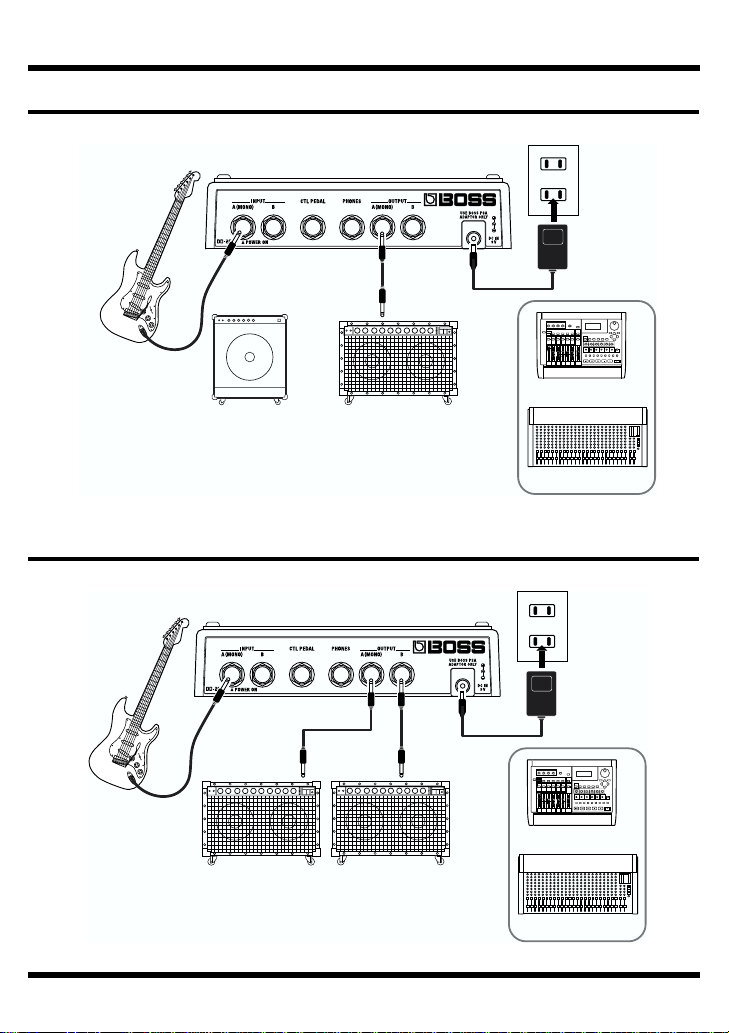
Mono Connection
fig.03
Making the Connections
AC Adaptor
PSA-series
(option)
Electric Guitar
(Electric Bass)
Stereo Connection
fig.04
Electric Guitar
(Electric Bass)
or or
Guitar AmplifierBass Amplifier
Guitar Amplifier
(Bass Amplifier)
MTR
Mixer
AC Adaptor
PSA-series
(option)
or
MTR
Mixer
Page 6
6
Making the Connections
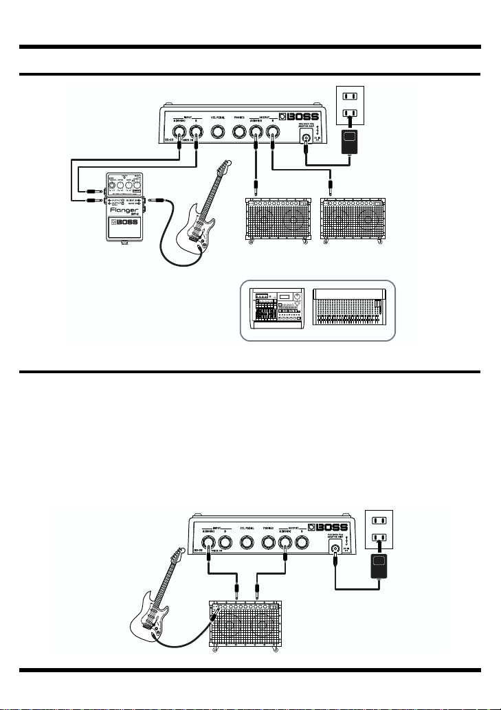
Connecting the Stereo Output and the Effects Processor
fig.05
AC Adaptor
PSA-series
(option)
Effector
Electric Guitar
(Electric Bass)
Guitar Amplifier
(Bass Amplifier)
or
MTR
Mixer
Connecting to SEND/RETURN
With Guitar and Bass Amps
* Match the DD-20's level setting and the output level from the guitar or bass amp's SEND
output. If there is any distortion in the sound, reduce the level on the connected device.
* If the guitar or bass amp's SEND/RETURN level is +4 dBu, switch the setting to “+4 dB”
as described in “Setting the Output Mode” (p. 30).
Mono Send/Mono Return
fig.06
SEND RETURN
Electric Guitar
(Electric Bass)
Guitar Amplifier
(Bass Amplifier)
AC Adaptor
PSA-series
(option)
Page 7
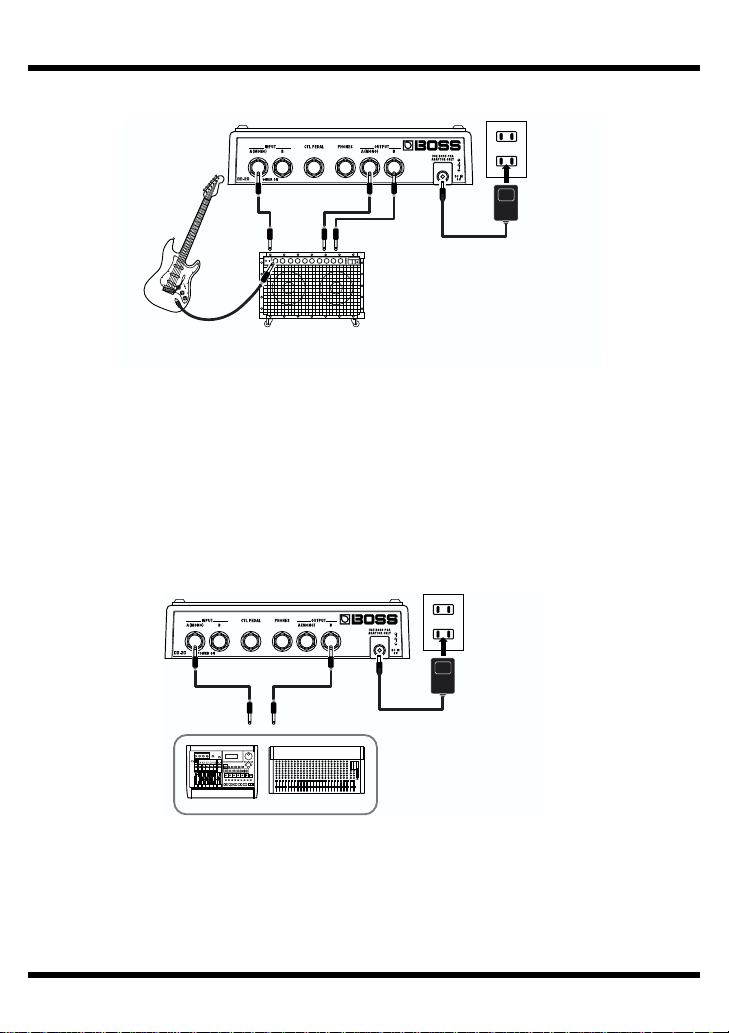
Mono Send/Stereo Return
fig.06a
SEND
7
RETURN R RETURN L
Making the Connections
AC Adaptor
PSA-series
(option)
Electric Guitar
(Electric Bass)
Guitar Amplifier
(Bass Amplifier)
Connecting to an MTR or Mixer
Mono Send/Mono Return
When using the DD-20 while connected to the SEND/RETURN of a mixer or
multitrack recorder, follow the instructions in “Setting the Output Mode” (p. 30) to
set “A: Direct Sound + B: Effect Sound” so that only the delay signal is output from
the DD-20; the sound is output from the OUTPUT B jack.
fig.07a
AC Adaptor
PSA-series
SEND RETURN
MTR
Mixer
(option)
Page 8
Operation
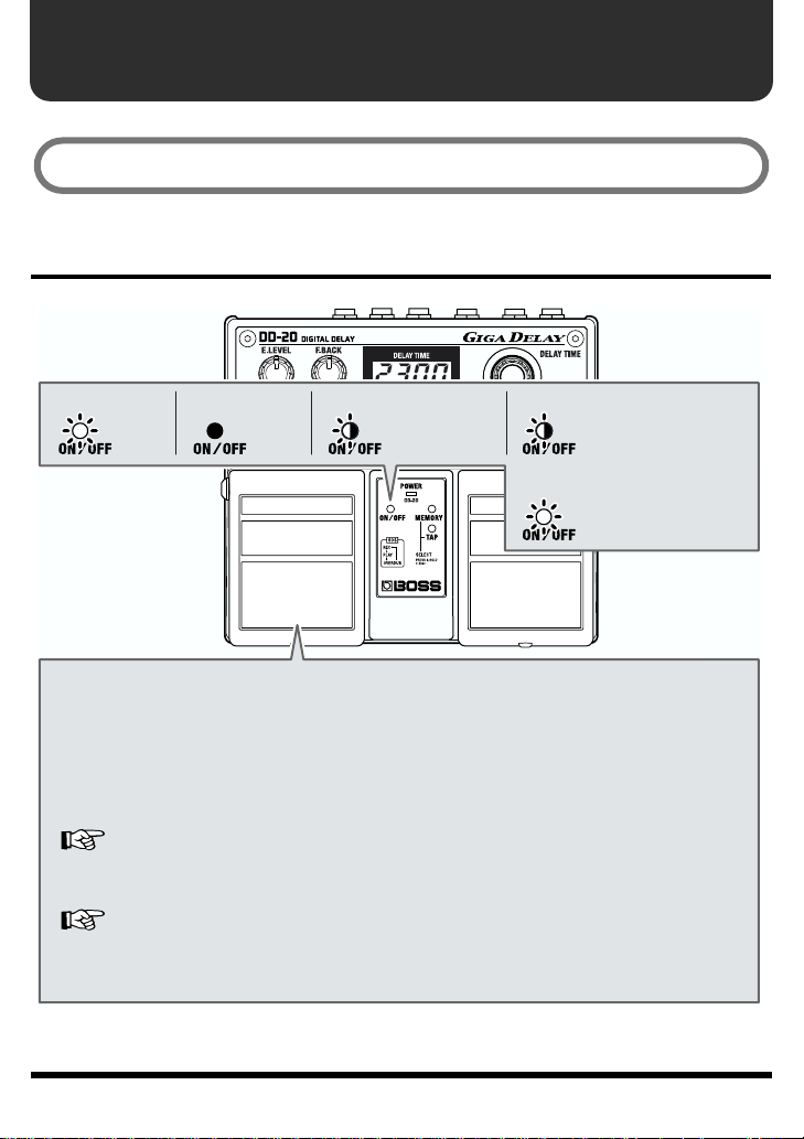
“Effect On” for the pedal setting and “MANUAL” is selected when the power is turned on.
ON/OFF Pedal Operation
fig.12
When at “ON”
← Lit
Each press of the ON/OFF pedal switches effects on or off. When effects are off, the
sound coming in through the INPUT jack is output unchanged.
* If the output is set to “A:DIR B:EFX,” nothing is output from the OUTPUT B jack
when the effects are off.
Only the effect sound is output from the OUTPUT B jack when the effects are on.
This is set at the factory to “A:DIR B:EFX.”
“
Setting the Output Mode
*
The pedal functions differently according to the Pedal mode settings.
“How to Use Each Mode” (p. 21)
* The DD-20 features a “seamless switching function” whereby the reverberation
sound decays gradually, even after the effects are switched off.
When at “OFF”
← Not lit
When at “
” (
p. 30)
WARP” or “TWIST”
← Blink
When at “SOS
← Blink
When at “SOS
← Lit
” REC or OVERDUB
” PLAY
8
Page 9
9
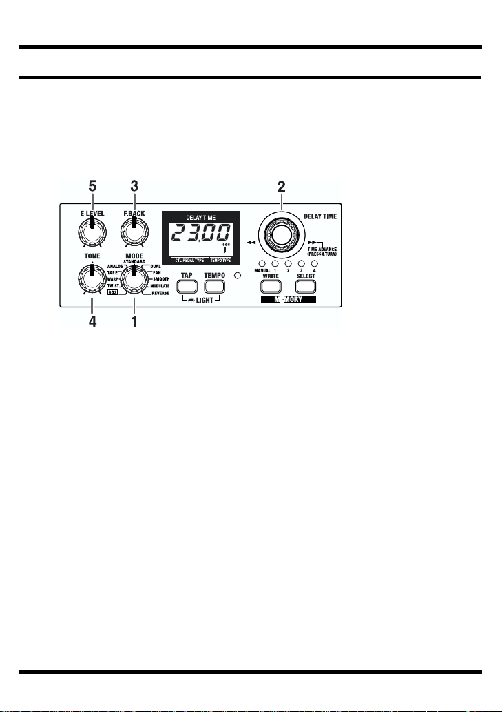
1.
2.
3.
4.
5.
Panel Operation
In order to follow along with the instructions given here, you should start out by
having effects switched ON (press the ON/OFF pedal and confirm that the ON/
OFF indicator has lighted), and press the SELECT button to switch MANUAL
(MANUAL indicator has lighted in green).
Also set the knobs as shown in the illustration.
fig.17
Rotate the MODE knob to select an appropriate delay effect from the eleven
available types.
Adjust the delay time by rotating the DELAY TIME knob.
* Pressing the knob down as you turn it cause the delay time to change more rapidly.
Furthermore, the rate at which it changes also varies according to how the knob is turned.
More detail, refer to “Operating the DELAY TIME Knob” (p. 17).
Operation
Rotate the F. BACK knob to adjust the amount of the feedback.
Adjust the tone of the effect sound with the TONE knobs.
The frequency response is flat when the knob is at the center position.
You can usually leave the knob at the center position.
Adjust the volume of the effect sound with the E.LEVEL knob.
Saving the Current Delay Time as the “Manual” Setting
If you press the DELAY TIME knob after adjusting the delay time, the current
delay time is then stored to the DD-20 as the “Manual” setting.
This setting is preserved even while the power is turned off, and is selected as
the default delay time setting (display) when the power is turned on again.
Page 10
Operation
Storing Settings (Write Operation)
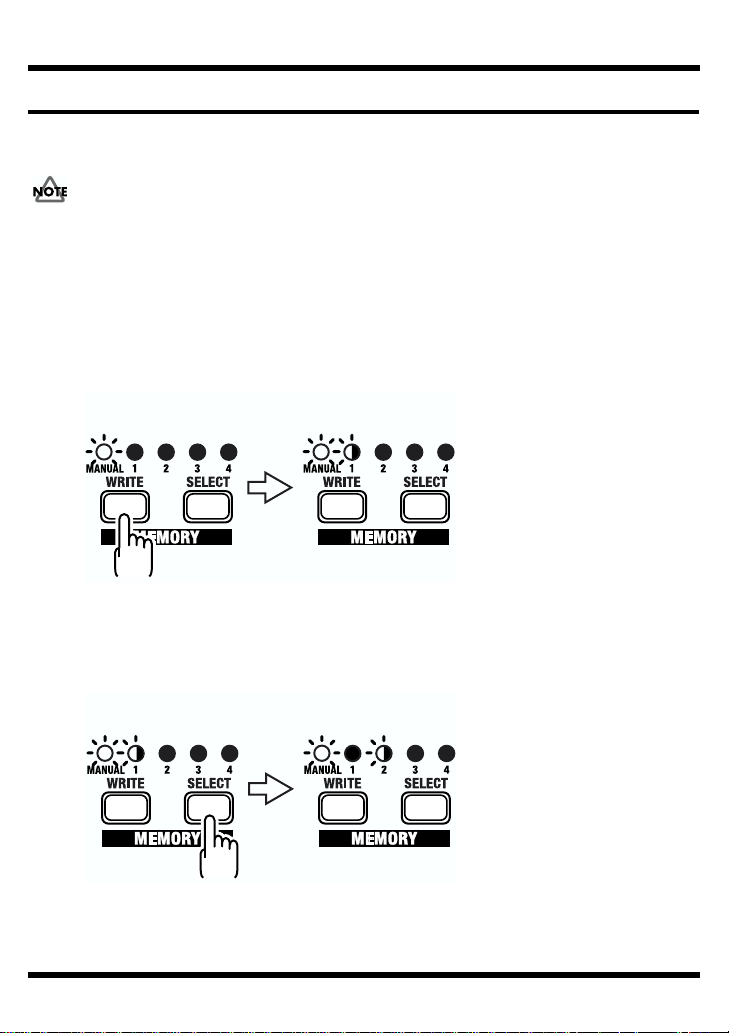
Storing the “MANUAL” Sound in Memory
Do not switch off the power while a write operation is in progress.
* You cannot carry out the Write operation when the MODE knob is turned to “SOS.”
Create the sound you want using knobs.
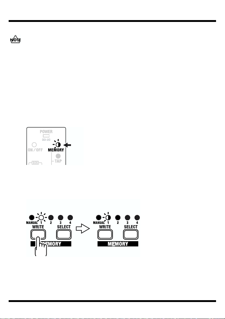
Press the WRITE button.
The MEMORY indicator and the indicator for the currently selected memory flash,
and the DD-20 is put into write standby.
fig.19a
Write standby
Blink
10
1.
2.
3.
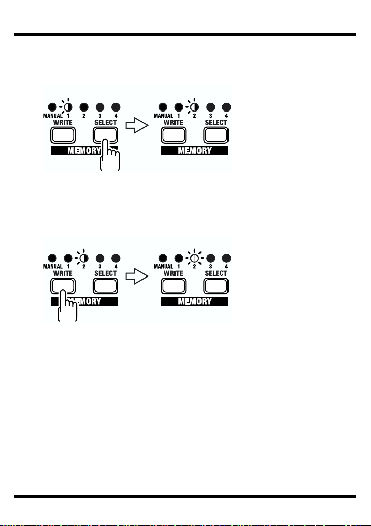
Press the SELECT button to select the memory (number) to which you want
to store the sound.
The indicator for the selected memory number flashes.
fig.19b
Write standby
BlinkBlink
Page 11
Operation
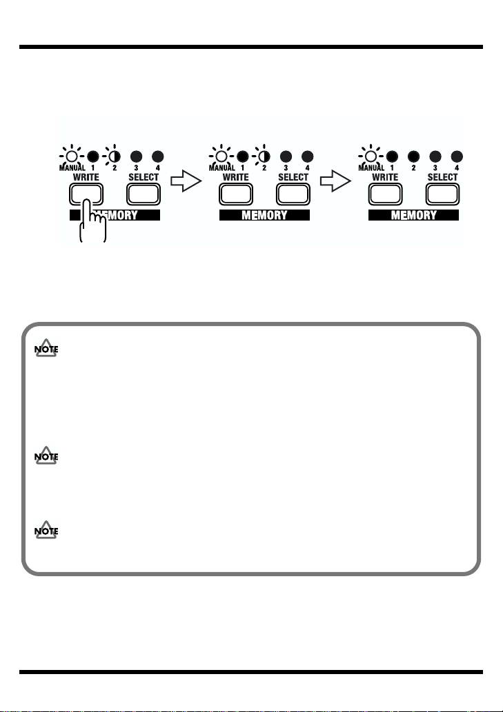
Press the WRITE button.
The write operation is completed when the indicator for the write-destination
memory begin to flash more rapidly.
fig.20
Writing
Write Finished
Blink Blink rapidly
* To cancel the write operation, then before you press the WRITE button, rotate the knob or
operate the MANUAL/TAP pedal.
Please be aware that all data contained in the unit’s memory may be lost when the
unit is sent for repairs. Important data should always be written down on paper,
“Setting Memo” (p. 40). During repairs, due care is taken to avoid the loss of data.
However, in certain cases (such as when circuitry related to memory itself is out of
order), we regret that it may not be possible to restore the data, and Roland assumes
no liability concerning such loss of data.
11
4.
Please be aware that the contents of memory can be irretrievably lost as a result of a
malfunction, or the improper operation of the unit. To protect yourself against the risk
of loosing important data, we recommend that you write down important data you
have stored in the unit’s memory on “Setting Memo” (p. 40).
Unfortunately, it may be impossible to restore the contents of data that was stored in
the unit’s memory once it has been lost. Roland Corporation assumes no liability
concerning such loss of data.
Page 12
Operation
Changing and Storing the “MEMORY” Sound
Do not switch off the power while a write operation is in progress.
Press the MANUAL/TAP pedal or the SELECT button to change to the
“MEMORY” sound.
2. Operate the knobs to change the sound.
* To avoid sudden inadvertent changes in sound, the E.LEVEL, TONE, and F. BACK knobs
are designed so that the setting does not change unless the knob is first turned as far as the
stored setting value. Once the position of the knob matches the setting value stored in
memory, the sound starts to change.
When a setting changes, the MEMORY indicator flashes automatically.
fig.21
Blink
3. Press the WRITE button.
The MEMORY indicator and the indicator for the currently selected memory
number start to flash, and the DD-20 is put into write standby.
fig.22
Write standby
Blink
12
1.
Page 13
Operation
4. Press the SELECT button to select the memory (number) to which you want
to store the sound.
The indicator for the selected memory number flashes.
fig.22a
BlinkBlink
5. Press the WRITE button.
The write operation is completed when the indicator for the write-destination
memory begin to flash more rapidly.
fig.23
Blink rapidly Lit
* If the knob or the MANUAL/TAP pedal position is changed before the WRITE button is
pressed, the write operation is cancelled, and the DD-20 is returned to the status in effect in
Step 2.
13
Page 14
Operation
MEMORY/TAP Pedal Operation (Switching Memories)
The Pedal mode (1–3) changes the function of the pedals. Use the most appropriate
setting for your particular application.
* The following operations are performed while the MEMORY indicator is lit.
* The DD-20 features a “seamless switching function.”
When you switch memories using this function, the reverberation from the memory prior to
switching continues to sound, for more natural-sounding transitions.
* At the factory settings, Pedal mode is set to “1.”
When changing the Pedal mode settings, refer to p. “Changing the Pedal Mode Settings”
(p. 29).
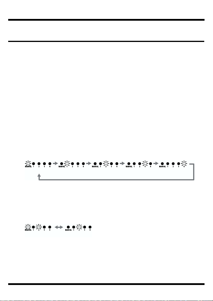
Pedal mode: 1
Pressing the MEMORY/TAP pedal cycles you through a series of selections, in this
order: MANUAL → MEMORY 1 → MEMORY 2 → MEMORY 3 → MEMORY 4 →
MANUAL. This convenient feature makes it easier to switch memories in which
multiple memories are used.
fig.9
MANUAL MEMORY 1 MEMORY 2 MEMORY 3 MEMORY 4
Pedal mode: 2
Pressing the MEMORY/TAP pedal switches you between MANUAL and the
selected memory (shown by the lit indicator). This is a convenient way to toggle
between two sound settings.
fig.10
MANUAL MEMORY
14
Page 15

Operation
Pedal mode: 3
Pressing the MEMORY/TAP pedal toggles you between MANUAL and the
selected memory (shown by the lit indicator).
fig.11
MANUAL MEMORY
You can also select among Memories 1–4 by pressing the MEMORY/TAP pedal and
ON/OFF pedal simultaneously. This is convenient when you want to use your foot to
rapidly switch memories to call up a desired sound.
* You cannot carry out this operation when the MODE knob is turned to “SOS.”
fig.12
MEMORY 1 MEMORY 2 MEMORY 3 MEMORY 4
MEMORY/TAP Pedal Operation (Tap Input)
When the MODE knob is turned to any setting besides “SOS,” then pressing and
holding down the pedal for at least two seconds causes the TAP indicator to light
up and switches the MEMORY/TAP pedal function to Tap Input.
fig.12-1
Lit
Lit
You can easily set the delay time to match the tempo of the song being played by
pressing the pedal in time with the song’s tempo (Tap Input).
The TEMPO indicator flashes in time with the tempo being input with Tap Input.
* You can use the TEMPO button to change the delay time set with Tap Input. Refer to
“How to Use the Tempo Function” (p. 26).
15
Page 16

Part Names and Functions
Front Panel
fig.24
F.BACK (feedback) Knob
Adjusts the feedback level (or how much
the sound is repeated).
* Oscillation may occur with certain input
sounds, or when the knob is set at
certain positions.
* This knob is not functional when “SOS”
is selected as the mode (p. 18).
E.LEVEL (effect level) Knob
Adjusts the volume of the effect
sound.
TONE Knob
This adjusts the tone of
the effect's sound.
The frequency
response is flat when
the knob is set to the
center position; turning
it to the right boosts the
higher frequencies,
and turning it to the left
cuts the higher
frequencies.
This knob is not
*
functional when
“SOS” is selected
as the mode (p. 18).
MODE Knob
Select the type of
delay effect (p. 18).
DELAY TIME Knob
This sets the delay time for the sound.
You can turn the knob without pushing it (changing the
delay time in 1-msec units) or while pushing it (activating
the Time Advance function).
“Operating the DELAY TIME Knob” (p. 17)
MEMORY Number
Indicators (1–4)
The indicator for the currently selected
MEMORY number (1–4) lights.
The indicator flashes while the
DD-20 is in write standby; the
indicator flashes more rapidly while
the write operation is in progress.
SELECT Button
This changes
MANUAL or
memories 1–4.
WRITE Button
Press this to store
settings in
“MEMORY.”
TAP Button
The delay time is set
according to the intervals
between taps of the button.
You can switch between the
delay time indicator and the BPM
indicator by holding down the
button for two seconds or longer.
16
TEMPO Button
This is used to specify the length of the
delay time for the tempo input with Tap
Input in terms of the note length.
* You can turn the display backlighting on
and off by together pressing both the
TAP button and the TEMPO button.
TEMPO Indicator
This flashes in time with
the beat for the selected
tempo.
Page 17

Part Names and Functions
Operating the DELAY TIME Knob
When adjusting the delay time with the DELAY TIME knob, the setting normally
changes in units of one millisecond (or ten milliseconds if the time is ten seconds or
longer). However, simultaneously pressing and turning the knob causes the delay
time setting to change rapidly, allowing you to quickly reach the value you want,
even with higher values. This feature is called the “Time Advance function.”
The settings range for Delay Time is from one millisecond to 23 seconds. When the
BPM is indicated (p. 27), the settings range is from 3 to 9999.
* The range of the setting varies according to the mode and tempo selected.
Normal Operation
• Turning this knob to the right increases the delay time in units of one millisecond
(one click).
• Turning this knob to the left decreases the delay time in units of one millisecond
(one click).
Operating the Time Advance Function
fig.27
Knob first pressed here
Unit of change gradually
increases up to -10 clicks
Unit of change gradually
increases up to +10 clicks
• When you hold down the knob and turn it to the right, the delay time starts
increasing. The rate of change increases the more the knob is turned.
• When you hold down the knob and turn it to the left, the delay time starts
decreasing. The rate of change increases the more the knob is turned.
17
Page 18

Part Names and Functions
MODE List
In this mode, you can record up to 23 seconds of material and repeat-
SOS
(Sound On Sound)
TWIST
WARP
TAPE
ANALOG This tone is modeled on the BOSS “DM-2” Compact Delay.
STANDARD This is normal delay.
DUAL
PAN
SMOOTH
MODULATE
REVERSE
* You can choose how the sound is output from the OUTPUT jacks in “Setting the Output
Mode” (p. 30); select either “STEREO OUTPUT” or “A: Direct Sound, B: Effect Sound.”
edly play back the phrases from the material. What's more, you can
record new phrases and add them to the previous material (overdub)
as many times as you like.
→ “How to Use SOS (Sound On Sound)” (p. 21)
This is a new type of delay that produces an aggressive, spinning sensation. Using this with distortion creates an even wilder twist.
→ “How to Use TWIST” (p. 22)
This simultaneously controls the delay sound's feedback level and volume to produce a totally unreal delay.
→ “How to Use WARP” (p. 22)
This tone is modeled on the Roland “RE-201” Tape Echo. You can adjust the settings to change the number of “heads.”
* The delay time can be set in a range from 120 milliseconds to 23 seconds.
→ “How to Use TAPE” (p. 23)
This is a delay with short and long delays connected in series.
→ “How to Use DUAL” (p. 24)
This is a panning delay, with the delay sound output alternately from
the left and right sides (OUTPUT A/B).
This delay spreads out spatially, producing a more natural reverberation effect.
This delay adds a pleasant wavering effect to the sound.
→ “How to Use MODULATE” (p. 25)
This creates a reverse playback effect. You can adjust the E.LEVEL
knob setting to get two different kinds of effect, “Direct Sound + Effect
Sound” and “Effect Sound Only.”
Turning the E.LEVEL knob completely to the right switches this to “Effect Sound Only.”
* The delay time can be set in a range from 10 milliseconds to 23 seconds.
18
Page 19

fig.25
Part Names and Functions
DUAL Indicator
(SHORT, LONG)
Indicates the delay time as well
as the delay (SHORT, LONG)
when the DD-20 is set to DUAL
mode.
Output Mode Indicator
(A:EFX, B:DIR, +4dB)
“Setting the Output
Mode” (p. 30)
Control Pedal Function
Indicator
(
ON/OFF, TAP, MEM)
“Setting the External Pedal
Function” (p
. 31)
ON/OFF
Indicator
This lights up when
effects are on.
Display
When the power is turned on, the backlighting comes on, then
goes off again after approximately twenty seconds. This feature is
intended to prevent unnecessary battery drainage. If you want to
keep the backlighting on, simultaneously press the TAP button and
TEMPO button; the light then stays on.
* Remember to check on battery power consumption.
* Never strike or apply strong pressure to the display.
DELAY TIME
This shows the unit of time for the
currently selected delay time (or
BPM unit).
When MODE is set to SOS, it indicates
the remaining memory (%) during
recording and the loop phrase position
during playback and overdubbing.
Tempo Type Indicator
( )
3 3
“How to Use the Tempo
Function” (p
. 26)
POWER
Indicator
This lights up when
the power is on.
ON/OFF Pedal
Each press of the
pedal switches the
effects on or off.
With MODE set to
WARP or TWIST,
pressing on the pedal
produces the
corresponding effect.
MEMORY Indicator
This is lit when the
MEMORY/TAP pedal is used
for switching between
MANUAL and memories (1–4).
TAP Indicator
This is lit when the
MEMORY/TAP pedal is used
for Tap Input.
MEMORY/TAP Pedal
This pedal performs two functions, as a
“Memory Pedal” used for switching
between MANUAL and memories (1–4),
and for “Tap Input” of the delay time.
“MEMORY/TAP Pedal Operation”
(p. 14, 15)
19
Page 20

Part Names and Functions
Rear Panel
fig.26
INPUT Jacks (A (MONO), B)
This is the input jack for connecting to the
output of an electric guitar or other
instrument or effects processor.
For MONO use, make the connection to the
A (MONO) jack.
“Making the Connections” (p. 4)
* The INPUT A (MONO) jack also doubles
as the power switch when the unit is
running on battery power. The power
comes on when a plug is inserted into the
INPUT A (MONO) jack, and goes off when
it is unplugged. Unplug any connected
cords when the unit is not in use.
PHONES Jack
You can connect headphones here to monitor the
sound.
*Turn on the power before you connect
headphones. When turning off the power, first
unplug the headphones, then switch off the power.
* Please observe due caution when using
headphones while the Output Mode is set to +4 dB,
since their volume may get significantly higher.
AC Adaptor Jack
This jack is for connecting an AC adaptor
(BOSS PSA-series, sold separately).
Using an AC adaptor makes possible
long performances with no worry about
batteries going dead.
CTL PEDAL Jack
Connect an external control pedal (the optional BOSS
FS-5L/FS-5U) to this jack.
You can use the external control pedal to turn the
effect on and off, to input the delay time with Tap
Input, and to switch memories.
“Setting the External Pedal Function” (p. 31)
20
OUTPUT Jacks (A (MONO), B)
This jack is for connection to a
guitar/bass amp, another effects
processor, mixer, MTR, or the like.
For MONO use, make the connection to
the A (MONO) jack.
“Making the Connections (p. 4)
Page 21

How to Use Each Mode
How to Use SOS (Sound On Sound)
1. Turn the MODE knob to “SOS.”
2. Press the ON/OFF pedal to start recording.
Play what is to be used as the basic phrase.
The remaining memory is indicated as a percentage in the display.
fig.29
Blink
3. Press the ON/OFF pedal again to stop recording.
Loop playback of the recorded phrase begins at the same time you press the pedal.
The loop time is indicated in the display as shown below.
The TEMPO indicator also flashes.
fig.30
4. Overdub another phrase.
Sounds are overdubbed during loop playback only while the pedal is held down.
Continue to hold the pedal down as you play the phrase you want to record.
* If the ON/OFF pedal is held down only for a brief period, loop playback stops, and the
recorded phrase is erased.
By pressing the MEMORY/TAP pedal during loop playback, you can have the
delay applied to the guitar sound as loop playback continues. However, you cannot
overdub. To stop loop playback, press the MEMORY/TAP button again (we
recommend Pedal Mode 2 or 3).
21
Page 22

How to Use Each Mode
How to Use TWIST
1. Turn the MODE knob to “TWIST.”
2. Hold down the ON/OFF pedal.
The delay sound starts to oscillate, then the oscillation speeds up as its pitch
increases.
fig.32
Blink
3. Release the pedal.
The oscillating sound begins to fade away, and the normal delay sound returns.
This effect works very well with distortion sounds, and combining it with
distortion results in an even wilder effect (you can adjust the volume of the
oscillating sound with the E.LEVEL knob). Using this for the ending of a song is
effective.
* You can switch the normal effect on and off by pressing the ON/OFF pedal only briefly.
How to Use WARP
1. Turn the MODE knob to “WARP.”
2. Hold down the ON/OFF pedal.
The feedback level and volume increase.
fig.32
Blink
3. Release the pedal.
The effect corresponding to the knob positions (E.LEVEL, F.BACK) resumes.
You can create fantastic effects by repeating the “warped” delay sound and then
playing a phrase on top of this.
* You can switch the normal effect on and off by pressing the ON/OFF pedal only briefly.
22
Page 23

How to Use Each Mode
How to Use TAPE
You can have either one or two “playback heads” used for the tape echo effect.
Setting this to “2” produces a multi-tap delay effect.
1. Turn the MODE knob to “TAPE.”
2. Hold down the ON/OFF pedal until “HEd1” or “HEd2” appears in the display.
3. You can change the number of playback heads used by continuing to hold
down the ON/OFF pedal as you turn the DELAY TIME knob.
HEd1: One head is used
HEd2: Two heads are used
fig.35
* This is set at the factory to “HEd1.”
* This setting is preserved even after the power is turned off. If you want to save it as a
setting for the Memories (1–4), then carry out the Write procedure (p. 10).
23
Page 24

How to Use Each Mode
How to Use DUAL
Although DUAL mode features a short delay and long delay connected in series,
you can change the delay time for the short delay.
1. Turn the MODE knob to “DUAL.”
2. Hold down the ON/OFF pedal until “SHORT” appears in the display.
In this case, the short delay’s delay time is indicated.
fig.36
3. You can change the delay time by continuing to hold down the ON/OFF pedal
as you turn the DELAY TIME knob.
* This is set at the factory to “SHORT 50msec, LONG 300 msec.”
* This setting is preserved even after the power is turned off. If you want to save it as a
setting for the Memories (1–4), then carry out the Write procedure (p. 10).
24
Page 25

How to Use Each Mode
How to Use MODULATE
You can change the MODULATE modulation rate and depth settings.
1. Turn the MODE knob to “MODULATE.”
2. Hold down the ON/OFF pedal until “r” appears in the display.
The rate value appears next to the “r” in the display.
fig.37
3. You can change the rate value by continuing to hold down the ON/OFF pedal
as you turn the DELAY TIME knob.
4. Hold down the ON/OFF pedal and turn the DELAY TIME knob to have “d”
displayed.
The depth value appears next to the “d” in the display.
* Press the DELAY TIME knob once more to have “r” displayed.
fig.37
Press
5. You can change the depth by continuing to hold down the ON/OFF pedal as
you turn the DELAY TIME knob.
* This is set at the factory to “r:80, d:70.”
* This setting is preserved even after the power is turned off. If you want to save it as a
setting for the Memories (1–4), then carry out the Write procedure (p. 10).
25
Page 26

How to Use the Tempo Function
The DD-20 includes a “Tempo function,” which allows you to specify the delay
time in terms of note lengths.
The display is switched as shown below each time you press the TEMPO button.
fig.39
(Quarter
note)
(Dotted 8th note) (Quarter note
triplet)
(8th note) (8th note
Blink
(Half note
triplet)
(Dotted
quarter note)
(Half note)
* Notes for certain delay time settings may not be indicated in the display.
* The range of the delay time setting differs according to the tempo selected.
The delay sound produced is as shown in the figure.
fig.40
Rhythm Used in
Pressing the TAP Pedal
or the TAP Button
(Dotted
half note)
triplet)
(Whole note)
* If you want to set the delay time to match the timing of the tap input, select “Quarter Note.”
26
Page 27

Indicating the BPM in the Delay Time Display
You can switch the DD-20’s time delay display to show the tempo (BPM).
If, for example, you already know the BPM of the song you are performing, you
can get a perfectly synchronized delay effect by setting the delay time with the
indicated tempo (BPM).
* Specifying the note lengths with the TEMPO button also makes it easy to specify the times
for dotted notes, triplets, and other kinds of notes.
1. Hold down the TAP button until the delay time indicated in the display
changes to show the tempo (BPM).
fig.41
Use this same procedure to return to the time (msec) display.
When the delay time is saved after switching the display, the method used to
display it is also saved.
27
Page 28

Settings Made When the Power is Switched ON
You can make the following settings with the operations performed while turning
on the power.
fig.42
WRITE Button
Returns settings to their factory defaults.
“Returning Settings to Their
Factory Defaults” (p. 34)
SELECT Button
This sets the pedal mode.
“Changing the Pedal Mode
Settings” (p. 29)
WRITE Button +
SELECT Button
Set how the Memory
numbers are to be
indicated.
“Setting the External
Pedal Function”
(p. 33)
ON/OFF Pedal
This sets the output mode.
“Setting the Output Mode” (p
. 30)
MEMORY/TAP Pedal
This sets the External Pedal Function.
“Setting the External Pedal
Function” (p. 31)
Global Procedures
Switch off the power.
• When running on battery power:
Disconnect the connection plug from the INPUT A (MONO) jack.
• When running on power from an AC adaptor:
Disconnect the plug from the INPUT A (MONO) jack and the AC ADAPTOR jack.
Switch on the power.
• When running on battery power:
Insert the connection plug into the INPUT A (MONO) jack.
• When running on power from an AC adaptor:
Insert the AC ADAPTOR plug into the AC ADAPTOR jack.
28
Page 29

Settings Made When the Power is Switched ON
Changing the Pedal Mode Settings
Use the following to change the Pedal mode settings.
* Pedal mode settings are saved even after the power is turned off.
1. Switch off the power.
2. While holding down the SELECT button, switch on the power.
The MEMORY 1–3 indicator corresponding to the current Pedal mode settings flashes.
The Pedal mode is indicated in the display.
3. Set the pedal mode (1-3) pressing the SELECT button.
fig.43
Pedal Mode 1 Pedal Mode 2 Pedal Mode 3
4. Press the WRITE button.
After the MEMORY Number indicator begins flashing rapidly, the setting is stored
in memory and the unit returns to its ordinary state.
* To cancel the setting change and return the unit to its ordinary state, then before you press
the WRITE button, operate the MEMORY/TAP or ON/OFF pedal.
Pedal
Mode
* Only Pedal mode 3 is enabled when the MEMORY/TAP pedal is being used as a Tap Input
pedal (when the TAP indicator is lit).
* This is set at the factory to Pedal Mode 1.
ON/OFF Pedal MEMORY/TAP Pedal
1 Effect on/off
2 Effect on/off
3 Effect on/off
Switches MANUAL or
MEMORY 1–4
Switches MANUAL or
MEMORY
Switches MANUAL or
MEMORY
ON/OFF Pedal
MEMORY/TAP Pedal
-
-
Selects from MEMORY
1–4
+
29
Page 30

Settings Made When the Power is Switched ON
Setting the Output Mode
When using the DD-20 while connected to a guitar or bass amp, mixer, or
multitrack recorder SEND/RETURN, you can set the output level (+4 dB) and
method of output from the OUTPUT jacks (A: Direct Sound/B: Effect Sound) to
match the device connected to the DD-20.
1. Switch off the power.
2. While holding down the ON/OFF pedal, switch on the power.
The output mode setting is indicated in the display, and the MEMORY 1–4
indicator corresponding to the current setting flashes.
3. Set the output mode pressing the SELECT button.
fig.44
Output Mode 1 Output Mode 2 Output Mode 3 Output Mode 4
4. Press the WRITE button.
After the MEMORY Number indicator begins flashing rapidly, the setting is stored
in memory and the unit returns to its ordinary state.
* To cancel the setting change and return the unit to its ordinary state, then before you press
the WRITE button, operate the MEMORY/TAP or ON/OFF pedal.
Display Mode Output Level
out1 1 Stereo output -20 dB
out2,
A:DIR / B:EFX
out3, +4dB 3 Stereo output +4 dB
out4,
A:DIR / B:EFX, +4dB
* Even when this is set to “A: Direct Sound/B: Effect Sound,” if the input is in stereo, then
the output will also be in stereo. Additionally, if the input is mono while nothing is
connected to the OUTPUT B jack (effect sound), then the sounds are not output as “A:
Direct Sound/B: Effect Sound.” If you want to have the output be “A: Direct Sound/B:
Effect Sound,” then set the DD-20 so that “A:DIR, B:EFX” appears in the display.
* This is set at the factory to “Output Mode 1.”
2
4
A: Direct Sound/B: Effect
Sound
A: Direct Sound/B: Effect
Sound
-20 dB
+4 dB
30
Page 31

Settings Made When the Power is Switched ON
Setting the External Pedal Function
You can connect an optional foot switch (the FS-5U or FS-5L) to the CTL PEDAL
jack and use the pedal for turning the effects on and off, for tap input, and for
switching memories.
fig.45 Polarity switch
Connection cord
(1/4 inch phone type)
Set the polarity switch as
shown in the following figure.
or
1. Switch off the power.
2. While holding down the MEMORY/TAP pedal, switch on the power.
The setting is indicated in the display, and the MEMORY 1–3 indicator
corresponding to the current setting flashes.
3. Set the external pedal function pressing the SELECT button.
Each time you press the SELECT button, it switches through the “ON/OFF,” and
“TAP,” “MEM.”
fig.46
CTL 1 CTL 2 CTL 3
31
Page 32

Settings Made When the Power is Switched ON
4. Press the WRITE button.
After the MEMORY Number indicator begins flashing rapidly, the setting is stored
in memory and the unit returns to its ordinary state.
* To cancel the setting change and return the unit to its ordinary state, then before you press
the WRITE button, operate the MEMORY/TAP or ON/OFF pedal.
Display Mode Function Foot Switch
ctl1, ON/OFF CTL1
ctl2, TAP CTL2 Tap input FS-5U (Momentary Type)
ctl3, MEM CTL3 Switches Memories FS-5U (Momentary Type)
* This is set at the factory to “CTL 2.”
* When you connect an external pedal after making this setting, the function you have set
appears in the display, indicating that the function can be used.
• When the CTL1 mode is selected and you are using the DD-20 in conjunction
with an OD-20, you can turn the DD-20 on and off with the OD-20’s AMP CTRL
button by connecting the DD-20’s CTL PEDAL jack and the OD-20’s AMP CTRL
jack.
• When using an external pedal to turn the effect on and off with the DD-20 set to
CTL1 mode, if you try to switch the effect on or off with the DD-20’s ON/OFF
pedal, the external pedal’s actual function will differ from the function that is
indicated.
• The following parameters cannot be controlled by the external pedal when the
external pedal is being used to turn the effect on and off with the DD-20 set to
CTL1 mode.
• Recording, playback, and overdubbing in Sound On Sound (p. 21)
• TWIST (p. 22)
• WARP (p. 22)
• TAPE playback head setting (p. 23)
• DUAL short delay time setting (p. 24)
• MODULATE modulation rate setting (p. 25)
Switches effects on
and off
FS-5L (Latch Type)
32
Page 33

Settings Made When the Power is Switched ON
Changing How Memory Numbers Are Indicated
Not only can you confirm the currently selected memory merely by checking the lit
MEMORY number indicators, you can also change the pattern in which the
indicators light up. Select the pattern that provides the easiest way to check the
memory in any particular environment.
When using the DD-20 in dimly lit surroundings, you can confirm memory
numbers more easily by using the Lighting Pattern 2 setting.
Lighting Pattern 1 (Normal):
Only the indicator for the selected memory lights up (or flashes).
fig.47
MANUAL
MANUAL
MANUAL
MEMORY 1
Lighting Pattern 2:
The number of indicators lighting up (or flashing) corresponds to the selected
memory number.
fig.48
MANUAL
MANUAL
MANUAL
MEMORY 1
1. Switch off the power.
2. While holding down the WRITE button and the SELECT button, switch on the power.
3. Press the SELECT button to set the MEMORY indicator lighting pattern.
fig.49
MANUAL
MANUAL
MEMORY 2
MEMORY 2
MANUAL
MANUAL
MEMORY 3
MEMORY 3
MANUAL
MANUAL
MEMORY 4
MEMORY 4
Lighting Pattern 1 Lighting Pattern 2
4. Press the WRITE button.
After the MEMORY Number indicator begins flashing rapidly, the setting is stored
in memory and the unit returns to its ordinary state.
* To cancel the setting change and the unit returns to its ordinary state, then before you
press the WRITE button, operate the MANUAL/TAP or ON/OFF pedal.
33
Page 34

Settings Made When the Power is Switched ON
Returning Settings to Their Factory Defaults
You can restore the following settings to their original factory values.
Memory 1 (p. 12) SMOOTH
Memory Settings
MANUAL Delay Time (p. 9)
(when the power is switched on)
DUAL Short Delay Time (p. 24) S: 50
MODULATE Rate/Depth (p. 25) r: 80, d: 70
TAPE (p. 23) HEd1
Pedal Mode (p. 29) Mode 1
Output Mode (p. 30) Mode 1
External Pedal Function (p. 31) TAP
MEMORY Number Indication (p. 33) Lighting Pattern 1
Carrying out the following procedure completely clears the content currently
stored in the memories (1-4).
1. Switch off the power.
2. While holding down the WRITE button, switch on the power.
The MEMORY Number indicators (1-4) flash.
fig.50
Memory 2 (p. 12) TAPE
Memory 3 (p. 12) DUAL
Memory 4 (p. 12) MODULATE
MANUAL: 300 msec
3. Press the WRITE button.
After the MEMORY Number indicators (1-4) begin flashing rapidly, the setting is
stored in memory and the unit returns to its ordinary state.
* To cancel the setting change and the unit returns to its ordinary state, then before you
press the WRITE button, operate the MEMORY/TAP or ON/OFF pedal.
34
Page 35

Troubleshooting
The power doesn’t come on.
❍ Is the guitar connected correctly to the INPUT
A (MONO) jack?
→ Check the connections again (p. 4–p. 7).
* When running off batteries, the unit won’t switch
on unless there’s something plugged into the
INPUT jack. This helps conserve the batteries.
Is the plug connected to the INPUT B jack?
❍
→ When using battery power, connect the plug to
the INPUT A (MONO) jack.
❍ Have the batteries run down?
→ Replace with fresh batteries (p. 3).
❍ Is the specified AC adaptor (PSA-series sold
separately) connected correctly?
→ Check the connections again (p. 4–p. 7).
There is no sound.
❍
Is the other equipment connected correctly?
→ Check the connections again (p. 4–p. 7).
❍ Is the volume turned down on the connected
guitar/bass amp, effects processor, or other
device?
→ Check the settings on the connected equipment
(p. 4–p. 7).
❍ Is the Output Mode set correctly?
→ Set the Output Mode to match the connected
equipment (p. 30).
❍ Is the Output Mode set to A: DIR / B: EFX?
→ No sound is output from the OUTPUT B jack
when the ON/ OFF pedal is set to OFF. Set the
Output Mode to Stereo output (out 1 or out 3)
(p. 30).
❍ Is the effect level (E. LEVEL knob) set to minimum?
→ Operate the E.LEVEL knob to adjust the effect
level (p. 16).
Sound is distorted.
❍ Are the TONE knob positioned correctly?
→ Sounds may become distorted with the knob at
certain settings. Turn down this knob, or turn
down the E.LEVEL knob to appropriate level. If
in spite of these measures the sound is still
distorted, lower the output level of the device
connected to the INPUT jacks, or set the Output
Mode to +4 dB (p. 30).
Pressing the MEMORY/TAP pedal
does not call up the intended
memory.
❍ Is the proper Pedal mode set for your current
application?
→ The MEMORY/TAP pedal (or the MEMORY/
TAP pedal when pressed simultaneously with
ON/OFF pedal) functions differently according
to the Pedal mode settings. Use the most
appropriate setting for your particular
application (p. 29).
❍ Is the MEMORY/TAP pedal set to the TAP
function?
→ If the MEMORY/TAP pedal is set to TAP
(MEMORY/TAP pedal has been pressed for
two seconds), the pedal functions as a Tap
Input pedal. To switch memories, either change
the pedal to the MEMORY switching function
by holding down the MEMORY/TAP pedal for
two seconds, or use an external pedal
(p. 14–p. 15).
The volume level of the
instrument connected to INPUT
jack is too low.
❍ Could you be using a connection cable that
contains a resistor?
→ Use a connection cable that does not contain a
resistor.
35
Page 36

Troubleshooting
Pressing the ON/OFF pedal does
not switch on or off as intended.
❍ Is the Pedal mode set to SOS, WARP or
TWIST?
→ The pedal functions differently according to the
Pedal mode settings. For more details, refer to
the description of each mode.
SOS (p. 21), WARP (p. 22), TWIST (p. 22)
Cannot be saved to the memories
❍ The delay time cannot be saved in SOS or
MANUAL.
→ SOS cannot be saved to the memories.
Delay time settings in MANUAL are saved by
pressing the DELAY TIME knob or switching
memories before the power is turned off.
Information not displayed
❍ External pedal not indicated.
→ The external pedal is not indicated unless it is
connected (p. 31).
❍ Output mode not indicated.
→ A: DIR/B: EFX is not indicated when input is in
stereo.
For more detailed information, refer to “Setting
the Output Mode” (p. 30).
❍ The set delay time is different than the time
displayed.
→ Manual delay time settings change unless the
Write procedure is carried out. The settings are
saved when you press the DELAY TIME knob
or switch memories.
❍ The delay time does not reach the maximum
of 23 seconds
→ The range of the delay time setting may vary
according to the mode and the tempo setting.
For more detailed information, refer to “MODE
List” (p. 18) and “How to Use the Tempo
Function” (p. 26).
36
Page 37

Sample Settings
SMOOTH (Memory 1)
fig.36
Roland SPACE ECHO RE-201 (Memory 2)
fig.36
MODE: TAPE HEd2
DUAL (Memory 3)
fig.36
MODE: DUAL/SHORT 50 msec
37
Page 38

Sample Settings
MODULATE (Memory 4)
fig.36
MODE: MODULATE/RATE 80, DEPTH 70
TWIST
fig.36
Holding down the ON/OFF pedal produces the twist effect.
REVERSE
fig.36
38
Page 39

ROOM AMBIENCE
fig.36
SLAP BACK ECHO
fig.36
MODULATE DOUBLING
fig.36
Sample Settings
MODE: MODULATE/RATE 25, DEPTH 95
39
Page 40

Setting Memo
( )
fig.36
( )
fig.36
40
( )
fig.36
Page 41

Specifications
DD-20: DIGITAL DELAY
Nominal Input Level
-20 dBu (GUITAR/BASS)
+4 dBu (AMPLIFIER SEND/RETURN)
Input Impedance
1 MΩ
Nominal Output Level
-20 dBu (GUITAR/BASS)
+4 dBu (AMPLIFIER SEND/RETURN)
Output Impedance
1 kΩ (OUTPUT A (MONO), B)
33 Ω (PHONES)
Recommended Load Impedance
10 kΩ
Residual Noise Level
-93 dBu or less (IHF-A typ.)
* E. LEVEL/F. BACK/TONE knobs are set to
the center position
Display
Custom LCD (with backlit)
Controls
ON/OFF Pedal
MEMORY/TAP Pedal
DELAY TIME Knob
E.LEVEL Knob
F. BACK Knob
TONE Knob
MODE Knob
TAP Button
TEMPO Button
MEMORY WRITE Button
MEMORY SELECT Button
Indicators
POWER Indicator
(serves also as battery check indicator)
ON/OFF Indicator
MEMORY Indicator
TAP Indicator
MANUAL Indicator
MEMORY Number Indicator 1–4
TEMPO Indicator
Connectors
INPUT A (MONO) Jack (1/4 inch phone type)
INPUT B Jack (1/4 inch phone type)
PHONES Jack (stereo 1/4 inch phone type)
CTL PEDAL Jack (1/4 inch phone type)
OUTPUT A (MONO) Jack (1/4 inch phone type)
OUTPUT B Jack (1/4 inch phone type)
AC Adaptor Jack
Power Supply
Dry battery (R6/LR6 (AA) type) x 6: DC 9V
AC Adaptor (DC 9V)
Current Draw
200 mA (9 V max.)
* Expected battery life under continuous use:
Carbon: 2 hours
Alkaline: 7 hours
These figures will vary depending on the
actual conditions of use.
Dimensions
173 (W) x 158 (D) x 57 (H) mm
6-13/16 (W) x 6-1/4 (D) x 2-1/4 (H) inches
Weight
1.2 kg / 2 lbs 11 oz (including batteries)
Accessories
Owner’s Manual
Leaflet (“USING THE UNIT SAFELY,”
“IMPORTANT NOTES,” and “Information”)
Dry battery (LR6 (AA) type) x 6
* We recommend that alkaline batteries be used
when replacing the batteries.
Options
AC Adaptor (PSA-series)
*0 dBu = 0.775 Vrms
* In the interest of product improvement, the
specifications and/or appearance of this unit
are subject to change without prior notice.
41
Page 42

Index
A
ANALOG ......................................... 18
B
Batteries .............................................. 3
BPM ................................................. 27
C
Connection .......................................... 4
CTL PEDAL ...................................... 31
D
Delay time ........................................ 17
DELAY TIME knob ............................ 17
Depth ............................................... 25
Direct Sound ..................................... 30
DUAL ........................................ 18, 24
E
Effect Sound ...................................... 30
External Pedal ................................... 31
F
Factory Defaults ................................ 34
L
Long delay ........................................ 24
M
MANUAL ..................................... 9–10
MEMORY ............................. 10, 12, 33
MEMORY/TAP Pedal ........................ 14
MODE ........................................ 18, 21
MODULATE ............................... 18, 25
O
ON/OFF Pedal ................................... 8
Output Mode .................................... 30
Overdub .................................... 18, 21
P
PAN ................................................ 18
Pedal Mode ...................................... 29
Pedal mode ...................................... 14
Polarity switch .................................. 31
R
Rate ................................................. 25
REVERSE ......................................... 18
S
Seamless switching .............................. 1
Short delay ....................................... 24
SMOOTH ......................................... 18
SOS ........................................... 18, 21
Sound On Sound ......................... 18, 21
STANDARD ..................................... 18
T
Tap Input ......................................... 15
TAPE ......................................... 18, 23
Tempo Function ................................ 26
Time Advance Function ..................... 17
TWIST ....................................... 18, 22
W
WARP ....................................... 18, 22
Write ............................................... 10
42
Page 43

For EU Countries
This product complies with the requirements of European Directive 89/336/EEC.
For the USA
FEDERAL COMMUNICATIONS COMMISSION
RADIO FREQUENCY INTERFERENCE STATEMENT
This equipment has been tested and found to comply with the limits for a Class B digital device, pursuant to Part 15 of the
FCC Rules. These limits are designed to provide reasonable protection against harmful interference in a residential
installation. This equipment generates, uses, and can radiate radio frequency energy and, if not installed and used in
accordance with the instructions, may cause harmful interference to radio communications. However, there is no guarantee
that interference will not occur in a particular installation. If this equipment does cause harmful interference to radio or
television reception, which can be determined by turning the equipment off and on, the user is encouraged to try to correct the
interference by one or more of the following measures:
– Reorient or relocate the receiving antenna.
– Increase the separation between the equipment and receiver.
– Connect the equipment into an outlet on a circuit different from that to which the receiver is connected.
– Consult the dealer or an experienced radio/TV technician for help.
This device complies with Part 15 of the FCC Rules. Operation is subject to the following two conditions:
(1) This device may not cause harmful interference, and
(2) This device must accept any interference received, including interference that may cause undesired operation.
Unauthorized changes or modification to this system can void the users authority to operate this equipment.
This equipment requires shielded interface cables in order to meet FCC class B Limit.
For Canada
NOTICE
This Class B digital apparatus meets all requirements of the Canadian Interference-Causing Equipment Regulations.
Cet appareil numérique de la classe B respecte toutes les exigences du Règlement sur le matériel brouilleur du Canada.
AVIS
Page 44

G6017366 ’03-2-FA1-11N
 Loading...