

Bosch ZS-1, ZS-1H, ZS-1S, ZSP-1, ZSP-1H Installation & Operation Manual
...
Bosch ZS Series Zone Sensors R1
Compatible with DDC Control Air 5600, 5830, and 6120 Controllers
Installation & Operation Manual

|
2
Bosch ZS Series Zone Sensors R1 Installation & OperationManual
Data subject to change
02.2018 | Bosch Thermotechnology Corp.

Installation & Operation Manual Bosch ZS Series Zone Sensors R1 | 3
Table of Contents
1 Key to Symbols and Safety Instructions 4
1.1 Key to symbols 4
1.2 Safety 4
2 Overview 5
3 Available Models 6
4 Specifi cations 6
5 Features 7
6 Addressing Sensors 9
7 Multiple Sensors 9
8 Formatting Sensors 9
11 Wiring and Mounting 16
12 ZS Series Zone Sensor R1 Dimensions 17
13 Compatible Controllers 17
14 Electrical Schematic 18
15 Terminology 19
16 Common Abbreviations 20
17 Control Signals 21
9 ZS Push/Manager Sensors 10
9.1 Navigating the Push/Manager Sensor’s Screens 10
9.2 ZS Push Sensor Display 10
9.3 To Make the Zone Warmer or Cooler Using a ZS Push/Manager 11
9.4 To Override the Schedule Using a ZS Push/Manager 11
9.5 To Lock the Sensor Buttons of a ZS Push/Manager 12
9.6 To Edit Displayed Values Using a ZS Push/Manager 12
9.7 Rnet Tags 12
10 Troubleshooting 15
10.1 Battery Reset 15
Bosch Thermotechnology Corp. | 02 .2018
Data subject to change
|
4
Bosch ZS Series Zone Sensors R1 Installation & OperationManual
1 Key to Symbols and Safety Instructions
1.1 Key to symbols
Warnings
Warnings in this document are identifi ed by a
warning triangle printed against a grey background.
Keywords at the start of a warning indicate the type and seriousness
of the ensuing risk if measures to prevent the risk are not taken.
The following keywords are defi ned and can be used in this document:
DANGER indicates a hazardous situation which, if not avoided, will result
in death or serious injury.
WARNING indicates a hazardous situation which, if not avoided, could
result in death or serious injury.
CAUTION indicates a hazardous situation which, if not avoided, could
result in minor to moderate injury.
NOTICE is used to address practices not related to personal injury.
1.2 Safety
Please read safety precautions before installation
WARNING:
Improper installation, set-up, modification, operation or
maintenance of this product can cause personal injury and
property damage.
Follow these instructions precisely.
If you require assistance or further information, contact a
licensed contractor
Important information
This symbol indicates important information where
there is no risk to people or property.
Data subject to change
02.2018 | Bosch Thermotechnology Corp.
Installation & Operation Manual Bosch ZS Series Zone Sensors R1 | 5
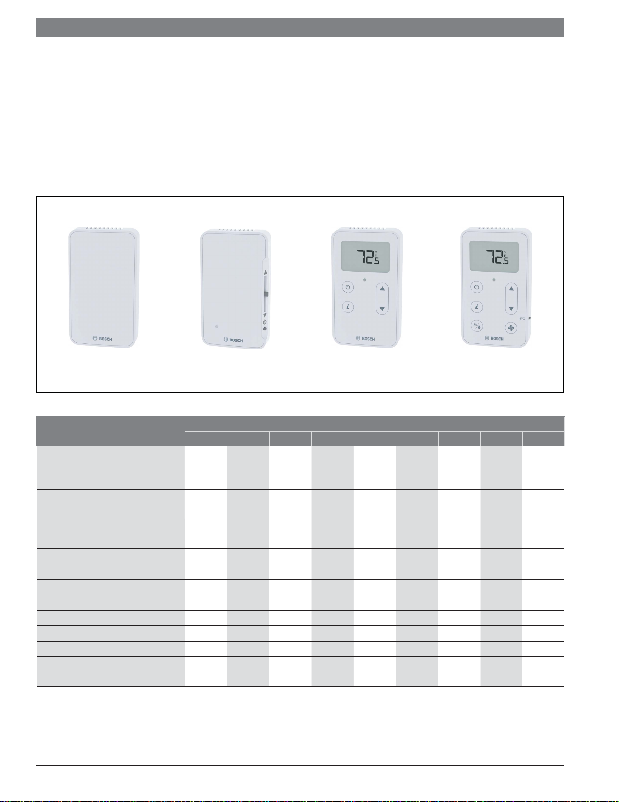
2 Overview
The Bosch line of intelligent zone sensors provides the function and fl exibility needed
to manage the conditions important to the comfort and productivity of the zone
occupants. The ZS series are available in a variety of zone sensing combinations to
address most application needs. These combinations include temperature, relative
humidity, and carbon dioxide (CO2) for indoor air quality (IAQ) improvement.
They are built to be fl exible, allowing for easy customization of what the user/
technician sees. Designed to work with the DDC Control Air 5600, 5830, and 6120
controllers, the ZS sensor line includes the ZS Base, ZS Slidebar, ZS Push, and ZS
Manager.
ZS Base
ZS-1, ZS-1H
Figure 1
ZS Series Sensors
Features
Part Number
Temperature
Humidity
CO2
Neutral color
Addressable / supports daisy-chaining
Hidden communication port
Mounts on standard 2” x 4” electrical box
Occupancy status indicator
Push-button occupancy override
Set-point adjust
Large, easy-to-read LCD
Alarm indicator
Fan Mode Control (ON/AUTO)
System Mode Control (HEAT/COOL/AUTO/OFF)
°F to °C conversion button**
ZS Slidebar
ZS-1S
ZS-1 ZS-1H ZS-1S ZSP-1 ZSP-1H ZSP-1HC ZSM-1 ZSM-1H ZSM-1HC
8733951033 8733951034 8733951035 8733951036 8733951037 8733951038 8733951039 8733951040 8733951041
Table 1
Previously known as FHP560, I/O Zone 583, and FLEX 6126 respectively.
Previously known as ZS Base, ZS Plus, ZS Pro and ZS Pro-F respectively.
* Available only by special request if ordered in 2018.
** Readout only.
ZS Push
ZSP-1, ZSP-1H,
ZSP-1HC
Model
ZS Manager*
ZSM-1, ZSM-1H,
ZSM-1HC
Bosch Thermotechnology Corp. | 02 .2018
Data subject to change
|
6
Bosch ZS Series Zone Sensors R1 Installation & OperationManual
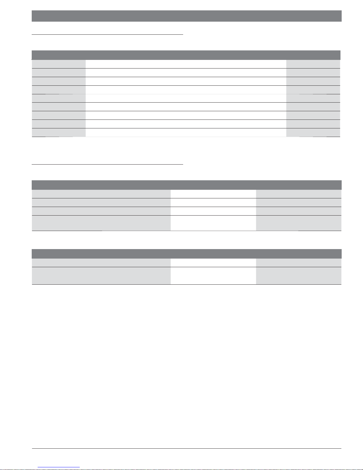
3 Available Models
Sensor Model Description Bosch Part Number
ZS-1
ZS-1H Base Zone Temperature Sensor, with humidity 8733951034
ZS-1S Zone Temperature Sensor with override button, slidebar, occupied LED 8733951035
ZSP-1 Zone Temperature Sensor, Push Button with LCD display, no options 8733951036
ZSP-1H Zone Temperature Sensor, Push Button with LCD display, with humidity 8733951037
ZSP-1HC Zone Temperature Sensor, Push Button with LCD display, with humidity and CO2 8733951038
ZSM-1 Zone Temperature Sensor, Manager with LCD display, no options 8733951039
ZSM-1H Zone Temperature Sensor, Manager with LCD display, with humidity 8733951040
ZSM-1HC Zone Temperature Sensor, Manager with LCD display, with humidity and CO2 8733951041
Base Zone Temperature Sensor, no options 8733951033
Table 2
4 Specifi cations
Sensing Element Range Accuracy
Temperature (On Non-Humidity Models)
Temperature (On Humidity Models) 50° F to 104° F (10° C to 40° C) ±0.5° F (0.3° C)
Humidity 10% to 90% ±1.8% typical
CO2
Table 3
-4°F to 122°F (-20° C to 50°C) ±0.35° F (0.2° C)
400 to 1250 PPM
1250 to 2000 PPM
±30PPM or +/-3% of reading (greater of two)
±5% of reading plus 30 PPM
Power Requirements Sensor Type Power Required
Temperature Only
Temperature/CO2/ Humidity All Models
All Models 12Vdc @ 8mA
12 Vdc @ 15 mA (idle) to 190 mA
(CO2 measurement cycle)
Table 4
Power Supply
A controller supplies the Rnet sensor network with 12 Vdc @ 210 mA.
Additional power may be required depending on the application.
Communication
115 kbps Rnet connection between sensor(s) and controller
5 sensors max per control program (5 sensors can be daisy-chained to one controller
for power averaging)
Local Access Port
For connecting a laptop computer to the local equipment for maintenance and
commissioning
Environmental Operating Range
32° to 122° F (0° to 50° C), 10% to 90% relative humidity, non-condensing
Mounting Dimensions
Standard 2" x 4" electrical box using provided 6/ 32" x 1/2" mounting screws
Data subject to change
02.2018 | Bosch Thermotechnology Corp.
Installation & Operation Manual Bosch ZS Series Zone Sensors R1 | 7
5 Features
The ZS Series Zone Sensors are thermistor-based, communicating temperature
sensors that may optionally sense humidity or CO2 . The ZS Sensors are fi eld
installed and are wired to the Rnet port of the DDC Control Air 5600, 5830, or
6120 controller. A maximum of 5 ZS sensors may be daisy-chained and used for
applications where averaging of multiple readings for temperature is required.
Sensor Features
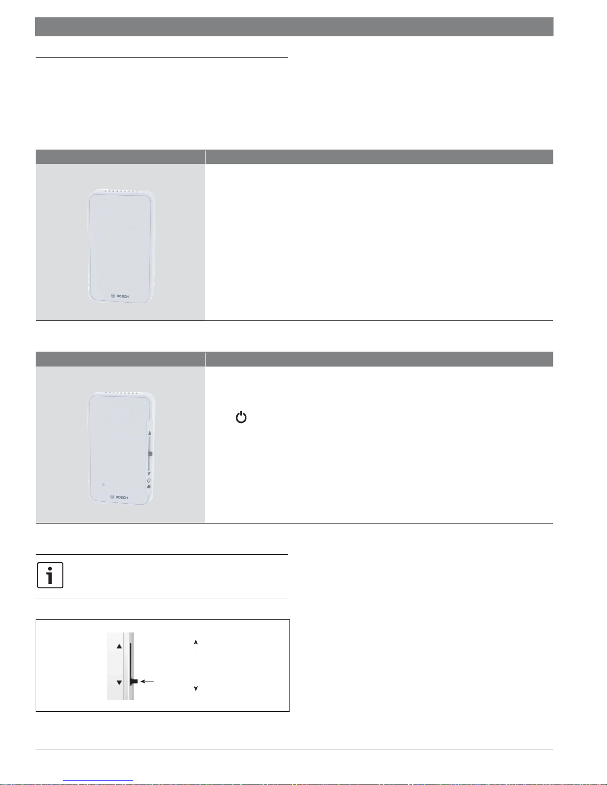
ZS Base
Local access port
No user control
Available in:
— Temperature only: ZS-1 (8733951033)
— Temperature with Humidity: ZS-1H (8733951034)
Table 5
Sensor Features
ZS Slidebar
Table 6
Slide the sensor’s potentiometer up to make the zone warmer or down
to make it cooler. The control program determines how much you can
adjust the set point.(see fi gure# 2)
Slide potentiometer for temperature setpoint adjustment to make the zone warmer or cooler
button to override the schedule and put the zone in an occupied state
Green LED to indicate occupied state
Local access port
Available in:
— Temperature only: ZS-1S (8733951035)
Warme r
Cooler
Slide
Figure 2
Bosch Thermotechnology Corp. | 02 .2018
Data subject to change
|
8
Bosch ZS Series Zone Sensors R1 Installation & OperationManual
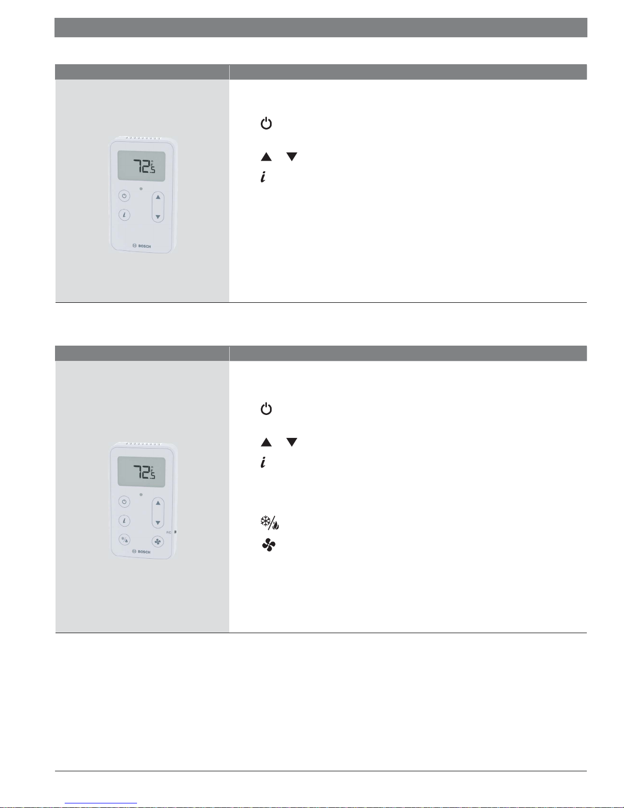
Sensor Features
LCD Display
Table 7
ZS Push
Sensor Features
ZS Manager
button to override the schedule and put the zone in an occupied state, or force the zone to an
unoccupied state
and buttons to change any editable property, such as the temperature or humidity set-point.
button to cycle through information defined in the control program (see Table 11 for more info)
Green LED to indicate occupied state
Local access port
Available in:
— Temperature only: ZSP-1 (8733951036)
— Temperature with Humidity: ZSP-1H (8733951037)
— Temperature with Humidity and CO2 : ZSP-1HC (8733951038)
LCD Display
button to override the schedule and put the zone in an occupied state, or force the zone to an
unoccupied state
and buttons to change any editable property, such as the temperature or humidity set-point.
Table 8
button to cycle through information defined in the control program (see Table 11 for more info)
Green LED to indicate occupied state
Local access port
button to select different system modes (Heat/Cool/Auto/Off).
button to select between two modes of fan operation (Auto/On).
Available in:
— Temperature only: ZSM-1 (8733951039)
— Temperature with Humidity: ZSM-1H (8733951040)
— Temperature with Humidity and CO2 : ZSM-1HC (8733951041)
Data subject to change
02.2018 | Bosch Thermotechnology Corp.
 Loading...