

Bosch ZSB 30-2 A, ZWB 37-2 A Operating Instructions Manual
Operating Instructions
Hydronic Gas Condensing Boiler
Condens 5000 W
6 720 613 085-00.1O
ZSB 30-2 A ...| ZWB 37-2 A ...
6 720 644 144 (2010/09) NZ/AU

2
Contents
6 720 644 144 (2010/09)
Contents
1 Key to symbols and safety instructions . . . . . . . . . . . . . . 4
1.1 Explanation of symbols . . . . . . . . . . . . . . . . . . . . . . . 4
1.2 Safety instructions . . . . . . . . . . . . . . . . . . . . . . . . . . 6
2 Product details . . . . . . . . . . . . . . . . . . . . . . . . . . . . . . . . . 8
2.1 Intended use . . . . . . . . . . . . . . . . . . . . . . . . . . . . . . . 8
2.2 Explanation of model code . . . . . . . . . . . . . . . . . . . . 8
3 Preparing the appliance for use . . . . . . . . . . . . . . . . . . . . 9
3.1 Turn on the gas service cock . . . . . . . . . . . . . . . . . . 9
3.2 Turn on the isolators . . . . . . . . . . . . . . . . . . . . . . . . 10
3.3 Opening the control panel cover . . . . . . . . . . . . . . 11
3.4 Check the central heating system pressure . . . . . . 12
3.5 Top up the heating system . . . . . . . . . . . . . . . . . . . 13
4 Operation . . . . . . . . . . . . . . . . . . . . . . . . . . . . . . . . . . . . . 14
4.1 Overview of controls . . . . . . . . . . . . . . . . . . . . . . . . 16
4.2 Switching the appliance on/off . . . . . . . . . . . . . . . . 18
4.3 Starting the central heating . . . . . . . . . . . . . . . . . . 19
4.4 Setting the heating control unit . . . . . . . . . . . . . . . 21
4.5 Appliances with hot water cylinder:
setting the hot water temperature . . . . . . . . . . . . . . 22
4.6 ZWB appliances - setting hot water temperature . . 24
4.7 Summer mode (central heating off, DHW only) . . . 26
4.8 Frost protection . . . . . . . . . . . . . . . . . . . . . . . . . . . 27
4.9 Holiday mode . . . . . . . . . . . . . . . . . . . . . . . . . . . . . 28
4.10 Further displays . . . . . . . . . . . . . . . . . . . . . . . . . . . 29

3
Contents
6 720 644 144 (2010/09)
5 Carry out thermal disinfection . . . . . . . . . . . . . . . . . . . . . 30
6 Tips on saving energy . . . . . . . . . . . . . . . . . . . . . . . . . . . . 32
7 Troubleshooting . . . . . . . . . . . . . . . . . . . . . . . . . . . . . . . . 34
8 Maintenance . . . . . . . . . . . . . . . . . . . . . . . . . . . . . . . . . . . 36
9 Environment / disposal . . . . . . . . . . . . . . . . . . . . . . . . . . . 37
10 Operating instructions quick reference . . . . . . . . . . . . . . 38
Index . . . . . . . . . . . . . . . . . . . . . . . . . . . . . . . . . . . . . . . . . 39
4 | Key to symbols and safety instructions
6 720 644 144 (2010/09)
1 Key to symbols and safety
instructions
1.1 Explanation of symbols
Warning symbols
Signal words indicate the seriousness of the hazard in terms of the
consequences of not following the safety instructions.
• NOTICE indicates possible damage to property or equipment,
but where there is no risk of injury.
• CAUTION indicates possible injury.
• WARNING indicates possible severe injury.
• DANGER indicates possible risk to life.
Safety instructions in this document are framed
and identified by a warning triangle which is
printed on a grey background.
Electrical hazards are identified by a lightning
symbol surrounded by a warning triangle.
Key to symbols and safety instructions | 5
6 720 644 144 (2010/09)
Important information
Additional symbols
Notes contain important information in cases where
there is no risk of personal injury or material losses
and are identified by the symbol shown on the left.
They are bordered by horizontal lines above and
below the text.
Symbol Meaning
B a step in an action sequence
Æ a reference to a related part in the document or
to other related documents
• a list entry
– a list entry (second level)
Table 1

6 | Key to symbols and safety instructions
6 720 644 144 (2010/09)
1.2 Safety instructions
If you smell gas
B Turn off gas tap (Æ page 16).
B Open windows and doors.
B Do not operate any electrical switches.
B Extinguish any naked flames.
B Leave the building and telephone your gas supply utility and
authorised contractor from an outside phone.
If you smell flue gas from the appliance
B Switch off the appliance (Æ page 16).
B Open windows and doors.
B Inform your heating contractor.
Installation and conversion
B This appliance may only be installed or converted by an
approved installer.
B Never modify any parts of the flue system.
B If the appliance has a type B.. flue system: Do not seal off or
reduce the size of air vents in doors, windows or walls. If
draught-sealed windows are installed, ensure there is an
adequate supply of air to the appliance for combustion.
Thermal disinfection
B Risk of scalding!
It is imperative to monitor operation at temperatures over
60 °C (Æ page 30).

Key to symbols and safety instructions | 7
6 720 644 144 (2010/09)
Risk of damage due to operator error
Operator errors can result in injury and damage to property.
B Ensure that children never operate this appliance unsupervised
or play with it.
B Ensure that only personnel who can operate this appliance
correctly have access to it.
Inspection/Maintenance
B We recommend that you take out a contract to have the
system regularly serviced in order to ensure that it functions
reliably and safely.
B The user is responsible for the general and environmental
safety of the system.
B Only use genuine spare parts!
Combustible materials
B Do not store or use any combustible materials (paper,
thinners, paints etc.) in the vicinity of the appliance.
Combustion air/Ambient air
B Keep combustion air/ambient air free of corrosive substances
(e.g. halogenated hydrocarbons which contain chlorine or
fluorine compounds). In that way corrosion can be prevented.
8 | Product details
6 720 644 144 (2010/09)
2 Product details
2.1 Intended use
The appliance may only be installed in sealed hot-water central
heating systems to EN 12828.
Using the appliance for any other purpose will be considered
incorrect use. Bosch accepts no liability for any damage resulting
from such use.
The commercial and industrial use of appliance to generate
process heat is not permitted.
2.2 Explanation of model code
Z Central heating appliance
S Cylinder connection
W DHW heating
B Condensing boiler technology
30 Output up to 30 kW
37 DHW output up to 37 kW
-2 Version
A Fan-assisted appliance without draught hood
Condens 5000 W ZSB 30-2 A
ZWB 37-2 A
Table 2
Preparing the appliance for use | 9
6 720 644 144 (2010/09)
3 Preparing the appliance for use
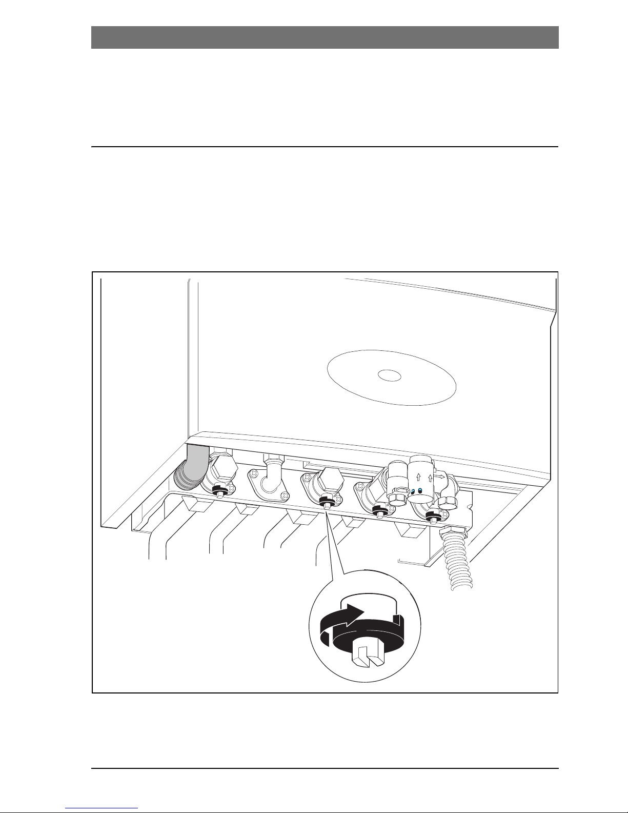
3.1 Turn on the gas service cock
B Using a screwdriver, turn the square tap handle so that the slot
is in line with the direction of flow.
Slot at right-angles to direction of flow = off.
Fig. 1
6 720 644 144-01 .1O
10 | Preparing the appliance for use
6 720 644 144 (2010/09)
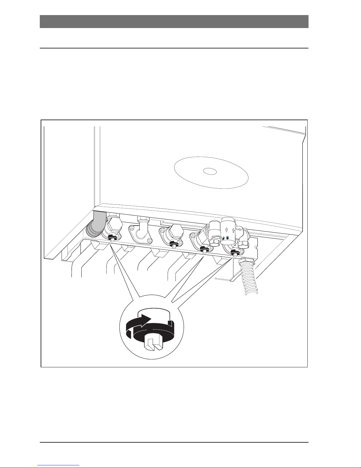
3.2 Turn on the isolators
B Using a screwdriver, turn the square tap handle so that the slot
is in line with the direction of flow.
Slot at right-angles to direction of flow = off.
Fig. 2
6 720 644 143-02.1O
Preparing the appliance for use | 11
6 720 644 144 (2010/09)
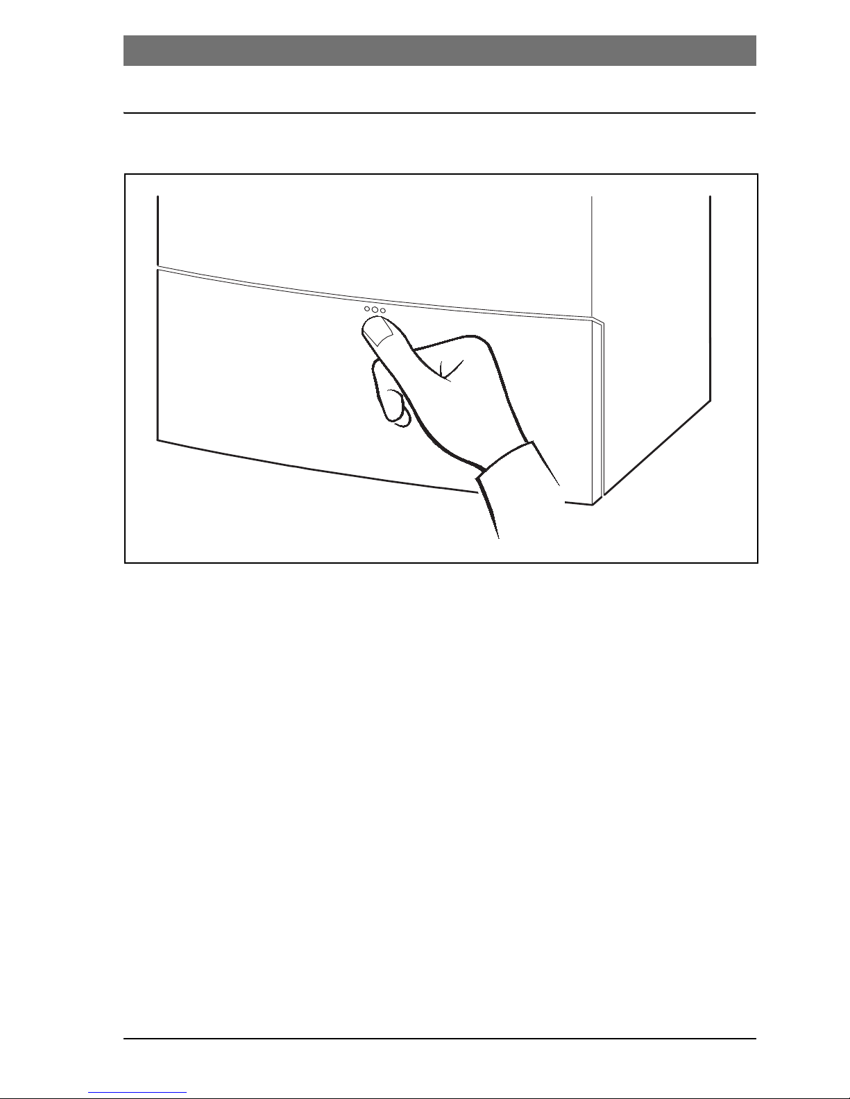
3.3 Opening the control panel cover
Fig. 3
6 720 612 660-01.2R
12 | Preparing the appliance for use
6 720 644 144 (2010/09)
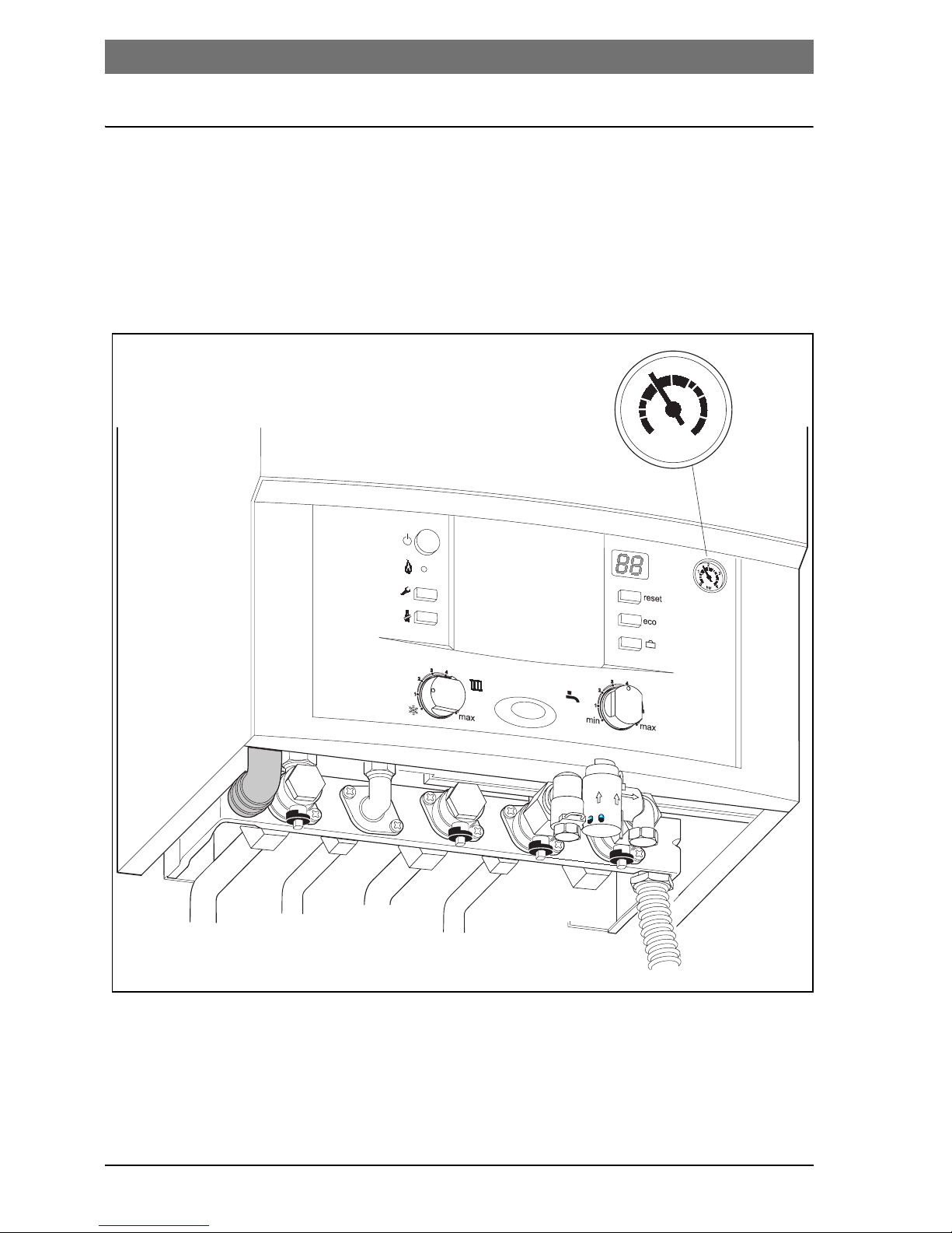
3.4 Check the central heating system pressure
The normal operating pressure is 1 - 2 bar.
If a higher setting is required, you will be informed by your
installer.
Fig. 4
6 720 644 144-03.1O
1
0
2
3
4
bar

Preparing the appliance for use | 13
6 720 644 144 (2010/09)
3.5 Top up the heating system
The way in which the heating system is topped up is different on
every system. Therefore, you should ask your installer to show you
how it is done.
Maximum pressure of 3 bar at maximum heating water
temperature must not be exceeded (safety valve will open).
CAUTION: Risk of damaging the appliance.
B Only top up the heating system when the
appliance is cold.
14 | Operation
6 720 644 144 (2010/09)
4 Operation
These Operating Instructions apply only to the boiler.
Depending on the heating controller used, some functions may be
controlled differently.
The following possibilities for controlling the heating system may
be employed:
• weather-dependent controller built into the boiler Æ page 16,
item 7.
• weather-dependent controller external to the appliance
• room thermostat
Therefore, please read the operating instructions
for the heating controller used.
 Loading...