

Bosch ZSB18, Condens 5000W Installation And Servicing Instructions
Installation and Servicing Instructions
HYDRONIC GAS SYSTEM BOILER 18kW
BOSCH CONDENS 5000W
6720646195-00.1Wo
ZSB18 - 2A
6 720 646 195a (2010/11)

2 | Contents AU/NZ
6 720 646 195a (2010/11)
Contents
1 Key to symbols and safety precautions . . . . . . . . 3
1.1 Explanation of symbols . . . . . . . . . . . . . . . 3
1.2 Safety precautions . . . . . . . . . . . . . . . . . . 4
2 Boiler information . . . . . . . . . . . . . . . . . . . . . . . . 6
2.1 Boiler . . . . . . . . . . . . . . . . . . . . . . . . . . . . 6
2.2 Technical data . . . . . . . . . . . . . . . . . . . . . 7
2.3 Layout . . . . . . . . . . . . . . . . . . . . . . . . . . . . 8
3 Pre-installation . . . . . . . . . . . . . . . . . . . . . . . . . . 11
3.1 Cleaning primary systems . . . . . . . . . . . . 11
3.2 Mains supply . . . . . . . . . . . . . . . . . . . . . . 12
3.2.1 Electrical supply . . . . . . . . . . . . . . . . . . . 12
3.2.2 Equipotential (earth) bonding . . . . . . . . 12
3.2.3 Gas supply . . . . . . . . . . . . . . . . . . . . . . . 12
3.3 Water system and pipe work . . . . . . . . . 13
3.4 Condensate pipe work . . . . . . . . . . . . . . 15
3.4.1 Internal connections . . . . . . . . . . . . . . . . 15
3.4.2 External connections . . . . . . . . . . . . . . . 16
3.5 Pressure relief drain line . . . . . . . . . . . . 17
3.6 Boiler location and clearances . . . . . . . . 18
3.6.1 Installation . . . . . . . . . . . . . . . . . . . . . . . 18
3.6.2 Servicing clearances
- Ventilated compartment . . . . . . . . . . . 18
3.6.3 Compartments . . . . . . . . . . . . . . . . . . . . 18
3.6.4 Boiler clearances
- Unventilated compartments . . . . . . . . 19
3.6.5 Installation clearances
- Unventilated compartments . . . . . . . . 19
3.7 Plumbing manifold . . . . . . . . . . . . . . . . . 20
3.7.1 Connections . . . . . . . . . . . . . . . . . . . . . . 20
3.8 Flue options . . . . . . . . . . . . . . . . . . . . . . 21
3.9 Flue terminal positions . . . . . . . . . . . . . . 23
3.10 Plume management terminal positions . 24
4 Installation . . . . . . . . . . . . . . . . . . . . . . . . . . . . . 25
4.1 Unpacking wall frame & ancillary items . 25
4.2 Wall mounting template & flue opening . 26
4.3 Unpacking the boiler . . . . . . . . . . . . . . . . 27
4.4 Boiler connections . . . . . . . . . . . . . . . . . 28
4.5 Flue installation . . . . . . . . . . . . . . . . . . . 30
4.5.1 Measuring the flue (standard flue) . . . . . 30
4.5.2 Reducing the telescopic flue length . . . . 30
4.5.3 Installing the telescopic flue . . . . . . . . . . 31
4.5.4 Flue terminal plume re-direction . . . . . . 32
4.6 Condensate connection . . . . . . . . . . . . . 33
4.7 Electrical . . . . . . . . . . . . . . . . . . . . . . . . . 34
5 Commissioning . . . . . . . . . . . . . . . . . . . . . . . . . . 36
5.1 Pre-commissioning checks . . . . . . . . . . . 36
5.2 Filling the system . . . . . . . . . . . . . . . . . . 37
5.3 Water treatment . . . . . . . . . . . . . . . . . . . 37
5.4 Starting the boiler . . . . . . . . . . . . . . . . . 38
5.5 Commissioning . . . . . . . . . . . . . . . . . . . 39
5.5.1 Checking the gas inlet pressure . . . . . . 39
5.5.2 Checking the gas rate . . . . . . . . . . . . . . 40
5.5.3 Domestic hot water: . . . . . . . . . . . . . . . 40
5.6 Finishing commissioning . . . . . . . . . . . . 41
5.6.1 Replace outer casing: . . . . . . . . . . . . . . 41
5.6.2 Fitting fascia flap . . . . . . . . . . . . . . . . . . 41
5.6.3 Installing bottom panel . . . . . . . . . . . . . 41
5.6.4 Handover . . . . . . . . . . . . . . . . . . . . . . . . 41
6 Service and spares . . . . . . . . . . . . . . . . . . . . . . 42
6.1 Inspection and service . . . . . . . . . . . . . 42
6.2 Check the gas inlet pressure . . . . . . . . . 43
6.3 Checking flue integrity . . . . . . . . . . . . . 43
6.4 Fan pressure test . . . . . . . . . . . . . . . . . 44
6.5 Flue gas analysis . . . . . . . . . . . . . . . . . . 45
6.6 Setting the air/gas ratio . . . . . . . . . . . . 46
6.6.1 Setting the CO/CO2 . . . . . . . . . . . . . . . 46
6.7 Cleaning the heat exchanger . . . . . . . . . 47
6.8 Replacement of parts . . . . . . . . . . . . . . 50
6.8.1 Removing outer case . . . . . . . . . . . . . . . 50
6.8.2 Primary sensor . . . . . . . . . . . . . . . . . . . 50
6.8.3 Overheat thermostat . . . . . . . . . . . . . . . 50
6.8.4 Flue overheat thermostat
(with grommet) . . . . . . . . . . . . . . . . . . . 51
6.8.5 Moving controls to service position . . . 51
6.8.6 Gas valve . . . . . . . . . . . . . . . . . . . . . . . . 52
6.8.7 Air/gas manifold and fan assembly . . . . 52
6.8.8 Fan . . . . . . . . . . . . . . . . . . . . . . . . . . . . 53
6.8.9 Electrode assembly and burner . . . . . . . 54
6.8.10 Heat exchanger . . . . . . . . . . . . . . . . . . . 54
6.8.11 Access to boiler control components . . 56
6.8.12 PCB Fuse . . . . . . . . . . . . . . . . . . . . . . . . 56
6.8.13 Transformer/PCB . . . . . . . . . . . . . . . . . 56
6.8.14 Replacing controls . . . . . . . . . . . . . . . . 57
6.8.15 Syphon removal . . . . . . . . . . . . . . . . . . . 58
6.8.16 Diverter valve motor (If fitted) . . . . . . . 58
6.8.17 Diverter valve (If fitted) . . . . . . . . . . . . . 58
6.8.18 Auto air vent . . . . . . . . . . . . . . . . . . . . . 59
6.8.19 Pump head . . . . . . . . . . . . . . . . . . . . . . 59
6.8.20 Drain tap . . . . . . . . . . . . . . . . . . . . . . . . 59
6.8.21 Pressure gauge . . . . . . . . . . . . . . . . . . . 60
6.8.22 Hydraulic block removal . . . . . . . . . . . . 60
6.8.23 CH Pressure relief valve . . . . . . . . . . . . 61
6.8.24 Bypass valve . . . . . . . . . . . . . . . . . . . . . 61
6.8.25 Expansion vessel . . . . . . . . . . . . . . . . . . 61
6.9 Short parts list . . . . . . . . . . . . . . . . . . . 63
7 Fault finding and diagnosis . . . . . . . . . . . . . . . 64
7.1 Fault finding . . . . . . . . . . . . . . . . . . . . . 64
7.1.1 Circuit diagram . . . . . . . . . . . . . . . . . . . 67
7.2 Boiler function . . . . . . . . . . . . . . . . . . . . 68
7.3 Protection function . . . . . . . . . . . . . . . . 69
KEY TO SYMBOLS AND SAFETY PRECAUTIONS | 3AU/NZ
6 720 646 195a (2010/11)
1 KEY TO SYMBOLS AND SAFETY PRECAUTIONS
1.1 Explanation of symbols
Warning symbols
Signal words indicate the seriousness of the hazard in
terms of the consequences of not following the safety
instructions.
• NOTICE indicates possible damage to property or
equipment, but where there is no risk of injury.
• CAUTION indicates possible injury.
• WARNING indicates possible severe injury.
• DANGER indicates possible risk to life.
Important information
Additional symbols
SYMBOLS USED IN THIS MANUAL
PLEASE READ THESE INSTRUCTIONS CAREFULLY
BEFORE STARTING INSTALLATION.
This installation manual is only applicable to the model
of boiler stated on the front cover of this manual.
This boiler must be installed by an authorised person
only. Failure to install this boiler correctly could lead to
prosecution.
If you are in any doubt contact the Robert Bosch
technical hotline on:
1300 30 70 37 AU or 0800 54 33 52 NZ
Please leave these instructions, completed installation
checklist and user manual with the customer after
installing the boiler.
The checklist can be found in the back pages of this
manual.
Abbreviations used in this manual:
Safety instructions in this document are
framed and identified by a warning triangle
which is printed on a grey background.
Electrical hazards are identified by a
lightning symbol surrounded by a warning
triangle.
Notes contain important information in
cases where there is no risk of personal
injury or material losses and are identified
by the symbol shown on the left. They are
bordered by horizontal lines above and
below the text.
Symbol Meaning
B a step in an action sequence
Æ a reference to a related part in the
document or to other related documents
• a list entry
– a list entry (second level)
Tab. 1 Symbols
Domestic hot water
Central heating
Hot water storage cylinder
Domestic cold water supply
Electrical supply
Gas supply
Tab. 2 Commonly used symbols
ØDiameter
NG Natural gas
LPG Liquefied petroleum gas
CH Central heating
DHW Domestic hot water
PCB Printed circuit board
PRV Pressure relief valve
NTC Negative temperature coefficient (sensor)
IP Ingress protection
RCD Residual current device
TRV Thermostatic radiator valve
approx. Approximate
BSP British standard pipe
pH Potential hydrogen
PVC Poly vinyl chloride
RSF Room sealed flue
kPa kilo Pascals
Tab. 3 Abbreviations

4 | KEY TO SYMBOLS AND SAFETY PRECAUTIONS AU/NZ
6 720 646 195a (2010/11)
1.2 Safety precautions
If you smell gas:
B CALL THE FEDERAL GOVERNMENTS SAFETY
HOTLINE ON 13 17 92
B LPG BOILERS CALL THE SUPPLIER‘S NUMBER ON
THE SIDE OF THE LPG TANK/CYLINDER
B TURN OFF THE ECV (EMERGENCY CONTROL VALVE)
AT THE METER
B DO NOT TURN ELECTRICAL SWITCHES ON OR OFF
B DO NOT STRIKE MATCHES OR SMOKE
B PUT OUT NAKED FLAMES
B OPEN DOORS AND WINDOWS
B KEEP PEOPLE AWAY FROM THE AFFECTED AREA
Boiler operation
This boiler must only be operated by a responsible
adult who has been instructed in, understands, and is
aware of the boiler's operating conditions and effects.
Service checklist
The Service Checklist places responsibilities on both
manufacturers and installers. The purpose is to ensure
that customers are provided with the correct equipment
for their needs, that it is installed, commissioned and
serviced in accordance with the manufacturer's
instructions by authorised persons and meets the
requirements of the appropriate building regulations.
The service checklist can be used to demonstrate
compliance with building regulations and should be
provided to the customer for future reference.
Combustion and corrosive materials
Do not store or use any combustible materials (paper,
thinners, paints etc.) inside or within the vicinity of the
boiler.
Chemically aggressive substances can corrode the boiler
and invalidate any warranty.
Fittings and modifications
Fitting the boiler and any controls may only be carried
out by an authorised person.
Flue systems must not be modified in any way other than
as described in the fitting instructions. Any misuse or
unauthorised modifications to the boiler, flue or
associated components and systems could invalidate
the warranty. The manufacturer accepts no liability
arising from any such actions, excluding statutory rights.
Servicing
Advise the user to have the system serviced annually by
an authorised person. Approved spar es must be used to
help maintain the economy, safety and reliability of the
boiler.
Important
The service engineer must complete the Service Record
at the rear of this manual after each service.
Installation regulations
All gas boilers must be installed by an authorised person
in accordance with AS 3000, AS 5601 and building
regulations of relevant states and territories.
Failure to install boilers correctly could lead to
prosecution.
Standards
Where no specific instruction is given, reference should
be made to the following standards:
• AS 5601 Gas Installations,
• AS 1596 LPG storage and handling,
• AS 4552 Gas fired water heaters for hot water supply
and/or central heating,
• AS/NZS 3000 Electrical Installations,
• AS1697 Installation and maintenance of steel pipe
systems for gas,
• AS 4032 Water supply - valves for the control of hot
water supply temperatures,
• AS 3498 Authorization requirements for plumbing
products - water heaters and hot-water storage tanks.
• AS 1910 Water supply - float control valves for use in
hot and cold water, AS 3500 National plumbing and
drainage code.
Liquefied petroleum gas
A boiler using LPG gas must not be installed in a room or
internal space below ground level unless one side of the
building is open to the ground.

KEY TO SYMBOLS AND SAFETY PRECAUTIONS | 5AU/NZ
6 720 646 195a (2010/11)
Boiler features and checklist
• Pre-wired and pre-plumbed
• Galvanised steel inner frame
• Digital control system
• Intelligent controls
• Automatic ignition
• Direct burner ignition electrodes
• Built-in frost protection
• Built-in fault finding diagnostics
• Modulating automatic gas valve
• Combustion air fan with speed regulator
• CH temperature sensor & control
• Pump anti-seizure protection
• Flue gas temperature sensor
• Condensate syphonic trap
• Temperature control
Check list
- Hardware literature pack:
Qty.
Installation instructions 1
User instructions 1
Warranty card 1
Sealing pack: 1
- Compression nut 22mm 3
- Compression ring 22mm 3
- Compression nut 15mm 3
- Compression ring 15mm 3
- Fibre washer 18.6 x 13.5 x 1.5 2
- Fibre washer 23.9 x 17.2 x 1.5 2
- Bonded washer 3/4“ for gas 1
Adapter, 22mm to R¾ 3
Adapter, 15mm to R½ 1
Syphon assembly 1
Warranty return envelope 1
Tab. 4 Checklist
6 | Boiler information AU/NZ
6 720 646 195a (2010/11)
2 Boiler information
2.1 Boiler
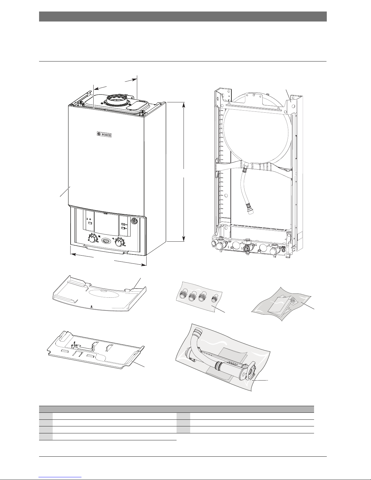
Fig. 1 Boiler carton contents
Standard package:
1 Hydronic system boiler 5 Fascia panel
2 Wall mounting frame 6Syphon assembly
3 Hardware literature pack (see checklist) 7 Metric to Imperial adapter pack
4 Bottom panel
2
4
3
5
* 710mm to top of case front
1
700mm*
400mm
330mm
Depth to wall
(When tted to wall frame)
6
6720646195-01.1Wo
7
Boiler information | 7AU/NZ
6 720 646 195a (2010/11)
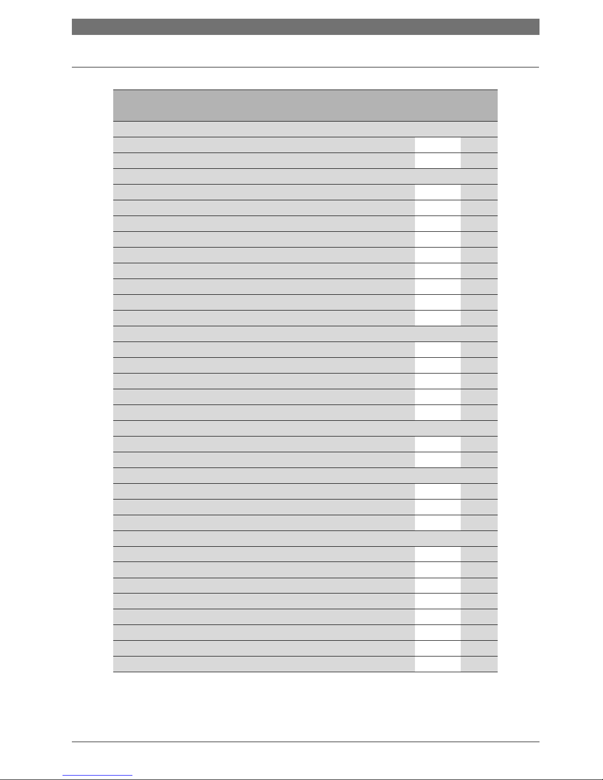
2.2 Technical data
Description Natural gas
UNIT 18kW
Gas flow rate - Max. 10 minutes from lighting
Natural gas G20 MJ/h 73.84
Liquefied petroleum gas (LPG) kg/h -
Central heating
Maximum rated heat input (net) kW 18.48
Minimum heat input kW 5.54
Max. rated heat output 40/30 °C kW 19.28
Max. rated heat output 50/30 °C kW 19.11
Max. rated heat output 80/60 °C kW 18
Max. flow temperature °C 82
Max. flow temperature to cylinder (with integral optional diverter valve) °C 75
Max. permissible operating pressure kPa 250
Available pump head at 21 °C system temp. rise m 2.0
Flue
Flue gas temp. 80/60 °C, rated/min. load °C 70/60
Flue gas temp. 40/30 °C, rated/min. load °C 48/34
CO2 level at max. rated heat output (after 30 min) % 9.8
CO2 level at min. rated heat output (after 30 min) % 9.2
NOx class 4
Condensate
Maximum condensate rate l/h 1.5
pH value, approx. 4.8
Electrical
Electrical power supply voltage a.c. V 240
Frequency Hz 50
Maximum power consumption W 140
General data
Star Rating
Permissible ambient temperatures °C 0 - 50
Nominal capacity of boiler litre 3.9
Noise output level (Max central heating) dBA 42
Packaged boiler weight kg 41
Total boiler weight kg 37.5
Lift weight kg 27.1
Efficency
Tab. 5 Technical data Condens 5000
8 | Boiler information AU/NZ
6 720 646 195a (2010/11)
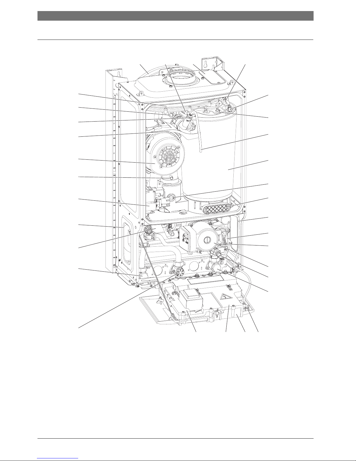
2.3 Layout
Fig. 2 Main boiler components
6720644743-02.1Wo
12
31
30
29
28
27
26
10
14
12
11
13
15
16
25
23
24
22
21
20
19
18
17
34
5
6
7
8
9
Boiler information | 9AU/NZ
6 720 646 195a (2010/11)
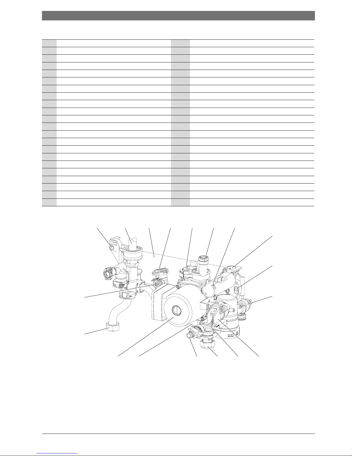
Fig. 3 Hydraulic block components
1 Expansion vessel 23 Hydraulic block mounting plate
2 Sensor - boiler flow 24 Left side hand-hold for lifting boiler
3 Removable panel - for servicing 25 Gas valve
4 Electrode assembly 26 Flue air pressure switch connection (not used)
5 Overheat thermostat 27 Fan
6 Securing nut - air/gas manifold clamp 28 Fan guard
7 Silicon tube - heat exchanger air vent 29 Manual vent point
8 Heat exchanger 30 Fan pressure test point
9 Flue over heat thermostat 31 Air/gas manifold
10 Access panel - heat exchanger/sump cleaning 32 Compact hydraulic - left mounting point
11 Right side hand-hold for lifting boiler 33 Flow connector from heat exchanger
12 Diverter valve assembly (body) 34 Expansion vessel hose connection point
13 Diverter valve actuator (stepper motor) 35 Auto air vent
14 Pump 36 Return connection to heat exchanger
15 Drain point 37 Flow turbine housing (not used)
16 CH return isolator 38 Unused port
17 System pressure gauge 39 Compact hydraulic - right mounting point
18 Control panel (in service position) 40 Pressure relief valve
19 Cover - external wiring connections 41 CH return connection to service valve
20 Cover - transformer and PCB 42 Internal by-pass
21 Gas inlet connection BSP ¾ inch thread 43 CH flow connection to service valve
22 CH flow isolator 44 Pressure gauge connection point
Tab. 6 Boiler components
6720644743-03.1Wo
32 33 23 3534 36 37
38
39
40
44
43
12
42 15 41
14
13
10 | Boiler information AU/NZ
6 720 646 195a (2010/11)
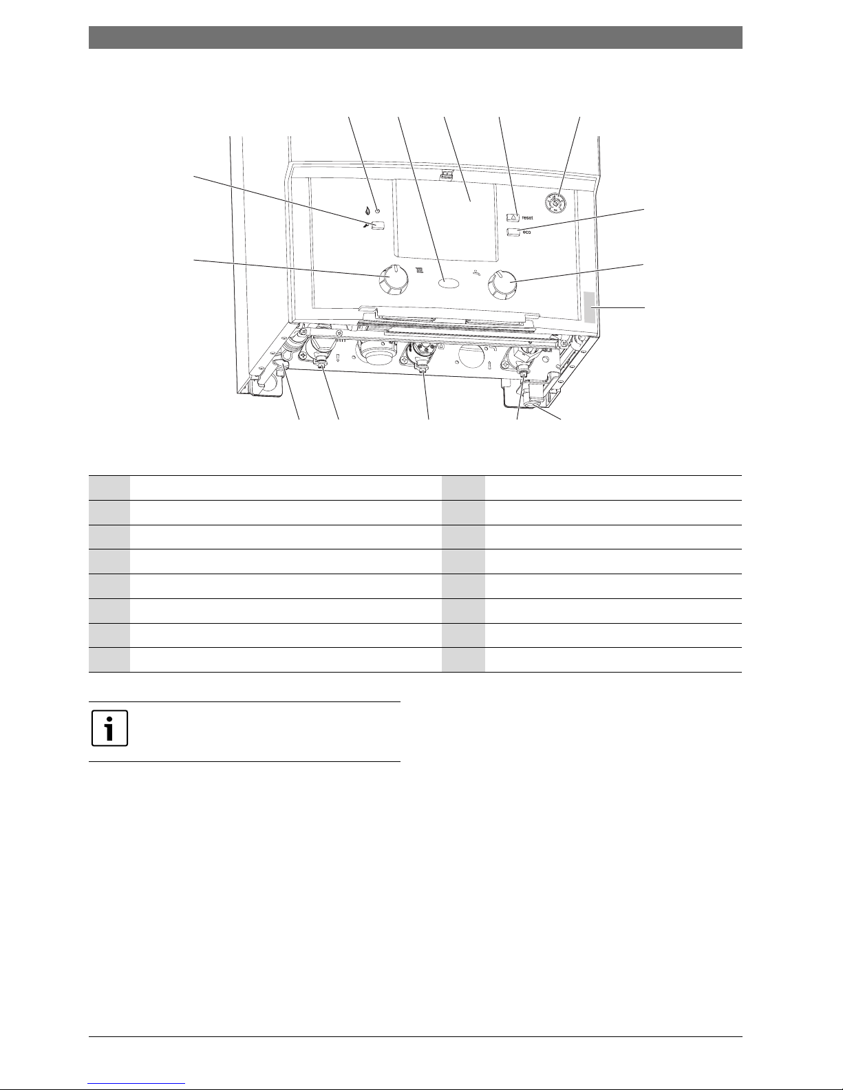
Fig. 4 Additional components
1 Burner ON indicator light (green) 9 PRV pipe connection point
2 Power ON/OFF indicator/fault diagnostic light (blue) 10 CH return isolator
3 Position for optional programmer 11 Gas inlet connection BSP ¾ inch thread
4 Reset button 12 CH flow isolator
5System pressure gauge 13 Condensate connection
6 ECO button (not used) 14 CH temperature control
7 DHW temperature control* 15 Service mode button
8 Boiler identification label
Tab. 7 Additional boiler components
6720644743-04.1Wo
123
45
6
15
14
91011
13
12
7
8
* The DHW temperature control is only
operational when the “optional internal
diverter valve” is fitted.
Pre-installation | 11AU/NZ
6 720 646 195a (2010/11)
3 Pre-installation
3.1 Cleaning primary systems
Before cleaning the system:
B Ensure the system and pipe work are in good working
order.
B Where possible keep the existing boiler/circulating
pump in place when flushing the system.
Flushing the system
B Fill the system with cold water and check for leaks.
B Open all drain points and drain the system.
B Close drain points and add a suitable flushing agent
compatible with aluminium at the correct strength
for the system conditions in accordance with the
manufacturer‘s instructions.
The pH value of the system water must be less than
8 or the boiler guarantee will be invalidated.
B Circulate the flushing agent before the boiler is fired
up.
B Run the boiler/system at normal operating
temperature as directed by the manufacturer of the
flushing agent.
B Drain and thoroughly flush the system to remove the
flushing agent and debris.
B It may be necessary to use a power flushing machine
to aid the cleansing procedure in some
circumstances.
B Close the drain points and refill with fresh water and
a suitable inhibitor.
B Vent any air from the boiler and system.
Inhibitor
Add a suitable inhibitor or combined inhibitor/antifreeze, if the system is exposed to freezing conditions, to
the heating system in accordance with the
manufacturer‘s guidelines.
NOTE:
B All the following pre-installation sections
must be read and requirements met
before starting boiler or flue installations.
CAUTION:
B Isolate the mains supplies before starting
any work and observe all relevant safety
precautions.
NOTE:
Debris from the system can damage the
boiler and reduce efficiency.
Failure to comply with the guidelines for the
use of water treatment with the boiler will
invalidate the warranty.
NOTE: Artificially softened water must not
be used to fill the CH system.
WARNING: Sealing agents
B The addition of sealing agents to the
system water is not permitted as this may
block the heat exchanger.

12 | Pre-installation AU/NZ
6 720 646 195a (2010/11)
3.2 Mains supply
3.2.1 Electrical supply
• Supply: 240V - 50 Hz, 140 Watts
• Cable: PVC insulated 0.75 mm
2
(24 x 0.2 mm)
temperature rated to 90 °C.
• External 3A fuse.
• The boiler must be earthed.
• This boiler must not be connected to a three phase
supply.
• IPX4D.
• Wiring must comply with AS/NZS 3000 Electrical
Installations.
3.2.2 Equipotential (earth) bonding
Main equipotential bonding is carried at the origin of the
electrical installation.
Supplementary bonding is carried out in an area of
increased shock risk e.g. bathrooms.
Metal pipes can be used as bonding conductors if joints
are metal to metal and electrically continuous.
Wiring regulations require that extraneous conductive
parts must be connected to the main electrical earth.
The main bonding of incoming metallic services must be
as close as practical to their entry point, before any
branch pipe work and a maximum of 600mm from an
internal meter.
Earth bond conductors must be copper and the same
size as other earth bonding conductors and not be less
than 10mm
2
.
The earth bond conductors must be permanently fixed
to the metal pipes with clamps and labels in a visible
position to allow for inspection.
3.2.3 Gas supply
• Boilers using natural gas (NG) must be connected to
a governed meter.
• Liquefied petroleum gas (LPG) must be connected to
a regulator or governed meter.
• Installation and connection of the gas supply to the
boiler must be in accordance with AS 5601.
• Under no circumstance should the size of the gas
supply pipe be less than the inlet on the boiler.
• The meter or regulator and pipe work to the meter
must be checked, preferably by the gas supplier.
This is to ensure that the equipment is in good
working order and can meet the gas flow and
pressure requirements and demand from any other
appliance being served.
Pre-installation | 13AU/NZ
6 720 646 195a (2010/11)
3.3 Water system and pipe work
Plastic pipe work:
• Any plastic pipe work must have a polymeric barrier
with 600mm (minimum) length of copper pipe
connected to the boiler.
• Pl a s t i c pipe wor k us e d f o r underfl oor h e a ting must b e
correctly controlled with a thermostatic blending
valve limiting the temperature of the circuits to
approximately 50 °C.
Primary systems connections/valves:
• All system connections, taps and mixing valves must
be capable of sustaining a pressure up to 3 bar.
• Bosch recommends that thermostatic radiator valves
(TRV’s) be used on all radiators within the sleeping
accommodation but not the radiator where the room
thermostat is sited. This must be fitted with lockshield valves and left open.
• A drain point is required at the lowest part of the
system.
• An air vent is required at all the high points in the
system.
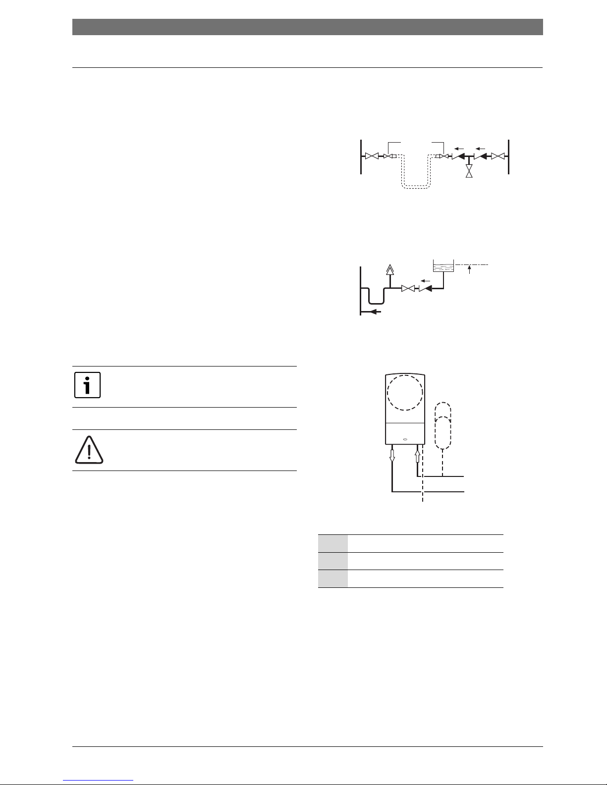
Sealed primary system:
• The CH sealed system must be filled using an
approved filling loop or comply with figure 5 for
system fill.
• Where the system volume is more than 100 litres or
exceeds 265 kPa at maximum heating temperature,
an extra expansion vessel (2) must be fitted as close
as possible to the boiler in the central heating return.
• Pressurise the extra expansion vessel (2) to the same
figure as the expansion vessel built into the boiler.
• Do not use galvanised pipes or radiators.
System fill
Fig. 5 System fill
Fig. 6 Additional expansion vessel
The boiler is equipped with an automatic
internal by-pass.
NOTE: Artificially softened water must not
be used to fill the CH system.
1 boiler expansion vessel - CH
2 Extra expansion vessel - CH return
3 Pressure relief discharge
Tab. 8 Key to fig. 5
SYSTEM FILL
CV = Check Valve
SV = Stop Valve
SV SV
Test point
Temporary hose
Hose union
CV
CV
Heating
return
Mains
supply
SYSTEM MAKE UP
AA = Auto Air vent
CV = Check Valve
SV = Stop Valve
SV
CV
AA
Make up
vessel
Heating
return
1000 mm (39 in)
above the highest
point of the system.
Fill point
6720644743-08.1Wo
1
2
3
6720644743-09.1Wo
14 | Pre-installation AU/NZ
6 720 646 195a (2010/11)
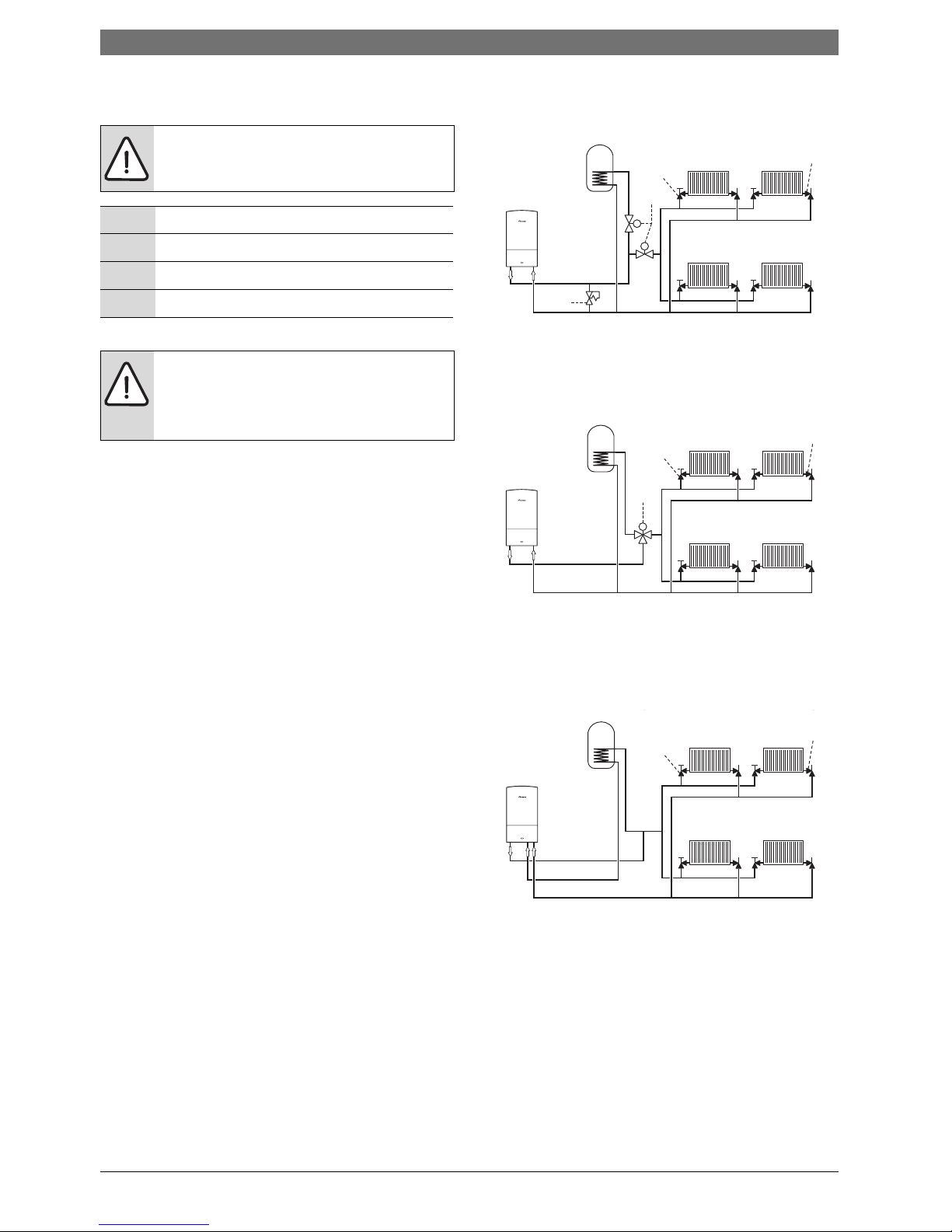
S and Y plan systems:
Optional diverter valve
This boiler is designed to operate on a sealed system
only and will require a second return pipe from the water
cylinder to the wall mounting frame.
S plan layout
Fig. 7 S plan
Y plan layout
with external diverter valve
Fig. 8 Y plan
System layout
with optional internal diverter valve
(not supplied with boiler)
Fig. 9 System layout
NOTE: The boiler is fitted with its own
internal bypass.
1 Diverter valve
2 Radiator valve (flow)
3 Lock shield valve (return)
4Bypass
Tab. 9
NOTE:
B A drain point should be fitted at the
lowest part of the heating circuit and
beneath the boiler.
3
2
1
4
M
M
6720644743-05.1Wo
3
2
1
M
6720644743-06.1Wo
Boiler flow
Cylinder return
Heating return
()
3
2
6720644743-07.1Wo
Pre-installation | 15AU/NZ
6 720 646 195a (2010/11)
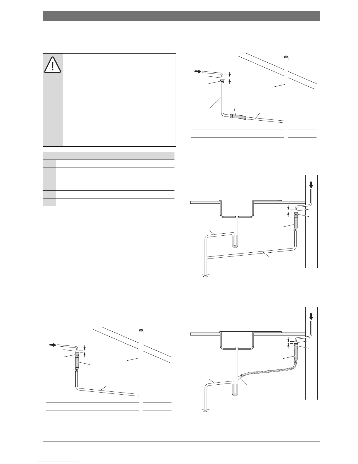
3.4 Condensate pipe work
3.4.1 Internal connections
Where there is the possibility of freezing conditions and
In order to minimise the freezing risk during prolonged
cold spells, the following methods of installing
condensate drainage pipe should be adopted, in order of
priority.
Wherever possible, the condensate drainage pipe should
be routed and terminated so that the condensate drains
away from the boiler under gravity to a suitable internal
soil and vent stack. A suitable permanent connection to
the foul waste pipe should be used.
A self sealing device should be incorporated in the
drainage path, if possible, in an upright position.
A tundish should be used as a suitable air gap just before
the self sealing device. The self sealing device can be
used on a gradient as long as it preceded by a vertically
mounted tundish.
Fig. 10 Disposal to soil vent stack - vertical position
Fig. 11 Disposal to soil vent stack - on gradient
Alternatively if the first option is not possible an internal
kitchen or bathroom waste pipe can be used.
Fig. 12 Disposal to a waste pipe
A washing machine waste pipe or bifurcated pipe etc.
can also be used.
Fig. 13 Bifurcated pipe disposal
NOTE:
BWhere a new or replacement boiler is being
installed and freezing conditions are
possible, access to an internal “gravity
discharge” point should be one of the
factors considered in determining boiler
location.
BThe condensate pipe must be a minimum of
40 mm Ø plastic pipe.
BThe condensate pipe work must fall at least
50 mm per metre towards the outlet and
should take the shortest practicable route.
BEnsure that there are no blockages in the
pipe run.
Key to condensate illustrations
1 Condensate discharge
2 Air gap (20mm)
3Tundish
4Self sealing device
5 Dishwasher connection
6Vent stack
20mm
1
40mm Ø
2
3
6
4
6720646195-18.1Wo
6720646195-19.1Wo
20mm
1
40mm Ø
40mm Ø
2
3
6
4
20mm
1
40mm Ø
40/50mm Ø
4
2
3
6720646195-16.1Wo
20mm
1
40/50mm Ø
4
2
5
3
6720646195-17.1Wo
16 | Pre-installation AU/NZ
6 720 646 195a (2010/11)
3.5 Pressure relief drain line
• The pressure relief valve and control valve shall be
fitted with a drain line that shall be of copper or other
suitable pipping and be of a diameter not smaller than
the nominal size of the valve outlet as per AS/NZS
3500.
• Drain line (1) should be finished with a partial bend,
near the outlet to face the external wall (as shown) to
help prevent freezing.
1. Pressure relief discharge pipe can be between 200
and 300mm above a paved area
2. Pressure relief discharge pipe can be between 75 and
300mm when discharging into a gravel pit of not less
than 100mm diameter.
Fig. 14 Pressure relief pipe work
NOTE:
B The PRV is a safety device for the boiler
and if activated may discharge boiling
water steam through the relief valve drain
line.
B Care should be taken when siting the
drain line so that it does not cause an
obstruction or discharge above a
window, entrance or other public access
where it could cause a hazard.
1 Paved area
2 Gravel pit not less than 100mmØ
Tab. 10 Key to fig 14
6720646195-20.1Wo
300mm
200mm
300mm
75m
m
1
2
Pre-installation | 17AU/NZ
6 720 646 195a (2010/11)
3.6 Boiler location and clearances
3.6.1 Installation
This boiler is only suitable for installing internally within
a property at a suitable location onto a fixed, rigid
surface at least the same size as the boiler and capable
of supporting the boiler weight.
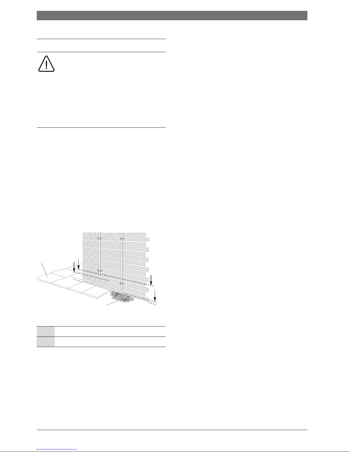
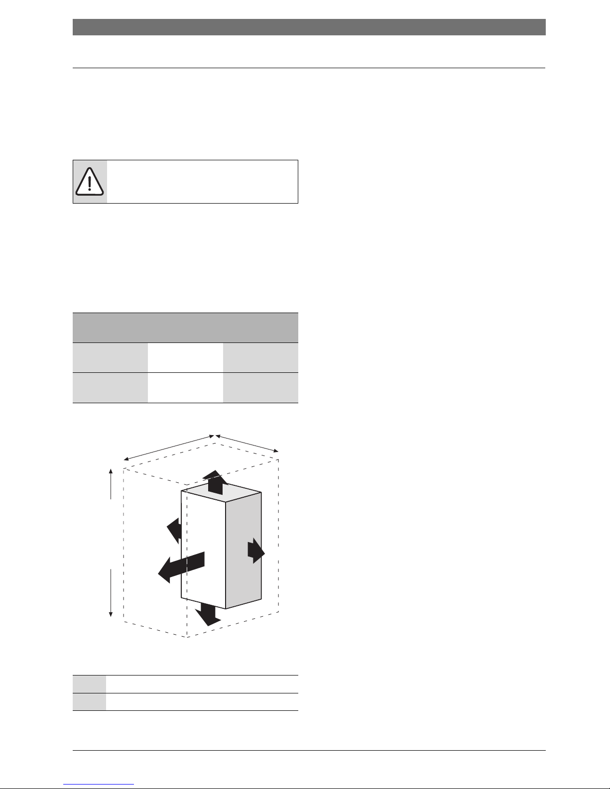
3.6.2 Servicing clearances ventilated compartment
Figure 15 shows the minimum space required to install
and service the boiler in a ventilated compartment.
• If a boiler is installed in a compartment with
clearances less than shown in the tables 14, 15, or 16
ventilation is required. Refer to table 11 for
ventilation requirements.
Fig. 15 Ventilated compartment
3.6.3 Compartments
• Minimum clearances must be maintained.
• An access door is required to install, service and
maintain the boiler and any ancillary equipment.
• If fitting the boiler into an airing cupboard use a noncombustible material to separate the boiler from the
airing space.
The material can be perforated up to a maximum hole
size of 13mm.
NOTE:
No surface protection is required against
heat transfer from the boiler
Vent position
To room or
internal space
Direct to
outside
High level Minimum free
area 122 cm
2
Minimum free
area 61 cm
2
Low level Minimum free
area 122 cm
2
Minimum free
area 61 cm
2
Tab. 11 Compartment ventilation
* Minimum clearance to removable door
** Minimum clearance required for servicing
Tab. 12 Minimum clearances
6720643895-121.1Wo
+ 30 mm
above elbow
930 mm 410 mm
25 mm*
600 mm**
5 mm
Using 100 mm
flue kit
1080 mm
Using 125 mm
flue kit
1100 mm
200 mm
5 mm
18 | Pre-installation AU/NZ
6 720 646 195a (2010/11)
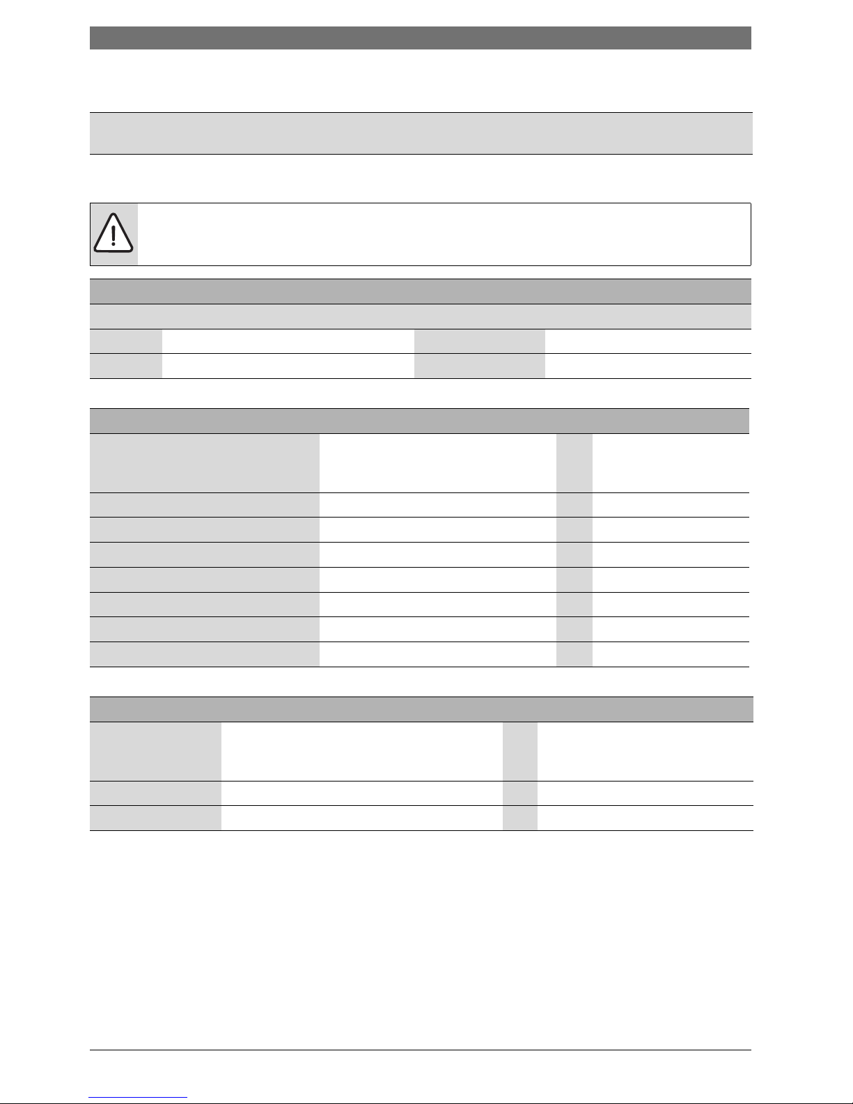
3.6.4 Boiler clearances - Unventilated compartments
3.6.5 Installation clearances - unventilated compartments
The tables below show the options for the minimum space required to install and service the boiler inside an
unventilated compartment.
Tab. 13
CAUTION: Clearances
B Top and bottom clearances must not be reduced below the values shown in table 14 as they are the
minimum clearances required for servicing.
Unventilated compartment installation clearances (millimetres)
The suggested total unventilated compartment minimum clearances are:
Side Above Below Front (to removable door)
400 170 approx. (30 above the elbow) 200 100
Tab. 14 Minimum unventilated compartment clearances
If side clearances are reduced (millimetres)
If total side clearance is reduced to:
(combined left and right clearances
excluding the boiler)
Increase height clearances to (approx):
(combined top and bottom clearances
excluding the boiler)
OR Front clearance (to
removable door) must
be increased to:
350 441 129
300 523 161
250 617 200
200 717 243
150 856 295
100 1012 358
50 1202 434
Tab. 15 Reduced side clearances
If front clearance is reduced (millimetres)
If front clearance (to
removable door) is
reduced to:
Increase overall height clearances to approx:
(combined top and bottom clearances
excluding the boiler)
OR Increase total side clearance to:
(combined left and right
clearances excluding the boiler)
50 511 505
25 596 569
Tab. 16 Reduced front clearances
Pre-installation | 19AU/NZ
6 720 646 195a (2010/11)
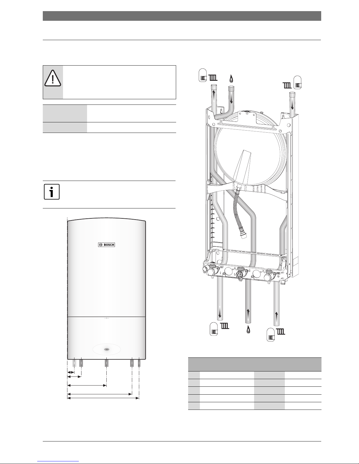
3.7 Plumbing manifold
3.7.1 Connections
Use the fittings supplied in the hardware literature pack.
• If the boiler pipes are to be run behind the boiler
ensure that the pipes pass through the slot in the
white cardboard guide. This is fitted to the frame.
Fig. 16 Pipe dimensions
Fig. 17 Plumbing manifold
WARNING: If fitting an optional integral
diverter valve.
B Refer to the “optional integral diverter
valve” installation instructions.
Heating System ¾ inch BSP thread compression
fittings
Gas ¾ inch BSP thread
Tab. 17
Further guidance on pipe routing can be
found printed on the boiler template
(supplied).
12345
6720646195-07.1Wo
# Function
From left
case edge
Øof pipe
connections
1CH flow 70 mm ¾ BSP
2Gas 200 mm ¾ BSP
3CH return 330 mm ¾ BSP
4Condensate 35 mm 22mm
5 Pressure relief valve 367 mm ½ BSP
Tab. 18 Key to figures 16 & 17
1
2
3
4
5
1
2
3
6720644743-10.1Wo
20 | Pre-installation AU/NZ
6 720 646 195a (2010/11)
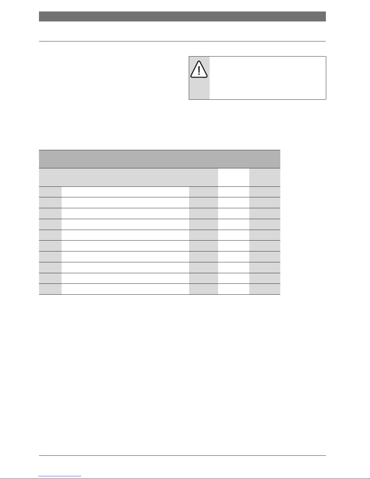
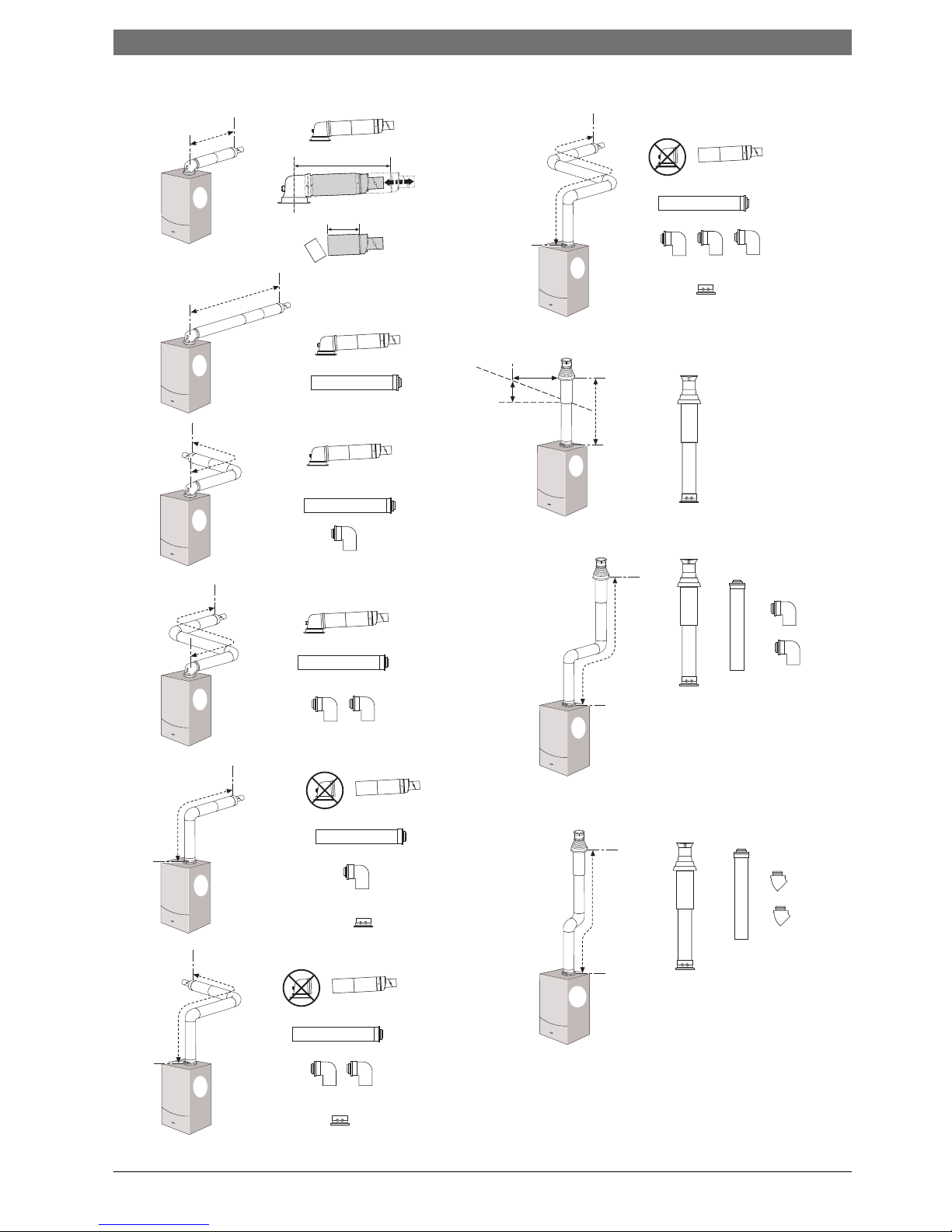
3.8 Flue options
The Condens 5000W series has the option of three
horizontal RSF (60/100 telescopic, 60/100 extended
telescopic and 80/125) flue systems and two vertical
RSF (60/100 or 80/125) flue systems:
The flue systems have different maximum flue lengths
The page opposite shows some possible flue
configurations.
Table 19 below shows the maximum straight length of
flue available to the installer after the effective lengths
of the bends have been taken into account from each
flue option on the page opposite.
NOTE: Effective flue lengths:
B each 90° bend used is equivalent to
2 metres of straight flue
B each 45° bend used is equivalent to
1 metre of straight flue
Maximum straight flue length
available (mm)
Flue type Boiler
i System
60/100 80/125
1 Telescopic horizontal flue assembly All 570 1,070
2 Horizontal flue extension All 4,600 13,000
3 Horizontal flue with 1 x 90° bend All 2,600 11,000
4 Horizontal flue with 2 x 90° bends All N/A 9,000
5 High level horizontal flue with 1 x 90° bend All 2,600 11,000
6 High level horizontal flue with 2 x 90° bends All N/A 9,000
7 High level horizontal flue with 3 x 90° bends All N/A 7,000
8 Vertical balanced flue assembly All 6,400 15,000
9 Vertical balanced flue with 2 x 90° bends All 2,400 11,000
10 Vertical balanced flue with 2 x 45° bends All 4,400 13,000
Tab. 19 Flue options
Pre-installation | 21AU/NZ
6 720 646 195a (2010/11)
350 mm - 570 mm
130 mm Min
Flat roof
300 mm
500 mm
Pitched
roof
2
3
4
5
6
10
9
8
7
1
6720643895-12.1Wo
 Loading...