

Page 1
Montage- und Gebrauchsanleitung | Installation and operating instructions | Notice de montage et d’utilisation |
Istruzioni per l‘uso e per il montaggio | Montage- en gebruikshandleiding | Упътване за монтаж и употреба
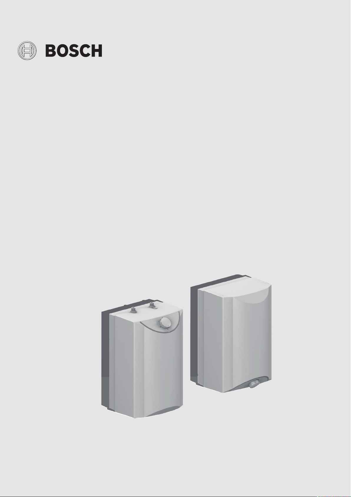
Tronic 2500 TO | Tronic 3500 TO | Tronic Store Advanced
TR2500TO 5 B | TR3500TO(R) 5 T
6 720 876 005 (2019/07) DIV
Page 2
Inhaltsverzeichnis
Inhaltsverzeichnis 1 Sicherheitshinweise
Dieses Gerät ist nur für den Hausgebrauch und ähnli-
1 Sicherheitshinweise . . . . . . . . . . . . . . . . . . . . . . . . . . . . . . . . . . 2
2 Montageanleitung . . . . . . . . . . . . . . . . . . . . . . . . . . . . . . . . . . . . 3
2.1 Auspacken . . . . . . . . . . . . . . . . . . . . . . . . . . . . . . . . . . . . 3
2.2 Produktbeschreibung . . . . . . . . . . . . . . . . . . . . . . . . . . . 3
2.3 Wandmontage . . . . . . . . . . . . . . . . . . . . . . . . . . . . . . . . . 3
2.4 Wasseranschluss . . . . . . . . . . . . . . . . . . . . . . . . . . . . . . . 3
2.5 Erstinbetriebnahme . . . . . . . . . . . . . . . . . . . . . . . . . . . . . 4
2.5.1 Elektroanschluss . . . . . . . . . . . . . . . . . . . . . . . . . . . . . . . 4
2.5.2 Heizvorgang überprüfen . . . . . . . . . . . . . . . . . . . . . . . . . 4
2.5.3 Wassertemperatur begrenzen. . . . . . . . . . . . . . . . . . . . . 4
3 Technische Daten. . . . . . . . . . . . . . . . . . . . . . . . . . . . . . . . . . . . . 4
4 Gebrauchsanleitung . . . . . . . . . . . . . . . . . . . . . . . . . . . . . . . . . . 5
4.1 Wassertemperatur einstellen . . . . . . . . . . . . . . . . . . . . . 5
4.2 Wassertemperatur begrenzen. . . . . . . . . . . . . . . . . . . . . 5
4.3 Ausschalten . . . . . . . . . . . . . . . . . . . . . . . . . . . . . . . . . . . 5
4.4 Nur Untertischgeräte TR3500TO 5 T und
TR3500TOR 5 T . . . . . . . . . . . . . . . . . . . . . . . . . . . . . . . . 5
4.5 Reinigung . . . . . . . . . . . . . . . . . . . . . . . . . . . . . . . . . . . . . 5
4.6 Entkalken . . . . . . . . . . . . . . . . . . . . . . . . . . . . . . . . . . . . . 5
4.7 Wartung . . . . . . . . . . . . . . . . . . . . . . . . . . . . . . . . . . . . . . 5
che Zwecke bestimmt.
• Das Gerät wie in Text und Bild beschrieben montieren und bedienen. Wir übernehmen keine Haftung
für Schäden, die durch Nichtbeachtung dieser Anleitung entstehen.
• Dieses Gerät ist für den Gebrauch bis zu einer Höhe
von 2 000 m über dem Meeresspiegel bestimmt.
• Das Gerät nur in einem frostfreien Raum installieren
und lagern (Restwasser).
• Das Gerät muss in trockenen und sauberen Räumen
installiert und betrieben werden.
WARNUNG:
Stromschlaggefahr!
Ziehen Sie im Fehlerfall sofort den Netzstecker!
Bei einer Undichtigkeit am Gerät sofort die Kaltwasser zuleitung schließen.
• Das Gerät nur von einem Fachmann anschließen
und in Betrieb nehmen lassen.
5 Eine Störung, was tun? . . . . . . . . . . . . . . . . . . . . . . . . . . . . . . . . 6
6 Kundendienst . . . . . . . . . . . . . . . . . . . . . . . . . . . . . . . . . . . . . . . . 6
7 Umweltschutz/Entsorgung. . . . . . . . . . . . . . . . . . . . . . . . . . . . . 6
• Um Gefährdungen zu vermeiden, dürfen Reparaturen und Wartung nur von einem Fachmann
durchgeführt werden.
• Vor der Montage die Wasserzuleitung absperren.
Netzstecker nicht einstecken.
VORSICHT:
Achtung!
Gerät erst vollständig mit Wasser füllen, dann Netz
stecker einstecken, sonst löst die wieder einschaltbare Sicherheitstemperaturbegrenzung aus.
• Die gesetzlichen Vorschriften sowie die Anschlussbedingungen des Elektrizitäts-Versorgungsunternehmens und des Wasserwerkes einhalten.
• Das Gerät nur an eine vorschriftsmäßig installierte
Schutzkontakt-Steckdose anschließen. Kein Verlängerungskabel verwenden.
• Vor dem Öffnen des Gerätes Netzstecker ziehen.
• Das Gerät darf nicht über eine externe Schaltvorrichtung, wie beispielsweise eine Zeitschaltuhr, versorgt werden, um eine Gefährdung durch ein
unbeabsichtigtes Rücksetzen des Schutztemperaturbegrenzers im Störfall zu vermeiden.
• Die Anschlussleitung darf nicht an heißen Teilen anliegen. Die Isolierung könnte beschädigt werden.
• Den Kleinspeicher nur offen (drucklos) und für
eine Zapfstelle verwenden. Der Warmwasser-
2
Tronic 2500 TO | Tronic 3500 TO | Tronic Store Advanced – 6 720 876 005 (2019/07)
Page 3

Montageanleitung
Auslauf dient zum Druckausgleich und darf nur
an die dafür geeignete Armatur angeschlossen
werden (Bestell-Nr. BZ 13051, BZ 13071 oder
BZ 13062 für Untertischgeräte oder BZ 11113
für Übertischgeräte).
• Der Auslauf der Armatur muss immer frei sein. Keine Perlatoren (Luftsprudler) oder Brausearmaturen
verwenden.
• Dieses Gerät kann von Kindern ab 8 Jahren und darüber sowie von Personen mit verringerten physischen, sensorischen oder mentalen Fähigkeiten
oder Mangel an Erfahrung und Wissen benutzt werden, wenn sie beaufsichtigt oder bezüglich des sicheren Gebrauchs des Gerätes unterwiesen
wurden und die daraus resultierenden Gefahren
verstehen. Kinder dürfen nicht mit dem Gerät spielen. Reinigung und Benutzer-Wartung dürfen nicht
von Kindern ohne Beaufsichtigung durchgeführt
werden.
• Kinder vom Gerät fern halten.
• Kinder beaufsichtigen, um zu verhindern, dass sie mit dem Gerät spielen.
• Das Warmwasserrohr kann heiß werden. Kinder darauf hinweisen.
• Keine Scheuermittel oder anlösende Reinigungsmittel verwenden.
• Keinen Dampfreiniger benutzen.
Die Montage- und Gebrauchsanleitung bitte sorgfältig durchlesen, danach handeln und aufbewahren!
2 Montageanleitung
2.1 Auspacken
• Das neue Gerät auf Transportschäden kontrollieren!
• Verpackung und gegebenenfalls Altgerät umweltgerecht entsorgen.
Lieferumfang (Bild 1)
1 Gerät mit Bedienblende
2 Montagebügel
3 Nur TR3500TOR 5 T:
Befestigung (2 Schrauben, 2 Dübel)
4 Schriftgut
Montagevorbereitung (Bild 1)
• Vor der Montage die Wasserzuleitung absperren. Netzstecker
nicht einstecken.
• Montagebügel am Gerät abnehmen und die Halteringe
abbrechen (A).
• Anschlusskabel je nach gewünschter Länge auf der Geräte-rückseite
fixieren (B).
2.3 Wandmontage
Untertischgeräte TR3500TO 5 T und TR3500TOR 5 T (Bild 2)
• Gerät auf der Wand ausrichten und an den drei Einkerbungen (oben,
links und rechts am Gerät) die Markierungen anzeichnen (A).
• Die Markierungen mit der Wasserwaage zu einem Linienkreuz verbinden (B1 und B2).
• Den Montagebügel an der Einkerbung oben am Kreuzungspunkt der
gezeichneten Linien ansetzen und die Löcher anzeichnen (C).
• Löcher bohren und Dübel einsetzen (D1).
• Den Montagebügel (Einkerbung oben) mit den Schrauben an der
Wand anbringen (D2).
• Gerät in den Montagebügel einhängen (D3).
Gerät tauschen (Bild 3)
Bei Austausch eines alten Kleinspeichers durch dieses neue Gerät kön-
nen die vorhandenen Befestigungslöcher mit Dübeln verwendet werden.
Es ist aber zu beachten, dass das neue Gerät etwa 2 cm höher ist.
Soll das neue Gerät oben bündig wie das alte Gerät sein (E1):
• Den neuen Montagebügel mit der Einkerbung nach oben an der Wand
anbringen.
Soll das neue Gerät unten bündig wie das alte Gerät sein (E2):
• Den neuen Montagebügel umdrehen und mit der Einkerbung nach
unten an der Wand anbringen.
Übertischgeräte TR2500TO 5 B (Bild 4)
• Gerät auf der Wand ausrichten und an den drei Einkerbungen
(oben, links und rechts am Gerät) die Markierungen anzeichnen (F).
• Die Markierungen mit der Wasserwaage zu einem Linienkreuz verbinden (G1 und G2).
• Den Montagebügel an der Einkerbung oben am Kreuzungspunkt
der gezeichneten Linien ansetzen und die Löcher anzeichnen (H).
• Löcher bohren und Dübel einsetzen (I1).
• Den Montagebügel (Einkerbung oben) mit den Schrauben an der
Wand anbringen (I2).
Gerät tauschen (Bild 5)
Bei Austausch eines alten Kleinspeicher durch dieses neue Gerät können
die vorhandenen Befestigungslöcher mit Dübeln verwendet werden. Es ist
aber zu beachten, dass das neue Gerät etwa 2 cm höher ist.
• Den neuen Montagebügel umdrehen und mit der Einkerbung nach
unten an der Wand anbringen (J).
2.4 Wasseranschluss
2.2 Produktbeschreibung
Der Kleinspeicher ist für den offenen (drucklosen) Anschluss geeignet.
Er erhitzt und speichert Trinkwasser bis ca. 85 °C. Mit dem Temperaturwähler können verschiedene Temperaturstufen eingestellt werden.
Das Gerät darf nicht mit vorgewärmtem Wasser betrieben werden, sonst
löst die Sicherheitstemperaturbegrenzung aus.
Das Gerät wird mit dem Netzstecker angeschlossen.
Diese Montage- und Gebrauchsanleitung beschreibt verschiedene Gerä-
tetypen:
• Untertischgeräte mit zusätzlicher Tropfstoppfunktion und Druck-
stopp TR3500TO 5 T und TR3500TOR 5 T
• Übertischgeräte TR2500TO 5 B
Tronic 2500 TO | Tronic 3500 TO | Tronic Store Advanced – 6 720 876 005 (2019/07)
VORSICHT:
Achtung!
Die vorhandene Armatur darf nicht verkalkt sein.
• Gewinde nicht fetten!
Info: Ersatz für beschädigte Gewindestutzen ist beim Kundendienst erhältlich.
Untertischgeräte TR3500TO 5 T und TR3500TOR 5 T (Bild 6)
• Bei Bedarf Armatur montieren (A1 und A2).
• Dichtung einsetzen (B1).
• Auf den axialen Sitz der Anschlussrohre in den Stutzen achten.
3
Page 4

Technische Daten
• Überwur fmutter gerade auf Gewinde aufsetzen und von Hand andrehen (B2).
• Verschraubungen festziehen (C). Gewindestutzen am Speicher mit
Schraubenschlüssel gegenhalten.
• Verschraubung nach einigen Aufheizvorgängen nachziehen.
Übertischgeräte TR2500TO 5 B (Bild 7)
• Bei Bedarf Mischbatterie montieren (D1 bis D3).
• Verbindungsrohre zur Mischbatterie mit Dichtung einsetzen (E).
Auf den axialen Sitz der Anschlussrohre in den Stutzen achten.
• Dichtungen am Verbindungsrohr einsetzen (F1).
• Gerät einhängen (G).
• Überwurfmutter (F2) gerade auf Gewinde aufsetzen und von Hand
andrehen.
• Verschraubungen festziehen (H1 und H2). Gewindestutzen am Speicher mit Schraubenschlüssel gegenhalten (H1).
2.5 Erstinbetriebnahme
Hinweis: Bei einem nicht mit Wasser gefüllten Gerät löst die wieder ein-
schaltbare Sicherheitstemperaturbegrenzung aus!
2.5.2 Heizvorgang überprüfen
• Drehwähler auf „3“ (ca. 85 °C) drehen.
• Aufheizen überwachen, bis die Kontrolllampe nach ca.
12‒18 Minuten erlischt.
• Temperatur prüfen.
VORSICHT:
Hat die Sicherheitstemperaturbegrenzung den Kleinspeicher abgeschaltet, Netzstecker ziehen, Warmwasserhahn öffnen und ca. 4 Liter Wasser
durchlaufen lassen, dann Netzstecker wieder einstecken.
Das Gerät ist nun wieder betriebsbereit
2.5.1 Elektroanschluss
• Wichtig: Netzstecker noch nicht einstecken!
• Gerät erst vollständig mit Wasser füllen, das Wasser muss aus der Armatur laufen.
• Danach Netzstecker einstecken.
2.5.3 Wassertemperatur begrenzen
Die Auslauftemperatur des Kleinspeichers kann mechanisch auf Stufe
„1“ (ca. 38 °C) oder Stufe „eco“ (ca. 60 °C) begrenzt werden (siehe
„Bedienung“, Seite 5).
Energiesparen
• Zum Energiesparen den Drehwähler auf „eco“ stellen.
• Bitte dem Benutzer die Montage- und Gebrauchsanleitung übergeben und das Gerät erklären.
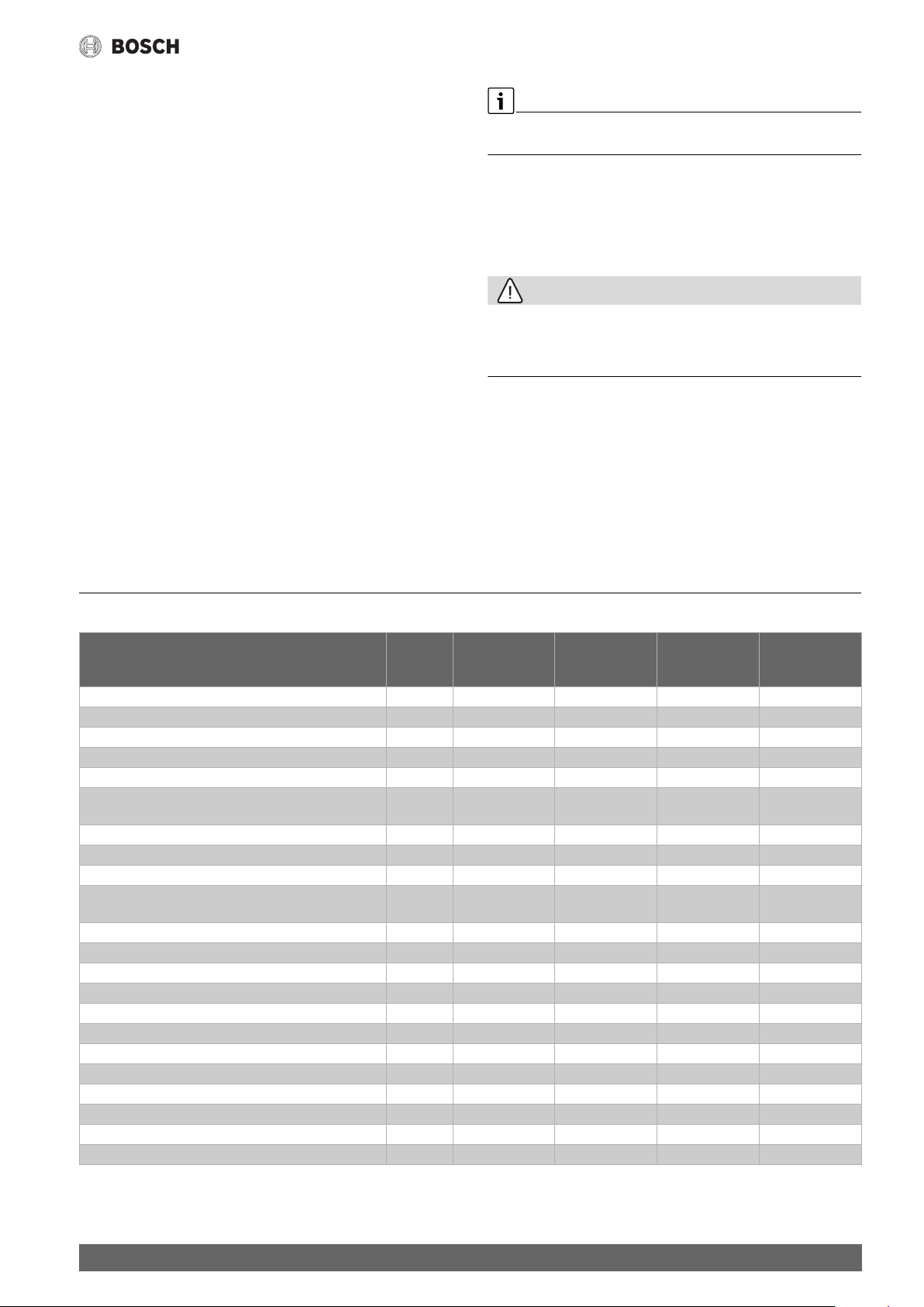
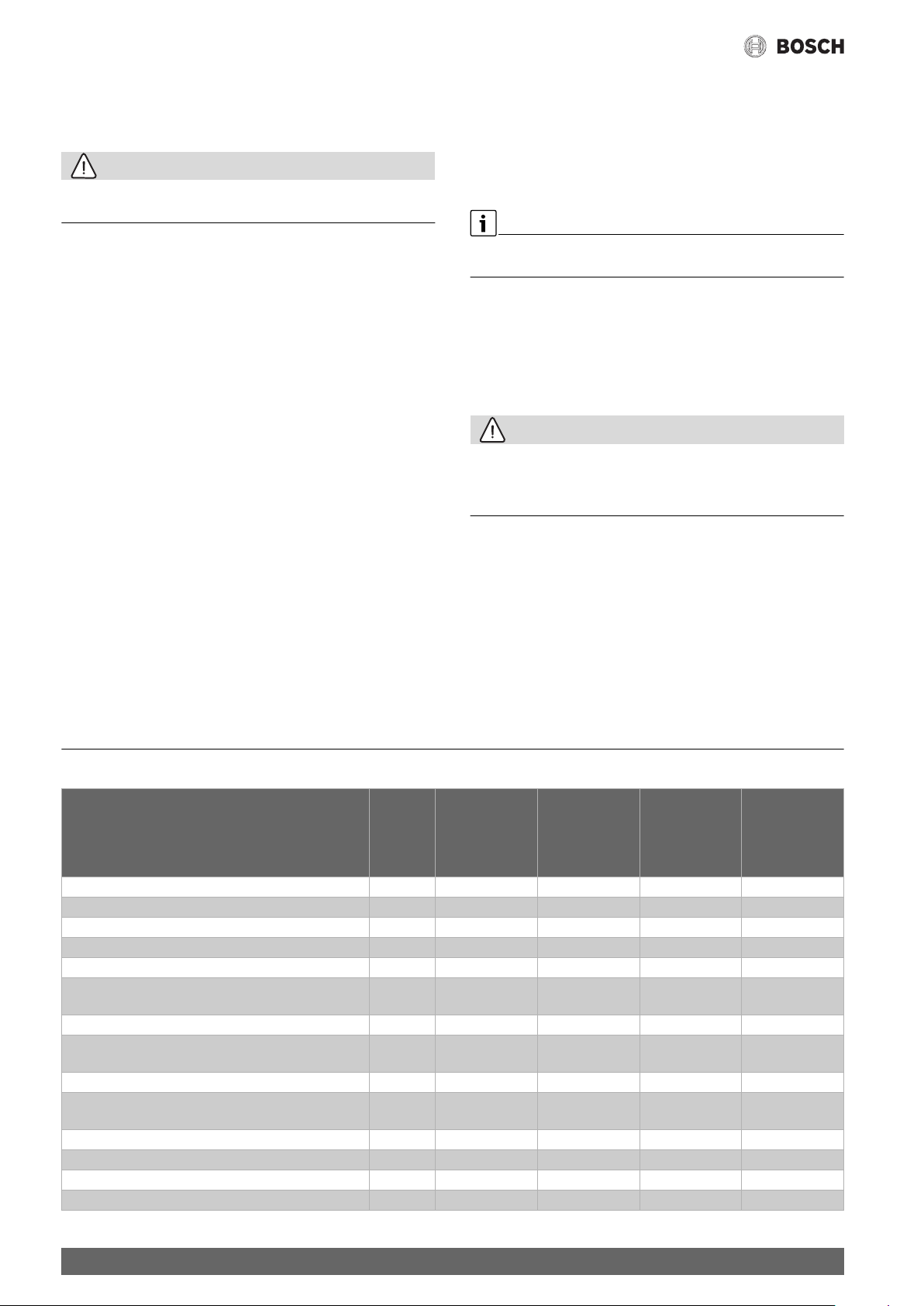
3 Technische Daten
Typ TR3500TO 5 T
Untertisch
Nennleistung [kW] 2,2 1,8 2,2 1,8
Nenninhalt [l] 5,0 5,0 5,0 5,0
CLICKFIX plus Montagetechnik
Druckstopp – –
Tropfstopp ––
Mischwassermenge 40 °C
(15 °C/65 °C) / (15 °C/85 °C)
Temperatur stufenlos einstellbar bis [°C] 85 85 85 85
Bereitschaftsenergieverbrauch bei 65 °C/24 h [kWh/d] 0,18 0,18 0,18 0,18
Elektroanschluss [V] 230 230 230 230
Aufheizzeit auf 60 °C
(Zulauftemperatur 12 °C)
Absicherung [A] 10 10 10 10
Wasseranschluss ["] 3/8 3/8 1/2 1/2
Maximaler Durchfluss [l/min] 5 5 5 5
Kabellänge [m] 0,6 0,6 0,6 0,6
Maße (Höhe×Breite×Tiefe) [mm] 435×270×240 435×270×240 435×270×240 435×270×240
Gewicht gefüllt [kg] 7,7 7,7 7,7 7,7
Energieeffizienzklasse AAAA
Lastprofil XXS XXS XXS XXS
Jahresenergieverbrauch [kWh] 515 484 508 531
Täglicher Stromverbrauch [kWh] 2,420 2,340 2,379 2,513
Schallleistungspegel [dB] 15 15 15 15
Warmwasserbereitungs-Energieeffizienz [%] 35,9 36,8 36,3 35,0
[l] 9,5/14 9,5/14 9,5/14 9,5/14
[min] 8 9 8 9
TR3500TOR 5 T
TR3500TO 5 T
Untertisch
TR2500TO 5 B
Übertisch
TR2500TO 5 B
Übertisch
4
Tronic 2500 TO | Tronic 3500 TO | Tronic Store Advanced – 6 720 876 005 (2019/07)
Page 5
4 Gebrauchsanleitung
• Vor dem Gebrauch des Gerätes, bitte sorgfältig diese Anleitung
durchlesen und beachten!
• Wichtig: Das Gerät niemals Frost aussetzen!
WARNUNG:
Stromschlaggefahr!
Ziehen Sie im Fehlerfall sofort den Netzstecker!
Bei einer Undichtigkeit am Gerät sofort die Kaltwasserzuleitung
schließen.
Bitte die ausführlichen Sicherheitshinweise am Anfang dieser Anleitung durchlesen und beachten!
Bedienung (Bild 8)
Der Kleinspeicher erhitzt und speichert Trinkwasser bis ca. 85 °C.
Gebrauchsanleitung
Die Druckabschaltung verriegelt automatisch den Wasserzulauf und verhindert ein Platzen des Behälters.
Hat der Druckstopp ausgelöst, erscheint oben am Gerät ein roter Stift (C1).
• Unbedingt die Störung beheben (siehe Kapitel 5„Eine Störung, was
tun?“).
• Erst nach Behebung der Störung lässt sich der rote Stift wieder leicht
eindrücken (C2). Der Wasserzulauf ist wieder frei.
• Bei wiederholtem Auslösen den Kundendienst benachrichtigen.
Wichtig: Ausfahrweg des Stifts (C1) nicht durch Gegen-stände
versperren.
4.5 Reinigung
Keine Scheuermittel oder anlösende Reinigungsmittel verwenden.
Keinen Dampfreiniger benutzen.
• Gerät außen mit einem milden Reinigungsmittel abwischen.
• Sieb im Strahlregler von Schmutz- und Kalkablagerungen reinigen.
4.1 Wassertemperatur einstellen
• Die gewünschte Auslauftemperatur stufenlos mit dem Drehwähler
von 35 °C bis 85 °C einstellen.
oder
• Die gewünschte Auslauftemperatur fest einstellen (A):
Frostschutz
1 ca. 38 °C (leichte Rastung)
eco Energie sparen ca. 60 °C (leichte Rastung)
3 Heißwasser ca. 85 °C
Beim Aufheizen leuchtet die Kontrolllampe.
Bei Übertischgeräten tropft etwas Ausdehnungswasser aus dem Auslauf.
Bei hohen Temperaturen verkalkt das Gerät schneller.
Tipp: Um das Gerät ökonomisch zu betreiben und die Verkalkung zu reduzieren, den Drehwähler auf „eco“ stellen.
Hinweis: Wenn das Gerät längere Zeit nicht benutzt wurde, z. B. während des Urlaubs, das Wasser auf Stufe „3“ kurz auf heizen lassen.
4.2 Wassertemperatur begrenzen
Um Verbrühungen durch heißes Wasser zu vermeiden, Auslauftemperatur begrenzen:
• Drehwähler auf „●“ stellen.
• Abdeckung des Drehwählers aufklappen.
• Zwischen „1“ = ca. 38 °C (B2) oder „eco“ = ca. 60 °C (B1) wählen.
• Abdeckung schließen.
4.6 Entkalken
• Auslaufrohr mit handelsüblichen Entkalkern oder Essig entkalken.
• Bei Entkalkern die Warnhinweise des Herstellers beachten.
Wenn bei voll geöffneter Armatur das Wasser deutlich langsamer ausläuft,
Kleinspeicher und Armatur von einem Fachmann entkalken lassen. Andernfalls kann der Druckstopp wegen unzulässig hohen Drucks auslösen.
4.7 Wartung
Um Gefährdungen zu vermeiden, dürfen folgende Reparaturen und Wartungsarbeiten nur von einem von uns konzessionierten Kundendienst
durchgeführt werden.
• Bei allen Arbeiten das Gerät vom elektrischen Netz trennen und den
Wasserzulauf absperren.
Elektrische Anschlussleitung wechseln
Bei sichtbaren Schäden am elektrischen Kabel:
• Gerät ausschalten, Netzstecker ziehen und Kundendienst benachrichtigen.
Zulaufsieb reinigen (Bild 10)
Bei zu geringem Durchfluss von Wasser und entkalktem Sieb im Wasserhahn:
• Kundendienst benachrichtigen und Zulaufsieb (D) reinigen lassen.
Schutzleiterprüfung (Bild 11)
Bei gewerblich genutzten Geräten einmal im Jahr die elektrische Sicherheit durch eine Elektro-Fachkraft nach DGUV Vorschrift 3 prüfen lassen:
• Gerät ausschalten und Netzstecker ziehen.
• Schutzleiterprüfung am Erdungskontakt (E) durchführen.
4.3 Ausschalten
Drehwähler auf „●“ stellen (A). Die Heizung ist ausgeschaltet.
4.4 Nur Untertischgeräte TR3500TO 5 T und TR3500TOR 5 T
Tropfstopp
Die Tropfstoppfunktion verhindert, dass beim Aufheizen Ausdehnungswasser aus dem Wasserhahn tropft. Wird Wasser erhitzt, treten darin gelöste Gase (Luft) aus dem Wasser aus. Je nach Menge der austretenden
Gase kann daher – wenn eine hohe Temperatur eingestellt ist – Restwasser aus dem Armaturenauslauf gedrückt werden.
Druckstopp (Bild 9)
Das Gerät verfügt über eine Druckabschaltung. Die Druckabschaltung
zeigt an, wenn die Armatur verkalkt ist (geringer oder kein Abfluss).
Sie erkennt ab einem Wasserdruck über 0,25 Mpa (2,5 bar) auch, wenn
das Gerät bei der Erstinstallation wasserseitig falsch installiert wurde.
Tronic 2500 TO | Tronic 3500 TO | Tronic Store Advanced – 6 720 876 005 (2019/07)
5
Page 6
Eine Störung, was tun?
5 Eine Störung, was tun?
Funktioniert Ihr Gerät nicht wie gewünscht, so liegt es oft nur an einer
Kleinigkeit. Bitte prüfen Sie, ob aufgrund folgender Hinweise die Störung
selbst behoben werden kann. Sie vermeiden dadurch die Kosten für einen unnötigen Kundendiensteinsatz.
• Bei allen Arbeiten das Gerät vom elektrischen Netz trennen und den
Wasserzulauf absperren.
Störung Ursache Behebung Wer
Das Gerät startet (heizt) nicht,
es fließt nur kaltes Wasser
Zu geringer Durchfluss von Wasser Das Sieb im Wasserhahn ist verstopft. Das Sieb entnehmen und reinigen oder entkalken. Kunde
Die Armatur tropft beim Aufheizen
trotz Tropfstopp.
Der Druckstopp hat ausgelöst,
es fließt kein Wasser mehr.
Konnte die Störung nicht behoben werden, bitte den Kundendienst anrufen.
Die Sicherung in der Hausinstallation hat
ausgelöst.
Der Netzstecker ist nicht eingesteckt. Netzstecker einstecken. Kunde
Die Sicherheitstemperaturbegrenzung hat
geschaltet.
Das Sieb im Kaltwasserzulauf ist verstopft. Zulaufsieb ausbauen, reinigen und wieder einbauen.
Der Wasserauslauf oder die Armatur ist verkalkt.
Häufiges, kurzzeitiges Zapfen oder Zapfen
bei geringem Warmwasserdurchfluss.
Die Tropfstopp-Funktion ist defekt. Gerät austauschen. Fachmann
Das Gerät wurde am Wasseranschluss falsch
installiert.
Die Armatur ist verkalkt. Armatur entkalken, den roten Stift des Druckstopps
Der Warmwasseransc hluss-Stutzen ist verstopft.
Die Sicherung in der Hausinstallation prüfen. Kunde
Netzstecker ziehen, Warmwasserhahn öffnen und ca.
4 Liter Wasser durchlaufen lassen. Netzstecker einstecken.
Gerät spülen. Falls nötig, diese Prozedur so lange
wiederholen, bis keine Partikel mehr im Sieb vorhanden sind.
Entkalken oder neue Armatur einbauen. Fachmann
Länger zapfen, Warmwasserdurchfluss erhöhen. Kunde
Gerät richtig anschließen, den roten Stift des Druckstopps hineindrücken.
hineindrücken.
Warmwasseranschluss- Stutzen reinigen, falls nötig
den Wasseranschluss tauschen. Anschließend den
roten Stift des Druckstopps hineindrücken.
Kunde
Fachmann
Fachmann
Kunde
Fachmann
6 Kundendienst
Wenn Sie den Kundendienst anfordern, geben Sie bitte die E-Nr. und die
FD-Nr. Ihres Gerätes an. Sie finden die Nummern im Bereich der beiden
Wasseranschlussstutzen des Kleinspeichers.
7 Umweltschutz/Entsorgung
Der Umweltschutz ist ein Unternehmensgrundsatz der Bosch-Gruppe.
Qualität der Produkte, Wirtschaftlichkeit und Umweltschutz sind für uns
gleichrangige Ziele. Gesetze und Vorschriften zum Umweltschutz
werden strikt eingehalten.
Zum Schutz der Umwelt setzen wir unter Berücksichtigung wirtschaftlicher Gesichtspunkte bestmögliche Technik und Materialien ein.
Verpackung
Bei der Verpackung sind wir an den länderspezifischen Verwertungssystemen beteiligt, die ein optimales Recycling gewährleisten.
Alle verwendeten Verpackungsmaterialien sind umweltverträglich und
wiederverwertbar.
Altgerät
Altgeräte enthalten Wertstoffe, die wiederverwertet werden können.
Die Baugruppen sind leicht zu trennen. Kunststoffe sind gekennzeichnet.
Somit können die verschiedenen Baugruppen sortiert und wiederverwertet oder entsorgt werden.
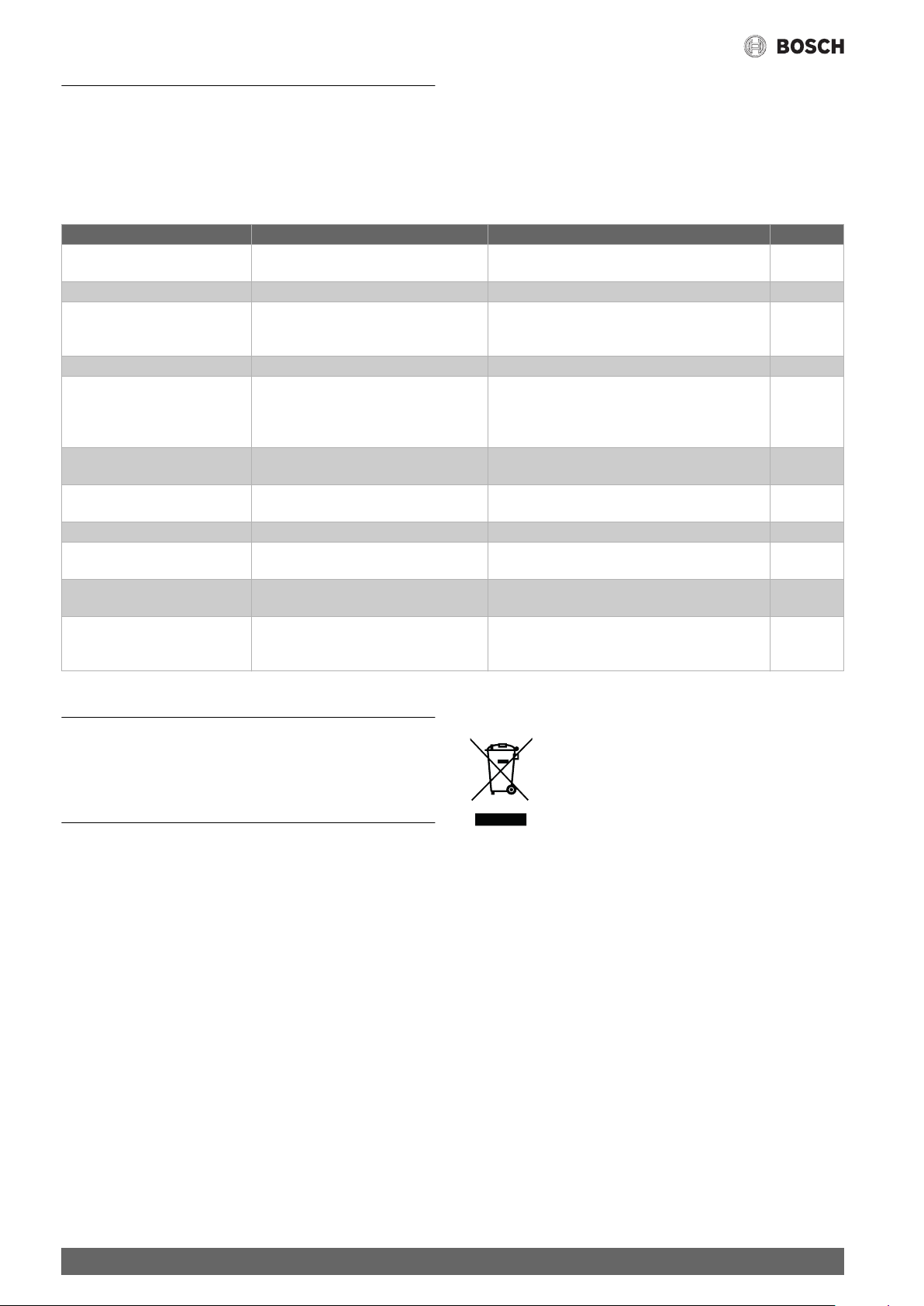
Elektro- und Elektronik-Altgeräte
Nicht mehr gebrauchsfähige Elektro- oder Elektronikgeräte müssen getrennt gesammelt und einer umweltgerechten Verwertung zugeführt werden (Europäische Richtlinie
über Elektro- und Elektronik-Altgeräte).
Nutzen Sie zur Entsorgung von Elektro- oder ElektronikAltgeräten die länderspezifischen Rückgabe- und Sam-
melsysteme.
Änderungen vorbehalten.
6
Tronic 2500 TO | Tronic 3500 TO | Tronic Store Advanced – 6 720 876 005 (2019/07)
Page 7

Table of Contents 1 Safety information
This appliance is intended for domestic use and the
1 Safety information . . . . . . . . . . . . . . . . . . . . . . . . . . . . . . . . . . . . 7
2 Installation instructions . . . . . . . . . . . . . . . . . . . . . . . . . . . . . . . 8
2.1 Unpacking . . . . . . . . . . . . . . . . . . . . . . . . . . . . . . . . . . . . . 8
2.2 Product description . . . . . . . . . . . . . . . . . . . . . . . . . . . . . 8
2.3 Wall mounting . . . . . . . . . . . . . . . . . . . . . . . . . . . . . . . . . . 8
2.4 Water connection . . . . . . . . . . . . . . . . . . . . . . . . . . . . . . . 8
2.5 First start-up . . . . . . . . . . . . . . . . . . . . . . . . . . . . . . . . . . . 9
2.5.1 Electrical connection . . . . . . . . . . . . . . . . . . . . . . . . . . . . 9
2.5.2 Checking the heating . . . . . . . . . . . . . . . . . . . . . . . . . . . . 9
2.5.3 Limitation of the water temperature . . . . . . . . . . . . . . . . 9
3 Technical data . . . . . . . . . . . . . . . . . . . . . . . . . . . . . . . . . . . . . . . . 9
4 Operating instructions. . . . . . . . . . . . . . . . . . . . . . . . . . . . . . . .10
4.1 Setting the water temperature . . . . . . . . . . . . . . . . . . . .10
4.2 Limitation of the water temperature . . . . . . . . . . . . . . .10
4.3 Switching off. . . . . . . . . . . . . . . . . . . . . . . . . . . . . . . . . .10
4.4 Undersink appliances only TR3500TO 5 T and
TR3500TOR 5 T . . . . . . . . . . . . . . . . . . . . . . . . . . . . . . .10
4.5 Cleaning . . . . . . . . . . . . . . . . . . . . . . . . . . . . . . . . . . . . .10
4.6 Descaling. . . . . . . . . . . . . . . . . . . . . . . . . . . . . . . . . . . . .10
4.7 Maintenance . . . . . . . . . . . . . . . . . . . . . . . . . . . . . . . . . .10
household environment only.
• Install and operate the appliance as described in
the text and illustrations. We do not accept liability
for damage resulting from failure to heed these
instructions.
• This appliance is intended for use up to an altitude
of 2000 m above sea level.
• The appliance may only be installed and stored in a
frost-free room (due to residual water).
• Install and operate this appliance only in dry and
clean areas.
WARNING:
Risk of electric shock!
If an fault occurs, immediately disconnect the plug
from the power supply!
Immediately shut off the cold water supply to the
appliance should it leak.
• The appliance may only be connected and put
5 A fault, what to do?. . . . . . . . . . . . . . . . . . . . . . . . . . . . . . . . . . .11
6 Customer Service . . . . . . . . . . . . . . . . . . . . . . . . . . . . . . . . . . . .11
7 Environmental protection/disposal. . . . . . . . . . . . . . . . . . . . .11
8 Guarantee . . . . . . . . . . . . . . . . . . . . . . . . . . . . . . . . . . . . . . . . . .11
into operation by qualified professional.
• To avoid potential sources of danger, repairs and
maintenance may only be undertaken by a
suitably qualified specialist.
• Shut off the water supply before connecting the
appliance. Do not insert the plug into the mains
socket.
Table of Contents
CAUTION:
Caution!
Fill the appliance with water first, then insert the
mains plug, otherwise the resettable safety
temperature limitation will trip.
• Observe the statutory regulations as well as the
connection regulations of the electrical and water
utility companies.
• Only connect the appliance to a correctly earthed
electrical socket. Do not use extension cables.
• Disconnect the power supply before opening the
appliance.
• The appliance may not be powered via an external
switching device such as a timer switch in order to
exclude the danger of an unintentional reset of the
safety temperature limitation in the event of a fault.
• The connection cable may not make contact with
hot components. This can damage the insulation.
Tronic 2500 TO | Tronic 3500 TO | Tronic Store Advanced – 6 720 876 005 (2019/07)
7
Page 8
Installation instructions
• The small water heater is only suitable for use
with an open (unpressurised) and a single tap
connection. The warm water outlet is used for
pressure compensation and may only be
connected to suitable fittings (Order
No. BZ 13051, BZ 13071 or BZ 13062 for
undersink appliances or BZ 11113 for oversink
appliances).
• The tap outlet must always remain free. Do not use
perlators (diffusers) or shower taps.
• This appliance can be used by children aged
8 years and older as well as by persons with
diminished bodily, sensory or mental perception, or
those who lack knowledge or experience, if they are
monitored or have received instruction concerning
use and comprehend the possible dangers that can
result. Children may not play with the appliance.
Cleaning and maintenance by the user may not be
performed by unsupervised children.
• Keep children away from the appliance.
• Please monitor children to ensure that they do not
play with the appliance.
• The warm water pipe may be hot. Please inform and
instruct children appropriately.
• Do not use aggressive or abrasive cleaning
detergents!
• Do not use a steam cleaner.
Please read this installation and operating
instruction manual carefully, then act accordingly!
Store for future reference.
2 Installation instructions
2.1 Unpacking
• Inspect the new appliance for transport damage!
• Please dispose of the packaging, and if applicable, the old appliance
in an environmentally-friendly manner.
Scope of delivery (Fig. 1)
1 Appliance with operating panel
2 Installation bracket
3 TR3500TOR 5 T only:
Mounting (2 screws, 2 wall plugs)
4 Documentation
2.2 Product description
The small water heater is only suitable for open (unpressurised)
installation. It heats and stores drinking water up to approx. 85 °C.
Different temperature levels can be selected with the temperature
selector knob.
The appliance may not be operated with pre-heated water, as otherwise
the safety temperature limitation will trip.
The appliance is connected using the mains plug.
This installation and operating instruction manual describes various
appliance types:
• Undersink appliances with additional drip stop function and
pressure stop TR3500TO 5 T and TR3500TOR 5 T
• Oversink appliances TR2500TO 5 B
Preparations for installation (Fig. 1)
• Shut off the water supply before connecting the appliance.
Do not insert the mains plug.
• Remove the installation bracket on the appliance and break off the
retaining rings (A).
• Fix the connection cable to the rear of the appliance to suit the
required length (B).
2.3 Wall mounting
Undersink appliances TR3500TOR 5 T and TR3500TO 5 T
(Fig. 2)
• Align the appliance on the wall and use the three indents (top, left and
right on the appliance) to apply markings (A).
• Connect the markings by a pattern of crossed lines with a spirit level
(B1 and B2).
• Place the installation bracket on top at the point of intersection of the
drawn lines and mark the position for the holes (C).
• Drill the holes and insert wall plugs (D1).
• Attach the installation bracket (notch at top) to the wall using the
screws (D2).
• Suspend the appliance in the installation bracket (D3).
Exchanging appliances (Fig. 3)
• When replacing an old small water heater with this new appliance, the
existing drill holes with wall plugs can be used. Please note that the
new appliance is approx. 2 cm higher.
If the new appliance is to be flush at the top like the old appliance (E1):
• Attach the new installation bracket to the wall with the notches at
the top.
If the new appliance is to be flush at the bottom like the old
appliance (E2):
• Turn the installation bracket around and attach to the wall with
the notches at the bottom.
Oversink appliances TR2500TO 5 B (Fig. 4)
• Align the appliance on the wall and use the three indents (top, left and
right on the appliance) to apply markings (F).
• Connect the markings to a pattern of crossed lines with a spirit level
(G1 and G2).
• Place the installation bracket on top at the point of intersection of the
drawn lines and mark the position for the holes (H).
• Drill the holes and insert wall plugs (I1).
• Attach the installation bracket (notch at top) to the wall using the
screws (I2).
Exchanging appliances (Fig. 5)
When replacing an old small water heater with this new appliance, the ex-
isting drill holes with wall plugs can be used. Please note that the new appliance is approx. 2 cm higher.
• Turn the installation bracket around and attach to the wall with the
notches at the bottom (J).
2.4 Water connection
CAUTION:
Caution!
The existing fitting may not be covered with scaling.
• Do not grease the thread!
Info: Replacement for damaged threaded nozzles available from
customer service.
8
Tronic 2500 TO | Tronic 3500 TO | Tronic Store Advanced – 6 720 876 005 (2019/07)
Page 9
Undersink appliances TR3500TO 5 T and TR3500TOR 5 T
(Fig. 6)
• Fit the taps if required (A1 and A2).
• Insert the seals (B1).
• Ensure the axial fit of the connection pipes in the nozzles.
• Place the union nuts on the thread and tighten them by hand (B2).
• Tighten the screw fitting (C). Counter the threaded nozzles on the
warm water heater with a wrench
• After the unit has been used to heat water a few times, retighten the
screw fitting.
Oversink appliances TR2500TO 5 B (Fig. 7)
• Install the mixer if required (D1 to D3).
• Insert the pipe connections to the mixer with seals (E). Ensure the
axial fit of the connection pipes in the nozzles.
• Insert the seals on the pipe connection (F1).
• Suspend the appliance (G).
• Place the union nut (F2) on the thread and tighten it by hand.
• Tighten the screw fittings (H1 and H2). Counter the threaded nozzles
on the warm water heater with a wrench (H1).
2.5 First start-up
2.5.1 Electrical connection
• Important: Do not insert the plug into the mains socket yet.
• Fill the appliance with water first. Water must flow from the fitting.
• Only then insert the plug into the mains socket.
Technical data
Note: If the appliance is not filled with water, the resettable safety
temperature limitation will trip!
2.5.2 Checking the heating
• Turn the rotary selector switch to “3” (approx. 85 °C).
• Monitor the heating process until the pilot lamp switches off after
approx. 12–18 minutes.
• Check the temperature.
CAUTION:
If the safety temperature limitation has switched off the small water
heater, unplug the mains plug, open the warm water tap and allow
approx. 4 litres of water to flow. Then plug the mains plug back in.
The appliance is ready again for operation.
2.5.3 Limitation of the water temperature
The temperature of the water leaving the tap for the small water heater
can be mechanically set to stage “1” (approx. 38 °C) or stage “eco”
(approx. 60 °C) (see “Operation”, page 10).
Conserving energy
• Set the rotary selector to “eco” to conserve energy.
• Hand over the installation and operating instructions to the user and
explain how the appliance operates.
3 Technical data
Type TR3500TO 5 T
Undersink
Rated output [kW] 2.2 1.8 2.2 1.8
Rated capacity [l] 5.0 5.0 5.0 5.0
CLICKFIX plus installation technology
Pressure stop – –
Drip stop ––
Mixed water quantities 40 °C
(15 °C/85 °C) / (15 °C/85 °C)
Variable temperature adjustment up to [°C] 85 85 85 85
Stand-by power consumption at 65 °C/24 h [kWh/d] 0.18 0.18 0.18 0.18
Electrical connection [V] 230 230 230 230
Heat-up time to 60 °C
( temperature 12 °C)
Fuse protection [A] 10 10 10 10
Water connection ["] 3/8 3/8 1/2 1/2
Maximum flow [l/min] 5 5 5 5
Cable length [m] 0.6 0.6 0.6 0.6
Dimensions (Height×Width×Depth) [mm] 435×270×240 435×270×240 435×270×240 435×270×240
Weight, filled [kg] 7.7 7.7 7.7 7.7
Energy efficiency class AAAA
Load profile XXS XXS XXS XXS
Annual energy consumption [kWh] 515 484 508 531
Daily energy consumption [kWh] 2,420 2,340 2,379 2,513
Sound power level [dB] 15 15 15 15
Hot water heating energy efficiency [%] 35,9 36,8 36,3 35,0
[l] 9.5/14 9.5/14 9.5/14 9.5/14
[min] 8 9 8 9
TR3500TOR 5 T
TR3500TO 5 T
Undersink
TR2500TO 5 B
Over-sink
TR2500TO 5 B
Over-sink
Tronic 2500 TO | Tronic 3500 TO | Tronic Store Advanced – 6 720 876 005 (2019/07)
9
Page 10
Operating instructions
4 Operating instructions
• Before using the appliance, please read the instructions
carefully and observe them!
• Important: The appliance may never be exposed to frost!
WARNING:
Risk of electric shock!
If a fault occurs, immediately disconnect the plug from the power
supply!
Immediately shut off the cold water supply to the appliance should
it leak.
Please read and observe the detailed safety instructions at the start
of these instructions!
Operation (Fig. 8)
The small water heater heats and stores drinking water up to approx. 85 °C.
water pressure exceeds 0.25 Mpa (2.5 bar) it even detects if the
appliance has been incorrectly connected with the water line during
initial installation. The pressure switch off automatically shuts off the
water inlet and prevents rupturing of the tank.
It the pressure stop has tripped, a red pin will appear at the top of the
appliance (C1).
• The fault must be corrected (see chapter 5 “A fault, what to do?”).
• After the fault has been corrected, the red pin can be pushed back in
easily (C2). The water inlet is now free.
• Please contact customer service if this occurs repeatedly.
Important: Do not block the path of the pin (C1) with objects.
4.5 Cleaning
Do not use aggressive or abrasive cleaning detergents!
Do not use a steam cleaner.
• Clean appliance externally with a mild cleaning agent.
• Clean the dirt and lime scale deposits in the aerator filter.
4.1 Setting the water temperature
• The required outlet temperature from 35 °C to 85 °C can be set with
the rotary selector switch.
or:
• Set the required fixed outlet temperature (A):
Frost protection
1 Approx. 38 °C (soft lock-in)
eco Conserve energy approx. 60 °C (soft lock-in)
3 Hot water approx. 85 °C
The pilot lamp lights up during heat up.
Water drips out of the tap with oversink appliances.
The appliance with be covered more quickly with limescale at higher
temperatures.
Tip: Set the rotary selector switch to “eco” to operate the appliance
economically and to reduce the effects of limescale.
Note: If the appliance has not been used for an extended period,
e. g. during a holiday, allow the water to briefly heat up to stage “3”.
4.2 Limitation of the water temperature
Limit the outlet temperature to avoid scalding with hot water:
• Set the rotary selector switch to “●”.
• Open the cover of the rotary selector switch.
• Select between “1” = approx. 38 °C (B2) or “eco” =
approx. 60 °C (B1).
• Close the cover.
4.6 Descaling
• Descale the outlet pipe with commercially available descaling agent
or vinegar.
• Please observe the manufacturers warnings when descaling.
If the water flows significantly slower when the tap is fully opened, the
small water heater and tap should be descaled by a specialist. Otherwise,
the pressure stop may trip due to an unpermissible high pressure.
4.7 Maintenance
The following repairs and maintenance may only be carried out by an
authorised customer service representative to avoid potential sources
of danger.
• The electrical mains supply and the water supply must be shut off
before all work on the appliance.
Exchange of the electrical connection cable
When the electrical cable is visibly damaged:
• Switch off the device, unplug the mains plug and contact customer
service.
Cleaning the inlet filter (Fig. 10)
When the flow of water is too low and the inlet filter in the tap is descaled:
• Contact customer service and get the inlet filter (D) cleaned.
4.3 Switching off
Set the rotary selector switch to “●” (A). The heating is switched off.
4.4 Undersink appliances only TR3500TO 5 T and TR3500TOR 5 T
Drip stop
The drip stop function prevents expanding water from dripping from the
tap during heat up. If water is heated, the gasses (air) dissolved in it will
be released by the water.
Depending on the quantity of gas released – particularly when a higher
temperature is selected – it can force residual water from the tap.
Pressure stop (Fig. 9)
The appliance features pressure switch off. The pressure switch off
indicates when the tap is clogged by limescale (low or no flow). When
10
Tronic 2500 TO | Tronic 3500 TO | Tronic Store Advanced – 6 720 876 005 (2019/07)
Page 11
A fault, what to do?
5 A fault, what to do?
If your appliance does not operate as required, it is often due to a very
minor problem. Please check whether you can remedy the fault yourself
by using the following guidelines. You will save yourself the costs of an
unnecessary visit by customer service personnel.
• The electrical mains supply and the water supply must be shut off
before all work on the appliance.
Fault Cause Solution Who
The appliance does not start
(heat), only cold water flows.
Water flow-rate is too low. The filter in the tap is clogged. Remove the filter and either clean it or descale it. Customer
The tap drips during heat up
regardless of the drip stop.
The pressure stop has tripped,
water no longer flows.
If the fault could not be eliminated, please call customer service.
The fuse in the house electrical installation
has tripped/blown.
The mains plug is not inserted. Insert the plug into the mains socket. Customer
The safety temperature limitation has
tripped.
The filter in the cold water regulating valve is
clogged.
The water outlet or the tap is clogged by
limescale.
Frequent, momentary dispensing or
dispensing with a low water flow.
The drip stop function is defective. Exchange the appliance. Servicing
The appliance has been incorrectly installed
on the water connection.
The fitting is clogged by limescale. Descale the tap, push in the red pin of the pressure
The warm water connection nozzle is
clogged.
Check the fuse in the house electrical installation. Customer
Unplug the mains plug, open the warm water tap and
allow approx. 4 litres of water to flow. Insert the plug
into the mains socket.
Remove, clean and reinstall the inlet filter. Circulate
water through the appliance.
If necessary, repeat this procedure until the filter is
free of particles.
Descale or install a new fitting. Servicing
Longer dispensing, increase the flow of warm water. Customer
Connect the appliance correctly, push in the red pin
of the pressure stop.
stop.
Clean the warm water connection nozzle and
exchange the water connection if necessary. Then
push in the red pin of the pressure stop.
Customer
Servicing
expert
expert
expert
Servicing
expert
Customer
Servicing
expert
6 Customer Service
We ask you to always provide the E-No. and the FD-No. of your appliance
when calling in a customer service engineer. You will find the number
near both water connection nozzles of the small water heater.
7 Environmental protection/disposal
Environmental protection is a fundamental corporate strategy of the
Bosch Group.
The quality of our products, their economy and environmental safety are
all of equal importance to us and all environmental protection legislation
and regulations are strictly observed.
We use the best possible technology and materials for protecting the
environment taking account of economic considerations.
Packaging
Where packaging is concerned, we participate in country-specific
recycling processes that ensure optimum recycling.
All of our packaging materials are environmentally compatible and can be
recycled.
Used appliances
Used appliances contain valuable materials that can be recycled.
The various assemblies can be easily dismantled. Synthetic materials are
marked accordingly. Assemblies can therefore be sorted by composition
and passed on for recycling or disposal.
Used electrical and electronic appliances
Electrical or electronic devices that are no longer
serviceable must be collected separately and sent for
environmentally compatible recycling (in accordance with
the European Waste Electrical and Electronic Equipment
Directive).
To dispose of old electrical or electronic devices, you
should use the return and collection systems put in place in the country
concerned.
8 Guarantee
The guarantee conditions for this appliance are as defined by our
representative in the country in which it is sold. Details regarding these
conditions can be obtained from the dealer, from whom the appliance
was purchased, or directly from our representative in the country.
Furthermore, the guarantee conditions can also be found on the Internet
at the website address stated. The bill of sale or receipt must be
produced when making any claims under the terms of this guarantee.
Tronic 2500 TO | Tronic 3500 TO | Tronic Store Advanced – 6 720 876 005 (2019/07)
Subject to change without notice.
11
Page 12

Table des matières
Table des matières 1 Consignes de sécurité
Cet appareil est destiné exclusivement à une utilisa-
1 Consignes de sécurité . . . . . . . . . . . . . . . . . . . . . . . . . . . . . . . . 12
2 Instructions de montage . . . . . . . . . . . . . . . . . . . . . . . . . . . . . . 13
2.1 Déballage . . . . . . . . . . . . . . . . . . . . . . . . . . . . . . . . . . . . 13
2.2 Description du produit. . . . . . . . . . . . . . . . . . . . . . . . . . 13
2.3 Montage mural . . . . . . . . . . . . . . . . . . . . . . . . . . . . . . . . 13
2.4 Raccordement de l’eau . . . . . . . . . . . . . . . . . . . . . . . . . 14
2.5 Première mise en service. . . . . . . . . . . . . . . . . . . . . . . . 14
2.5.1 Raccordement électrique . . . . . . . . . . . . . . . . . . . . . . . 14
2.5.2 Vérifier le procédé de chauffe . . . . . . . . . . . . . . . . . . . .14
2.5.3 Limitation de la température de l’eau . . . . . . . . . . . . . . 14
tion domestique et non professionnelle.
• Monter et utiliser l’appareil comme indiqué dans le
texte et à l’écran. Nous n’assumons aucune garantie
pour les risques susceptibles de survenir en cas de
non-respect de cette notice.
• Cet appareil est destiné à une utilisation jusqu’à une
hauteur maximale de 2 000 m au-dessus du niveau
de la mer.
• Toujours installer et stocker l’appareil dans une
pièce à l’abri du gel (eau résiduelle).
3 Données techniques . . . . . . . . . . . . . . . . . . . . . . . . . . . . . . . . . 14
4 Notice d’utilisation. . . . . . . . . . . . . . . . . . . . . . . . . . . . . . . . . . . 15
4.1 Réglage de la température de l’eau . . . . . . . . . . . . . . . . 15
4.2 Limitation de la température de l’eau . . . . . . . . . . . . . . 15
4.3 Mise hors marche. . . . . . . . . . . . . . . . . . . . . . . . . . . . . . 15
4.4 Uniquement pour appareils TR3500TO 5 T et
TR3500TOR 5 T . . . . . . . . . . . . . . . . . . . . . . . . . . . . . . . 15
4.5 Nettoyage . . . . . . . . . . . . . . . . . . . . . . . . . . . . . . . . . . . . 15
4.6 Détartrage . . . . . . . . . . . . . . . . . . . . . . . . . . . . . . . . . . . 15
4.7 Maintenance. . . . . . . . . . . . . . . . . . . . . . . . . . . . . . . . . . 16
4.8 Service après-vente . . . . . . . . . . . . . . . . . . . . . . . . . . . . 16
5 En cas de panne que faire ?. . . . . . . . . . . . . . . . . . . . . . . . . . . . 16
6 Protection de l’environnement/Recyclage. . . . . . . . . . . . . . . 17
7 Conditions de garantie . . . . . . . . . . . . . . . . . . . . . . . . . . . . . . .17
• L’appareil doit être installé et utilisé dans des zones
sèches et propre.
AVERTISSEMENT :
Danger de choc électrique !
En cas d’incident, immédiatement débrancher la
fiche secteur !
En cas de fuite sur l’appareil, immédiatement couper l’alimentation en eau froide.
• Ne faire raccorder et mettre en service l’appareil
que par un technicien spécialisé.
• Les réparations et les travaux de maintenance
ne doivent être effectués que par un technicien
spécialisé afin d’éviter tous dangers.
• Couper l’arrivée d’eau avant de commencer le montage. Ne pas brancher la fiche secteur.
PRUDENCE :
Attention !
Tout d’abord complètement remplir l’appareil
d’eau avant de brancher la fiche secteur, le thermostat de sécurité pouvant être remis en marche
risque autrement de se déclencher.
• Respecter les prescriptions légales, les conditions
de raccordement des entreprises d’approvisionnement en électricité et en eau.
• L’appareil doit uniquement être raccordé à une
prise à contacts de protection installée correctement. Ne pas utiliser de câble de rallonge.
• Toujours débrancher la fiche secteur avant
d’ouvrir l’appareil.
• L’appareil ne doit pas être alimenté par le biais d’un
dispositif de commutation, tel par exemple un temporisateur, afin d’éviter tous risques dus à une réinitialisation non souhaitée du thermostat de sécurité
en cas d’incident.
12
Tronic 2500 TO | Tronic 3500 TO | Tronic Store Advanced – 6 720 876 005 (2019/07)
Page 13

Instructions de montage
• La conduite de raccordement ne doit pas reposer
sur des pièces chaudes. L’isolation risquerait autrement d’être endommagée.
• Utiliser le chauffe-eau compact uniquement à
l’état ouvert (hors pression) et pour une tireuse.
La sortie d’eau chaude est uniquement destinée
à l’équilibrage des pressions et elle doit uniquement être raccordée à la robinetterie adéquate
(référence BZ 13051, BZ 13071 ou BZ 13062
pour appareils à monter au-dessous de l’évier ou
BZ 11113 pour appareils à monter audessus de
l’évier).
• La sortie de la robinetterie doit toujours être libre.
Ne jamais utiliser d’aérateur ni de robinetterie de
douche.
• Cet appareil peut être utilisé par des enfants d’au
moins 8 ans ainsi que par des personnes à capacités physiques, sensorielles ou mentales réduites ou
par des personnes à expériences et savoir
insuffisants, dans la mesure où ils sont surveillés ou
bien qu’ils ont été informés sur l’utilisation sûre de
l’appareil et qu’ils comprennent les dangers résultant d’une utilisation non conforme. Les enfants ne
doivent jamais jouer avec l’appareil. Le nettoyage et
la maintenance utilisateur peuvent uniquement
être effectués par des enfants s’ils sont sous surveillance.
• Tenir les enfants à l’écart de l’appareil.
• Surveiller les enfants afin qu’ils ne jouent pas avec
l’appareil.
• Le tuyau d’eau chaude peut devenir chaud. En avertir les enfants.
• Ne pas utiliser de détergents agressifs ou solvants.
• Ne pas utiliser de nettoyeur à vapeur.
Lire attentivement cette notice de montage et
d’utilisation, agir en conséquence et la conserver !
2 Instructions de montage
2.1 Déballage
• Contrôler le nouvel appareil pour constater d’éventuels dégâts dus au
transport !
• Eliminer l’emballage et, le cas échéant, l’ancien appareil en respectant l’environnement.
Etendue de livraison (Fig. 1)
1 Appareil avec couvercle de commande
2 Etrier de montage
3 Uniquement pour TR3500TOR 5 T :
Fixation (2 vis, 2 chevilles)
4 Documentation
2.2 Description du produit
Le chauffe-eau compact est approprié pour le raccordement à l’état
ouvert (hors pression). Il réchauffe et emmagasine l’eau potable jusqu’à
env. 85 °C. Le sélecteur de température d’eau permet de régler différents niveaux de température.
L’appareil ne doit pas être exploité avec de l’eau préchauffée, ceci risquerait en effet de déclencher le thermostat de sécurité.
L’appareil est branché au moyen de la fiche secteur.
Cette notice de montage et d’utilisation décrit différents types
d’appareil :
• Appareils à monter au-dessous de l’évier TR3500TO 5 T et
TR3500TOR 5 T avec fonctions antigoutte et arrêt de pression
supplémentaires
• Appareils à monter au-dessus de l’évier TR2500TO 5 B
Préparation du montage (Fig. 1)
• Couper l’arrivée d’eau avant de commencer le montage. Nepas
brancher la fiche secteur.
• Retirer l’étrier de montage sur l’appareil et casser les bagues de
maintien (A).
• Fixer le câble d’alimentation électrique au dos de l’appareil, en fonc-
tion de la longueur souhaitée (B).
2.3 Montage mural
Appareils à monter au-dessous de l’évier TR3500TO 5 T et
TR3500TOR 5 T (Fig. 2)
• Positionner l’appareil sur le mur et dessiner les repères à hauteur des
trois encoches (en haut, à gauche et à droite sur l’appareil) (A).
• Tracer des lignes avec le niveau à bulle, afin de relier les repères et de
former un croisement des lignes (B1 et B2).
• Placer l’encoche en haut de l’étrier de montage à hauteur du point
d’intersection des lignes dessinées et marquer les trous (C).
• Percer les trous et introduire les chevilles (D1).
• Fixer l’étrier de montage (encoche en haut) au mur au moyen
des vis (D2).
• Accrocher l’appareil dans l’étrier de montage (D3).
Remplacement de l’appareil (Fig. 3)
Si un ancien chauffe-eau compact est remplacé par ce nouveau modèle,
les trous de fixation avec chevilles peuvent être utilisés. Il faut toutefois
tenir compte du fait que le nouvel appareil est plus haut d’environ 2 cm.
Si le bord supérieur du nouvel appareil doit figurer au même niveau que
celui de l’ancien appareil (E1) :
• Monter le nouvel étrier de montage au mur en tournant l’encoche vers
le haut.
Si le bord inférieur du nouvel appareil doit figurer au même niveau que
celui de l’ancien appareil (E2) :
• Retourner le nouvel étrier de montage et le fixer au mur en tournant
l’encoche vers le bas.
Appareils à monter au-dessus de l’évier TR2500TO 5 B (Fig. 4)
• Positionner l’appareil sur le mur et dessiner les repères à hauteur des
trois encoches (en haut, à gauche et à droite sur l’appareil) (F).
• Tracer des lignes avec le niveau à bulle, afin de relier les repères et de
former un croisement des lignes (G1 et G2).
• Placer l’encoche en haut de l’étrier de montage sur le point de croise-
ment des lignes dessinées et marquer les trous (H).
• Percer les trous et introduire les chevilles (I1).
• Fixer l’étrier de montage (encoche en haut) au mur au moyen des
vis (I2).
Remplacement de l’appareil (Fig. 5)
Si un ancien chauffe-eau compact est remplacé par ce nouveau modèle,
les trous de fixation avec chevilles peuvent être utilisés. Il faut toutefois tenir compte du fait que le nouvel appareil est plus haut d’environ 2 cm.
Tronic 2500 TO | Tronic 3500 TO | Tronic Store Advanced – 6 720 876 005 (2019/07)
13
Page 14
Données techniques
• Retourner le nouvel étrier de montage et le fixer au mur en tournant
l’encoche vers le bas (J).
2.4 Raccordement de l’eau
PRUDENCE :
Attention !
La robinetterie existante ne doit pas être entartrée.
• Ne pas graisser les filetages !
Info : des embouts filetés de rechange sont disponibles auprès du service après-vente.
Appareils à monter au-dessous de l’évier TR3500TO 5 T et
TR3500TOR 5 T (Fig. 6)
• Le cas échéant, monter la robinetterie (A1 et A2).
• Monter un joint (B1).
• Veiller à la position axiale des tubes de raccordement dans les
embouts filetés.
• Placer l’écrou-raccord à la verticale sur le filetage et serrer à la main
(B2).
• Serrer à fond les raccords vissés (C). Contre-bloquer les embouts
filetés sur le chauffe-eau en utilisant une clé.
• Resserrer les raccords vissés après quelques procédés de chauffe.
Appareils à monter au-dessus de l’évier TR2500TO 5 B (Fig. 7)
• Le cas échéant, monter un mitigeur (D1 à D3).
• Mettre en place les tubes d’accouplement au mitigeur tout en insérant un joint (E). Veiller à la position axiale des tubes de raccorde-
ment dans les embouts filetés.
• Monter les joints sur le tube d’accouplement (F1).
• Accrocher l’appareil (G).
• Placer l’écrou-raccord (F2) à la verticale sur le filetage et serrer à la
main.
• Serrer à fond les raccords vissés (H1 et H2). Contre-bloquer les
embouts filetés sur le chauffe-eau en utilisant une clé (H1).
2.5 Première mise en service
2.5.1 Raccordement électrique
• Important : ne pas encore brancher la fiche secteur !
• Tout d’abord complètement remplir l’appareil d’eau, l’eau doit sortir
de la robinetterie.
• Débrancher ensuite la fiche secteur.
Remarque : si l’appareil n’est pas rempli d’eau, le thermostat de sécurité
pouvant être remis en marche risque autrement de se déclencher !
2.5.2 Vérifier le procédé de chauffe
• Tourner le sélecteur de température d’eau sur la position « 3 »
(env. 85 °C).
• Surveiller le procédé de chauffe jusqu’à ce que le voyant lumineux
soit éteint, après env. 12‒18 minutes.
• Vérifier la température.
PRUDENCE :
Attention : si le thermostat de sécurité a mis le chauffe-eau compact hors
marche, débrancher la fiche secteur, ouvrir le robinet d’eau et laisser
env. 4 litres d’eau traver-ser l’appareil, et finalement rebrancher la fiche
secteur. L’appareil est maintenant de nouveau prêt au fonctionnement.
2.5.3 Limitation de la température de l’eau
La température de sortie du chauffe-eau compact peut être limité par
voie mécanique au niveau « 1 » (env. 38 °C) ou au niveau « eco »
(env. 60 °C) (voir également le chapitre « Utilisation » à la page 15).
Economie d’énergie
• Pour économiser de l’énergie, tourner le sélecteur rotatif en
position « eco ».
• Remettre la notice de montage et d’utilisation à l’utilisateur et expliquer l’appareil.
3 Données techniques
Type TR3500TO 5 T
A monter
au-dessous
de l’évier
Puissance nominale [kW] 2,2 1,8 2,2 1,8
Sommaire nominale [l] 5,0 5,0 5,0 5,0
CLICKFIX plus technique de montage
Fonction arrêt de pression – –
Fonction anti-goutte ––
Quantité d’eaux usées combinées 40 °C
(15 °C/65 °C) / (15 °C/85 °C)
Température réglable en continu jusqu’à [°C] 85 85 85 85
Consommation d’énergie à l’état prêt
au fonctionnement à 65 °C/24 h
Raccordement électrique [V] 230 230 230 230
Temps de chauffe à 60 °C
(température d’arrivée d’eau 12 °C)
Protection par fusibles [A] 10 10 10 10
Raccordement de l’eau ["] 3/8 3/8 1/2 1/2
Débit maximal [l/min] 5 5 5 5
Longueur de câble [m] 0,6 0,6 0,6 0,6
[l] 9,5/14 9,5/14 9,5/14 9,5/14
[kWh/d] 0,18 0,18 0,18 0,18
[min] 8 9 8 9
TR3500TOR 5 T
TR3500TO 5 T
A monter
au-dessous
de l’évier
TR2500TO 5 B
A monter
au-dessus
de l’évier
TR2500TO 5 B
A monter
au-dessus
de l’évier
14
Tronic 2500 TO | Tronic 3500 TO | Tronic Store Advanced – 6 720 876 005 (2019/07)
Page 15

Notice d’utilisation
Type TR3500TO 5 T
A monter
au-dessous
de l’évier
Dimensions (hauteur×largeur×profondeur) [mm] 435×270×240 435×270×240 435×270×240 435×270×240
Poids, rempli [kg] 7,7 7,7 7,7 7,7
Classe d’efficacité énergétique AAAA
Profil de soutirage XXS XXS XXS XXS
Consommation annuelle d’énergie [kWh] 515 484 508 531
Consommation quotidienne de courant [kWh] 2,420 2,340 2,379 2,513
Niveau de puissance acoustique [dB] 15 15 15 15
Efficacité énergétique de la préparation d’eau chaude [%] 35,9 36,8 36,3 35,0
• Choisir entre « 1 » = env. 38 °C (B2) ou « eco » = env. 60 °C (B1).
4 Notice d’utilisation
• Lire attentivement cette notice avant d’utiliser l’appareil et res-
pecter les prescriptions qu’elle contient !
• Important : ne jamais exposer l’appareil au gel !
AVERTISSEMENT :
Danger de choc électrique !
En cas d’incident, immédiatement débrancher la fiche secteur ! En cas
de fuite sur l’appareil, immédiatement fermer la conduite d’eau froide.
Obligatoirement lire et respecter les consignes de sécurité détaillées fournies au début de cette notice !
Utilisation (Fig. 8)
Le chauffe-eau compact chauffe l’eau potable et l’emmagasine jusqu’à
env. 85 °C.
4.1 Réglage de la température de l’eau
• Régler la température souhaitée pour l’eau de sortie au moyen du
sélecteur rotatif de température à une valeur entre 35 °C et 85 °C.
ou :
• Régler la température souhaitée pour l’eau de sortie à une valeur
fixe (A) :
Protection antigel
1 env. 38 °C (léger enclenchement)
eco Economie d’énergie, env. 60 °C (léger enclenchement)
3 Eau chaude, env. 85 °C
Le voyant lumineux est allumé pendant le procédé de chauffe. Sur les
appareils à monter au-dessus de l’évier, une faible quantité d’eau de sursaturation s’échappe à la sortie.
L’appareil est plus rapidement entartré si les températures sont élevées.
Conseil : pour une utilisation économique de l’appareil et une réduction
du procédé d’entartrage, tourner le sélecteur rotatif de température en
position « eco ».
Remarque : si l’appareil n’a pas été utilisé pendant une durée plus
longue, par exemple pendant les vacances, laisser briè-vement chauffer
l’eau en tournant le sélecteur en position « 3 ».
• Rabattre le couvercle.
4.3 Mise hors marche
Tourner le sélecteur rotatif en position « ● » (A). Le chauffage est
désactivé.
4.4 Uniquement pour appareils TR3500TO 5 T et
Fonction anti-goutte
La fonction anti-goutte empêche la sortie de gouttes d’eau de sursaturation au niveau du robinet d’eau lors du procédé de chauffe. Si l’eau est
chauffée, des gaz (air) y étant dissous s’échappent de l’eau. Selon la
quantité de gaz échappés, de l’eau résiduelle peut sortir de l’armature
si la température configurée est élevée.
Fonction arrêt de pression (Fig. 9)
L’appareil est équipé d’un dispositif de coupure de la pression.Le dispositif de coupure de la pression indique quand la robinetterie est entartrée
(débit faible ou pas du tout de débit). A partir d’une pression de l’eau
supérieure à 0,25 Mpa (2,5 bars), il reconnaît également si l’appareil a
été mal monté du côté eau lors de la première installation. Le dispositif
de coupure de la pression verrouille automatiquement l’arrivée d’eau et
empêche ainsi au réservoir d’exploser.
Si la fonction arrêt de pression a déclenché, une goupille rouge devient
visible en haut sur l’appareil (C1).
• L’incident doit alors obligatoirement être éliminé (voir le chapitre 5
« En cas de panne que faire ? »).
• L’erreur doit avoir été éliminée avant de pouvoir à nouveau légèrement enfoncer la goupille rouge (C2). L’arrivée d’eau est maintenant
de nouveau libre.
• Si la fonction arrêt de pression se déclenche à plusieurs reprises,
contacter le service après-vente.
Important : ne jamais bloquer la voie de déploiement de la goupille (C1)
par des objets quelconques.
4.5 Nettoyage
Ne pas utiliser de détergents agressifs ou solvants.
Ne pas utiliser de nettoyeur à vapeur.
• Essuyer l’extérieur de l’appareil en utilisant un détergent doux.
• Nettoyer le crible du régulateur de jet pour éliminer des dépôts calcaires et de saletés.
TR3500TOR 5 T
TR3500TO 5 T
A monter
au-dessous
de l’évier
TR3500TOR 5 T
TR2500TO 5 B
A monter
au-dessus
de l’évier
TR2500TO 5 B
A monter
au-dessus
de l’évier
4.2 Limitation de la température de l’eau
Limiter la température de sortie pour éviter de se brûler avec l’eau
chaude :
• Tourner le sélecteur rotatif en position « ● ».
• Soulever le couvercle du sélecteur rotatif.
Tronic 2500 TO | Tronic 3500 TO | Tronic Store Advanced – 6 720 876 005 (2019/07)
4.6 Détartrage
• Détartrer le tube de sortie avec des détartreurs d’usage courant
ou du vinaigre.
• Si des détartreurs sont utilisés, tenir compte des avertissements
fournis par le fabricant.
15
Page 16

En cas de panne que faire ?
Si l’eau s’écoule nettement plus lentement alors que la robinetterie est entièrement ouverte, faire détartrer le chauffeeau compact et la robinetterie
par un spécialiste. La fonction arrêt de pression risque autrement de se
déclencher en raison de pression élevée inadmissible.
4.8 Service après-vente
Si vous contactez le service après-vente, veuillez indiquer le no E et le
no FD de votre appareil. Les numéros sont indiqués entre les deux tubu-
lures de raccordement d’eau du chauffe-eau compact.
4.7 Maintenance
Afin d’éviter tous risques, les réparations et les travaux de maintenance
ne doivent être effectués que par un service après-vente auquel nous
avons donné une concession.
• Toujours débrancher l’appareil du réseau électrique et couper l’arrivée d’eau avant d’effectuer tout type de travaux.
Remplacement de la conduite de raccordement électrique
En cas de dégâts visibles sur le câble électrique:
• Mettre l’appareil hors marche, débrancher la fiche secteur et contacter le service après-vente.
Nettoyage du crible de l’arrivée d’eau
Si le débit de l’eau est trop faible et que le crible dans le robinet d’eau
a été détartré :
• Contacter le service après-vente et faire nettoyer le crible de l’arrivée
d’eau (D).
Erreur Cause Remède Qui ?
L’appareil ne démarre (chauffe)
pas, l’eau sortant est froide
Débit d’eau trop faible. Le crible dans le robinet est bouché. Retirer le crible, puis le nettoyer ou le détartrer. Client
La robinetterie goutte pendant
la chauffe malgré la fonction antigoutte.
La fonction arrêt de pression a
déclenché, l’eau ne coule plus.
Si la panne n’a pas pu être éliminée, contacter le service après-vente.
Le fusible dans l’installation
domestique s’est déclenché.
La fiche secteur n’est pas branchée. Brancher la fiche secteur. Client
Le thermostat de sécurité a commuté. Débrancher la fiche secteur, ouvrir le robinet d’eau
Le crible dans l’arrivée d’eau froide
est bouché.
La sortie d’eau ou la robinetterie
sont entartrées.
Prise d’eau courte et fréquente ou prise
d’eau à faible débit d’eau chaude.
La fonction anti-goutte est défectueuse. Remplacer l’appareil. Technicien
Mauvaise installation de l’appareil
au raccord d’eau.
La robinetterie est entartrée. Détartrer la robinetterie, enfoncer la goupille rouge
La tubulure du raccord d’eau
chaude est bouchée.
5 En cas de panne que faire ?
Si votre appareil ne fonctionne pas comme souhaité, la cause est souvent minime. Vérifiez si vous pouvez vous-même éliminer la panne en
vous aidant des conseils suivants. Ceci permet d’éviter des frais occasionnés par une intervention inutile du service après-vente.
• Toujours débrancher l’appareil du réseau électrique et couper l’arrivée d’eau avant d’effectuer tout type de travaux.
Contrôler le fusible dans l’installation domestique. Client
Client
et laisser env. 4 litres d’eau traverser l’appareil.
Brancher la fiche secteur.
Démonter le crible de l’arrivée d’eau, le nettoyer et
puis le remonter. Rincer l’appareil.
Si nécessaire, répéter cette procédure jusqu’à ce que
le crible ne contienne plus aucune particule.
Détartrer ou bien monter une nouvelle
robinetterie.
Pour une prise d’eau plus longue, augmenter le débit
d’eau chaude.
Raccorder l’appareil correctement, enfoncer la goupille rouge de la fonction arrêt de pression.
de la fonction arrêt de pression.
Nettoyer la tubulure du raccord d’eau chaude,
si nécessaire rem-placer le raccord d’eau.
Enfoncer ensuite la goupille rouge de la fonction
arrêt de pression.
Technicien
spécialisé
Technicien
spécialisé
Client
spécialisé
Technicien
spécialisé
Client
Technicien
spécialisé
16
Tronic 2500 TO | Tronic 3500 TO | Tronic Store Advanced – 6 720 876 005 (2019/07)
Page 17

6 Protection de l’environnement/Recyclage
La protection de l’environnement est un principe de base du groupe
Bosch.
Nous accordons une importance égale à la qualité de nos produits, à leur
rentabilité et à la protection de l’environnement. Les lois et prescriptions
concernant la protection de l’environnement sont strictement observées.
Pour la protection de l’environnement, nous utilisons, tout en respectant
les aspects économiques, les meilleurs technologies et matériaux possibles.
Emballages
En matière d’emballages, nous participons aux systèmes de mise en
valeur spécifiques à chaque pays, qui visent à garantir un recyclage optimal.
Tous les matériaux d’emballage utilisés respectent l’environnement et
sont recyclables.
Appareils usagés
Les appareils usés contiennent des matériaux qui peuvent être réutilisés.
Les composants se détachent facilement. Les matières synthétiques
sont marquées. Ceci permet de trier les différents composants en vue de
leur recyclage ou de leur élimination.
Protection de l’environnement/Recyclage
Appareils électriques et électroniques usagés
Les appareils électriques et électroniques hors d'usage
doivent être collectés séparément et soumis à une élimination écologique (directive européenne sur les appareils
usagés électriques et électroniques).
Pour l'élimination des appareils électriques et électroniques usagés, utiliser les systèmes de renvoi et de col-
lecte spécifiques au pays.
7 Conditions de garantie
Les conditions de garantie établies par la représentation responsable
dans le pays d’achat respectif de l’appareil sont en vigueur pour cet
appareil. Les conditions de garantie sont à tout moment disponibles
auprès du commerçant spécialisé où l’appareil a été acheté ou directement chez le représentant du pays respectif. Les conditions de garantie
sont en outre également disponibles à l’adresse Internet citée. La présentation de la pièce justificative d’achat est en tout cas nécessaire pour
avoir recours à des prestations de garantie.
Tronic 2500 TO | Tronic 3500 TO | Tronic Store Advanced – 6 720 876 005 (2019/07)
17
Page 18

Indice
Indice 1 Indicazioni di sicurezza
Questo apparecchio è pensato esclusivamente per
1 Indicazioni di sicurezza . . . . . . . . . . . . . . . . . . . . . . . . . . . . . . . 18
2 Istruzioni per il montaggio . . . . . . . . . . . . . . . . . . . . . . . . . . . . 19
2.1 Disimballaggio . . . . . . . . . . . . . . . . . . . . . . . . . . . . . . . . 19
2.2 Descrizione del prodotto . . . . . . . . . . . . . . . . . . . . . . . . 19
2.3 Montaggio a parete. . . . . . . . . . . . . . . . . . . . . . . . . . . . . 19
2.4 Allacciamento dell’acqua . . . . . . . . . . . . . . . . . . . . . . . . 20
2.5 Messa in esercizio . . . . . . . . . . . . . . . . . . . . . . . . . . . . . 20
2.5.1 Allacciamento elettrico . . . . . . . . . . . . . . . . . . . . . . . . . 20
2.5.2 Controllo della procedura di riscaldamento . . . . . . . . . 20
2.5.3 Limitazione della temperatura dell’acqua. . . . . . . . . . . 20
l’utilizzo in abitazioni private e in ambito domestico.
• Montare e utilizzare l’apparecchio come descritto
nelle figure e nel testo di queste istruzioni. Non ci
assumiamo alcuna responsabilità per eventuali
danni causati dall’inosservanza delle presenti istruzioni.
• Questo apparecchio è previsto per l’impiego fino a
un’altitudine di 2000 m sopra il livello del mare.
• Installare e immagazzinare l’apparecchio soltanto in
locali che non siano soggetti al gelo (acqua resi-
3 Dati technici . . . . . . . . . . . . . . . . . . . . . . . . . . . . . . . . . . . . . . . . 21
4 Istruzioni per l’uso . . . . . . . . . . . . . . . . . . . . . . . . . . . . . . . . . . . 21
4.1 Impostazione della temperatura dell’acqua . . . . . . . . . 21
4.2 Limitazione della temperatura dell’acqua. . . . . . . . . . . 21
4.3 Spegnimento . . . . . . . . . . . . . . . . . . . . . . . . . . . . . . . . .22
4.4 Solo modelli per montaggio sotto il lavandino
TR3500TO 5 T e TR3500TOR 5 T. . . . . . . . . . . . . . . . . 22
4.5 Pulizia . . . . . . . . . . . . . . . . . . . . . . . . . . . . . . . . . . . . . . . 22
4.6 Rimozione dei depositi di calcare . . . . . . . . . . . . . . . . . 22
4.7 Manutenzione. . . . . . . . . . . . . . . . . . . . . . . . . . . . . . . . . 22
4.8 Assistenza Clienti . . . . . . . . . . . . . . . . . . . . . . . . . . . . . . 22
5 Cosa fare in caso di guasto? . . . . . . . . . . . . . . . . . . . . . . . . . . . 23
dua).
• Installare e utilizzare questo apparecchio esclusivamente in ambienti asciutti e puliti.
AVVERTENZA:
Rischio di scosse elettriche!
In caso di anomalie staccare subito la spina dalla
presa di rete!
In caso di perdite dall’apparecchio, chiudere immediatamente la tubazione di alimentazione
dell’acqua fredda.
6 Protezione ambientale e smaltimento . . . . . . . . . . . . . . . . . .23
7 Condizioni di garanzia . . . . . . . . . . . . . . . . . . . . . . . . . . . . . . . . 23
• Per il montaggio e la messa in funzione
dell’apparecchio incaricare personale
qualificato.
• Per evitare situazioni di pericolo, fare eseguire
gli interventi di riparazione e manutenzione solo
da personale qualificato.
• Prima del montaggio chiudere la tubazione di alimentazione dell’acqua. Non inserire la spina nella
presa di rete.
ATTENZIONE:
Attenzione!
Riempire completamente il bollitore con acqua
prima di inserire la spina nella presa di rete, altrimenti scatta il dispositivo automatico di limitazione della temperatura.
• Rispettare le vigenti norme legali e le condizioni di
collegamento previste dall’ente erogatore della corrente elettrica e dell’acqua.
• L’apparecchio può essere collegato esclusivamente
ad una presa con contatto di terra installata
secondo le rispettive norme. Non utilizzare cavi di
prolunga.
• Estrarre la spina dalla presa di rete prima di
aprire l’apparecchio.
18
Tronic 2500 TO | Tronic 3500 TO | Tronic Store Advanced – 6 720 876 005 (2019/07)
Page 19

Istruzioni per il montaggio
• Per evitare situazioni di pericolo causate dal ripristino involontario del termostato di protezione in
caso di guasto, non è consentito alimentare l’apparecchio tramite un dispositivo di comando esterno,
come ad esempio un timer.
• La tubazione di collegamento non deve essere a
contatto con parti surriscaldate. L’isolamento del
tubo potrebbe rimanerne danneggiato.
• Utilizzare il piccolo bollitore solo aperto (senza
pressione) e collegato ad un punto di erogazione
dell’acqua. L’uscita dell’acqua calda funge da
compensazione della pressione e può essere collegata esclusivamente alla rubinetteria fornita a
corredo (codice di ordinazione BZ 13051,
BZ 13071 o BZ 13062 per i modelli per montaggio sotto il lavandino, oppure BZ 11113 per i
modelli per montaggio sopra il lavandino).
• L’uscita di erogazione della rubinetteria deve
restare sempre libera. Non utilizzare apparecchiature per la preparazione di bibite gassate.
• Il presente apparecchio può essere utilizzato dai
bambini di età superiore a 8 anni e da persone con
capacità fisiche, mentali e sensoriali ridotte o
sprovviste delle conoscenze adeguate, solo se assistiti, se sono state fornite loro le informazioni
necessarie per un utilizzo sicuro e se hanno compreso appieno i pericoli derivanti da un impiego
errato. I bambini non devono giocare con l’apparec-
chio. I bambini non devono né pulire né utilizzare
l’apparecchio senza un’adeguata assistenza da
parte di un adulto.
• Tenere lontani i bambini.
• Sorvegliare i bambini per evitare che giochino con
l’apparecchio.
• La tubazione dell’acqua calda può raggiungere temperature molto alte. Informare i bambini al riguardo.
• Non utilizzare abrasivi o detergenti corrosivi.
• Non utilizzare apparecchi di pulizia a vapore.
1 Apparecchio con pannello comandi
2 Staffa di montaggio
3 Solo TR3500TOR 5 T:
Materiale di fissaggio (2 viti, 2 tasselli)
4 Documentazione
2.2 Descrizione del prodotto
Il piccolo bollitore ad accumulo è indicato per il collegamento aperto
(senza pressione). Scalda ed accumula acqua potabile fino a ca. 85 °C.
Con il selettore di temperatura è possibile impostare diversi livelli di temperatura.
Non utilizzare l’apparecchio con acqua preriscaldata, altrimenti scatta
il dispositivo di limitazione della temperatura.
L’apparecchio viene collegato tramite la spina di rete.
Queste istruzioni per l’uso e il montaggio sono valide per diversi modelli
di apparecchi:
• Modelli per montaggio sotto il lavandino con sistema antigocciola-
mento e arresto di sicurezza TR3500TO 5 T e TR3500TOR 5 T
• Modelli per montaggio sopra il lavandino TR2500TO 5 B
Preparazione del montaggio (Fig. 1)
• Prima del montaggio chiudere la tubazione di alimentazione
dell’acqua. NON inserire la spina nella presa di rete.
• Togliere la staffa di montaggio dall’apparecchio e staccare gli anelli
di tenuta (A).
• Fissare il cavo di collegamento sul retro dell’apparecchio in base alla
lunghezza desiderata (B).
2.3 Montaggio a parete
Modelli per montaggio sotto il lavandino TR3500TO 5 T e
TR3500TOR 5 T (Fig. 2)
• Allineare l’apparecchio alla parete e, con un pennarello, tracciare
le marcature in corrispondenza delle tre tacche (in alto, a sinistra
e a destra sull’apparecchio) (A).
• Mediante una livella a bolla d’aria, collegare le marcature tracciando una
linea orizzontale e una verticale fino a formare una croce (B1 e B2).
• Posizionare la staffa di montaggio, con la tacca rivolta verso l’alto,
sopra il punto di incrocio delle linee disegnate e tracciare i fori (C).
• Praticare i fori e applicare i tasselli (D1).
• Fissare la staffa di montaggio (con la tacca verso l’alto) alla parete
mediante le viti (D2).
• Agganciare l’apparecchio nella staffa di montaggio (D3).
Leggere attentamente queste istruzioni per il montaggio e per l’uso prima della messa in servizio,
quindi conservarle con cura!
2 Istruzioni per il montaggio
2.1 Disimballaggio
• Controllare che l’apparecchio nuovo non presenti danni dovuti al trasporto!
• Smaltire il materiale d’imballaggio e, quando necessario, l’apparecchio usato nel rispetto delle norme ambientali.
Volume di consegna (Fig. 1)
Tronic 2500 TO | Tronic 3500 TO | Tronic Store Advanced – 6 720 876 005 (2019/07)
19
Page 20

Istruzioni per il montaggio
Sostituzione dell’apparecchio (Fig. 3)
In caso di sostituzione di un vecchio bollitore con questo nuovo apparecchio,
è possibile utilizzare i fori di fissaggio e i tasselli esistenti. Tuttavia occorre
considerare che il nuovo apparecchio è più alto di circa 2 cm.
Per allineare il nuovo apparecchio in alto come il vecchio apparecchio (E1):
• Fissare la nuova staffa di montaggio alla parete con la tacca rivolta
verso l’alto.
Per allineare il nuovo apparecchio in basso come il vecchio
apparecchio (E2):
• Girare la nuova staffa di montaggio verso il basso e fissarla alla parete
con la tacca rivolta verso il basso.
Modelli per montaggio sopra il lavandino TR2500TO 5 B (Fig. 4)
• Allineare l’apparecchio alla parete e, con un pennarello, tracciare
le marcature in corrispondenza delle tre tacche (in alto, a sinistra
e a destra sull’apparecchio) (F).
• Mediante una livella a bolla d’aria, collegare le marcature tracciando una
linea orizzontale e una verticale fino a formare una croce (G1 e G2).
• Posizionare la staffa di montaggio, con la tacca rivolta verso l’alto,
sopra il punto di incrocio delle linee disegnate e tracciare i fori (H).
• Praticare i fori e applicare i tasselli (I1).
• Fissare la staffa di montaggio (con la tacca verso l’alto) alla parete
mediante le viti (I2).
Sostituzione dell’apparecchio (Fig. 5)
In caso di sostituzione di un vecchio bollitore con questo nuovo apparecchio, è possibile utilizzare i fori di fissaggio e i tasselli esistenti. Tuttavia occorre considerare che il nuovo apparecchio è più alto di circa 2 cm.
• Girare la nuova staffa di montaggio verso il basso e fissarla alla parete
con la tacca rivolta verso il basso (J).
2.4 Allacciamento dell’acqua
ATTENZIONE:
Attenzione!
Il rubinetto esistente non deve essere incrostato di calcare.
2.5 Messa in esercizio
2.5.1 Allacciamento elettrico
• Importante: non inserire ancora la spina nella presa di rete!
• Riempire completamente l’apparecchio con acqua (l’acqua deve fuoriuscire dalla rubinetteria).
• A questo punto è possibile inserire la spina nella presa di rete.
Avvertenza: se il bollitore non è riempito con acqua, scatta il dispositivo
automatico di limitazione della temperatura!
2.5.2 Controllo della procedura di riscaldamento
• Ruotare il selettore rotante su «3» (ca. 85 °C).
• Controllare il processo di riscaldamento finché la spia di controllo
non si spegne, dopo ca. 12‒18 minuti.
• Controllare la temperatura.
ATTENZIONE:
Attenzione: se la limitazione di sicurezza della temperatura ha spento
il bollitore, estrarre la spina dalla presa di rete, aprire il rubinetto
dell’acqua calda e fare scorrere ca. 4 litri di acqua, quindi reinserire la
spina nella presa di rete. Ora l’apparecchio è di nuovo pronto per l’uso.
2.5.3 Limitazione della temperatura dell’acqua
La temperatura dell’acqua sanitaria del piccolo bollitore ad accumulo
può essere meccanicamente limitata al livello «1» (ca. 38 °C) oppure al
livello «eco» (ca. 60 °C) (vedi «Azionamento» a pagina 21).
Risparmio di energia
• Per impostare la modalità di risparmio energetico portare il selettore
rotante su «eco».
• Consegnare all’utente il manuale di istruzioni per l’uso e il montaggio
e spiegargli il funzionamento dell’apparecchio.
• Non ingrassare la filettatura!
Informazione: i manicotti filettati di ricambio possono essere richiesti
al servizio di Assistenza Clienti.
Modelli per montaggio sotto il lavandino TR3500TO 5 T e
TR3500TOR 5 T (Fig. 6)
• Se necessario montare la rubinetteria (A1 e A2).
• Inserire la guarnizione (B1).
• Verificare la posizione assiale dei tubi di allacciamento dentro
ai manicotti.
• Applicare il dado a risvolto sulla filettatura e avvitarlo a mano (B2).
• Stringere a fondo i collegamenti a vite (C), tenendo fermo il mani-
cotto filettato sul bollitore con una chiave.
• Dopo alcune procedure di riscaldamento, stringere di nuovo i collegamenti a vite.
Modelli per montaggio sopra il lavandino TR2500TO 5 B (Fig. 7)
• Se necessario montare la rubinetteria di miscelazione (D1–D3).
• Applicare i tubi di collegamento con guarnizione nella rubinetteria
di miscelazione (E). Verificare la posizione assiale dei tubi di allacciamento dentro ai manicotti.
• Inserire le guarnizioni nei tubi di collegamento (F1).
• Agganciare l’apparecchio (G).
• Applicare il dado a risvolto (F2) sulla filettatura e avvitarlo a mano.
• Stringere a fondo i collegamenti a vite (H1 e H2), tenendo fermo il
manicotto filettato sul bollitore con una chiave (H1).
20
Tronic 2500 TO | Tronic 3500 TO | Tronic Store Advanced – 6 720 876 005 (2019/07)
Page 21

3 Dati technici
Dati technici
Modello TR3500TO 5 T
Sotto il
lavandino
Potenza nominale [kW] 2,2 1,8 2,2 1,8
Contenuto nominale [l] 5,0 5,0 5,0 5,0
Tecnica di montaggio CLICKFIX plus
Arresto pressione – –
Sistema antigocciolamento ––
Quantità di acqua miscelata a 40 °C
(15 °C/65 °C) / (15 °C/85 °C)
Regolazione continua della temperatura fino a [°C] 85 85 85 85
Consumo in stand-by a 65 °C/24 h [kWh/d] 0,18 0,18 0,18 0,18
Allacciamento elettrico [V] 230 230 230 230
Tempo di riscaldamento a 60 °C
(temperatura acqua di alimentazione 12 °C)
Protezione [A] 10 10 10 10
Attacco dell’acqua ["] 3/8 3/8 1/2 1/2
Portata massima [l/min] 5 5 5 5
Lunghezza del cavo [m] 0,6 0,6 0,6 0,6
Dimensioni (altezza×larghezza×profondità) [mm] 435×270×240 435×270×240 435×270×240 435×270×240
Peso con carico di acqua [kg] 7,7 7,7 7,7 7,7
Classe di efficienza energetica AAAA
Profilo di carico XXS XXS XXS XXS
Consumo energetico annuo [kWh] 515 484 508 531
Consumo di corrente giornaliero [kWh] 2,420 2,340 2,379 2,513
Livello di potenza sonora [dB] 15 15 15 15
Efficienza energetica per la produzione di acqua calda [%] 35,9 36,8 36,3 35,0
[l] 9,5/14 9,5/14 9,5/14 9,5/14
[min] 8 9 8 9
TR3500TOR 5 T
TR3500TO 5 T
Sotto il
lavandino
TR2500TO 5 B
Sopra il
lavandino
TR2500TO 5 B
Sopra il
lavandino
4 Istruzioni per l’uso
• Prima di utilizzare l’apparecchio, leggere attentamente queste
istruzioni per l’uso!
• Importante: non esporre mai l’apparecchio al gelo!
AVVERTENZA:
Rischio di scosse elettriche!
In caso di anomalie staccare subito la spina dalla presa di rete!
In caso di perdite dall’apparecchio, chiudere immediatamente la tubazione di alimentazione dell’acqua fredda.
Leggere attentamente e osservare le istruzioni di sicurezza dettagliate all’inizio di questo manuale d’istruzioni!
Azionamento (Fig. 8)
Il piccolo bollitore scalda ed accumula acqua potabile fino a ca. 85 °C.
4.1 Impostazione della temperatura dell’acqua
• Regolare la temperatura desiderata dell’acqua sanitaria in modo con-
tinuo da 35 °C fino a 85 °C con il selettore rotante.
oppure:
• Impostare la temperatura desiderata dell’acqua sanitaria su livelli
prestabiliti (A):
protezione antigelo
1 ca. 38 °C (leggera tacca d’arresto)
eco risparmio energetico, ca. 60 °C (leggera tacca d’arresto)
3 acqua bollente, ca. 85 °C
Durante la fase di riscaldamento, la spia di controllo si illumina. Nei
modelli per il montaggio sopra il lavandino, dall’uscita di erogazione gocciola acqua di espansione.
Temperature alte comportano una maggiore formazione di calcare
nell’apparecchio.
Consiglio: per un impiego economico dell’apparecchio e per ridurre la
formazione di calcare, posizionare il selettore rotante su «eco».
Avvertenza: in caso di inutilizzo prolungato dell’apparecchio, ad es. durante
le vacanze, fare riscaldare brevemente l’acqua al livello «3».
4.2 Limitazione della temperatura dell’acqua
Per evitare di scottarsi con l’acqua bollente è consigliabile limitare
la temperatura dell’acqua calda sanitaria:
• Regolare il selettore rotante su «●».
• Aprire la copertura del selettore rotante.
• Selezionare «1» = ca. 38 °C (B2) oppure «eco» = ca. 60 °C (B1).
• Chiudere la copertura del selettore.
Tronic 2500 TO | Tronic 3500 TO | Tronic Store Advanced – 6 720 876 005 (2019/07)
21
Page 22

Istruzioni per l’uso
4.3 Spegnimento
Portare il selettore rotante su «●» (A). Il riscaldamento è disattivato.
4.4 Solo modelli per montaggio sotto il lavandino
TR3500TO 5 T e TR3500TOR 5 T
Sistema antigocciolamento
Il sistema antigocciolamento impedisce che durante il riscaldamento
goccioli acqua di espansione dal rubinetto dell’acqua. Quando l’acqua
viene riscaldata, i gas (aria) disciolti al suo interno fuoriescono.
A seconda della quantità di gas espulsi può quindi verificarsi una fuoriuscita di acqua residua dalla rubinetteria – ad es. se viene impostata una
temperatura elevata.
Arresto di sicurezza (Fig. 9)
L’apparecchio è dotato di un sistema di arresto di sicurezza della pressione. Il sistema di arresto di sicurezza della pressione indica quando la
rubinetteria è incrostata di calcare (scarico ridotto o assente). A partire
da una pressione dell’acqua superiore a 0,25 Mpa (2,5 bar), riconosce
anche se l’apparecchio è stato installato in modo errato sul lato di alimentazione acqua durante il primo montaggio. L’arresto di sicurezza della
pressione blocca automaticamente l’alimentazione dell’acqua e impedisce così lo scoppio del serbatoio.
Quando scatta il dispositivo di sicurezza, nella parte superiore dell’apparecchio compare un perno rosso (C1).
• Eliminare immediatamente il guasto (vedi il capitolo 5 «Cosa fare in
caso di guasto?»).
• Una volta eliminato il guasto è possibile far rientrare il perno rosso
premendolo leggermente (C2). L’alimentazione dell’acqua è nuovamente libera.
• Se il dispositivo di arresto di sicurezza scatta di nuovo, contattare
l’Assistenza Clienti.
Importante: non ostruire il percorso di fuoriuscita del perno (C1)
con oggetti.
• Contattare l’Assistenza Clienti e fare pulire il filtro di mandata (D).
4.8 Assistenza Clienti
Quando si contatta il servizio di assistenza clienti indicare sempre il
codice (E) e il numero di fabbricazione (FD) del proprio apparecchio.
Questi numeri sono riportati vicino ai due manicotti per l’allacciamento
dell’acqua del bollitore.
4.5 Pulizia
Non utilizzare abrasivi o detergenti corrosivi.
Non utilizzare apparecchi di pulizia a vapore.
• Pulire la superficie esterna dell’apparecchio con un detergente delicato.
• Rimuovere eventuali depositi di sporco e calcare dal filtro del rompigetto.
4.6 Rimozione dei depositi di calcare
• Pulire il tubo di erogazione del rubinetto con normali agenti
decalcificanti o con aceto.
• Per l’uso degli agenti decalcificanti, attenersi alle rispettive avvertenze del produttore.
Se l’acqua dovesse scorrere a pressione visibilmente ridotta anche
quando il rubinetto è completamente aperto, far eliminare i depositi di
calcare dal bollitore e dal rubinetto da personale qualificato. In caso contrario può scattare l’arresto di sicurezza a causa della pressione eccessiva
non consentita.
4.7 Manutenzione
Per evitare situazioni di pericolo è indispensabile fare eseguire gli interventi di riparazione e manutenzione seguenti solo da un centro di assistenza da noi espressamente autorizzato.
• Prima di qualsiasi intervento sull’apparecchio estrarre la spina dalla
presa di rete e chiudere l’alimentazione dell’acqua.
Sostituzione del cavo di collegamento elettrico
In caso di danni visibili al cavo elettrico:
• Spegnere l’apparecchio, estrarre la spina dalla presa di rete e contattare l’Assistenza Clienti.
B Pulizia del filtro di mandata (Fig. 10)
In caso di portata insufficiente dell’acqua e di depositi di calcare nel filtro
del rubinetto dell’acqua:
22
Tronic 2500 TO | Tronic 3500 TO | Tronic Store Advanced – 6 720 876 005 (2019/07)
Page 23

Cosa fare in caso di guasto?
5 Cosa fare in caso di guasto?
Quando l’apparecchio non funziona come previsto, spesso si tratta di un
problema facilmente risolvibile. In base alle indicazioni seguenti, controllare se si è in grado di eliminare da soli l’anomalia. In questo modo è
possibile evitare spese inutili legate ad interventi del servizio di assistenza clienti.
• Prima di qualsiasi intervento sull’apparecchio estrarre la spina dalla
presa di rete e chiudere l’alimentazione dell’acqua.
Guasto Cause Rimedio Chi
L’apparecchio non si avvia (non
riscalda), esce solo acqua fredda
Portata insufficiente dell’acqua Il filtro nel rubinetto dell’acqua è intasato. Togliere il filtro e rimuovere
Durante il riscaldamento gocciola
acqua dalla rubinetteria, nonostante il sistema antigocciolamento.
È scattato il dispositivo di arresto di
sicurezza, l’acqua non esce più.
Se non è possibile eliminare il guasto da soli, contattare l’ Assistenza Clienti.
È scattata la valvola di sicurezza
dell’impianto domestico.
La spina non è inserita nella presa di rete. Inserire la spina nella presa di rete. Cliente
È scattata la limitazione di sicurezza
della temperatura.
Il filtro nella tubazione di alimentazione
dell’acqua fredda è intasato.
Scarico dell’acqua o rubinetteria
incrostati di calcare.
Erogazione breve e frequente di acqua,
oppure erogazione di acqua con una portata
insufficiente di acqua calda.
Il sistema antigocciolamento è difettoso. Sostituire l’apparecchio. Tecnico
L’apparecchio non è stato collegato corret-
tamente all’attacco dell’acqua.
La rubinetteria è incrostata di calcare. Rimuovere il calcare dalla rubinetteria e
Il manicotto dell’attacco dell’acqua
calda è intasato.
Controllare la valvola di sicurezza
dell’impianto domestico.
Estrarre la spina dalla presa di rete, aprire il rubinetto
dell’acqua calda e fare scorrere ca. 4 litri di acqua.
Inserire la spina nella presa di rete.
lo sporco e/o il calcare.
Smontare il filtro, pulirlo e rimontarlo. Fare scorrere
acqua attraverso l’apparecchio.
Se necessario, ripetere questa procedura fino
a quando il filtro è completamente privo di particelle.
Rimuovere il calcare o montare
una rubinetteria nuova.
Erogare acqua più a lungo, aumentare
la portata dell’acqua calda.
Collegare correttamente l’apparecchio e premere di
nuovo il perno rosso del dispositivo di arresto di sicurezza.
premere il perno rosso del dispositivo
di arresto di sicurezza.
Pulire il manicotto dell’attacco dell’acqua calda e, se
necessario, sostituire l’attacco dell’acqua. Infine premere il perno rosso del dispositivo di arresto di sicurezza.
Cliente
Cliente
Cliente
Tecnico
Tecnico
Cliente
Tecnico
Cliente
Tecnico
6 Protezione ambientale e smaltimento
La protezione dell'ambiente è un principio fondamentale per il gruppo
Bosch.
La qualità dei prodotti, il risparmio e la tutela dell'ambiente sono per noi
obiettivi di pari importanza. Ci atteniamo scrupolosamente alle leggi e
alle norme per la protezione dell'ambiente.
Per proteggere l'ambiente impieghiamo la tecnologia e i materiali migliori
tenendo conto degli aspetti economici.
Imballo
Per quanto riguarda l'imballo ci atteniamo ai sistemi di riciclaggio specifici dei rispettivi paesi, che garantiscono un ottimale riutilizzo.
Tutti i materiali impiegati per gli imballi rispettano l'ambiente e sono riutilizzabili.
Apparecchi obsoleti
Gli apparecchi dismessi contengono materiali che possono essere riciclati.
I componenti sono facilmente separabili. Le materie plastiche sono contrassegnate. In questo modo è possibile classificare i vari componenti e
destinarli al riciclaggio o allo smaltimento.
Tronic 2500 TO | Tronic 3500 TO | Tronic Store Advanced – 6 720 876 005 (2019/07)
Apparecchi elettronici ed elettrici dismessi
Gli apparecchi elettronici ed elettrici non più utilizzabili
devono essere raccolti separatamente e portati presso un
centro di smaltimento eco-compatibile (direttiva europea
relativa agli apparecchi elettronici ed elettrici dismessi).
Per lo smaltimento di apparecchi elettronici ed elettrici
dismessi utilizzare i sistemi di restituzione e raccolta spe-
cifici del paese.
7 Condizioni di garanzia
Per questo apparecchio valgono le condizioni di garanzia offerte dal
nostro rappresentante estero nella nazione in cui l’apparecchio stesso
viene acquistato. E’ possibile richiedere in qualunque momento le condizioni di garanzia al rivenditore presso il quale è stato acquistato l’apparecchio, oppure direttamente al nostro rappresentante estero locale.
Le condizioni di garanzia sono disponibili anche in Internet all’indirizzo
Web specificato. Per il riconoscimento della garanzia è necessario in
ogni caso presentare il documento comprovante l’acquisto.
23
Page 24

Inhoudsopgave
Inhoudsopgave 1 Veiligheidsvoorschriften
Dit apparaat is alleen bestemd voor huishoudelijk ge-
1 Veiligheidsvoorschriften. . . . . . . . . . . . . . . . . . . . . . . . . . . . . . 24
2 Watertemperatuur begrenzen . . . . . . . . . . . . . . . . . . . . . . . . . 25
2.1 Uitpakken . . . . . . . . . . . . . . . . . . . . . . . . . . . . . . . . . . . . 25
2.2 Productbeschrijving. . . . . . . . . . . . . . . . . . . . . . . . . . . . 25
2.3 Muurmontage . . . . . . . . . . . . . . . . . . . . . . . . . . . . . . . . . 25
2.4 Wateraansluiting . . . . . . . . . . . . . . . . . . . . . . . . . . . . . . 25
2.5 Eerste ingebruikname . . . . . . . . . . . . . . . . . . . . . . . . . . 26
2.5.1 Elektrische aansluiting. . . . . . . . . . . . . . . . . . . . . . . . . . 26
2.5.2 Controleer het verwarmingsproces. . . . . . . . . . . . . . . . 26
2.5.3 Watertemperatuur begrenzen. . . . . . . . . . . . . . . . . . . . 26
3 Technische gegevens. . . . . . . . . . . . . . . . . . . . . . . . . . . . . . . . . 26
4 Gebruikshandleiding . . . . . . . . . . . . . . . . . . . . . . . . . . . . . . . . . 27
4.1 Watertemperatuur instellen. . . . . . . . . . . . . . . . . . . . . . 27
4.2 Watertemperatuur begrenzen. . . . . . . . . . . . . . . . . . . . 27
4.3 Uitschakelen. . . . . . . . . . . . . . . . . . . . . . . . . . . . . . . . . .27
4.4 Alleen laaggeplaatste apparaten TR3500TO 5 T en
TR3500TOR 5 T . . . . . . . . . . . . . . . . . . . . . . . . . . . . . . . 27
4.5 Reiniging . . . . . . . . . . . . . . . . . . . . . . . . . . . . . . . . . . . . . 27
4.6 Ontkalken . . . . . . . . . . . . . . . . . . . . . . . . . . . . . . . . . . . . 27
4.7 Onderhoud . . . . . . . . . . . . . . . . . . . . . . . . . . . . . . . . . . . 27
bruik en de huiselijke omgeving.
• Het apparaat installeren en gebruiken zoals beschreven in de tekst en de afbeeldingen. Wij zijn niet
aansprakelijk voor schade die door het niet in acht
nemen van deze gebruikshandleiding ontstaat.
• Dit apparaat is bedoeld voor gebruik tot een hoogte
van 2 000 m boven de zeespiegel.
• Het apparaat in een vorstvrije ruimte installeren en
opslaan (restwater).
• Installeer en gebruik dit toestel uitsluitend in droge
en schone ruimten.
WAARSCHUWING:
Kans op elektrische schok!
Trek in geval van een storing onmiddellijk de stek-
ker eruit!
Bij een lekkage aan het apparaat onmiddellijk de
koudwatertoevoer afsluiten.
• Het apparaat mag alleen door een vakman wor-
5 Wat te doen bij een storing?. . . . . . . . . . . . . . . . . . . . . . . . . . . 28
6 Klantenservice . . . . . . . . . . . . . . . . . . . . . . . . . . . . . . . . . . . . . .28
7 Milieubescherming/afvalverwerking . . . . . . . . . . . . . . . . . . . 28
8 Garantievoorwaarden . . . . . . . . . . . . . . . . . . . . . . . . . . . . . . . . 28
den aangesloten en in werking gesteld.
• Om gevaren te voorkomen, mogen reparaties en
onderhoud alleen worden uitgevoerd door een
vakman.
• Sluit voorafgaande aan de montage de watertoevoer af. Steek de stekker niet in het stopcontact.
VOORZICHTIG:
Let op!
Vul het apparaat eerst met water, steek dan pas de
stekker in het stopcontact, anders reageert de inschakelbare veiligheidstemperatuurbegrenzer.
• Houd u aan de wettelijke bepalingen en de eisen van
uw elektriciteitsbedrijf en het waterleidingbedrijf.
• Sluit het apparaat alleen aan op een correct geïnstalleerd, geaard stopcontact. Gebruik geen verlengsnoer.
• Trek voordat u het apparaat opent de stekker uit
het stopcontact.
• Het apparaat mag niet via een externe schakelvoorziening, zoals bijvoorbeeld een schakelklok, op het
elektriciteitsnet zijn aangesloten, om de kans op het
onbedoelde resetten van de veiligheidstemperatuurbegrenzer in geval van een storing te vermijden.
24
Tronic 2500 TO | Tronic 3500 TO | Tronic Store Advanced – 6 720 876 005 (2019/07)
Page 25

Montagehandleiding
• De toevoerkabel mag niet in aanraking komen met
hete onderdelen. De isolatie kan beschadigd raken.
• Gebruik de kleine boiler alleen open (drukloos)
en voor slechts één aftappunt. De warmwaterafvoer dient om de druk gelijk te maken en mag alleen op een daarvoor geschikte kraan worden
aangesloten (bestelnr. BZ 13051, BZ 13071 of
BZ 13062 voor laaggeplaatste apparaten of
BZ 11113 voor hooggeplaatste apparaten).
• De uitlaat van de kraan moet altijd vrij zijn. Gebruik
geen perlators (beluchters) of sproeiers.
• Dit apparaat mag door kinderen van 8 en ouder en
personen met beperkte fysieke, zintuiglijke of verstandelijke vermogens of gebrek aan ervaring en
kennis worden gebruikt, mits ze onder toezicht
staan of zijn geïnstrueerd in het veilig gebruik van
het apparaat en de daaruit voortvloeiende risico’s
begrijpen. Kinderen mogen niet met het apparaat
spelen. Reiniging en gebruikersonderhoud mogen
niet zonder toezicht door kinderen worden uitgevoerd.
• Houd kinderen bij het apparaat weg.
• Houd toezicht op kinderen om te voorkomen dat ze
met het apparaat spelen.
• De warmwaterleiding kan heet worden. Attendeer
kinderen daarop.
• Gebruik geen schuurmiddelen of bijtende schoonmaakmiddelen.
• Gebruik geen stoomreiniger.
Lees de installatie- en gebruikshandleiding goed
door, handel ernaar en bewaar hem goed!
2 Montagehandleiding
2.1 Uitpakken
• Controleer het nieuwe apparaat op eventuele transportschade!
• Gooi de verpakking en eventueel het oude apparaat conform
de milieuvoorschriften weg.
Inhoud (Afb. 1)
1 Apparaat met bedieningspaneel
2 Montagebeugel
3 Alleen TR3500TOR 5 T:
Bevestiging (2 schroeven, 2 pluggen)
4 Documentatie
2.2 Productbeschrijving
De kleine boiler is geschikt voor een open (drukloze) aansluiting.
Hij verwarmt drinkwater tot ongeveer 85 °C en slaat het op.
Met de temperatuurkeuzeknop kunt u verschillende
temperatuurniveaus instellen.
Het apparaat mag niet worden gebruikt met voorverwarmd water,
anders reageert de veiligheidstemperatuurbegrenzer.
Het apparaat wordt met een stekker aangesloten op een stopcontact.
Deze montage- en gebruikshandleiding beschrijft de verschillende typen
apparaten:
• Laaggeplaatste apparaten met extra druppelstopfunctie en druk-
stop TR3500TO 5 T en TR3500TOR 5 T
• Hooggeplaatste apparaten TR2500TO 5 B
Montagevoorbereiding (Afb. 1)
• Sluit voorafgaande aan de montage de watertoevoer af. Steek
de stekker niet in het stopcontact.
• Verwijder de montagebeugel van het apparaat en breek de borgrin-
gen af (A).
• Zet de kabel op de achterzijde van het apparaat vast, afhankelijk van
de gewenste lengte (B).
2.3 Muurmontage
Laaggeplaatste apparaten TR3500TO 5 T en TR3500TOR 5 T
(Afb. 2)
• Richt het apparaat op de muur uit en teken op de drie inkepingen (bo-
ven, links en rechts op het apparaat) de markeringen af (A).
• Verbind de markeringen met behulp van de waterpas tot een lijnen-
kruis met elkaar (B1 en B2).
• Plaats de montagebeugel tegen de inkerving boven op het snijpunt
van de getekende lijnen en teken de gaten af (C).
• Boor de gaten en breng de pluggen aan (D1).
• Bevestig de montagebeugel (inkerving boven) met de schroeven
op de muur (D2).
• Hang het apparaat in de montagebeugel (D3).
Apparaat vervangen (Afb. 3)
Bij het vervangen van een oude boiler door dit nieuwe apparaat kunnen
de bestaande schroefgaten met pluggen worden gebruikt. Er moet
echter aan worden gedacht dat het nieuwe apparaat ongeveer 2 cm
hoger is.
Als de bovenzijde van het nieuwe apparaat gelijk moet zijn met die van
het oude (E1):
• Monteer de nieuwe montagebeugel met de inkeping op de muur.
Als de onderzijde van het nieuwe apparaat gelijk moet zijn met die van
het oude (E2):
• Draai de nieuwe montagebeugel om en bevestig hem met de inkeping
naar beneden gericht op de muur.
Hooggeplaatste apparaten TR2500TO 5 B (Afb. 4)
• Lijn het apparaat op de muur uit en teken op de drie inkepingen
(boven, links en rechts van de eenheid) de markeringen af (F).
• Verbind de markeringen met behulp van de waterpas tot een lijnen-
kruis met elkaar (G1 en G2).
• Plaats de montagebeugel tegen de inkerving boven op het snijpunt
van de getekende lijnen en teken de gaten af (H).
• Boor de gaten en breng de pluggen aan (I1).
• Bevestig de montagebeugel (inkerving boven) met de schroeven
op de muur (I2).
Apparaat vervangen (Afb. 5)
Bij het vervangen van een oude boiler door dit nieuwe apparaat kunnen de
bestaande schroefgaten met pluggen worden gebruikt. Er moet echter aan
worden gedacht dat het nieuwe apparaat ongeveer 2 cm hoger is.
• Draai de nieuwe montagebeugel om en bevestig hem met de inkeping
naar beneden gericht op de muur (J).
2.4 Wateraansluiting
VOORZICHTIG:
Let op!
De aanwezige kraan mag niet verkalkt zijn.
Tronic 2500 TO | Tronic 3500 TO | Tronic Store Advanced – 6 720 876 005 (2019/07)
25
Page 26

Technische gegevens
• Vet de schroefdraden niet in!
Info: bij de klantenservice is een vervanging voor beschadigde
schroefdraadaansluitingen verkrijgbaar.
Laaggeplaatste apparaten TR3500TO 5 T en TR3500TOR 5 T
(Afb. 6)
• Monteer indien nodig de kranenset (A1 en A2).
• Breng de pakking aan (B1).
• Let op de rechte plaatsing van de aansluitleidingen in de aansluitstukken.
• Zet de wartelmoer (B2) recht op schroefdraad en draai deze met
de hand vast.
• Draai de schroefverbindingen vast (C). Houd de schroefaansluitin-
gen op de boiler met een schroefsleutel tegen.
• Draai de schroefverbindingen na een paar verwarmingscycli opnieuw vast.
Hooggeplaatste apparaten TR2500TO 5 B (Afb. 7)
• Monteer indien nodig de kranenset (D1 tot D3).
• Breng de aansluitleidingen naar de mengkraan samen met de pakking
aan (E). Let op de rechte plaatsing van de aansluitleidingen in de aansluitstukken.
• Plaats de pakkingen op de verbindingsleiding (F1).
• Hang het apparaat op (G).
• Zet de wartelmoer (F2) recht op schroefdraad en draai deze met de
hand vast.
• Draai de schroefverbindingen vast (H1 en H2). Houd de schroefaansluitingen op de boiler met een schroefsleutel tegen (H1).
Opmerking: bij een niet met water gevulde apparaat rea-geert de inschakelbare veiligheidstemperatuurbegrenzer!
2.5.2 Controleer het verwarmingsproces
• Draai de draaiknop op “3” (ca. 85 °C).
• Houd het opwarmen in de gaten totdat het controlelampje na ongeveer 12‒18 minuten dooft.
• Controleer de temperatuur.
VOORZICHTIG:
Let op: heeft de veiligheidstemperatuur de kleine boiler uitgeschakeld,
trek dan de stekker uit het stopcontact, open de warmwaterkraan en laat
ongeveer 4 liter water doorstromen, steek vervolgens de stekker weer in
het stopcontact.
Het apparaat is nu weer klaar voor gebruik.
2.5.3 Watertemperatuur begrenzen
De uitlaattemperatuur van de kleine boiler kan mechanisch worden begrensd tot stand “1” (ca. 38 °C) of stand “eco” (ca. 60 °C)
(zie “Bediening” op pagina 27).
Energie besparen
• Om energie te besparen, zet u de draaiknop op “eco”.
• Overhandig de gebruiker de montage- en gebruikshandleiding en
geef uitleg bij het apparaat.
2.5 Eerste ingebruikname
2.5.1 Elektrische aansluiting
• Belangrijk: steek de stekker nog niet in het stopcontact!
• Vul het apparaat helemaal met water, het water moet uit de kraan
lopen.
• Steek de stekker er weer in.
3 Technische gegevens
Type TR3500TO 5 T
Laaggeplaatst
Nominaal vermogen [kW] 2,2 1,8 2,2 1,8
Nominaal inhoud [l] 5,0 5,0 5,0 5,0
CLICKFIX plus montagetechniek
Drukstop – –
Druppelstop ––
Hoeveelheid gemengd water 40 °C
(15 °C/65 °C) / (15 °C/85 °C)
Temperatuur traploos instelbaar tot [°C] 85 85 85 85
Stand-by-stroomverbruik bij 65 °C/24 h [kWh/d] 0,18 0,18 0,18 0,18
Elektrische aansluiting [V] 230 230 230 230
Opwarmtijd tot 60 °C
(inlaattemperatuur 12 °C)
Zekering [A] 10 10 10 10
Wateraansluiting ["] 3/8 3/8 1/2 1/2
Maximale doorstroming [l/min] 5 5 5 5
Kabellengte [m] 0,6 0,6 0,6 0,6
Afmetingen (hoogte×breedte×diepte) [mm] 435×270×240 435×270×240 435×270×240 435×270×240
Gewicht gevuld [kg] 7,7 7,7 7,7 7,7
Energie-efficiëntieklasse AAAA
Capaciteitsprofiel XXS XXS XXS XXS
[l] 9,5/14 9,5/14 9,5/14 9,5/14
[min] 8 9 8 9
TR3500TOR 5 T
TR3500TO 5 T
Laaggeplaatst
TR2500TO 5 B
Hooggeplaatst
Wijzigingen voorbehouden.
TR2500TO 5 B
Hooggeplaatst
26
Tronic 2500 TO | Tronic 3500 TO | Tronic Store Advanced – 6 720 876 005 (2019/07)
Page 27

Technische gegevens
Type TR3500TO 5 T
Laaggeplaatst
Jaarlijks energieverbruik [kWh] 515 484 508 531
Dagelijks stroomverbruik [kWh] 2,420 2,340 2,379 2,513
Geluidsniveau [dB] 15 15 15 15
Warmwaterbereidingenergie-efficiëntie [%] 35,9 36,8 36,3 35,0
TR3500TOR 5 T
TR3500TO 5 T
Laaggeplaatst
TR2500TO 5 B
Hooggeplaatst
TR2500TO 5 B
Hooggeplaatst
4.4 Alleen laaggeplaatste apparaten TR3500TO 5 T en
4 Gebruikshandleiding
• Lees voordat u het apparaat gaat gebruiken, deze instructies
zorgvuldig door en neem ze in acht!
• Belangrijk: stel het apparaat nooit aan vorst bloot!
WAARSCHUWING:
Kans op elektrische schok!
Trek in geval van een storing onmiddellijk de stekker eruit!
Sluit bij een lek aan het apparaat onmiddellijk de koudwatertoevoer af.
Lees a.u.b. de uitvoerige veiligheidsinstructies aan het begin van
deze handleiding en volg ze op!
Bediening (Afb. 8)
De kleine boiler verwarmt en slaat drinkwater op tot ca. 85 °C.
4.1 Watertemperatuur instellen
• Stel de gewenste uitlaattemperatuur met de draaiknop traploos in
van 35 °C tot 85 °C.
of:
• Stel de gewenste temperatuur vast in (A):
Vorstbescherming
1 ca. 38 °C (lichte ruststand)
eco Energie besparen ca. 60 °C (lichte ruststand)
3 Heet water ca. 85 °C
Bij het verwarmen brandt het controlelampje.
Bij hooggeplaatste apparaten drupt wat expansiewater uit de uitlaat.
Bij hoge temperaturen verkalkt het apparaat sneller.
Tip: Als u het apparaat economisch wilt gebruiken en verkalking tegengaan, zet u de draaiknop op “eco”.
Opmerking: als het apparaat gedurende lange periodes niet is gebruikt,
bijvoorbeeld tijdens de vakantie, laat het water dan even opwarmen
op stand “3”.
Druppelstop
De druppelstopfunctie voorkomt dat tijdens het verwarmen
expansiewater uit de kraan druppelt. Wanneer water wordt verwarmd,
komen de daarin opgeloste gassen (lucht) vrij. Afhankelijk van de
hoeveelheid vrijkomende gassen kan daarom – als een hoge
temperatuur is ingesteld – restwater uit de kraanuitlaat worden gedrukt.
Het apparaat heeft een drukuitschakeling. De drukuitschakeling geeft
aan wanneer de mengkraan verkalkt is (weinig of geen doorstroming).
Vanaf een waterdruk boven de 0,25 MPa (2,5 bar) herkent hij ook of een
apparaat bij de eerste montage aan de watertoevoerzijde verkeerd is geenstalleerd. De drukuitschakeling blokkeert de watertoevoer automatisch en voorkomt dat de boiler springt.
Heeft de drukstop gereageerd, dan verschijnt bovenaan op het apparaat
een rode pen (C1).
• U moet deze storing opheffen (zie hoofdstuk 5 “Wat te doen bij een
• Pas na het opheffen van de storing kan de rode pen weer gemakkelijk
• Neem bij herhaald reageren contact op met de klantenservice.
Belangrijk: blokkeer de baan van de pen (C1) niet met voorwerpen.
4.5 Reiniging
Gebruik geen schuurmiddelen of bijtende schoonmaak middelen.
Gebruik geen stoomreiniger.
• Neem de buitenkant van het apparaat af met een mild schoonmaak-
• Reinig de straalregelaar van vuil- en kalkafzettingen.
4.6 Ontkalken
• Ontkalk de uitloopbuis met in de handel verkrijgbare ontkalkers of azijn.
• Neem bij ontkalkers de waarschuwingen van de fabrikant in acht.
Wanneer bij een volledig geopende kraan het water er beduidend langza-
mer uit loopt, laat dan de kleine boiler en kraan door een vakman ontkalken. Anders kan de drukstop door een te hoge druk reageren.
TR3500TOR 5 T
Drukstop (Afb. 9)
storing?”).
worden ingedrukt (C2). De watertoevoer is weer vrij.
middel.
4.2 Watertemperatuur begrenzen
Begrens de uitlooptemperatuur om brandwonden door heet water te
voorkomen:
• Zet de draaiknop op “●”.
• Klap het klepje van de draaiknop open.
• Kies tussen “1” = ca. 38 °C (B2) oder “eco” = ca. 60 °C (B1).
• Sluit het klepje weer.
4.3 Uitschakelen
Zet de draaiknop op “●” (A). De verwarming is uitgeschakeld.
Tronic 2500 TO | Tronic 3500 TO | Tronic Store Advanced – 6 720 876 005 (2019/07)
4.7 Onderhoud
Om gevaren te voorkomen, mogen de volgende reparaties en onderhoud
alleen worden uitgevoerd door een door ons erkende klantenservice.
• Koppel het apparaat bij alle werkzaamheden los van het elektriciteitsnet en sluit de watertoevoer af.
Elektrische toevoerkabel vervangen
Bij zichtbare schade aan de elektrische bedrading:
• Schakel het apparaat uit, trek de stekker uit het stopcontact en stel
de klantenservice op de hoogte.
Inlaatfilter reinigen (Afb. 10)
Bij te geringe doorstroming van het water en ontkalkte zeef in de kraan:
• Neem contact op met de klantenservice op laat het inlaatfilter (D) reinigen.
27
Page 28

Wat te doen bij een storing?
5 Wat te doen bij een storing?
Als uw apparaat niet naar behoren werkt, ligt dit vaak aan een kleinigheid. Controleer of u met de volgende aanwijzingen de storing zelf kunt
verhelpen. U vermijdt daardoor de kosten voor onnodig gebruik van
de klantenservice.
• Koppel het apparaat bij alle werkzaamheden los van het elektriciteitsnet en sluit de watertoevoer af.
Storing Oorzaak Oplossing Wie
Het apparaat start (verwarmt) niet,
er stroomt alleen maar koud water.
Te geringe doorstroming van het
water.
De kraan druppelt tijdens het opwarmen ondanks de druppelstop.
De drukstop heeft gereageerd, er
stroomt geen water meer.
Neem contact op met de klantenservice als de storing niet kon worden verholpen.
De zekering in de zekeringkast is omgeklapt. Controleer de zekering in de zekeringkast. Klant
De stekker zit niet in het stopcontact. Steek de stekker er weer in. Klant
De veiligheidstemperatuurbegrenzer heeft
gereageerd.
De zeef in de waterkraan is verstopt. Verwijder de zeef en maak hem schoon
Het filter in de koudwatertoevoer is geblokkeerd.
De waterafvoer of de kraan is verkalkt. Ontkalk de kraan of installeer een nieuwe kraan. Vakman
Frequent, kortstondige tappen of tappen bij
een lage watersdoorstroming.
De druppelstopfunctie is defect. Vervang het apparaat. Vakman
Het apparaat is foutief aangesloten
op de wateraansluiting.
De kraan is verkalkt. Ontkalk de kraan, druk op de rode pen van
De warmwateraansluiting is verstopt. Reinig de warmwateraansluiting, vervang de aanslui-
Trek de stekker uit het stopcontact, open de warmwaterkraan en laat ongeveer 4 liter water doorstromen. Steek de stekker er weer in.
of ontkalk hem.
Verwijder het inlaatfilter, maak het schoon en instal-
leer het opnieuw. Spoel het apparaat door.
Herhaal indien nodig deze procedure totdat er geen
deeltjes meer in de zeef zitten.
Langer tappen, waterdoorstroming verhogen. Klant
Sluit het apparaat goed aan, druk op de rode pen van
de drukstop.
de drukstop.
ting indien nodig. Druk vervolgens op de rode pen van
de drukstop.
Klant
Klant
Vakman
Vakman
Klant
Vakman
6 Klantenservice
Wanneer u de hulp van de klantenservice inroept, dient u het E-nr. en FD-nr.
van uw apparaat op te geven. Deze nummers vindt in de buurt van de twee
wateraansluitingen van de boiler.
7 Milieubescherming/afvalverwerking
Milieubescherming is een ondernemingsprincipe van de Bosch Groep.
Productkwaliteit, economische rendabiliteit en milieubescherming zijn
gelijkwaardige doelen voor ons. Milieuwet- en regelgeving worden strikt
nageleefd. Ter bescherming van het milieu passen wij, met inachtneming
van bedrijfseconomische aspecten, de best mogelijke technieken en materialen toe.
Verpakking
Bij het verpakken zijn we betrokken bij de landspecifieke recyclingsystemen, die een optimale recycling waarborgen. Alle gebruikte verpakkingsmaterialen zijn milieuvriendelijk en recyclebaar.
Recyclen
Oude producten bevatten materialen die gerecycled kunnen worden.
De componenten kunnen gemakkelijk worden gescheiden en kunststoffen zijn gemarkeerd. Daardoor kunnen ze worden gesorteerd en voor recycling of afvalverwerking worden afgegeven.
Afgedankte elektrische en elektronische apparaten
Niet meer te gebruiken elektrische en elektronische apparaten moeten gescheiden worden ingezameld en aan een
milieuvriendelijke afvalverwerking worden aangeboden
(Europese richtlijn betreffende elektrische en elektronische afgedankte apparaten).
Gebruik voor het afvoeren van elektrische en elektroni-
sche afgedankte apparaten de nationale retour- en inleversystemen.
Batterijen mogen niet met het huishoudelijk afval worden afgevoerd.
Lege batterijen moeten via de voorgeschreven inzamelingssystemen
worden afgevoerd.
8 Garantievoorwaarden
Op dit apparaat zijn de door onze landelijke dealer afgegeven garantievoorwaarden van toepassing van het land waar het apparaat is aangeschaft. U kunt de garantievoorwaarden op elk moment opvragen via de
speciaalzaak waar u het apparaat hebt aangeschaft, of rechtstreeks bij
onze landelijke dealer. Bovendien zijn de garantievoorwaarden ook te
vinden op het internet op het aangegeven webadres. Om aanspraak te
kunnen maken op de garantie, dient in elk geval het bewijs van aankoop
te worden overlegd.
28
Tronic 2500 TO | Tronic 3500 TO | Tronic Store Advanced – 6 720 876 005 (2019/07)
Page 29

Съдържание 1 Инструкции за безопасност
Този уред е предназначен само за домашна или за
1 Инструкции за безопасност . . . . . . . . . . . . . . . . . . . . . . . . . 29
2 Указания за сигурност . . . . . . . . . . . . . . . . . . . . . . . . . . . . . . 30
2.1 Разопаковане . . . . . . . . . . . . . . . . . . . . . . . . . . . . . . . 30
2.2 Описание на продукта . . . . . . . . . . . . . . . . . . . . . . . . 30
2.3 Закрепване към стената. . . . . . . . . . . . . . . . . . . . . . . 30
2.4 Свързване към вода . . . . . . . . . . . . . . . . . . . . . . . . . . 31
2.5 Първоначално пускане в употреба. . . . . . . . . . . . . . 31
2.5.1 Електрическа връзка . . . . . . . . . . . . . . . . . . . . . . . . . 31
2.5.2 Проверка на подгряването . . . . . . . . . . . . . . . . . . . . 31
2.5.3 Ограничител на водната температура при
изтичане . . . . . . . . . . . . . . . . . . . . . . . . . . . . . . . . . . . . 31
3 Технически данни . . . . . . . . . . . . . . . . . . . . . . . . . . . . . . . . . . 31
подобна на домакинството употреба и не за
търговска употреба.
• Монтирайте и работете с уреда, както е показано
на илюстрациите. Не носим отговорност за
повреди,възникнали от неспазването на тези
инструкции.
• Този уред е предназначен за използване до
надморска височина от 2000 м.
• Уредът да бъде монтиран само в помещение, в
което няма опасност от замръзване.
• Уредът да се инсталира и експлоатира в сухи и
чисти зони.
4 Упътване за употреба. . . . . . . . . . . . . . . . . . . . . . . . . . . . . . . 32
4.1 Настройка на температурата на водата . . . . . . . . . . 32
4.2 Температурен регулатор . . . . . . . . . . . . . . . . . . . . . . 32
4.3 Изключване . . . . . . . . . . . . . . . . . . . . . . . . . . . . . . . . . 32
4.4 Уреди за монтаж под мивка само TR3500TO 5 T
и TR3500TOR 5 T. . . . . . . . . . . . . . . . . . . . . . . . . . . . . 32
4.5 Почистване . . . . . . . . . . . . . . . . . . . . . . . . . . . . . . . . . 32
4.6 Разкалциране . . . . . . . . . . . . . . . . . . . . . . . . . . . . . . . 32
4.7 Поддръжка . . . . . . . . . . . . . . . . . . . . . . . . . . . . . . . . . . 32
5 Неизправност, какво да правим? . . . . . . . . . . . . . . . . . . . . 33
6 Поддръжка . . . . . . . . . . . . . . . . . . . . . . . . . . . . . . . . . . . . . . . . 33
Опасност от токов удар!
При грешка веднага издърпайте щепсела!
В случай на теч незабавно изключете
подаването на студена вода в уреда.
• Свързването на малкия бойлер да се: прави
• Ремонти и поддръжка на отворения уред
ПРЕДУПРЕЖДЕНИЕ:
само от специалист.
може да извършва само да се извършват само
от квалифициран инженер.
7 Опазване на околната среда/изхвърляне. . . . . . . . . . . . . 34
8 Гаранционни условия . . . . . . . . . . . . . . . . . . . . . . . . . . . . . . . 34
• Спрете подаването на вода, преди да свържете
уреда. Не включвайте щепсела в контакта на ел.
мрежата.
Съдържание
ВНИМАНИЕ:
Внимание!
Уредът трябва първо изцяло да се напълни с
вода и едва след това да се включи щепсела, в
противен случай релейния температурен
регулатор се изключва.
• Да се спазват законовите предписания и
условията за свързване на Компаниите по
Електрозахранване и Водоснабдяване.
• Уредът да се включва само в правомерно
монтиран шуко-контакт. Да не се използва
удължителен кабел. При необходимост, уредът
да се оборудва с по-дълг кабел.
• Преди да отворите уреда издърпайте
щепсела.
• Уредът не трябва да бъде захранван през
часовниково устройство, за да се избегне
заплахата за терморегулатора в случай на
авария.
Tronic 2500 TO | Tronic 3500 TO | Tronic Store Advanced – 6 720 876 005 (2019/07)
29
Page 30

Указания за сигурност
• Кабелът за свързване не трябва да се допира до
топли елементи. В противен случай изолацията
може да се повреди.
• Малкият бойлер е предназначен за монтиране на
една тръба и употреба без налягане. Изтичането
на топлата вода служи за изравняване на
налягането и трябва да се свързва само към
приложената арматура (за уреди със свързване
от долната страна поръчкови номера BZ 13051,
BZ 13071 или BZ 13062 и съответно за
свързване отгоре BZ 11113).
• Отворът на арматурата трябва винаги да е
свободен. Да не се ползват перлатори (цедки).
При загряване разширилата се вода капе през
отвора.
• Този уред може да се използва от деца на
възраст над 8 години както и от лица с
ограничени физически, сетивни или умствени
способности или без опит и познания, само ако
те се наблюдават или са били инструктирани
относно безопасното използване на уреда и
разбират рисковете от това. Децата не трябва да
играят с уреда. Почистването и техническото
обслужване не трябва да се извършват от деца
без надзор.
• Дръжте децата далеч от уреда.
• Наблюдавайте ги, за да сте сигурни, че не си
играят с уреда.
• Арматурата може да е гореща. Моля,
информирайте и инструктирайте децата по
подходящ начин.
• Не използвайте агресивни и абразивни
почистващи препарати!
• Не ползвайте парочистачка.
След монтажа, предайте упътването за
употреба на потребителя и му разяснете уреда.
2 Указания за сигурност
2.1 Разопаковане
• Проверете новия уред за транспортни щети!
• Изхвърлете опаковката и евентуално стария уред екологично
съобразно.
Обем на доставката (фиг. 1)
1 Уред с контролен панел.
2 Монтажна конзола.
3 Само за TR3500TOR 5 T:
Монтажни елементи (2 винта, 2 дюбела за стена).
4 Документация.
2.2 Описание на продукта
Малкият водонагревател е подходящ само за отворени (без
налягане) инсталации. Малкият бойлер загрява и съхранява питейна
вода до около 85°C.
Различните температурни нива могат да се избират с бутона за избор
на температурата.
Уредът не може да работи с предварително затоплена вода, в
противен случай защитата срещу прегряване ще се повреди.
Уредът се свързва към ел. захранването с щепсел.
Инструкциите за монтаж и употреба описват различни видове уреди:
• Уреди за монтаж под мивка с допълнителна функция за спиране
на капките и прекъсвач за налягане TR3500TO 5 T и
TR3500TOR 5 T
• Уреди за монтаж над мивка TR2500TO 5 B
Подготовка за монтаж (фиг. 1)
• Преди да свържете уреда, изключете водозахранването.
• Не включвайте щепсела.
• Свалете монтажната конзола на уреда и отчупете задържащите
пръстени (A).
• Фиксирайте захранващия кабел към задната част на уреда, като
напаснете дължината му (B).
2.3 Закрепване към стената
Уреди за монтаж под мивка TR3500TOR 5 T и TR3500TO 5 T
(фиг. 2)
• Подравнете уреда на стената и използвайте трите врязвания
(отгоре, отляво и отдясно на уреда), за да нанесете маркировки
(A).
• Свържете маркировките с нивелир в схема с кръстосани линии
(B1 и B2).
• Поставете монтажната скоба в горната точка на пресичане на
• начертаните линии и маркирайте позициите на дупките (C).
• Пробийте отворите и вкарайте дюбелите (D1).
• Прикрепете монтажната скоба (с вдлъбнатата страна отгоре) към
стената с помощта на винтове (D2).
• Окачете бойлера на монтажната конзола (D3).
Смяна на уреди (фиг. 3)
• При смяна на стар малък бойлер с този нов уред, могат да се
използват съществуващите отвори с дюбели. Моля, обърнете
внимание, че новият уред е прибл. с 2 см по-висок.
Ако водните връзки на новия уред трябва да са от горната страна
като на стария (E1):
• Прикрепете новата монтажна конзола към стената с
вдлъбнатините от горната страна.
Ако водните връзки на новия уред трябва да са от долната страна
като на стария (E2):
• Завъртете монтажната скоба надолу и я прикрепете към стената с
вдлъбнатините от долната страна.
Уреди за монтаж над мивк TR2500TO 5 B (фиг. 4)
• Подравнете уреда на стената и използвайте трите врязвания
(отгоре, отляво и отдясно на уреда), за да нанесете маркировки
(F).
• Свържете маркировките с нивелир в схема с кръстосани линии
(G1 и G2).
• Поставете монтажната скоба в горната точка на пресичане на
начертаните линии и маркирайте позициите на дупките (H).
• Пробийте отворите и вкарайте дюбелите (I1).
• Прикрепете монтажната конзола (с вдлъбнатата страна отгоре)
към стената с помощта на винтове (I2).
Смяна на уреди (фиг. 5)
При смяна на стар малък бойлер с този нов уред, могат да се използват
съществуващите отвори с дюбели. Моля, обърнете внимание, че
новият уред е прибл. с 2 см по-висок.
30
Tronic 2500 TO | Tronic 3500 TO | Tronic Store Advanced – 6 720 876 005 (2019/07)
Page 31

Технически данни
• Завъртете монтажната скоба надолу и я прикрепете към стената с
вдлъбнатините от долната страна (J).
2.4 Свързване към вода
ВНИМАНИЕ:
Внимание!
По наличната арматура не трябва да има калк. Намалената
водопроводимо- ст уврежда малкия бойлер.
• Не смазвайте резбата!
Инфо: Сменяеми върхове с резба можете да намерите в сервиза.
Уреди за монтаж под мивка TR3500TO 5 T и TR3500TOR 5 T
(фиг. 6)
• Поставете крановете, ако е необходимо (A1 и A2).
• Поставете уплътненията (B1).
• Осигурете аксиално напасване на свързващите тръби в дюзите.
• Поставете гайките на резбата и ги затегнете ръчно (B2).
• Затегнете винтовете на бойлера (C). Затегнете дюзите с резба на
бойлера с гаечен ключ.
• След като уредът се използва няколко пъти за загряване на вода,
затегнете отново винтовете.
Уреди за монтаж над мивка TR2500TO 5 B (фиг. 7)
• Инсталирайте смесител, ако е необходимо (D1 до D3).
• Поставете уплътнения на тръбните връзки към смесителя (E).
Уверете се в аксиалното напасване на свързващите тръби в
дюзите.
• Пъхнете свързващите тръби в смесител (F1).
• Hата батерия. Закачете бойлера (G).
• Поставете гайката (F2) върху резбата и я затегнете ръчно.
• Затегнете винтовете на бойлера (H1 and H2). Затегнете дюзите с
резба на бойлера с гаечен ключ (H1).
2.5 Първоначално пускане в употреба
2.5.1 Електрическа връзка
• Важно: Не поставяйте щепсела в контакта.
• Напълнете уреда изцяло с вода. От крана трябва да потече вода.
• Само тогава поставете щепсела в контакта.
Забележка: Ако уредът не е напълнен с вода, регулируемият
защитен температурен ограничител ще се повреди!
2.5.2 Проверка на подгряването
• Завъртете превключвателя на “3” (приблизително. 85 °C).
• Наблюдавайте затоплянето докато контролната лампа изгасне.
(прибл. 12–18 минути).
• Проверете температурата.
ВНИМАНИЕ:
Щом релейния температурен регулатор изключи бойлера,
издърпайте щепсела, отворете крана за топлата вода и пуснете
около 4 литра вода да изтече, тогава отново пъхнете щепсела.
Уреда отново е готов за употреба.
2.5.3 Ограничител на водната температура при изтичане
Температурата на водата при изтичане може механично да бъде
ограничавана до степен “1” (прибл. 38 °C) или степен “eco”
(прибл. 60 °C) (виж "Инструкции за работа", стр. 10).
Икономия на енерги
• Поставете регулатора на “eco” за опазване на енергията.
• Предайте инструкциите за монтаж и експлоатация на ползвателя
и обяснете как работи уредът.
3 Технически данни
TR3500TO 5 T
Вид
под мивка
Номинална мощност [kW] 2.2 1.8 2.2 1.8
Номинален капацитет [l] 5.0 5.0 5.0 5.0
CLICKFIX plus технология за монтаж
Прекъсвач за налягане – –
Спиране на капките ––
Количества смесена вода 40 °C
(15 °C/85 °C) / (15 °C/85 °C)
Променливо регулиране на температурата до [°C] 85 85 85 85
Консумация на енергия в режим на готовност при
65 °C/24 h
Електрическа връзка [V] 230 230 230 230
Време за загряване до 60 °C
(температура на подаване12 °C)
Предпазители [A] 10 10 10 10
Водна връзка ["] 3/8 3/8 1/2 1/2
Максимален дебит [l/min] 5 5 5 5
Дължина на кабела [m] 0.6 0.6 0.6 0.6
Размери (Височина × Ширина × Дълбочина) [mm] 435×270×240 435×270×240 435×270×240 435×270×240
Тегло, пълен [kg] 7.7 7.7 7.7 7.7
Клас на енергийна ефективност AAAA
Профил на товара XXS XXS XXS XXS
Годишна консумация на енергия [kWh] 515 484 508 531
[l] 9.5/14 9.5/14 9.5/14 9.5/14
[kWh/d] 0.18 0.18 0.18 0.18
[min] 8 9 8 9
TR3500TOR 5 T
TR3500TO 5 T
под мивка
TR2500TO 5 B
над мивка
TR2500TO 5 B
над мивка
Tronic 2500 TO | Tronic 3500 TO | Tronic Store Advanced – 6 720 876 005 (2019/07)
31
Page 32

Упътване за употреба
TR3500TO 5 T
Вид
под мивка
Дневна консумация на енергия [kWh] 2,420 2,340 2,379 2,513
Ниво на шумови емисии [dB] 15 15 15 15
Ефективност на топлинната енергия за БГВ [%] 35,9 36,8 36,3 35,0
Функцията за спиране на капките предотвратява капенето на
4 Упътване за употреба
• Преди да пристъпите към ползване на уреда, внимателно
прочетете това упътване за употреба!
• Важно: Уредът трябва да бъде пазен от замръзване!
ПРЕДУПРЕЖДЕНИЕ:
Опасност от токов удар!
При грешка веднага издърпайте щепсела от контакта!
В случай на теч незабавно изключете подаването на студена
вода към уреда.
Моля, прочетете и спазвайте подробните инструкции за
безопасност в началото на това ръководство!
Работа на уреда (фиг. 8)
Малкият бойлер загрява и съхранява питейната вода с температура до
около. 85 °C.
4.1 Настройка на температурата на водата
• Желаната температура на изхода от 35 °C до 85 °C може да бъде
зададена с въртящия се бутон за избор.
или:
• Задайте желаната фиксирана температура на изхода (A):
предпазване от замръзване
1 прибл. 38 °C (меко заключване
eco икономична позиция прибл. 60 °C (меко заключване)
3 гореща вода прибл. 85 °C
Сигналната лампа светва при загряване.
Водата потича от крана на уредите, монтирани над мивката.
При високи температури уредът се калцира по-бързо.
Съвет: За икономично ползване на уреда и намаляване на
калцирането му, поставете температурния регулатор на “eco”.
Забележка: Ако уредът не е бил използван за продължителен
период от време, напр. по време на отпуск, изчакайте водата да
загрее за кратко до степен “3”.
4.2 Температурен регулатор
Ограничете температурата на крана, за да избегнете попарване с
гореща вода:
• Поставете регулатора на «●».
• Отворете капачето на терморегулатора.
• Изберете: “1” = около. 38 °C (B2) или “eco” = около. 60 °C (B1).
• Затворете капачето.
4.3 Изключване
Завъртете въртящия се бутон до положение «●» (A). Нагряването е
изключено.
4.4 Уреди за монтаж под мивка само TR3500TO 5 T и
TR3500TOR 5 T
Спиране на капките
разширяващата се вода от крана по време на загряване. Когато
водата се нагрява, газовете (въздухът), разтворени в нея, се
освобождават.
В зависимост от количеството освободен газ - особено когато е
избрана по-висока температурата - то може да избута остатъчната
вода от крана.
Прекъсвач за налягане (фиг. 9)
Уредът разполага с прекъсвач на налягането. Изключването на
налягането сочи, че кранчето е запушено от котлен камък (слаб или
нулев дебит). Когато налягането на водата надвишава 0,25 Mpa (2,5
бара), прекъсвачът дори открива, дали уредът е бил неправилно
свързан с водопровода по време на първоначалната инсталация.
Прекъсвачът за налягане автоматично изключва подаването на вода
и предотвратява разрушаването на резервоара.
Ако прекъсвачът на налягането се е задействал, в горната част на
уреда ще се появи червен щифт (C1).
• Неизправността трябва да бъде отстранена (вижте раздел 5
“Неизправност, какво да правим?”).
• След отстраняване на дефекта, червеният щифт лесно може да
бъде натиснат отново лесно (C2). Подаването на вода вече е
свободно.
• Моля, свържете се със сервиза, ако това се случва многократно.
Важно: Не блокирайте пътя на щифта (C1) с разни предмети.
4.5 Почистване
Не използвайте агресивни и абразивни почистващи препарати!
Не ползвайте парочистачка.
• Само леко избърсвайте уреда и арматурата, евентуално с малко
оцет.
• Почистете замърсяванията и остатъците от варовик във филтъра
на аератора.
4.6 Разкалциране
• Разкалцирайте отточната тръба с оцет или препарат за
разкалциране от търговската мрежа.
• При разкалциране съобразявайте с предупрежденията на
производителя.
Ако при отворен кран водата тече значително по-бавно, болера и
арматурата трябва да бъдат разкалцирани от специалист. В противен
случай може да се образува недопустимо високо налягане.
4.7 Поддръжка
Ремонти и поддръжка на отворения уред може да извършва само
специалист.
• Електрическото захранване и захранването с вода трябва да се
изключат преди всякакви работи по уреда.
Смяна на захранващия кабел
Когато захранващият кабел е видимо повреден:
• Изключете устройството, извадете щепсела от контакта и се
свържете със сервиза.
Почистване на входния филтър (фиг. 10)
Когато дебитът на водата е твърде нисък и входният филтър в крана е
замърсен с котлен камък:
TR3500TOR 5 T
TR3500TO 5 T
под мивка
TR2500TO 5 B
над мивка
TR2500TO 5 B
над мивка
32
Tronic 2500 TO | Tronic 3500 TO | Tronic Store Advanced – 6 720 876 005 (2019/07)
Page 33

Неизправност, какво да правим?
• Свържете се със сервиза, за да се почисти филтърът (D).
• Електрическото захранване и захранването с вода трябва да се
изключат преди всякакви работи по уреда.
5 Неизправност, какво да правим?
За да избегнете излишни разходи по повикване на сервизен
служител, при повреда първо поверете дали бушона е изправен или
не сте направили пропуск при обслужването на уреда.
Неизправност Причина Решение Кой
Уредът не стартира/загрява, тече
само студена вода.
Дебитът на водата е твърде нисък. Филтърът в крана е запушен. Отстранете филтъра и го почистете или отстранете
От крана капе вода по време на
нагряването независимо от
защитата против капки.
Прекъсвачът за налягане се е
задействал, водата не тече.
Ако не успеете да отстраните неизправността, моля, позвънете в сервиза за обслужване на клиенти.
Предпазителят в електрическата
инсталация на дома ви се е включил/
изгорял.
Щепселът не е включен в контакта. Щепселът не е включен в контакта. Клиентът
Предпазният температурен ограничител
се е задействал.
Филтърът на регулиращия клапан за
студената вода е запушен.
Кранът за вода е запушен от котлен
камък.
Често, моментно източване или източване
със слаба струя.
Дефект във функцията за спиране на
капките.
Водната връзка на уреда е инсталирана
неправилно.
Фитингът е запушен от котлен камък. Почистете крана от котлен камък, натиснете
Дюзата за свързване на топлата вода е
запушена.
Проверете предпазителя в електрическата
инсталация на дома ви.
Изключете щепсела от захранването, отворете
крана за топлата вода и оставете да изтекат ок. 4
литра вода. Отново включете щепсела в контакта.
котления камък.
Свалете, почистете и монтирайте отново филтъра.
Пуснете водата да тече през уреда. Ако е
необходимо, повторете тази процедура, докато
филтърът не се освободи от всички частици.
Почистете котления камък или монтирайте нов
фитинг.
По-продължителното източване увеличава дебита
на топлата вода.
Подменете уреда. Сервизен
Свържете правилно уреда, натиснете червения
щифт на прекъсвача за налягането.
червения щифт на прекъсвача за налягането.
Почистете дюзата за свързване на топлата вода и,
ако е необходимо, сменете водната връзка.
Тогава натиснете червения щифт на прекъсвача на
налягането.
Клиентът
Клиентът
Клиентът
Сервизен
специалист
Сервизен
специалист
Клиентът
специалист
Сервизен
специалист
Клиентът
Сервизен
специалист
6 Поддръжка
Когато се обаждате в сервизната служба, давайте E-номера и FD-
номера на Вашия уред.
Ще намерите номерата до дюзите за свързване на водата на малкия
бойлер.
Tronic 2500 TO | Tronic 3500 TO | Tronic Store Advanced – 6 720 876 005 (2019/07)
33
Page 34

Опазване на околната среда/изхвърляне
7 Опазване на околната среда/изхвърляне
Опазването на околната среда е основен принцип на групата Bosch.
За Bosch качеството на продуктите, ефективността и опазването на
околната среда са равнопоставени цели. Законите и наредбите за
опазване на околната среда се спазват стриктно.
За опазването на околната среда използваме най-добрата възможна
техника и материали, като отчитаме аргументите от гледна точка на
икономическата рентабилност.
Опаковка
По отношение на опаковката ние участваме в специфичните
системи за утилизация, гарантиращи оптимално рециклиране.
Всички използвани опаковъчни материали са екологично чисти и
могат да се използват многократно.
Излязъл от употреба уред
Бракуваните уреди съдържат ценни материали, които трябва да се
подложат на рециклиране.
Конструктивните възли се отделят лесно. Пластмасовите детайли са
обозначени. По този начин различните конструктивни възли могат
да се сортират и да се предадат за рециклиране или изхвърляне като
отпадъци.
Излезли от употреба електрически и електронни уреди
Излезлите от употреба електрически и електронни
уреди трябва да се събират отделно и да се предадат за
екологосъобразно рециклиране (Европейска
директива за излезлите от употреба електрически и
електронни уреди).
За изхвърляне на излезли от употреба електрически
или електронни уреди ползвайте прилаганата в съответната държава
система за предаване и събиране.
Батериите не трябва да се изхвърлят в битовата смет. Употребяване
батерии трябва да се изхвърлят от местните организации за
събиране на отпадъци.
8 Гаранционни условия
За този уред важат всички валидни за страната, в която е закупен
гаранционни условия.
Можете да ги проучите по всяко едно време както в търговския
обект, откъдето сте закупили уреда, така и в нашето
представителство е съответната страна.
В случай, че искате да се възползвате от гаранцията си, във всеки
един случай трябва да представите и документ за покупка.
Запазва се правото на промени.
34
Tronic 2500 TO | Tronic 3500 TO | Tronic Store Advanced – 6 720 876 005 (2019/07)
Page 35

TR3500TO 5 T
TR3500TOR 5 T
TR2500TO 5 B
Montage- und Gebrauchsanleitung
TR3500T
TR3500T 30 | 50 | 80 | 100 B
Гаранционни условия
1
6 720 875 998 (2017/06) DE
Tronic 2500 TO | Tronic 3500 TO | Tronic Store Advanced – 6 720 876 005 (2019/07)
35
Page 36

Гаранционни условия
2
3
36
Tronic 2500 TO | Tronic 3500 TO | Tronic Store Advanced – 6 720 876 005 (2019/07)
Page 37

Гаранционни условия
4
5
Tronic 2500 TO | Tronic 3500 TO | Tronic Store Advanced – 6 720 876 005 (2019/07)
37
Page 38

Гаранционни условия
6
38
Tronic 2500 TO | Tronic 3500 TO | Tronic Store Advanced – 6 720 876 005 (2019/07)
Page 39

Гаранционни условия
7
Tronic 2500 TO | Tronic 3500 TO | Tronic Store Advanced – 6 720 876 005 (2019/07)
39
Page 40

Гаранционни условия
8
9 10
40
Tronic 2500 TO | Tronic 3500 TO | Tronic Store Advanced – 6 720 876 005 (2019/07)
Page 41

11
Гаранционни условия
Tronic 2500 TO | Tronic 3500 TO | Tronic Store Advanced – 6 720 876 005 (2019/07)
41
Page 42

Гаранционни условия
42
Tronic 2500 TO | Tronic 3500 TO | Tronic Store Advanced – 6 720 876 005 (2019/07)
Page 43

Гаранционни условия
Tronic 2500 TO | Tronic 3500 TO | Tronic Store Advanced – 6 720 876 005 (2019/07)
43
Page 44

6720876005
 Loading...