


IMPORTANT: |
IMPORTANT : |
IMPORTANTE: |
Read Before Using |
Lire avant usage |
Leer antes de usar |
|
|
|
Operating/Safety Instructions 
 Consignes de fonctionnement/sécurité
Instrucciones de funcionamiento y seguridad
TS2000
|
Call Toll Free |
Pour renseignement des |
Llame gratis para |
|
for Consumer Information |
consommateurs et centres |
obtener información |
||
|
& Service Locations |
de service, appelez au |
para el consumidor y |
|
|
|
numéro gratuit : |
ubicaciones de servicio |
|
|
|
|
||
|
1-877-BOSCH99 (1-877-267-2499) www.boschtools.com |
|
||
|
|
|
|
|
For English |
Parlez-vous français? |
¿Habla español? |
||
See page 2 |
Voir page 9 |
Ver página 16 |
||
Safety Instructions
! |
WARNING |
Read and understand all |
|
instructions. Failure to |
|||
|
|
follow all instructions listed below may result in serious personal injury.
Fully assemble and tighten all the fasteners required for this stand. Also remember to occasionally check the stand and make sure it is still tight. A loose stand is unstable and may shift in use and cause serious injury.
Turn tool switch off and disconnect power before mounting to the stand. Unintended startup during assembly can cause injury.
Before operating make sure the entire unit is placed on a solid, flat, level surface.
Serious injury could occur if tool is unstable and tips.
Never stand on tool or its stand or use as ladder or scaffolding. Serious injury could occur if the tool is tipped or the cutting tool is accidentally contacted. Do not store materials on or near the tool such that it is necessary to stand on the tool or its stand to reach them.
Use only Bosch replacement parts. Any others may create a hazard.
Pre-Assembly
You have purchased a Bosch Table Saw Stand TS2000. Designed for job site use. This unit sets up and folds quickly, and is easily loaded or unloaded by one person into a truck.
For use with the following table saws:
Bosch 4000, Dewalt DW744, Craftsman 21830, and Makita 2703.
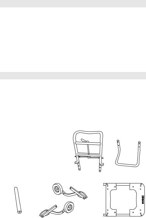
TS2000 TABLE SAW STAND
PACKAGE CONTENTS:
Item Qty. Part Description
A(1) Upper Cross Bar
B(1) Lower Cross Bar
C(1) Kickback Bar
D(1) Right Leg/Wheel Assembly
E(1) Left Leg/Wheel Assembly
F(1) Table Top
E
C
D
TOOLS REQUIRED:
Phillips screwdriver, 10 MM open end wrench, 16 MM open end wrench, or adjustable wrench.
BEFORE YOU ASSEMBLE THIS
TABLE SAW STAND:
Sort out and account for all parts to make sure that you have all necessary materials to assemble your stand. Do not discard packing material until all parts are accounted for.
A
B
F
-2-
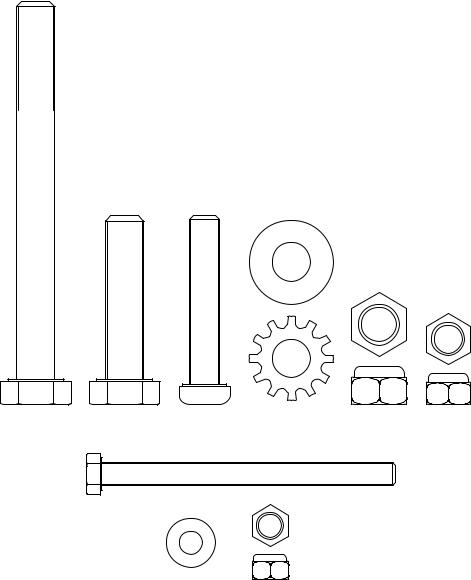
STAND ASSEMBLY HARDWARE (packaged in one bag)
Item |
Qty. |
Part Description |
G |
6 |
10mm x 100mm Hex Head Bolts |
H |
2 |
10mm x 50 mm Hex Head Bolts |
I |
6 |
8mm x 50 mm Phillips Head Screws* |
J |
18 |
10mm Flat Washers |
K2 10mm Star Washers
L6 10mm Lock Nuts
M6 8mm Lock Nuts*
N4 6mm x 75mm Hex Head Bolt
O8 6mm Flat Washer
P |
4 6mm Lock Nuts |
|
|
|
J |
G |
H |
I |
L |
|
M
K
N
O P
*Note: There are two (2) 8mm x 50mm Phillips head screws and two (2) 8mm lock nuts to be used only when attaching other branded table saws to the Bosch TS2000 stand. See page 6 for instructions.
-3-

Assembly
Step 1
Attach Upper and Lower Cross Bars
1.Position lower cross bar on a flat surface as shown in figure A.
2.Insert ends of upper cross bar into the lower cross bar and push downward as far as it will go.
3.Insert four (4) 8 mm x 50 mm Phillips Head Screws through the holes of the upper and lower cross bars, and securely tighten with four (4) 8 mm lock nuts as shown.
Step 2
Attach Leg/Wheel Assemblies
1.Locate the right leg/wheel assembly and position on right side of upper/lower cross bar assembly as shown in figure B.
2.Place one (1) flat washer onto one (1) 10
mmx 100 mm bolt and insert through right leg/wheel assembly.
3.Place another (1) 10 mm flat washer on bolt between leg/wheel assembly and upper/lower cross bar assembly.
4.Insert bolt through upper/lower cross bar assembly, place one (1) 10 mm flat washer, and loosely tighten with one (1) 10
mmlock nut.
Note: Do not over-tighten lock nut - these parts need to freely rotate for stand to operate properly.
Repeat procedure on left side.
FIG. A
FIG. B
Lock Nut |
Upper |
Leg/Wheel |
Bolt |
|
Cross Bar |
Assembly |
|||
|
|
Washer |
Washer |
Washer |
-4-

Step 3 |
FIG. C |
Attach Kick Bar
1. Locate the kick bar and position it between the left and right wheel assemblies as shown in figure C.
2. Place one (1) 10 mm star washer onto one
(1) 10 mm x 50 mm hex head bolt. Insert bolt through the leg/wheel assembly and thread it into the the kick bar and securely tighten.
Repeat this procedure on other side.
Step 4
Attach Table Top
1.Locate the table top and position holes in end of table top with holes in upper cross bar as shown in figure D.
2.Place one (1) flat washer onto one (1) 10 mm x 100 mm bolt.
3.Insert bolt through table top and place another (1) flat washer on bolt between table top and upper cross bar.
4.Insert bolt through upper cross bar, place one (1) flat washer, and loosely tighten with one (1) 10 mm lock nut.
Note: Do not over-tighten lock nut - these parts need to freely rotate for stand to operate properly.
Repeat this procedure on opposite side.
FIG. D
Lock Nut |
Upper |
Table Top |
Bolt |
|
Cross Bar |
|
|
Washer |
|
Washer |
Washer |
Step 5
Attach Linkage Bars
1.Align hole in upper linkage bar with hole in table top as shown in figure E.
2.Place one (1) flat washer onto one (1) 10 mm x 100 mm bolt.
3.Insert bolt through linkage bar and place another (1) flat washer on bolt between table top and upper cross bar.
4.Insert bolt through table top, place one (1) flat washer, and loosely tighten with one
(1) 10 mm lock nut.
Note: Do not over-tighten lock nut - these parts need to freely rotate for stand to operate properly.
Repeat this procedure on opposite side.
FIG. E
Lock Nut |
Table Top |
Linkage |
Bolt |
|
|
Bar |
|
Washer |
|
Washer |
Washer |
-5-

Assembly
For Mounting Bosch 4000
Table Saw to Stand
1.Using the diagram below, locate the Bosch 4000 mounting holes and position saw on stand as shown in figure F.
2.Place one (1) 6 mm flat washer onto one
(1) 6 mm x 75 mm hex head bolt and insert bolt through mounting hole in table saw and through stand table top.
3.Place one (1) 6 mm flat washer and securely tighten with one (1) 6 mm lock nut.
Repeat this procedure on the three remaining mounting holes.
For Mounting Other Table Saws
Important: Before mounting a DeWalt, Craftsman, Makita, Hitachi, or Ridgid table saw, insert two (2) 8mm x 50mm Phillips head screws through “B*” hole locations and tighten using 8mm lock nuts.
1.Using the diagram below, locate the correct mounting holes for the table saw being used and position saw on stand accordingly.
For use with Hitachi Table Saw:
If your TS2000 stand does not have "H" holes, you will need to drill holes. Place the saw over the center of the opening and make pencil marks (through the L-shaped bracket holes) on the table top mounting plates. Remove saw and drill four (4) 5/16" diameter holes through the mounting plates.
For use with Ridgid Table Saw:
Locate the four “R” holes in the two mounting plates and drill four (4) 3/8” diameter holes completely through the stand’s frame.
2.Mount the table saw using the appropriate mounting hardware for your table saw model.
FIG. F
|
Mounting |
Table Saw Models |
Holes |
Bosch 4000 |
B |
Dewalt DW744 |
D |
Craftsman 21830 |
C |
Makita 2703 |
M |
Hitachi C10RA2** |
H |
Ridgid TS2400LS** |
R |
**See instructions. |
|
-6-

Operating Instructions
|
Fold Stand Upright |
||
|
|
Keep fingers clear of |
|
! |
WARNING |
||
hinge points when folding |
|||
|
|
||
or unfolding the stand.
1.Slightly lift stand by the black handle.
2.Rotate release lever down to clear locking pins.
3.With both hands on the handle, pull up and push forward on the stand, figure B, until it locks in the upright position, figure C.
Lower Stand
1.Rotate the release lever, then pull back on the stand slightly to disengage.
2.With both hands on the handle, pull back and lower the stand until it locks in position.
FIG. A
FIG. C
FIG. B
Kickbar
Lowering Stand to its Lowest Position
Begin with the stand in the locked upright position, as shown above in figure C.
Firmly grip the handle with both hands and place one foot against the kick bar. Pull back on the handle and lower the stand to the ground, as shown.
-7-
Operating Instructions
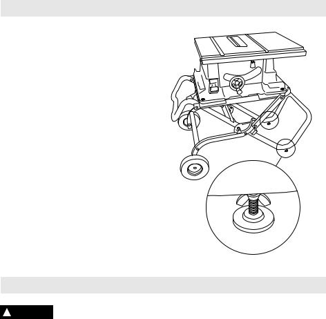
To level stand
The stand is equipped with two adjustable feet for leveling the stand.
To adjust: loosen wing nut and adjust the height of the foot by screwing the threaded shaft clockwise to raise foot or counterclockwise to lower foot. Retighten wing nut securely.
Maintenance
To reduce the risk of injury, ! WARNING periodically check that all
fasteners are attached and adjusted according to the assembly instructions included in this manual.
Tire Pressure
The TS2000 tires are shipped with an air pressure of 25 to 30 P.S.I. — an adequate pressure for most working conditions. If you wish to increase the tire pressure for a slightly firmer support, you may inflate the tires to a maximum of 50 P.S.I. It is recommended that a hand pump is used.
-8-
 Loading...