


Bosch T5600S 15 D 31, T5600S 15 D 23, T5600S 17 D 31, T5700S 12 D 23, T5700S 15 D 23 Training And Service Information
...
Page 1 from 43 6 720 887 547 “SM FP_ErP MPP Europe 2018/08 en”
LOW NOX INSTANTANEOUS
GAS WATER HEATER
ROOM SEALED PRESSURIZED
GAS WATER HEATER
FOR INDOOR INSTALLATION
TRAINING AND SERVICE INFORMATION FOR AFTER SALES
This document is restricted to exclusive use by the official service partners. Each
country should adapt the manual and its contents to the available range.

Page 2 from 43 6 720 887 547 “SM FP_ErP MPP Europe 2018/08 en”
Contents
1. INTRODUCTION ..............................................................................................3
2. APPLIANCE DESCRIPTION ............................................................................3
2.1 APPLIANCE DESIGNATION ...................................................................................................... 3
2.2 AVAILABLE ACCESSORIES ..................................................................................................... 3
3. INSTALLATION ................................................................................................5
3.1 APPLIANCE FIXATION ON THE WALL ........................................................................................ 5
3.2 WATER CONNECTIONS ........................................................................................................... 6
3.3 GAS CONNECTION ................................................................................................................. 6
3.4 APPLIANCE PERFORMANCE .................................................................................................... 7
4. COMPONENTS OVERVIEW ............................................................................8
4.1 CONTROL PANEL................................................................................................................... 9
4.2 HEAT CELL WITH BURNER PIPES ........................................................................................... 12
4.3 GAS MANIFOLD ................................................................................................................... 13
4.4 FAN ................................................................................................................................... 14
4.5 GAS VALVE ........................................................................................................................ 14
4.6 HEAT EXCHANGER .............................................................................................................. 15
4.7 WATER INLET ASSY ............................................................................................................ 17
4.8 WATER TEMPERATURE SENSORS ......................................................................................... 17
4.9 BOX TEMPERATURE SENSOR ............................................................................................... 18
4.10 WATER FLOW SENSOR ..................................................................................................... 18
4.11 IGNITION ELECTRODE ....................................................................................................... 19
4.12 IONIZATION ELECTRODE .................................................................................................... 20
5. WORKING PRINCIPLE / ELECTRIC MEASUREMENTS ............................ 21
6. SERVICE ....................................................................................................... 29
7. MAINTENANCE ............................................................................................. 38
8. TROUBLE SHOOTING .................................................................................. 41

Page 3 from 43 6 720 887 547 “SM FP_ErP MPP Europe 2018/08 en”
1. Introduction
This manual is a complement to the instruction/operation manual delivered with the
appliance, with the main important technical details that are relevant for the official service
partners and trainers in the country. In any case one of the documents replaces the use of
the other, so always ensure after sales service have updated manuals supplied with the
product, spare part list to be used as complement of this specific service manual.
2. Appliance description
This appliance is a LOW NOx gas water heater (ErP directive demands < 56 mg/kWh),
which will replace the actual room sealed forced exhaust range of appliances offering a
wider range of modulation and installation advantages.
2.1 Appliance Designation
The designation allows the identification of the main characteristics of the units, especially when
report is needed through call centre or after sales technicians.
Example of variants:
T5600S 12/15/17 D 23/31
T5700S 12/15/17 D 23/31
WTD 12/15/17-3 AME 23/31
WTD 12/15/17-4 AME 23/31
Bosch:
T – Instantaneous gas water heater
T 5600 – Thermostatic control (variable power through electronic control)
T 5700 – Thermostatic control (variable power through electronic control with water valve)
T … S – Room sealed operation (indoor unit)
T … S 12 / 15 / 17 – Output (flow rate at 25ºC rise)
T … S XX D – Display
T …S XX D 23/31 – Gas type (23 = natural gas / 31 = liquefied petroleum gas)
Junkers / Vulcano:
WT -3 – GWI Thermostatic control (variable power through electronic control)
WT -4 – GWI Thermostatic control (variable power through electronic control with water valve)
WT D – Display
WT D 12 / 15 / 17 – Output (flow rate at 25ºC rise)
WT D… AM – Room sealed operation (indoor unit)
WT D… AM E – Electric connection
WT D… AM E 23/31 – Gas type (23 = natural gas / 31 = liquefied petroleum gas)
2.2 Available accessories
Hydraulic & Gas Connections (supplied together with set of documents) with installation manual
for each destination market are the original accessories and must be used by installer (see
manual to check scope of delivery.
Page 4 from 43 6 720 887 547 “SM FP_ErP MPP Europe 2018/08 en”
Remote control
Possible wired connection to both indoor (optional accessory) and outdoor versions
(included in packaging). This is done with a direct connection to the appliance with no
need to configure in the unit the existence of the wired remote control.
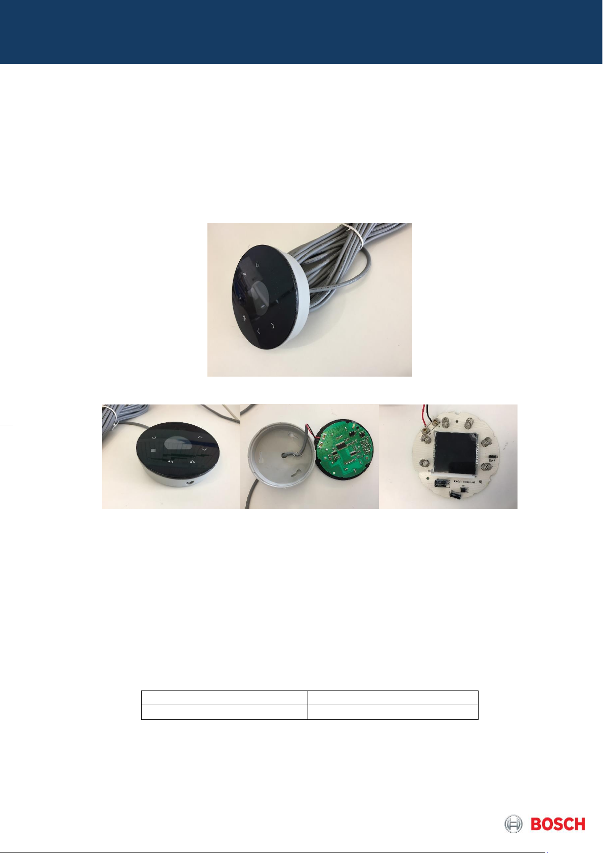
The kit includes 10 m of cable which needs to be connected to the remote by opening the
back cover (rotation) and then removing 3 screws to release the circuit board and make
the connection in the available connection.
Pict. 1 – Wired remote scope of delivery
Pict. 2 – Remote Control View and connection
Anti-Freeze
Allows the protection of the appliance against water freezing inside of its pipes until -20ºC
and to be used in cases where ambient temperature can be lower than 5ºC. It is optional
for indoor models but included from factory in outdoor models.
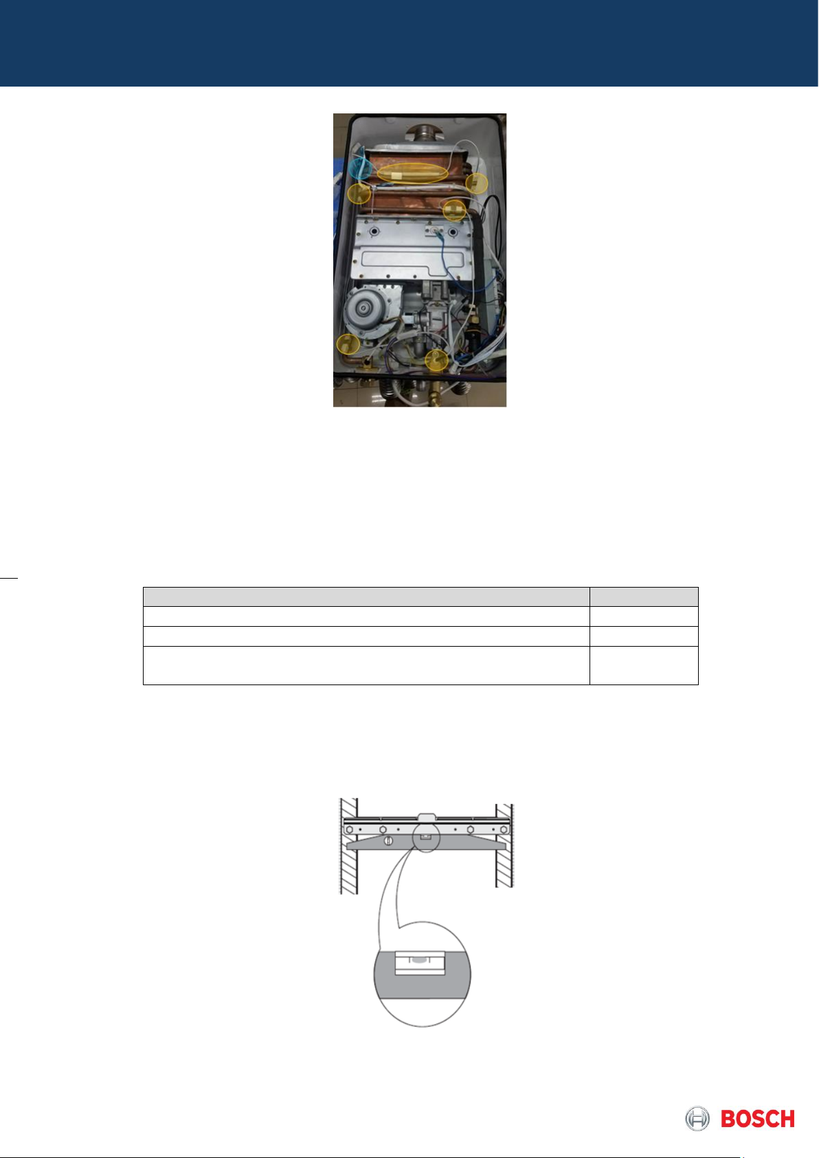
This kit includes 6 heating elements and 1 sensor (in blue at picture) to install in the heat
exchanger and the activation is according conditions in table 1.
Activation
Deactivation
T
sensor
≤ 4ºC
T
sensor
≥ 15ºC
Table 1 – Anti-freeze activation conditions
Page 5 from 43 6 720 887 547 “SM FP_ErP MPP Europe 2018/08 en”
Pict. 3 – Anti-Freeze Kit in appliance
3. Installation
The installation manual of each product must be checked and used by the installer in order
to optimize and leave the appliance in correct operation conditions.
3.1 Appliance fixation on the wall
Requisite
Confirmation
Appliance is levelled and in the vertical position?
Delivered accessories are used accordingly?
Appliance is supported exclusively by the wall fixation and
not by hydraulic and/or gas connections?
Table 2 – Check List for Fixation
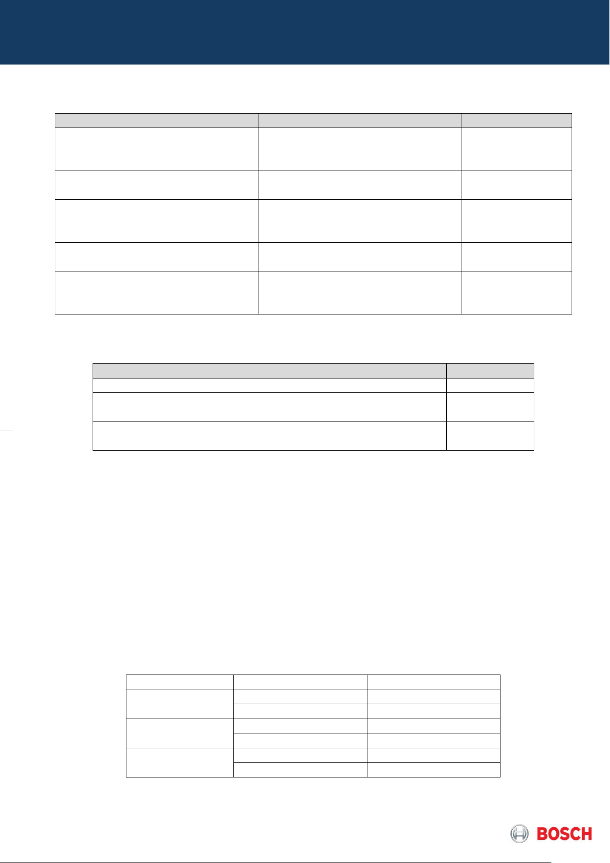
Installer must ensure correct wall fixation and water / gas pipe positions using supplied
accessories as the wall hung bracket.
Pict. 4 – Wall Fixation Preparation
Page 6 from 43 6 720 887 547 “SM FP_ErP MPP Europe 2018/08 en”
3.2 Water connections
Requisite
Observations
Confirmation
Water pipes were cleaned
before connected to the
appliance?
Leakage test was done
successfully?
Inlet water filter was checked
and is cleaned, ensuring the
necessary water flow?
Accessories for water
connections are adequate?
Water pressure and flow are
according to the appliance
specifications?
- Nominal pressure: 1- 4 bar
- Minimum pressure: 0,15 bar
- Maximum pressure: 12 bar
Table 3 – Check list hydraulic connections
3.3 Gas connection
Requisite
Confirmation
The appliance is suitable for the available gas type?
Pressure reducer and gas pipe are adequate for the required
pressure and gas flow?
Accessories for gas connection are adequate and according to
the country specification/standards?
Table 4 – Check list for gas connections
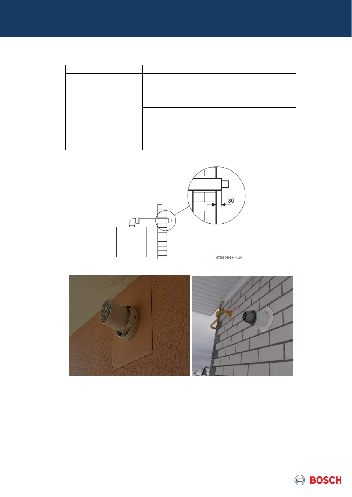
3.4 Flue Exhaustion
The correspondent appliance manual have indicated the maximum flue length according model
and flue type orientation so will be required to have configured in HMI.
Flue Exhaustion
▶ Access menu AA.
▶ Scroll until find F9.
▶ Press ok
▶ Scroll and select the flue length
▶ Press ok
Length selected
Model
Flue Length
Parameter
12
0 – 4 m
00
= 4
01
15
0 – 2 m
00
2 – 4 m
01
17
0 – 2 m
00
2 – 4 m
01
Table 5 – Flue Configurations for MPP1 (5600)
Page 7 from 43 6 720 887 547 “SM FP_ErP MPP Europe 2018/08 en”
Model
Flue Length
Parameter
12
0 – 4 m
00
4 – 8 m
01
8 – 12 m
02
15
0 – 2 m
00
2 – 4 m
01
4 – 8 m
02
17
0 – 2 m
00
2 – 4 m
01
4 – 8 m
02
Table 6 – Flue Configurations for MPP2 (5700)
Pict. 5 – Wall distance in mm required in horizontal termination
Pict. 6 – Example of wall terminations in 80/110 and 60/100 type
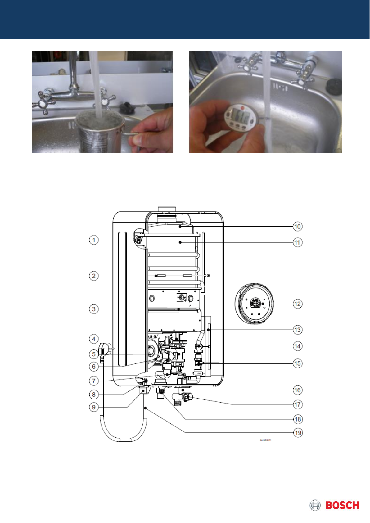
3.5 Appliance performance
Measure water flow and temperature increase to check temperature and instantaneous
water flow, assuring correct operation of the appliance.
Page 8 from 43 6 720 887 547 “SM FP_ErP MPP Europe 2018/08 en”
Pict. 7 – Use of water flow meter and thermometer
4. Components Overview
[1] Temperature limiter
[2] Thermo-fuse
[3] Burner
[4] Gas manifold
[5] Gas valve
[6] Fan
[7] Gas pipe
[8] Outlet Temperature sensor
[9] Hot water
[10] Flue collector
[11] Heat Exchanger
[12] HMI
Page 9 from 43 6 720 887 547 “SM FP_ErP MPP Europe 2018/08 en”
[13] Control Unit
[14] Inlet Temperature sensor
[15] Flow sensor
[16] Cold water
[17] Flow rate control
[18] Gas inlet
[19] Electrical supply cable
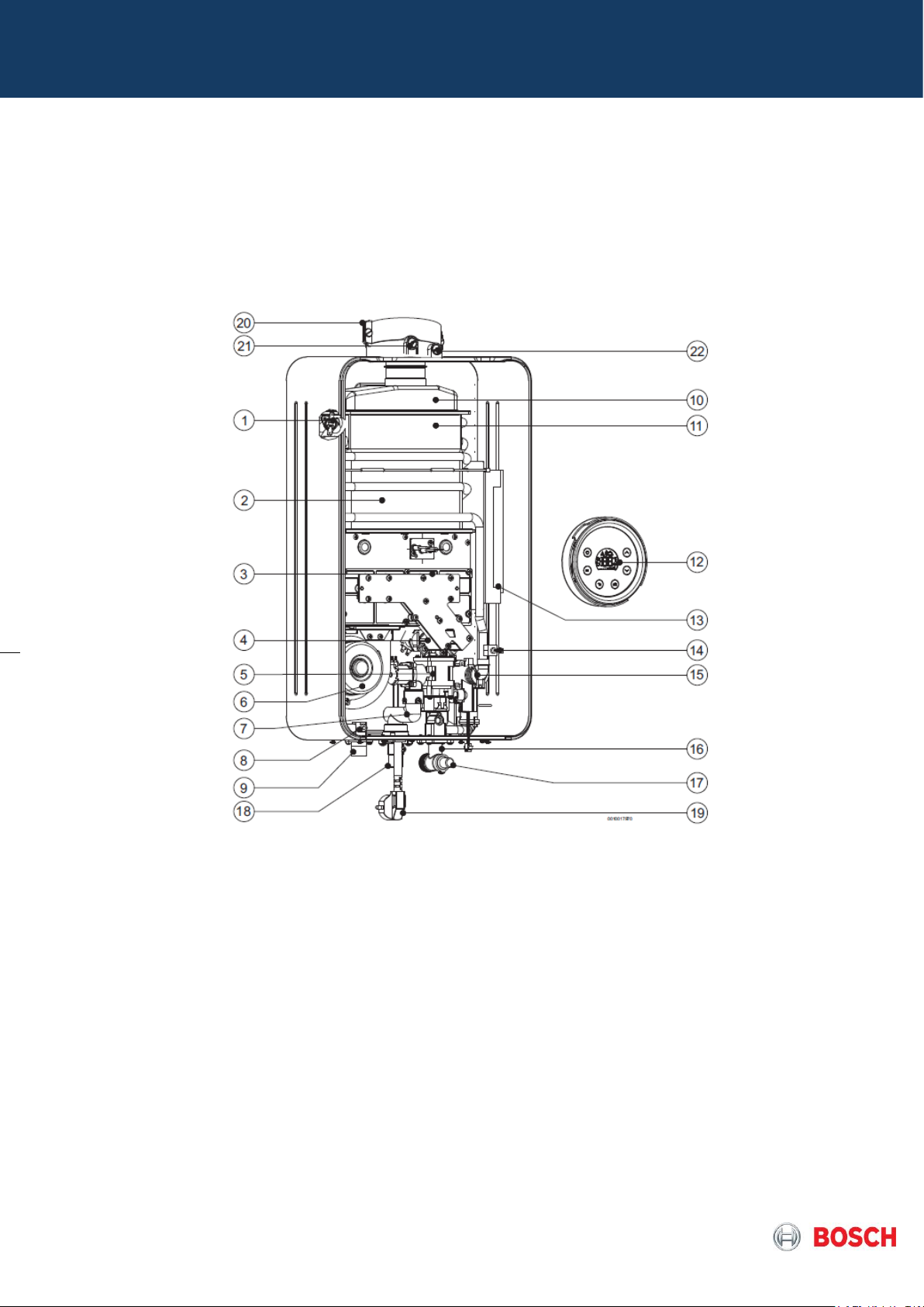
Pict.8 – Internal layout (example of MPP1)
[1] Limiteur de température
[2] Fusible
[3] Brûleur
[4] Collecteur de gaz
[5] Bloc gaz
[6] Ventilateur
[7] Tuyau de gaz
[8] Sonde de température de soufflage
[9] Eau chaude
[10] Collecteur des fumées
[11] Échangeur thermique
[12] IHM
[13] Tableau de régulation
[14] Sonde de température d'entrée
[15] Vanne d’eau avec detecteur de débit
[16] Eau froide
[17] Commande du débit
[18] Entrée de gaz
[19] Câble d'alimentation électrique
Pict.9 – Internal layout (example de MPP2 / T5700)
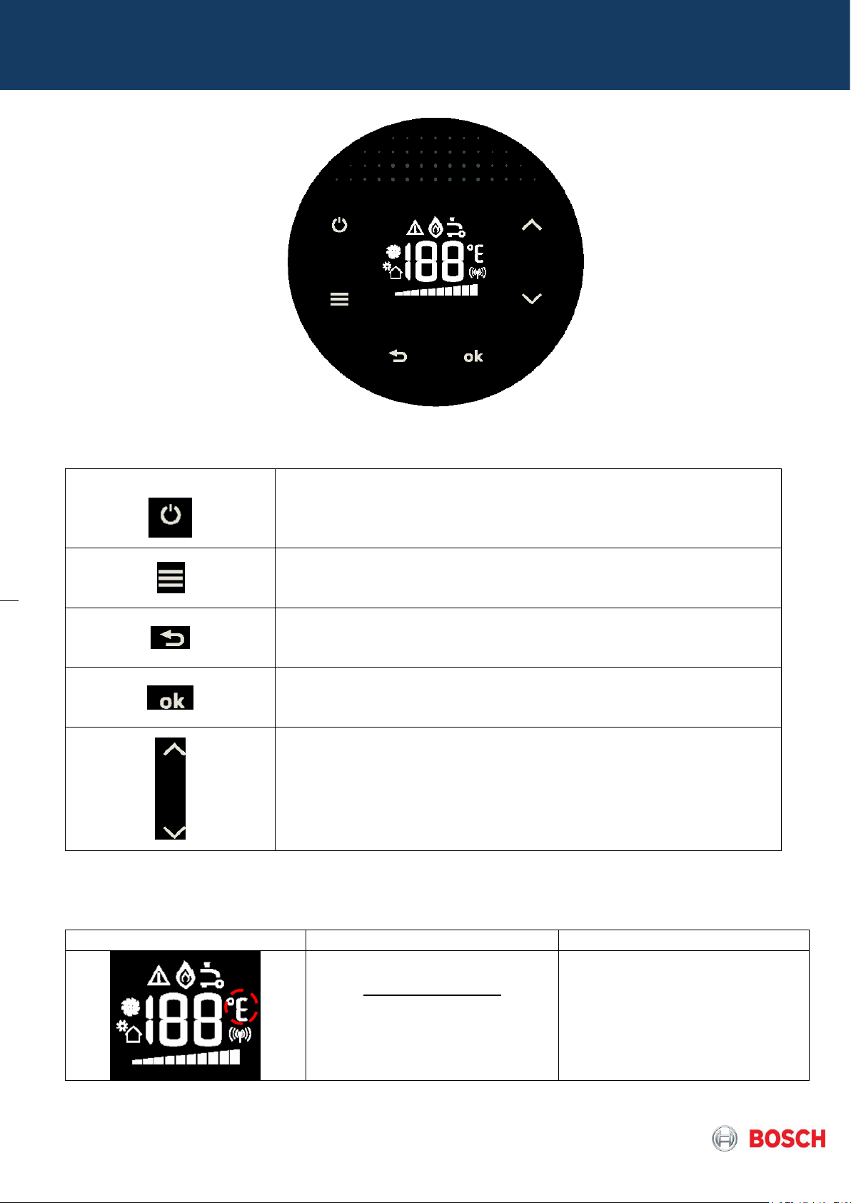
4.1 Control panel
The control panel allows the user, installer or technician, to perform all different operations
needed. User manual explain how to access and use the HMI (human machine interface).
Page 10 from 43 6 720 887 547 “SM FP_ErP MPP Europe 2018/08 en”
Pict.10 – Control Panel HMI Overview T5600-T5700
On / Off button
The main switch is assembled on the PCB and disconnects the
unit so no voltage at components is present although anti-freeze
kit keeps active due to temperatures checks even in Off mode.
Menu Button
- Used to Enter in service mode to access service parameters
which can be used by the user, installer, technician
Program Button
- Used to Scroll back in the service mode menu when navigating
menus
OK Button
- Save value or adjust set values
- Save a temperature setting (user)
Selection button
Used to scroll inside menu ensuring navigation on parameters
inside the diagnostic mode
Table 6 – Control Panel Buttons
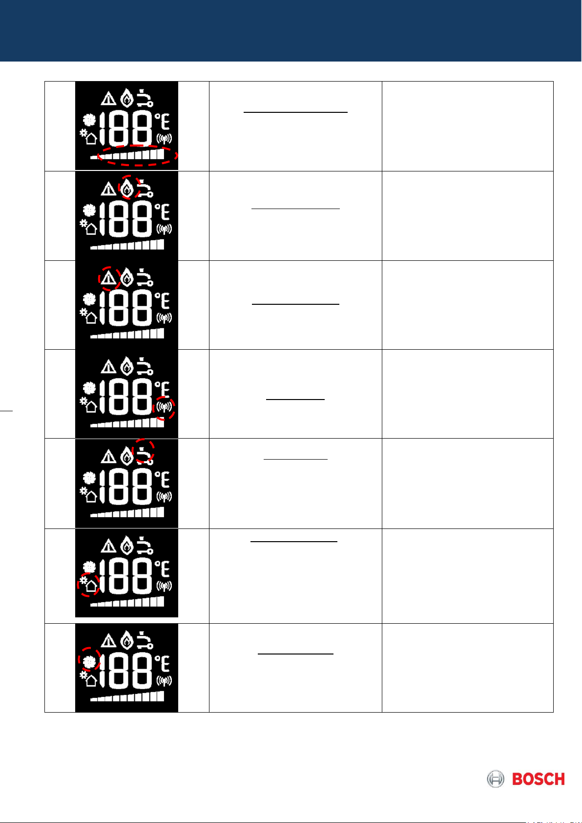
Symbol
Description
Observation
Temperature Unit:
ºC – default value
ºF – alternative value
Selection can be done by
changing default value on
service mode (P6) inside SA
(settings) parameter
Page 11 from 43 6 720 887 547 “SM FP_ErP MPP Europe 2018/08 en”
Power bar indicator:
Indication of the current
operation power
Indicative Value (in %)
Note: each segment of the bar
represents 10% of power from 0
to maximum power in kW
Flame indication:
Indication of flame in the
burner
Symbol displayed when
ionization is detected - flame
presence
Warning symbol:
Error / warning symbol is turned
ON every time there is an error or
a warning
Connectivity
Connectivity symbol is ON when
a mobile device is connected to
the water heater wifi module
Tap symbol:
Indication of not enough power
to reach set point.
Note: In case symbol is displayed,
decrease (-) or increase (+) flow
accordingly
Excessive water flow symbol is ON
when the setpoint ±3ºC cannot be
reached at maximum
power because there is too much
water going through the water
heater, or at minimum power
because there is not enough water
going through the water heater
Solar application:
Indication that the automatic
solar function is activated,
meaning that the appliance is
receiving pre-heated inlet
water, with no need for burner
to start
The symbol is displayed and
burner is shutdown when T in
is under following conditions:
T in ≥ T
set
– 1K
The symbol is deactivated and
burner restarted when:
T
out
< 60ºC
Fan operation:
Indication that the fan is in
operation
Fan rotation detection symbol is
ON when rotation of the fan
speed is detected
Table 7 – Display Symbols
Page 12 from 43 6 720 887 547 “SM FP_ErP MPP Europe 2018/08 en”
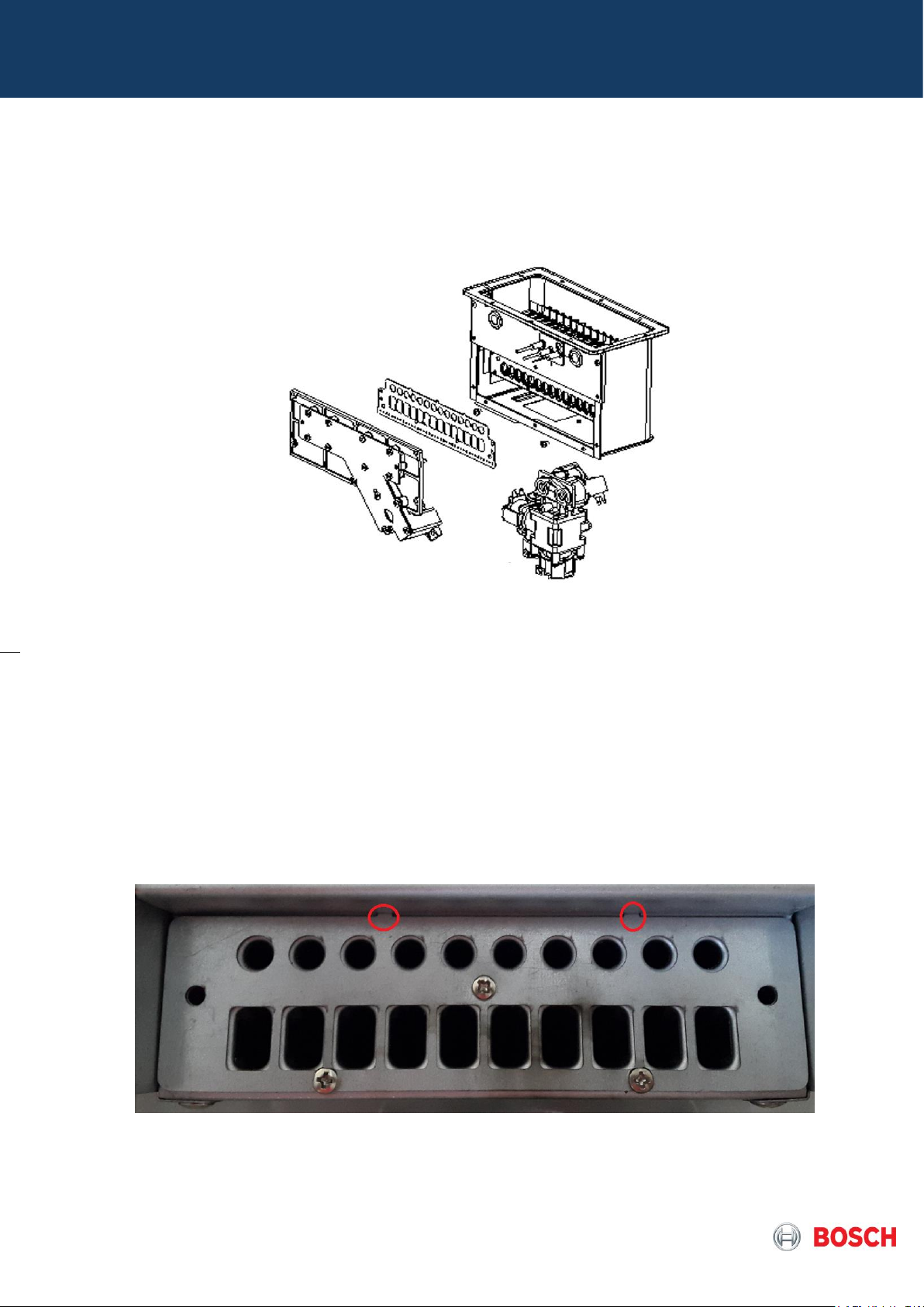
4.2 Heat cell with burner pipes
The heat cell includes the copper heat exchanger and the burner with flame visualization
window, ignition electrode and ionization electrode and the gas manifold for the burner.
Pict.11 – Burner and gas valve view
Primary air plate
In the burner there is a primary air plate assembled between the gas manifold with
injectors and the burner itself in order to ensure the correct mixture of air and gas
according to the specific appliance model.
The plate has indexation pins that ensure the correct assembly on the heat cell and must
be always replaced together with the injectors in gas conversion.
Pict. 12 – Primary air plate
Page 13 from 43 6 720 887 547 “SM FP_ErP MPP Europe 2018/08 en”
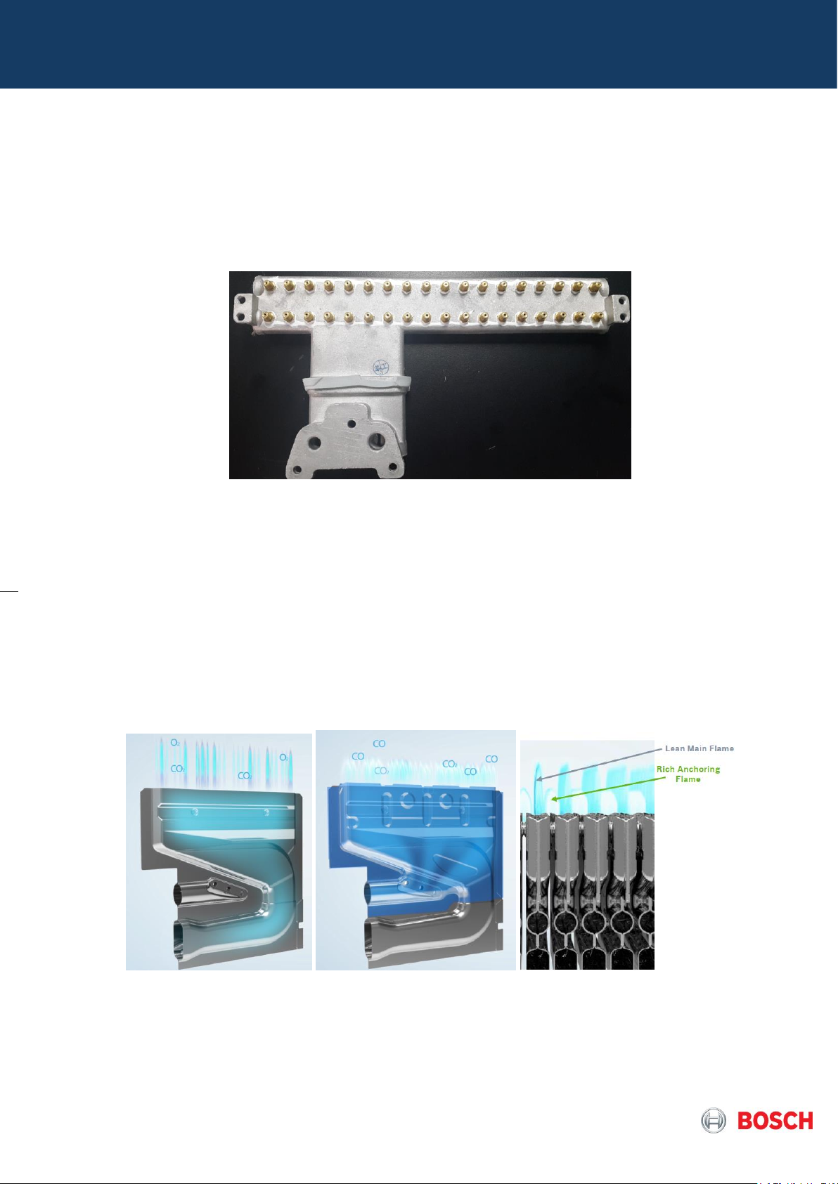
4.3 Gas manifold
The gas manifold is a gas distribution pipe with 2 types of injectors as in this burner there
are two distinct primary flames with different air/fuel ratios and during whole burning
process flue temperature is kept low reducing the emission of NOX assured by lean
combustion and the mandatory flame stability ensured by rich flame
Pict. 13 – Gas manifold injectors
This manifold is part of the gas conversion kit and injectors are not to be replaced individually,
so the kit will always supply the complete manifold. The stamp indicates the size of injectors
used for reference.
The Burner design allows to have on the same burner surface:
- One primary rich flame (oxygen enriched combustion for stabilization) which
corresponds to the injectors with smaller diameter in top of manifold
- One primary lean flame (lack of oxygen for low NOx emissions) which corresponds to
the injectors with bigger diameter in the bottom of manifold.
Pict.14 – Burner design and working principle
The manifold cover allows the gas supply to the burner over 2 different segments, in order
to assure a wide modulation, range according to the capacity of the appliance,
nevertheless in the MPP models, the segmentation is automatically selected according
power demand.
 Loading...