

Bosch Rotocut Operating Instructions Manual
Euro • Printed in USA • BA 2 610 998 773 • Rotocut • Titel (Vorderseite) • OSW 08/00
Rotocut - Buch Seite 1 Dienstag, 15. August 2000 10:23 10
Bedienungsanleitung
Operating Instructions
Instructions d’emploi
Instrucciones de servicio
Manual de instruções
Istruzioni d’uso
Gebruiksaanwijzing
Betjeningsvejledning
Bruksanvisning
Brukerveiledningen
Käyttöohje
O‰ЛБ›· ¯ВИЪИЫМФ‡
Kullanım kılavuzu
Rotocut
Deutsch
English
Français
Español
Português
Italiano
Nederlands
Dansk
Svenska
Norsk
Suomi
EППЛУИО¿
Türkçe
Euro • Printed in USA • BA 2 610 998 773 • Rotocut • Titel Umschlagseite 2 • OSW 08/00
Rotocut - Buch Seite 2 Dienstag, 15. August 2000 10:23 10
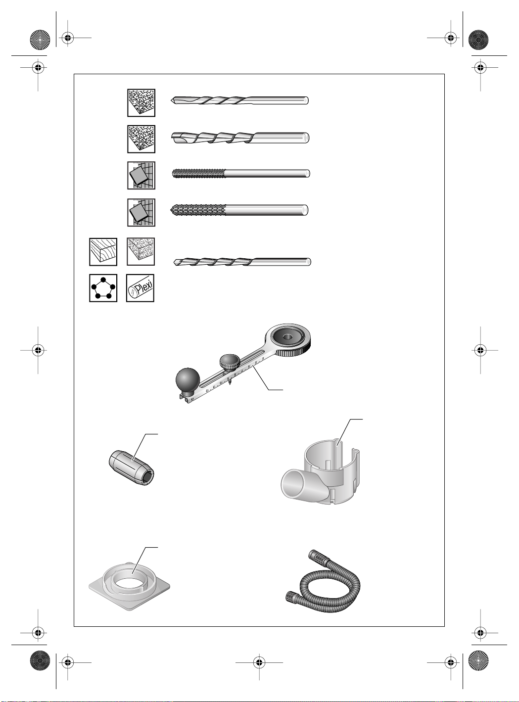
B 32 C
3,2 mm (1/8")
2 608 620 201 (10x)
B 64 C
6,4 mm (1/4")
2 608 620 200 (1x)
PVC
soft
soft
B 32 G
3,2 mm (1/8")
2 608 620 202 (1x)
B 64 G
6,4 mm (1/4")
2 608 620 204 (1x)
B 32 CU
3,2 mm (1/8")
2 608 620 203 (5x)
2 608 620 207
2 610 998 773 • 08.00
11
8
5
10
3,2 mm (1/8")
2 608 620 205
6,4 mm (1/4")
2 608 620 206
2 608 000 280
ø 19 mm
2 608 601 155
1 610 793 002
5 m
2 600 793 009
3 m
Euro • Printed in USA • BA 2 610 998 773 • Rotocut • Titel Umschlagseite 3 • OSW 08/00
Rotocut - Buch Seite 3 Dienstag, 15. August 2000 10:23 10
2 610 998 773 • 08.00
Euro • Printed in USA • BA 2 610 998 773 • Rotocut • Titel Umschlagseite 4 • OSW 08/00
Rotocut - Buch Seite 4 Dienstag, 15. August 2000 10:23 10
9
ON
OFF
1
2
3
4
5
6
7
8
2 610 998 773 • 08.00
Euro • Printed in USA • BA 2 610 998 773 • Rotocut • Titel Umschlagseite 5 • OSW 08/00
Rotocut - Buch Seite 5 Dienstag, 15. August 2000 10:23 10
A
C
2 610 998 773 • 08.00
2 4
I
B
3
2
3
4
3 mm
D
7 6
II
13 12 7
E F
6 mm
. 1
2
3
5
6
7
8
9
Euro • Printed in USA • BA 2 610 998 773 • Rotocut • D • OSW 08/00
Rotocut - Buch Seite 1 Dienstag, 15. August 2000 10:23 10
■
■
■
■
■
Gerätekennwerte
Rotocut
Bestellnummer 0 601 638 1..
Nennaufnahme* 450 W
Leerlaufdrehzahl 30 000 min
-1
Spannzangen-Ø 3,2 mm (1/8")
Spannzangen-Ø 6,4 mm (1/4")
Gewicht (ohne Zubehör) ca. 1,2 kg
Schutzklasse
* Angaben gelten für Nennspannungen [U] 230/240 V. Bei
niedrigeren Spannungen und in länderspezifischen Ausführungen können diese Angaben variieren.
/ II
Geräusch-/Vibrationsinformation
Messwerte ermittelt entsprechend EN 50 144.
Der A-bewertete Geräuschpegel des Gerätes be-
trägt typischerweise: Schalldruckpegel 79 dB (A);
Schallleistungspegel 92 dB (A).
Gehörschutz tragen!
Die Hand-Arm-Vibration ist typischerweise niedriger als 2,5 m/s
2
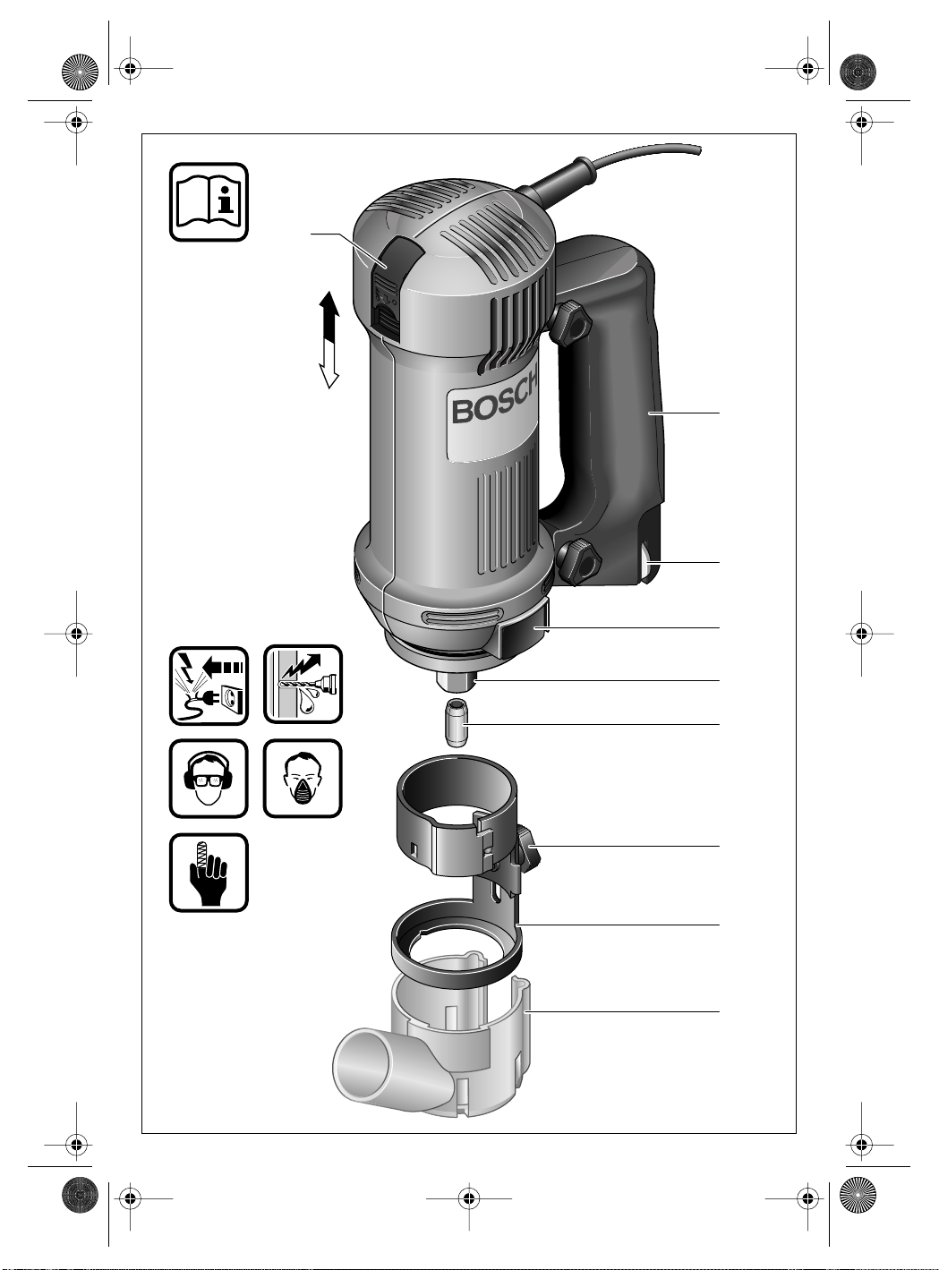
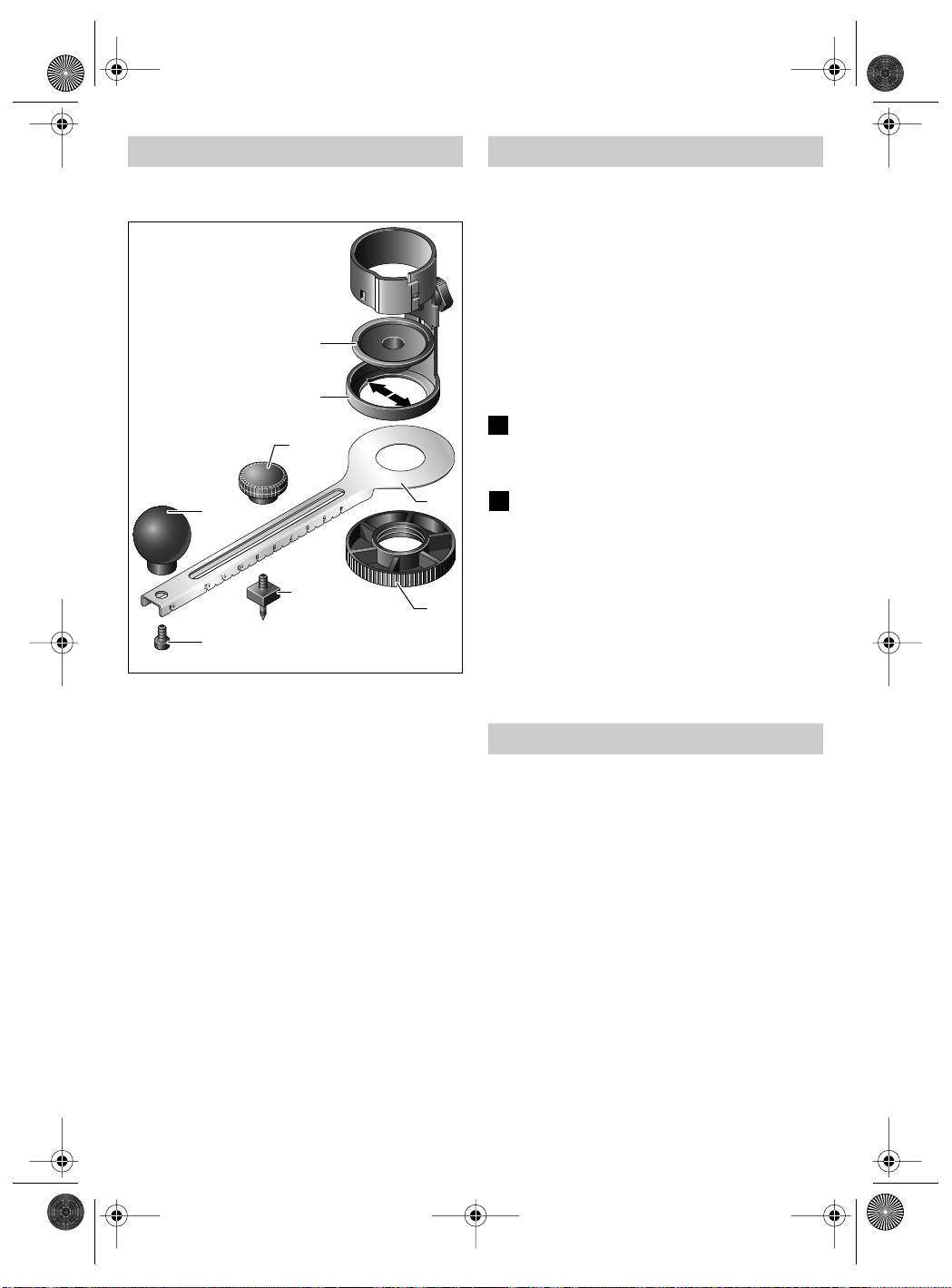
Geräteelemente
Zusatzgriff
Gabelschlüssel (SW 16)
Spindellock-Taste
4 Überwurfmutter
Spannzange 3,2 mm (1/8")
Spannzange 6,4 mm (1/4")
Rändelschraube
Verstellbare Fußplatte
Absaugstutzen (für Schlauch Ø 19 mm)
Ein-/Ausschalter
10 Gleitschuh
11 Kreisschneider
12 Ausbuchtung
13 Blechnase
Abgebildetes oder beschriebenes Zubehör gehört
teilweise nicht zum Lieferumfang.
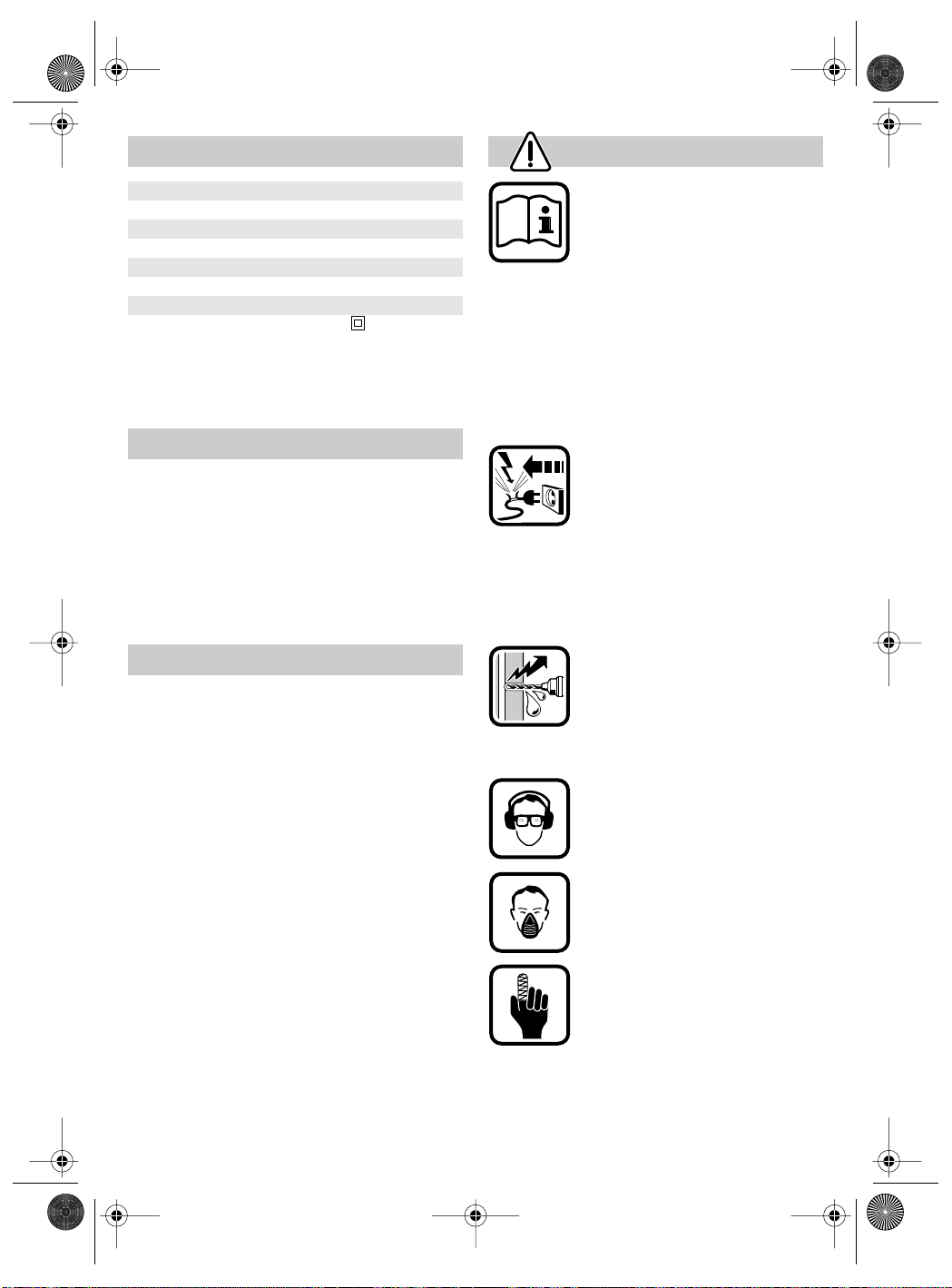
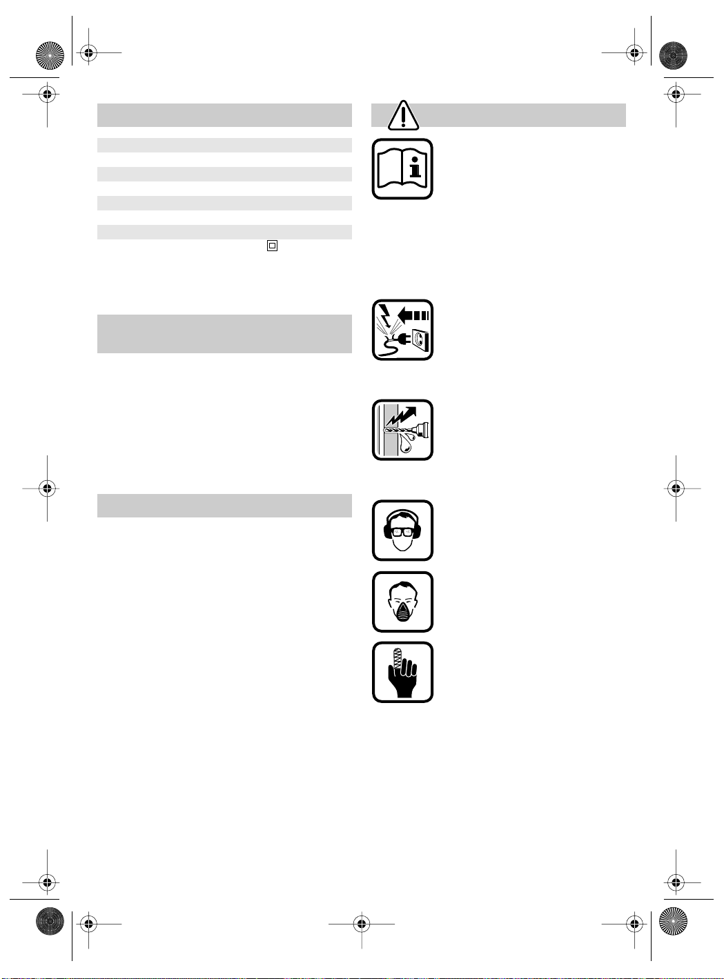
Zu Ihrer Sicherheit
Gefahrloses Arbeiten mit dem
Gerät ist nur möglich, wenn Sie
die Bedienungsanleitung und die
Sicherheitshinweise vollständig
lesen und die darin enthaltenen
Anweisungen strikt befolgen. Zusätzlich müssen die allgemeinen
Sicherheitshinweise im beigelegten Heft befolgt werden. Lassen
Sie sich vor dem ersten Gebrauch praktisch einweisen.
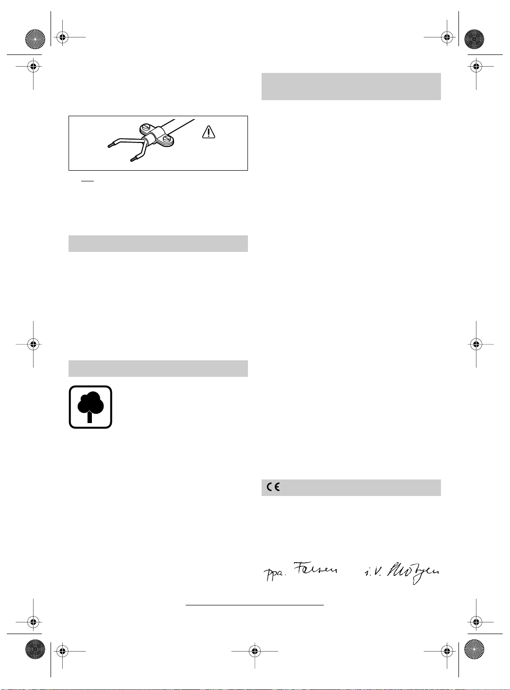
Netzstecker ziehen.
Wird bei der Arbeit das Netzkabel
beschädigt oder durchtrennt, Kabel
nicht berühren, sondern sofort den
Netzstecker ziehen. Gerät niemals
mit beschädigtem Kabel benutzen.
Beschädigung.
Beim Schneiden in Ecken und Wänden die Bearbeitungsstelle vorher
auf unsichtbar verlegte Strom-,
Gas- und Wasserleitungen untersuchen, z. B. mit einem Metallortungsgerät.
Schutzbrille und Gehörschutz
tragen.
2 610 998 773 • TMS • 10.08.00
Staubschutzmaske tragen.
Verletzungsgefahr
Scharfes Einsatzwerkzeug.
Beim Arbeiten das Gerät immer fest mit beiden
Händen halten und für einen sicheren Stand
sorgen.
Stecker nur bei ausgeschaltetem Gerät in die
Steckdose einstecken.
Kabel immer nach hinten vom Gerät wegführen.
Asbesthaltiges Material darf nicht bearbeitet
werden.
Hände weg von rotierendem Schneidewerkzeug.
Deutsch - 1
Euro • Printed in USA • BA 2 610 998 773 • Rotocut • D • OSW 08/00
Rotocut - Buch Seite 2 Dienstag, 15. August 2000 10:23 10
■
■
■
■
4
4
2
5
4
3
4
■
■
I
6
Das Gerät nur eingeschaltet gegen das Werkstück führen.
Gerät vor dem Ablegen immer ausschalten
und auslaufen lassen.
Bosch kann nur dann eine einwandfreie Funktion des Gerätes zusichern, wenn für dieses
Gerät vorgesehenes Original-Zubehör verwendet wird.
Bestimmungsgemäßer Gebrauch
Das Gerät ist bestimmt zum Schneiden von Gips,
Holz, Plexiglas, Kunststoff und
fliesen.
weichen Wand-
Werkzeugwechsel
Vor allen Arbeiten am Gerät Netzstecker
ziehen.
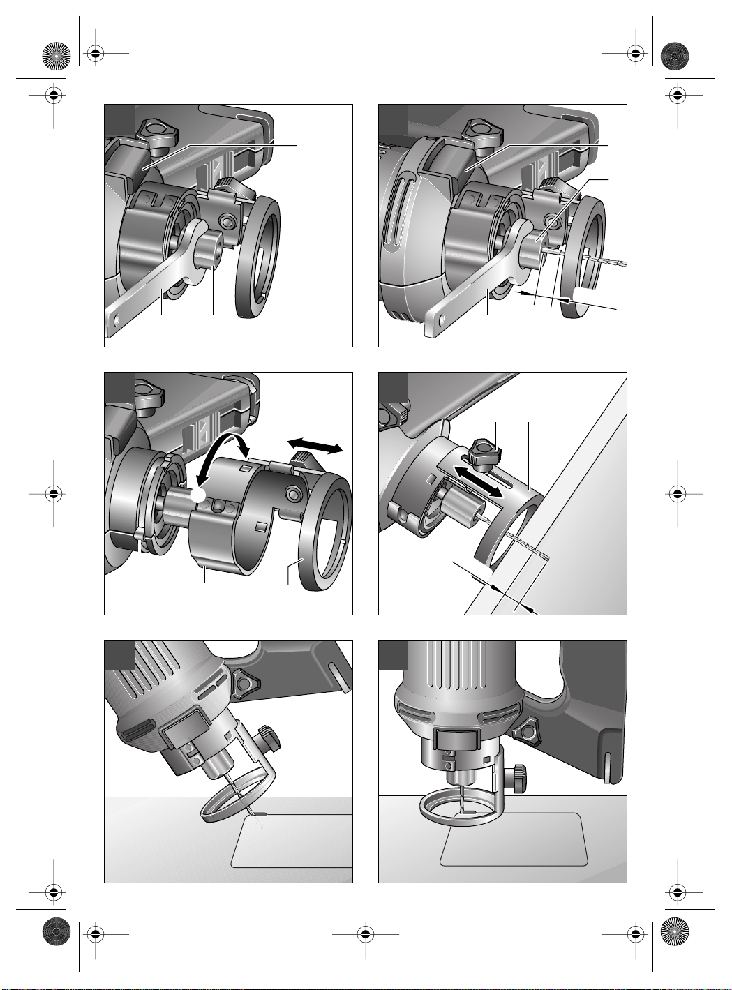
A
Spindellock-Taste 3 drücken und Überwurfmutter
rastet. Überwurfmutter
(SW 16)
Entsprechende Spannzange
mutter
und von Hand ca. 5 Umdrehungen festschrauben.
3 mm des Werkzeugschaftes sichtbar sind.
Spindellock-Taste
2 610 998 773 • TMS • 10.08.00
ter
hen.
drehen, bis die Spindellock-Taste ein-
abschrauben.
einsetzen, Überwurfmutter 4 aufsetzen
B
Schneidewerkzeug einschieben, bis noch
mit dem Gabelschlüssel (SW 16) 2 festzie-
Der Schaftdurchmesser des Schneidewerkzeuges muss mit dem angegebenen Durchmesser der Werkzeugaufnahme übereinstimmen.
Die verwendeten Schneidewerkzeuge müssen
für die Höchstdrehzahl des Gerätetyps zugelassen sein.
mit Gabelschlüssel
in die Überwurf-
drücken und Überwurfmut-
Verstellbare Fußplatte demontieren/montieren/einstellen
Fußplatte 7 nur mit ausgebautem
☞
Schneidewerkzeug wechseln bzw. verstellen.
Demontieren:
C
Fußplatte 7 bis zum spürbaren Anschlag ge-
gen den Uhrzeigersinn
drehen und abziehen.
Montieren:
C
Fußplatte 7 mit der Ausbuchtung 12 auf die
Blechnase
drehen, bis die Fußplatte 7 mit der Raste in der
Ausbuchtung hörbar einrastet. Nicht über diese
Raste hinausdrehen.
Schnitttiefe einstellen:
D
stellen, dass das Schneidewerkzeug mind. 6 mm
aus dem zu schneidenden Material herausragt.
Rändelschraube
13 schieben und im Uhrzeigersinn II
Rändelschraube 6 lösen. Fußplatte 7 so ein-
festschrauben.
Inbetriebnahme
Netzspannung beachten: Die Spannung der
Stromquelle muss mit den Angaben auf dem Typschild des Gerätes übereinstimmen. Mit 230 V
gekennzeichnete Geräte können auch an 220 V
betrieben werden.
Mit 100 V gekennzeichnete Geräte können auch
an 115 V betrieben werden.
Einschalten: Ein-/Ausschalter 9 herausschie-
Ausschalten: Ein-/Ausschalter 9 in
ben.
Position
OFF schieben.
Deutsch - 2

Euro • Printed in USA • BA 2 610 998 773 • Rotocut • D • OSW 08/00
Rotocut - Buch Seite 3 Dienstag, 15. August 2000 10:23 10
Staub-/Späneabsaugung
Beim Arbeiten entstehender
Staub ist gesundheitsschädlich.
Staub-/Späneabsaugung verwenden und Staubschutzmaske
tragen.
Die Staub-/Späneabsaugung verhindert größere Verschmutzungen, hohe Staubbelastung der
Atemluft und erleichtert die Entsorgung der Späne bzw. des
Staubes.
Das Gerät kann direkt an die Steckdose eines
Bosch-Allzwecksaugers mit Fernstarteinrichtung
angeschlossen werden. Dieser wird beim Einschalten des Gerätes automatisch gestartet.
Der Staubsauger muss für den zu bearbeitenden
Werkstoff geeignet sein.
Beim Absaugen von besonders gesundheitsgefährdenden, krebserzeugenden, trockenen Stäuben ist ein Spezialsauger zu verwenden.
Bosch bietet geeignete Sauger für alle zu bearbeitenden Werkstoffe an.
Zum Absaugen kann der Ø 19-mm-Absaug-
schlauch (1 610 793 002 oder 2 600 793 009 siehe Zubehör) direkt am Absaugstutzen 8 angeschlossen werden. Bei vertikalen Flächen Gerät
so halten, dass der Absaugschlauch nach unten
zeigt.
Bei längerem Bearbeiten von Holz oder bei gewerblichem Einsatz an Materialien, bei denen gesundheitsgefährdende Stäube entstehen, ist das
Gerät an eine geeignete externe
tung anzuschließen.
In Deutschland werden für Holzstäube auf Grund
TRGS 553 geprüfte Absaugeinrichtungen gefordert, die interne Absaugeinrichtung darf im gewerblichen Bereich nicht verwendet werden. Für
andere Materialien muss der gewerbliche Betreiber die speziellen Anforderungen mit der zuständigen Berufsgenossenschaft klären.
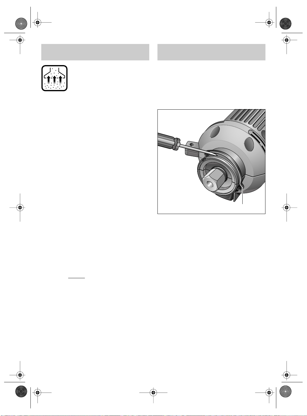
Absaugvorrich-
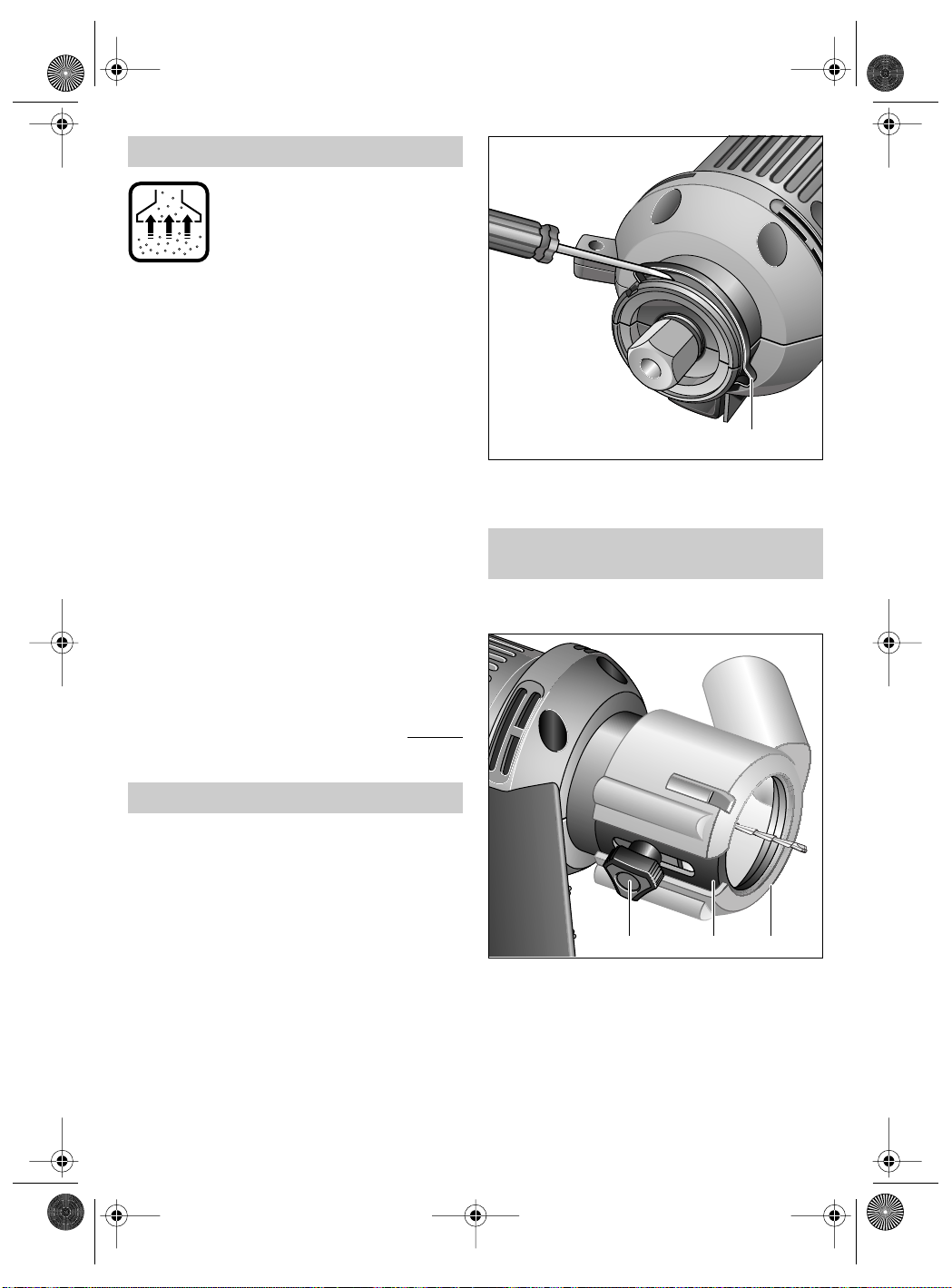
Federring 21 mit Hilfe eines Schraubendrehers
aushebeln.
Absaugstutzen montieren/
demontieren
■ Vor allen Arbeiten am Gerät Netzstecker
21
ziehen.
2 610 998 773 • TMS • 10.08.00
Federring entfernen
■ Das Öffnen des Gehäuses darf nur von au-
torisiertem Fachpersonal durchgeführt
werden!
■ Vor allen Arbeiten am Gerät Netzstecker
ziehen.
Zum Öffnen des Gehäuses Federring 21 entfer-
nen.
Deutsch - 3
8 7 6
Montieren:
Absaugstutzen 8 mit dem Spalt zur Rändel-
schraube 6 zeigend auf die Fußplatte 7 schieben,
bis er hörbar einrastet.
Demontieren:
Absaugstutzen 8 am Spalt etwas aufbiegen und
von der Fußplatte 7 abziehen.
Euro • Printed in USA • BA 2 610 998 773 • Rotocut • D • OSW 08/00
Rotocut - Buch Seite 4 Dienstag, 15. August 2000 10:23 10
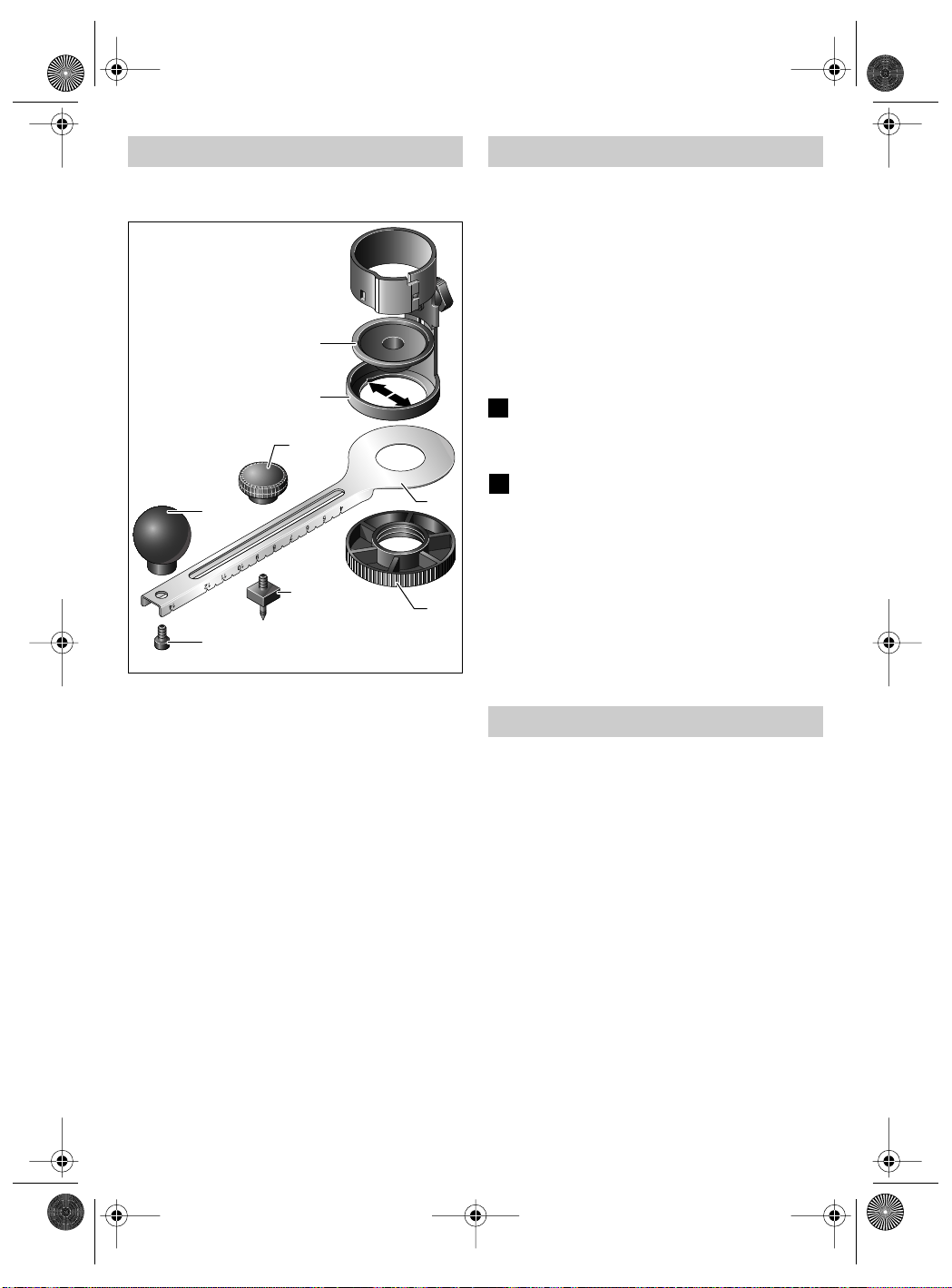
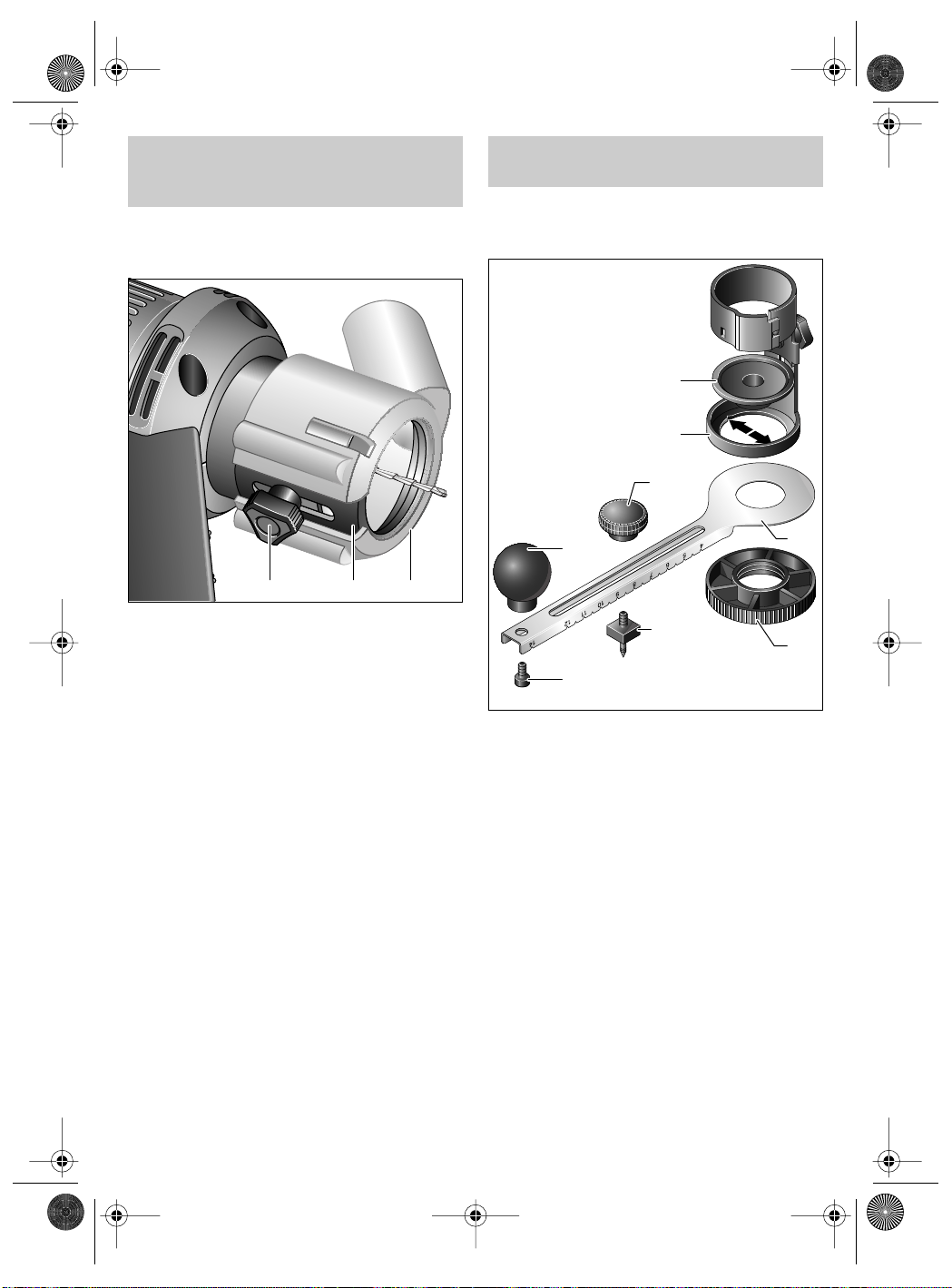
Kreisschneider montieren
■ Vor allen Arbeiten am Gerät Netzstecker
ziehen.
14
7
20
19
17
18
– Zunächst Schneidewerkzeug demontieren.
2 610 998 773 • TMS • 10.08.00
– Zur Montage des Kreisschneiders 11 (Zube-
hör) empfehlen wir, die Fußplatte 7 abzuneh-
men.
– Gewindeplatte 14 mit den Führungsnasen in
die Aussparungen (Pfeile) der Fußplatte 7 einlegen.
– Kreisschneidearm 15, Skalierung nach unten,
mit der Rundmutter 16 an die Gewinde-
platte 14 (in Fußplatte 7) anschrauben.
– Einstechdorn 17 in die Führung einlegen, er-
forderlichen Durchmesser einstellen und mit
der Feststellmutter 20 fixieren. Angaben auf
dem Kreisschneidearm 15 entsprechen dem
Durchmesser des zu schneidenden Kreises.
– Griff 19 mit der Schraube 18 am Kreisschnei-
dearm 15 fixieren. Für die Benutzung des ma-
ximalen Kreisdurchmessers kann auch der
Griff 19 zum Kontern des Einstechdorns 17
genutzt werden.
– Fußplatte 7 mit angesetztem Kreisschnei-
der 11 montieren.
– Schneidewerkzeug einsetzen.
15
16
Arbeitshinweise
■ Arbeiten Sie immer im Uhrzeigersinn.
■ Das Gerät kann nur zum Schneiden bis zu
einer Materialstärke von 25 mm verwendet
werden.
■ Nicht mit Spindellock-Taste abbremsen.
■ Spindel und Fußplatte stets sauberhalten.
Je nach zu bearbeitenden Materialien sind entsprechende Schneidewerkzeuge zu verwenden.
Ausschnitte jeder Form sind ohne vorzubohren
durch Einstechen des Schneidewerkzeugs bei
laufender Maschine möglich.
E
Gerät mit der Kante der Fußplatte in etwa
45°-Winkel auf das Werkstück aufsetzen und einschalten. Schneidewerkzeug langsam in das
Werkstück eintauchen.
Nach Erreichen der erforderlichen Schnitt-
F
tiefe Gerät wieder in normale Arbeitsstellung bringen, so dass die Fußplatte ganzflächig aufliegt.
Entlang der Schnittlinie weiterschneiden.
Nach dem Arbeitsvorgang, Gerät erst ausschalten und anschließend aus dem Schnitt ziehen.
Um empfindliche Oberflächen der Werkstücke,
z. B. Keramik, zu schützen, ist der Gleitschuh 10
(Zubehör) auf die Fußplatte 7 aufzusetzen.
Der Gleitschuh 10 (Zubehör) kann auch als Parallelanschlag für gerade Schnitte benutzt werden.
Wartung und Reinigung
■ Vor allen Arbeiten am Gerät Netzstecker
ziehen.
Gerät und Lüftungsschlitze stets sauber
☞
halten, um gut und sicher zu arbeiten.
Werkzeugaufnahme und Fußplatte bei jedem Wechsel säubern.
Sollte das Gerät trotz sorgfältiger Herstellungsund Prüfverfahren einmal ausfallen, ist die Reparatur von einer autorisierten Kundendienststelle
für Bosch-Elektrowerkzeuge ausführen zu lassen.
Bei allen Rückfragen und Ersatzteilbestellungen
bitte unbedingt die 10-stellige Bestellnummer laut
Typenschild des Gerätes angeben.
Deutsch - 4
Euro • Printed in USA • BA 2 610 998 773 • Rotocut • D • OSW 08/00
Rotocut - Buch Seite 5 Dienstag, 15. August 2000 10:23 10
Garantie
Für Bosch-Geräte leisten wir Garantie gemäß
den gesetzlichen/länderspezifischen Bestimmungen (Nachweis durch Rechnung oder Lieferschein).
Schäden, die auf natürliche Abnützung, Überlastung oder unsachgemäße Behandlung zurückzuführen sind, bleiben von der Garantie ausgeschlossen.
Beanstandungen können nur anerkannt werden,
wenn Sie das Gerät unzerlegt an den Lieferer
oder an eine Bosch-Kundendienstwerkstätte für
Druckluft- oder Elektrowerkzeuge senden.
Umweltschutz
Rohstoffrückgewinnung statt Müllentsorgung
Gerät, Zubehör und Verpackung sollten einer umweltgerechten Wiederverwertung zugeführt werden.
Diese Anleitung ist aus chlorfrei gefertigtem Recycling-Papier hergestellt.
Zum sortenreinen Recycling sind Kunststoffteile
gekennzeichnet.
In Deutschland sind nicht mehr gebrauchsfähige
Geräte zum Recycling beim Handel abzugeben
oder (ausreichend frankiert) direkt einzuschicken
an:
Recyclingzentrum Elektrowerkzeuge
Osteroder Landstraße 3
37589 Kalefeld
Service und Kundenberater
Deutschland
Robert Bosch GmbH
Servicezentrum Elektrowerkzeuge
Zur Luhne 2
D-37589 Kalefeld
✆ Service: ........................................ 01 80 - 3 35 54 99
........................................................... (0 55 53) 20 22 37
Fax
✆ Kundenberater:....................... 01 80 - 3 33 57 99
Österreich
ABE Service GmbH
Jochen-Rindt-Straße 1
A-1232 Wien
✆ Service: ............................................ (02 22) 61 03 80
........................................................ (02 22) 61 03 84 91
Fax
✆ Kundenberater:.................(02 22) 7 97 22 30 20
Schweiz
Robert Bosch AG
Kundendienst Elektrowerkzeuge
Industriestrasse 31
CH-8112 Otelfingen
✆ Service: .............................................. (01) 8 47 16 16
✆ Kundenberater:........Grüne Nr. 0 800 55 11 55
2 610 998 773 • TMS • 10.08.00
Deutsch - 5
Konformitätserklärung
Wir erklären in alleiniger Verantwortung, dass
dieses Produkt mit den folgenden Normen oder
normativen Dokumenten übereinstimmt:
EN 50 144, HD 400 gemäß den Bestimmungen
der Richtlinien 89/336/EWG, 98/37/EG.
Dr. Gerhard Felten Dr. Eckerhard Strötgen
Robert Bosch GmbH, Geschäftsbereich Elektrowerkzeuge
Änderungen vorbehalten
Euro • Printed in USA • BA 2 610 998 773 • Rotocut • GB • OSW 08/00
Rotocut - Buch Seite 1 Dienstag, 15. August 2000 10:23 10
Tool Specifications
Rotocut
Part number 0 601 638 1..
Rated power* 450 W
No-load speed 30 000 RPM
Collet chucks Ø 3.2 mm (1/8")
Collet chucks Ø 6.4 mm (1/4")
Weight (without optional
extras) approx.
1.2 kg
Safety class / II
* The values given are valid for nominal voltages [U] of 230/
240 V. For lower voltages and models for specific countries,
these values can vary.
Noise/Vibration Information
Measured values determined according to
EN 50 144.
The A-weighted noise levels of the machine are
typically: sound pressure level: 79 dB (A); sound
power level: 92 dB (A).
Wear ear protection!
The typical hand/arm vibration is below 2.5 m/s
Machine Elements
For Your Safety
Working safely with this machine
is possible only when the operating and safety information are
read completely and the instructions contained therein are
strictly followed. In addition, the
general safety instructions in the
enclosed booklet must be followed. Before using for the first
time, ask for a practical demonstration.
Pull the mains plug.
If the mains cable is damaged or cut
through while working, do not touch
the cable but immediately pull the
mains plug. Never use the machine
with a damaged cable.
Damage.
When cutting in corners and walls,
examine the place to be treated beforehand, making sure that there
are no concealed electric cables,
2
.
gas or water conduits, e.g. use a
metal detector.
Wear protective glasses and ear
protection.
1 Auxiliary handle
2 610 998 773 • TMS • 10.08.00
2 Open-ended spanner (SW 16)
3 Spindle lock button
4 Screwed cap
5 Collet chuck 3.2 mm (1/8")
Collet chuck 6.4 mm (1/4")
6 Knurled screw
7 Adjustable base plate
8 Extractor connection (for flexible tube
Ø 19 mm)
9 On/Off switch
10 Adjustable foot plate
11 Circular cutter
12 Hollow
13 Metal projection
Not all of the accessories illustrated or described are
included as standard delivery.
Wear a dust protection mask.
Danger of injury.
Sharp application tool.
■ When working with the machine, always hold it
firmly with both hands and provide for a secure
stance.
■ Insert the mains plug only when the machine is
switched off.
■ Always direct the cable to the rear away from
the machine.
■ Do not work with materials containing asbestos.
■ Keep hands away from the rotating cutting tool.
English - 1
Euro • Printed in USA • BA 2 610 998 773 • Rotocut • GB • OSW 08/00
Rotocut - Buch Seite 2 Dienstag, 15. August 2000 10:23 10
■ Apply the machine to the workpiece only when
switched on.
■ Always switch off the machine and allow to
come to a stop before placing it down.
■ Bosch is only able to ensure perfect functioning
of the machine if the original accessories intended for it are used.
Intended Use
The unit is designed to cut gypsum, wood, plexiglass, plastics and soft wall tiles.
Changing the Tool
■ Before any work on the machine itself, pull
the mains plug.
A
Press the spindle lock button 3 and turn the
union nut 4 until the spindle lock button notches.
Unscrew the union nut 4 using the open-end
spanner (SW 16) 2.
Insert the corresponding collet chuck 5 in the union nut 4, mount the union nut 4 and screw it on
tightly by hand through approx. 5 turns.
B
Push in the cutting tool, leaving 3 mm of the
tool shaft still visible.
Press the spindle lock button 3 and tighten the
union nut 4 firmly using the open-end spanner
(SW 16) 2.
■ The shaft diameter of the cutting tool must
agree with the stipulated diameter of the tool
carrier.
■ The cutting tools used must be approved for
the highest speed for this machine type.
Dismounting/Mounting/Setting
the Adjustable Base Plate
Only change or adjust the base plate 7
☞
once the cutting tool has been removed.
Dismounting:
C
Turn the base plate 7 anti-clockwise I until it is
felt to stop, and pull off.
Mounting:
C
Push the base plate 7 with the hollow 12 over
the metal projection 13 and turn anti-clockwise II
until the base plate 7 with the projection is clearly
heard to notch in the hollow. Do not turn beyond
this projection.
Adjusting the Cutting Depth:
D
Loosen the knurled screw 6. Adjust the base
plate 7 such that the cutting tool projects at least
6 mm from the material to be cut.
Tighten the knurled screw 6 firmly.
Initial Operation
Check for correct mains voltage: The voltage
of the power source must agree with the voltage
specified on the nameplate of the machine.
Equipment marked with 230 V can also be connected to 220 V.
Machines marked 100 V can also be connected
to 115 V.
Switching on: Push out On/Off switch 9.
Switching off: Push the On/Off switch 9 to the
OFF position.
2 610 998 773 • TMS • 10.08.00
English - 2
Euro • Printed in USA • BA 2 610 998 773 • Rotocut • GB • OSW 08/00
Rotocut - Buch Seite 3 Dienstag, 15. August 2000 10:23 10
Sawdust Vacuuming
The dust produced while working
is injurious to health. Remove
the dust and shavings by vacuuming and wear a protective
dust-proof mask.
Vacuuming the dust/sawdust
prevents it from accumutating
and causing a high dust concentration of the air brealned in and
facilitates disposing of the dust/
sawdust.
The machine can be plugged directly into the receptacle of a Bosch general-purpose vac with remote starting control. The vac starts automatically
when the Rotocut is switched on.
The vacuum cleaner must be suitable for the material to be worked.
When vacuuming dry dust that is especially detrimental to health or carcinogenic, use a special
vacuum cleaner.
Bosch offers suitable vacuum cleaners for all materials to be worked.
For vacuuming, the 19 mm Ø suction hose
(1 610 793 002 or 2 600 793 009 - see accessories) can be connected directly to extractor connection 8. For vertical surfaces, hold the machine
such that the suction hose is directed downwards.
When working with wood for a longer period and
during commercial treatment of materials that
2 610 998 773 • TMS • 10.08.00
produce dust that is detrimental to health, the machine is to be connected to a suitable external
dust extraction device.
21
Lever off the spring washer 21 using a screw-
driver.
Mounting/Dismounting the
Extractor Connection
■ Before any work on the machine itself, pull
the mains plug.
Remove the spring washer
■ The housing may only be opened by au-
thorised qualified personnel!
■ Before any work on the machine itself, pull
the mains plug.
To open the housing, remove spring washer 21.
8 7 6
Mounting:
Push the extractor connection 8 with the open slit
pointing to the knurled screw 6 onto the base
plate 7 until it is heard to notch.
Dismounting:
Ease the extractor connection 8 open a little at
the open slit and pull it off the base plate 7.
English - 3
Euro • Printed in USA • BA 2 610 998 773 • Rotocut • GB • OSW 08/00
Rotocut - Buch Seite 4 Dienstag, 15. August 2000 10:23 10
Mounting the Circular Cutter
■ Before any work on the machine itself, pull
the mains plug.
14
7
20
19
15
17
16
18
– Firstly, dismount the cutting tool.
– For mounting the circular cutter 11 (accessory)
we recommend taking off the base plate 7.
– Insert the threaded plate 14 with the guiding
projections into the notches (arrows) on the
base plate 7.
– Screw the circular-cutting arm 15, scale facing
downwards, to the threaded plate 14 (in the
base plate 7) with the round nut 16.
– Insert the punching pin 17 in the guide, set the
required diameter and secure using the lock
nut 20. The specifications on the circular-cut-
ting arm 15 correspond with the diameter of the
circle to be cut.
– Secure the handle 19 to the circular-cutting
arm 15 using screw 18. When using the maxi-
mum circle diameter, the handle 19 can also
serve in place of the lock nut for securing the
punching pin 17.
– Assemble the base plate 7 with the circular cut-
ter 11 applied.
– Insert the cutting tool.
Operating Instructions
■ Always work in a clockwise direction.
■ The machine can only be used for cutting
material up to a thickness of 25 mm.
■ Do not brake it using the spindle lock but-
ton.
■ Always keep the spindle and base plate
clean.
The correct cutting tools should be used to suit
the material to be treated.
Cut-outs of any form are possible without drilling
in advance, by punching with the cutting tool while
the machine is running.
E
Position the machine with the edge of the
base plate at an angle of about 45° to the workpiece and switch on. Slowly lower the machine
into the work-piece.
After reaching the required cutting depth, turn
F
the machine to its normal working position again
with the entire base plate contacting the surface.
Continue to cut along the cutting line.
After completing the cut, switch off the machine
first and then pull it out of the cut.
To protect susceptible work-piece surfaces, e.g.
ceramics, the adjustable foot plate 10 (acces-
sory) should be mounted on the base plate 7.
The adjustable foot plate 10 (accessory) can also
be used as a parallel stop plate for straight cuts.
Maintenance and Cleaning
■ Before any work on the machine itself, pull
the mains plug.
For safe and proper working, always keep
☞
the machine and the ventilation slots clean.
Clean the tool carrier and base plate after
every tool change.
If the machine should fail despite the rigorous
manufacturing and testing procedures, repair
should be carried out by an authorised after-sales
service centre for Bosch power tools.
In all correspondence and spare parts orders,
please always include the 10-digit order number
given on the nameplate of the machine.
2 610 998 773 • TMS • 10.08.00
English - 4
Euro • Printed in USA • BA 2 610 998 773 • Rotocut • GB • OSW 08/00
Rotocut - Buch Seite 5 Dienstag, 15. August 2000 10:23 10
WARNING! Important instructions for connecting a new 3-pin plug to the 2 wire cable.
The wires in the cable are coloured according to
the following code:
strain relief
To be fitted
live = brown
neutral = blue
connect the blue or brown wire to the earth
Do not
by qualified
professional only
terminal of the plug.
Important: If for any reason the moulded plug is
removed from the cable of this machine it must be
disposed of safely.
Guarantee
We guarantee Bosch appliances in accordance
with statutory/country-specific regulations (proof
of purchase by invoice or delivery note).
Damage attributable to normal wear and tear,
overload or improper handling will be excluded
from the guarantee.
In case of complaint please send the machine,
undismantled, to your dealer or the Bosch Service Centre for electric power tools.
Environmental Protection
2 610 998 773 • TMS • 10.08.00
Recycle raw materials instead of disposing as
waste.
The machine, accessories and packaging should
be sorted for environmental-friendly recycling.
These instructions are printed on recycled paper
manufactured without chlorine.
The plastic components are labelled for categorized recycling.
Service and
Customer Assistance
Great Britain
Robert Bosch Ltd. (B.S.C.)
P.O. Box 98
Broadwater Park
North Orbital Road
Denham-Uxbridge
GB-Middlesex UB 9 5HJ
✆ Service........................................ (0 18 95) 83 87 82
✆ Advice line................................ (0 18 95) 83 87 91
......................................................... (0 18 95) 83 87 89
Fax
Ireland
Beaver Distribution Ltd.
Greenhills Road
IRL-Tallaght-Dublin 24
✆ Service................................................ (01) 45 15 211
................................................................. (01) 45 17 127
Fax
Australia
Robert Bosch Australia L.t.d.
RBAU/SPT2
1555 Centre Road
P.O. Box 66 Clayton
AUS-3168 Clayton/Victoria
✆ .................................................................. 1 800 804 777
.................................................................. 1 800 819 520
Fax
New Zealand
Robert Bosch Limited
14-16 Constellation Drive
Mairangi Bay
Auckland
New Zealand
✆ ................................................................. (09) 47 86 158
................................................................. (09) 47 82 914
Fax
Declaration of Conformity
We declare under our sole responsibility that this
product is in conformity with the following standards or standardisation documents: EN 50 144,
HD 400 according to the provisions of the directives 89/336/EEC, 98/37/EC.
Dr. Gerhard Felten Dr. Eckerhard Strötgen
Robert Bosch GmbH, Geschäftsbereich Elektrowerkzeuge
Subject to change without notice
English - 5
Euro • Printed in USA • BA 2 610 998 773 • Rotocut • F• OSW 08/00
Rotocut - Buch Seite 1 Dienstag, 15. August 2000 10:23 10
Caractéristiques techniques
Rotocut
Référence 0 601 638 1..
Puissance absorbée* 450 W
Régime à vide 30 000 min
-1
Ø des pinces de serrage 3,2 mm (1/8")
Ø des pinces de serrage 6,4 mm (1/4")
Poids (sans accessoires) env. 1,2 kg
Classe de protection / II
* Ces indications sont valables pour des tensions nominales
de [U] 230/240 V. Elles peuvent varier pour des tensions
plus basses ainsi que pour des versions spécifiques à certains pays.
Bruits et vibrations
Valeurs de mesure obtenues conformément à la
norme européenne 50 144.
Les mesures réelles (A) des niveaux sonores de
la machine sont : Intensité de bruit 79 dB (A). Niveau de bruit 92 dB (A).
Munissez-vous d’une protection acoustique !
La vibration de l’avant-bras est en-dessous de
2
2,5 m/s
.
Eléments de la machine
1 Poignée supplémentaire
2 Clé à fourche (Taille d’ouverture 16)
3 Touche de blocage de la broche
4 Ecrou-raccord
5 Pince de serrage 3,2 mm (1/8"))
Pince de serrage 6,4 mm (1/4")
6 Vis moletée
7 Plaque de base réglable
8 Tubulure d’évacuation des poussières (pour
tuyau Ø 19 mm)
9 Interrupteur Marche/Arrêt
10 Patin de glissage
11 Dispositif pour coupes circulaires
12 Courbure
13 Nez en tôle
Les accessoires reproduits ou décrits ne sont pas
forcément fournis avec la machine.
Français - 1
Pour votre sécurité
Pour travailler sans risque avec
cet appareil, lire intégralement au
préalable les instructions d’utilisation et les remarques concernant la sécurité. Respecter scrupuleusement les indications et
les consignes qui y sont données. En plus, il convient de respecter les consignes d’ordre général touchant à la sécurité qui
sont définies dans le cahier cijoint. Avant la première mise en
service, laisser quelqu’un connaissant bien cet appareil vous
indiquer la façon de s’en servir.
Extraire la fiche du cordon d’alimentation hors de la prise électrique.
Si le câble d’alimentation électrique
est endommagé ou se rompt pendant le travail, ne pas y toucher. Retirer immédiatement la fiche du câble d’alimentation de la prise de
courant. Ne jamais utiliser un appareil dont le cordon d’alimentation est
endommagé.
Endommagements.
Avant de couper dans les murs et
dans les coins, contrôler l’endroit de
travail, par exemple à l’aide d’un détecteur de métaux, afin de détecter
la position des conduites électriques, de gaz ou d’eau encastrées.
Porter des lunettes de sécurité et
une protection acoustique.
Porter un masque respiratoire.
Risques de blessures.
Outil de travail à bords tranchants.
■ Pendant le travail avec cet appareil, le tenir
toujours fermement avec les deux mains.
Adopter une position stable et sûre.
■ Ne brancher l’appareil que si celui-ci est en position « Arrêt ».
2 610 998 773 • TMS • 10.08.00
Euro • Printed in USA • BA 2 610 998 773 • Rotocut • F• OSW 08/00
Rotocut - Buch Seite 2 Dienstag, 15. August 2000 10:23 10
■ Toujours ramener les câbles à l’arrière de l’appareil.
■ Ne jamais travailler de matériau contenant de
l’amiante.
■ Tenir les mains à l’écart des outils de coupe en
rotation.
■ N’appliquer l’appareil contre la pièce à usiner
que lorsque celui-ci est en marche.
■ Toujours déconnecter l’appareil et le laisser ralentir jusqu’à l’arrêt avant de le déposer.
■ Bosch ne peut garantir un fonctionnement impeccable que si les accessoires Bosch d’origine prévus pour cet appareil sont utilisés.
Utilisation conformément à la
destination de l’appareil
L’appareil est conçu pour le découpage du plâtre,
du bois, du plexiglas, des matières plastiques et
du carrelage mural tendre.
Changement de l’outil
■ Avant toute intervention sur l’appareil proprement dit, toujours retirer la fiche du câble d’alimentation de la prise de courant.
A
Appuyer sur la touche de blocage de la broche 3 et tourner l’écrou-raccord 4 jusqu’à ce que
la touche de blocage de la broche s’encliquette.
Dévisser l’écrou-raccord 4 à l’aide de la clé à
2 610 998 773 • TMS • 10.08.00
fourche (taille d’ouverture 16) 2.
Monter la pince de serrage correspondante 5
dans l’écrou-raccord 4, positionner l’écrou-rac-
cord 4 et visser environ 5 tours à la main.
B
Introduire l’outil de coupe jusqu’à ce que
3 mm de la tige de l’outil soit encore visible.
Appuyer sur la touche de blocage de la broche 3
et serrer l’écrou-raccord 4 à l’aide de la clé à fourche (taille d’ouverture 16) 2.
■ Le diamètre de la tige de l’outil de coupe doit
coïncider avec le diamètre indiqué du porteoutil.
■ Les outils de coupe utilisés doivent être homo-
logués pour la vitesse de rotation maximale du
type d’appareil.
Démontage/montage/réglage de
la plaque de base réglable
Ne changer ou déplacer la plaque de
☞
base 7 que si l’outil de coupe est démonté.
Démontage :
C
Tourner la plaque de base 7 dans le sens inverse des aiguilles d’une montre I jusqu’à ce que
vous entendiez un déclic perceptible et la retirer.
Montage :
C
Positionner la plaque de base 7 en plaçant la
courbure 12 sur le nez 13 et tourner dans le sens
des aiguilles d’une montre II jusqu’à ce que la plaque de base 7 s’encliquette de manière perceptible avec le cran dans la courbure. Ne pas dépasser ce cran.
Réglage de la profondeur de coupe:
D
Desserrer la vis moletée 6. Régler la plaque
de base 7 de sorte que l’outil de coupe dépasse
le matériau à découper de 6 mm au minimum.
Serrer la vis moletée 6.
Mise en service
Tenir compte de la tension du secteur : La tension de la source de courant doit correspondre
aux indications figurant sur la plaque signalétique
de l’appareil. Les appareils fonctionnant sous
230 V peuvent également être exploités sous
220 V.
Les appareils marqués 100 V peuvent également
être mis en service sous 115 V.
Mise en
fonctionnement : Pousser l’interrupteur
Arrêt : Pousser l’interrupteur
Marche/Arrêt 9 sur la
position ON.
Marche/Arrêt 9 sur la
position OFF.
Français - 2
Euro • Printed in USA • BA 2 610 998 773 • Rotocut • F• OSW 08/00
Rotocut - Buch Seite 3 Dienstag, 15. August 2000 10:23 10
Aspiration de poussières/
de copeaux
Les poussières dégagées lors
des opérations d’usinage sont
dangereuses pour la santé. Utiliser un dispositif d’aspiration des
poussières et des copeaux, porter également un masque de protection contre les poussières.
L’aspiration de poussières/de
copeaux sert à empêcher un encrassement important, une dégradation de l’air due à des poussières, et à améliorer l’évacuation des copeaux ou des
poussières.
L’appareil peut être branché directement sur la
prise d’un aspirateur universel Bosch avec commande à distance. L’aspirateur se met automatiquement en marche dès que l’appareil est mis en
fonctionnement.
L’aspirateur doit être approprié au matériau à travailler.
Pour l’aspiration de poussières particulièrement
nuisibles à la santé, cancérigènes ou sèches, utiliser des aspirateurs spéciaux.
Bosch vous offre des aspirateurs appropriés à
tous les matériaux à travailler.
Il est possible de raccorder directement un tuyau
flexible de 19 mm de diamètre (1 610 793 002 ou
2 600 793 009 - voir accessoires) sur la tubulure
d’évacuation des poussières 8. Lors du travail sur
des surfaces verticales, tenir l’appareil de sorte
que le tuyau d’aspiration soit dirigé vers le bas.
Lors de travaux prolongés sur du bois ou lors
d’une utilisation industrielle sur des matériaux
produisant des poussières nuisibles à la santé, il
convient de raccorder l’appareil à un dispositif
d’aspiration externe
approprié.
Démontage de l’anneau
élastique
■ L’appareil ne doit être ouvert que par du
personnel spécialisé autorisé !
■ Avant toute intervention sur l’appareil pro-
prement dit, toujours retirer la fiche du câble d’alimentation de la prise de courant.
Pour ouvrir le carter, enlever l’anneau élastique 21.
21
Faire sortir l’anneau élastique 21 à l’aide d’un
tournevis.
2 610 998 773 • TMS • 10.08.00
Français - 3
Euro • Printed in USA • BA 2 610 998 773 • Rotocut • F• OSW 08/00
Rotocut - Buch Seite 4 Dienstag, 15. August 2000 10:23 10
Montage/démontage de la
tubulure d’évacuation des
poussières
■ Avant toute intervention sur l’appareil pro-
prement dit, toujours retirer la fiche du câble d’alimentation de la prise de courant.
8 7 6
Montage :
Monter la tubulure d’évacuation des poussières 8
sur la plaque de base 7, la fente montrant vers la
vis moletée 6, jusqu’à ce qu’elle s’encliquette de
2 610 998 773 • TMS • 10.08.00
manière perceptible.
Démontage :
Ecarter légèrement la tubulure d’évacuation 8 au
niveau de la fente et la retirer de la plaque de
base 7.
Montage du dispositif pour
coupes circulaires
■ Avant toute intervention sur l’appareil pro-
prement dit, toujours retirer la fiche du câble d’alimentation de la prise de courant.
14
7
20
19
15
17
16
18
– D’abord démonter l’outil de coupe.
– Pour monter le dispositif pour coupes circulai-
res 11 (accessoire), nous recommandons
d’enlever la plaque de base 7.
– Monter la plaque filetée 14 en veillant à ce que
les nez de guidage prennent dans les encoches de la plaque de base 7 (voir flèches).
– Visser le bras de coupe circulaire 15 la gra-
duation vers le bas, sur la plaque filetée 14 (se
trouvant dans la plaque de base 7) au moyen
de l’écrou rond 16.
– Positionner le tourillon 17 dans le guidage, ré-
gler le diamètre nécessaire et fixer avec
l’écrou de blocage 20. Les indications se trouvant sur le bras de coupe circulaire 15 correspondent au diamètre du cercle à découper.
– Fixer la poignée 19 sur le bras de coupe circu-
laire 15 au moyen de la vis 18. Afin d’appliquer
le diamètre maximal, la poignée 19 peut également être utilisée pour bloquer le tourillon 17.
– Monter la plaque de base 7 munie du dispositif
pour coupes circulaires 11.
– Monter l’outil de coupe.
Français - 4
Euro • Printed in USA • BA 2 610 998 773 • Rotocut • F• OSW 08/00
Rotocut - Buch Seite 5 Dienstag, 15. August 2000 10:23 10
Instructions d’utilisation
■ Travailler toujours dans le sens des
aiguilles d’une montre.
■ L’appareil ne peut être utilisé que pour cou-
per des matériaux dont l’épaisseur est inférieure à 25 mm.
■ Ne pas freiner les parties en rotation à l’aide
de la touche de blocage de la broche.
■ Toujours maintenir propres la broche et la
plaque de base.
Les outils de coupe doivent être choisis en fonction du matériau à travailler.
Il est possible d’effectuer des coupes de toute
sorte sans avoir percé préalablement, en plongeant l’outil de coupe dans le matériau pendant
que la machine est en marche.
E
Positionner l’appareil avec le bord de la plaque de base formant un angle de 45° sur la pièce
à travailler et mettre l’appareil en fonctionnement.
Plonger lentement l’outil de coupe dans la pièce à
travailler.
Une fois la profondeur de coupe nécessaire
F
atteinte, remettre l’appareil dans sa position de
travail normale de sorte que la plaque de base repose de toute sa surface sur la pièce. Continuer à
couper le long du tracé.
Une fois la coupe terminée, arrêter l’appareil et le
retirer du tracé seulement à ce moment-là.
Afin de protéger les surfaces fragiles des pièces,
p. ex. en céramique, contre des rayures, monter
le patin de glissage 10 (accessoire) sur la plaque
de base 7.
Le patin de glissage 10 (accessoire) peut également être utilisé comme butée parallèle pour des
coupes droites.
Nettoyage et entretien
■ Avant toute intervention sur l’appareil pro-
prement dit, toujours retirer la fiche du câble d’alimentation de la prise de courant.
Pour obtenir un travail sûr et satisfaisant,
☞
nettoyer régulièrement l’appareil ainsi que
ses ouïes de refroidissement. Nettoyer le
porte-outil et la plaque de base à chaque
changement d’outil.
Si, malgré tous les soins apportés à la fabrication
et au contrôle de l’appareil, celui-ci devait avoir un
défaut, la réparation ne doit être confiée qu’à une
station de service après-vente agréée pour
outillage Bosch.
Pour toute demande de renseignements ou commande de pièces de rechange, nous préciser impérativement le numéro de référence à dix chiffres de la machine.
Garantie
Les appareils Bosch sont garantis conformément
aux dispositions légales/nationales (contre
preuve d’achat, facture ou bordereau de livraison). Cette garantie implique le remplacement
gratuit des pièces défectueuses. En tout état de
cause s’applique la garantie légale couvrant toutes les conséquences des défauts ou vices cachés. (Articles 1641 et suivants du Code civil.)
Cette garantie correspond à un emploi normal de
l’outil et exclut les avaries dues à un mauvais
usage, à un entretien défectueux ou à l’usure normale. Le jeu de la garantie ne peut en aucun cas
donner lieu à des dommages et intérêts.
Pour que cette garantie soit valable, il y a lieu de
retourner l’outil non démonté au vendeur ou à
une station de service après-vente Bosch, accompagné de la preuve d’achat mentionnant la
date d’acquisition, le nom de l’utilisateur et le nom
du revendeur.
2 610 998 773 • TMS • 10.08.00
Français - 5
Euro • Printed in USA • BA 2 610 998 773 • Rotocut • F• OSW 08/00
Rotocut - Buch Seite 6 Dienstag, 15. August 2000 10:23 10
Instructions de protection de
l’environnement
Récupération des matières premières plutôt
qu’élimination des déchets
Les machines, comme d’ailleurs leurs accessoires et emballages, doivent pouvoir suivre chacune une voie de recyclage appropriée.
Ce manuel d’instructions a été fabriqué à partir
d’un papier recyclé blanchi en l’absence de
chlore.
Nos pièces plastiques ont ainsi été marquées en
vue d’un recyclage sélectif des différents matériaux.
2 610 998 773 • TMS • 10.08.00
Service Après-Vente
France
Information par Minitel 11
Nom : Bosch Outillage
Loc : Saint Ouen
Dépt : 93
Robert Bosch France S.A.
Service Marketing/Outillage
B.P. 67-50, Rue Ardoin
F-93402 St. Ouen Cedex
✆ Service conseil client,
Numéro Vert
Belgique
Robert Bosch S.A.
Service après-vente/Outillage
Rue Henri Genesse 1
B-1070 Bruxelles
................................... 0 800 05 50 51
✆ ................................................................... (02) 525.51.11
................................................................. (02) 525.54.30
Fax
✆ Service conseil client................. (02) 525.53.07
Suisse
Robert Bosch AG
Service après-vente/Outillage
Industriestrasse 31
CH-8112 Otelfingen
✆ ................................................................ (01) 8 47 16 16
✆ Service conseil client,
Numéro Vert
................................... 0 800 55 11 55
Déclaration de conformité
Nous déclarons sous notre propre responsabilité
que ce produit est en conformité avec les normes
ou documents normalisés suivants : EN 50 144,
HD 400 conformément aux réglementations
89/336/CEE, 98/37/CE.
Dr. Gerhard Felten Dr. Eckerhard Strötgen
Robert Bosch GmbH, Geschäftsbereich Elektrowerkzeuge
Sous réserve de modifications
Français - 6
Euro • Printed in USA • BA 2 610 998 773 • Rotocut • E • OSW 08/00
Rotocut - Buch Seite 1 Dienstag, 15. August 2000 10:23 10
Características técnicas
Rotocut
Número de pedido 0 601 638 1..
Potencia absorbida* 450 W
Revoluciones en vacío 30 000 min
-1
Ø de pinzas de fijación 3,2 mm (1/8")
Ø de pinzas de fijación 6,4 mm (1/4")
Peso (sin accesorios) aprox. 1,2 kg
Clase de protección / II
* Indicaciones válidas para tensiones nominales [U] de 230/
240 V. Estas indicaciones pueden variar para tensiones menores y en algunas ejecuciones para ciertos países.
Información sobre ruidos y
vibraciones
Determinación de los valores de medición según
norma EN 50 144.
El nivel de ruido típico de la máquina corresponde
a: nivel de presión de sonido 79 dB (A); nivel de
potencia de sonido 92 dB (A).
¡Usar protectores auditivos!
El nivel de vibraciones típico en la mano/brazo es
menor de 2,5 m/s
2
.
Elementos de la máquina
1 Empuñadura adicional
2 Llave fija (Entrecaras 16)
3 Tecla de bloqueo del husillo
4 Tuerca tensora
5 Pinza de fijación 3,2 mm (1/8")
Pinza de fijación 6,4 mm (1/4")
6 Tornillo moleteado
7 Placa base ajustable
8 Boquilla de aspiración (para manguera
Ø 19 mm)
9 Interruptor de conexión/desconexión
10 Zapata deslizante
11 Cortador de círculos
12 Lado ensanchado
13 Resalte de chapa
¡Los accesorios descritos e ilustrados no corresponden
en parte al material que se adjunta!
Para su seguridad
Solamente puede trabajar sin peligro con el aparato si lee íntegramente las instrucciones de manejo y las indicaciones de seguridad, ateniéndose estrictamente a
las recomendaciones allí comprendidas. Adicionalmente debe
atenerse a las indicaciones de
seguridad generales contenidas
en el folleto adjunto. Déjese instruir prácticamente en el manejo
antes de la primera aplicación.
Extraer el enchufe de la red.
Si llega a dañarse o cortarse el cable de red durante el trabajo, no tocar el cable, sino extraer inmediatamente el enchufe de la red. No usar
jamás el aparato con un cable deteriorado.
Deterioro.
Al cortar en esquinas y paredes
controlar primeramente el área de
trabajo, p. ej. con un detector de
metales, para ver si existen conductores eléctricos o tuberías de agua
o gas ocultos en ellas.
Llevar gafas de protección y protectores auditivos.
2 610 998 773 • TMS • 10.08.00
Colocarse una mascarilla antipolvo.
Riesgo de lesión.
Útiles muy afilados.
■ Trabajar siempre con el aparato sujetándolo
firmemente con ambas manos y manteniendo
una posición estable.
■ Conectar la máquina a la red únicamente estando desconectada.
■ Mantener el cable siempre detrás del aparato.
■ No deben trabajarse materiales que conten-
gan amianto.
■ Mantenga alejadas las manos del útil en funcionamiento.
Español - 1
 Loading...