


Bosch PPQ718B91E User Manual [en, ru, de, es, fr, it, pl]
IHiiiiiiiiili 9000549640 Q
^0 Montageanleitung
^0 Installation instructions
^0 Instrucciones de montaje
^0 Notice de montage
^0 Istruzioni per il montaggio
1
520
j°Q°
oooo
=•4
590
ni
Installatievoorschrift
Instrukcja montazu
pi
Instrugoes de montagem
Pt
ru
Инструкция no монтажу
tr
Monta] kilavuzu
520
710
- 1
752
min.30
max.50
-2'
5
1 [
2 [
220V - 240V ~
] ( L
]
220V
240V
6
3 [
1 I
-3-
7
de
Sicherheitshinweise
Lesen Sie die Gebrauchsanweisung für das Gerät, bevor Sie es
installieren und benutzen.
Die Abbildungen in dieser Anleitung dienen der Veranschauli
chung.
Der Hersteller ist jeglicher Verantwortung enthoben, wenn die
Bestimmungen dieses Handbuchs nicht eingehalten werden.
Alle Installations-, Regelungs- und Umstellungsarbeiten auf
eine andere Gasart müssen von einem autorisierten Fach
mann und unter Beachtung der jeweils anwendbaren Rege
lungen und gesetzlichen Vorgaben sowie der Vorschriften
der örtlichen Strom- und Gasversorger vorgenommen wer
den.
Für Umstellungsarbeiten auf eine andere Gasart empfehlen
wir, den Kundendienst zu rufen.
Stellen Sie vor der Durchführung jeglicher Arbeiten die
Strom- und Gaszufuhr ab.
Dieses Gerät wurde ausschließlich für die Verwendung in Privat
haushalten entworfen; eine kommerzielle oder gewerbliche Nut
zung ist nicht gestattet. Dieses Gerät darf nicht auf Jachten oder in
Wohnwagen eingebaut werden. Die Garantie gilt nur dann, wenn
das Gerät ausschließlich für seinen vorgesehenen Zweck genutzt
wird.
Überprüfen Sie vor dem Einbau, dass die örtlichen Voraussetzun
gen (Gasart und -druck) und die Geräteeinstellungen miteinander
kompatibel sind (siehe Tabelle I). Die Bedingungen für die
Geräteeinstellung finden Sie auf dem Etikett oder Typenschild.
Dieses.Gerät darf nur an einem ausreichend belüfteten Ort und
nur in Übereinstimmung mit den für die Belüftung geltenden
Bestimmungen und Richtlinien eingebaut werden. Das Gerät darf
nicht an einen Schornstein oder eine Abgasanlage angeschlossen
werden.
Das Netzkabel muss am Einbaumöbel gut befestigt werden, damit
es nicht mit heißen Teilen des Backofens oder des Kochfeldes in
Berührung kommen kann.
Elektrische Geräte müssen immer geerdet werden.
Nehmen Sie keine Arbeiten im Geräteinneren vor. Rufen Sie
gegebenenfalls unseren Kundendienst an.
Vor dem Einbau
Dieses Gerät entspricht Klasse 3 gemäß DIN EN 30-1-1 für
Gasgeräte: Einbaugeräte.
Die neben dem Gerät befindlichen Möbel müssen aus nicht brenn
baren Materialien sein. Die Schichtwerkstoffe der Möbel sowie der
sie zusammenhaltende Leim müssen hitzebeständig sein.
Dieses Gerät darf nicht über Kühlschränken, Waschmaschinen,
Spülmaschinen oder ähnlichen Geräten eingebaut werden.
Wenn Sie das Kochfeld über einem Backofen.installieren, muss
dieser über eine Zwangsbelüftung verfügen. Überprüfen Sie die
Abmessungen des Backofens in Ihrem Installationshandbuch.
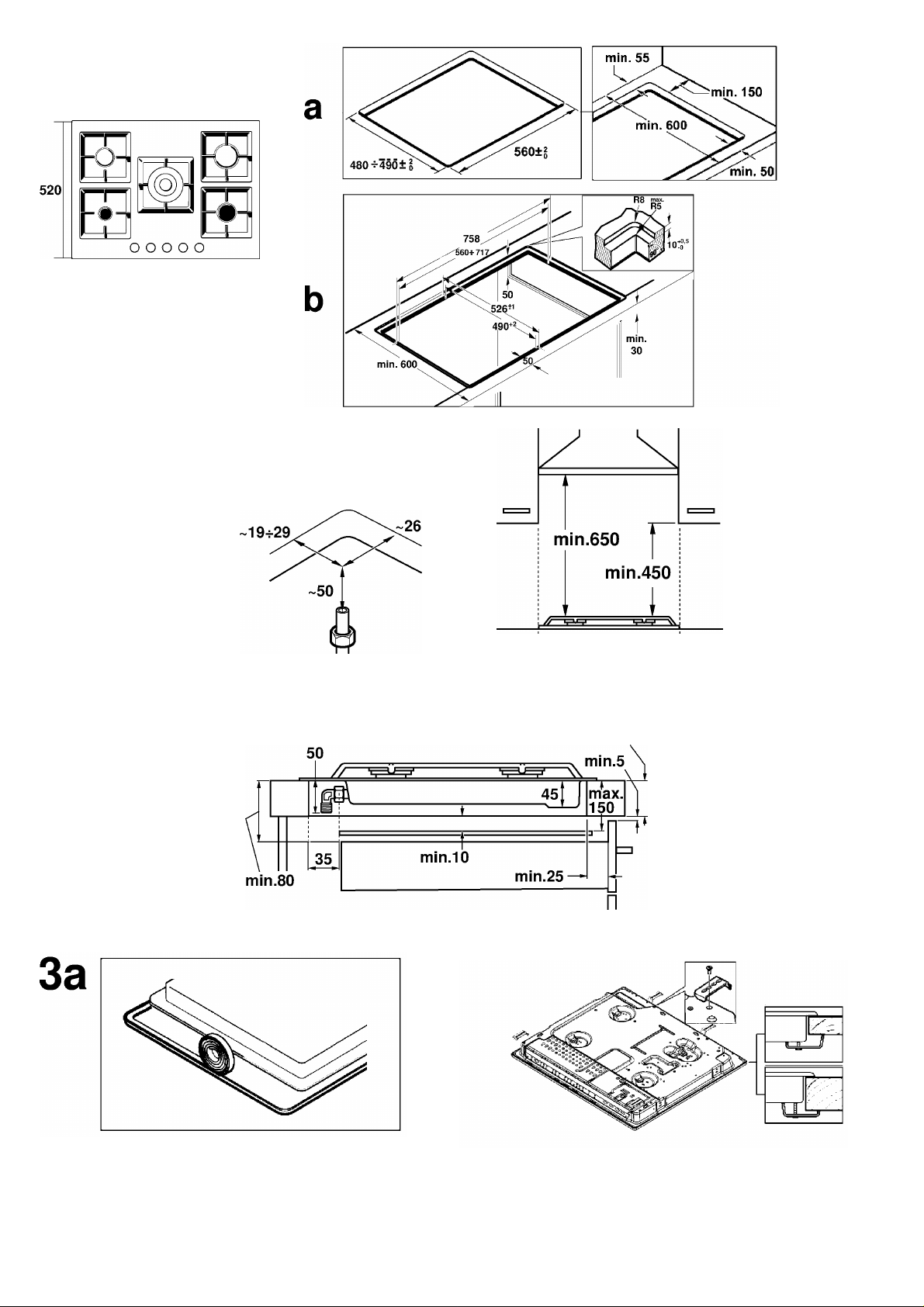
Wenn eine Dunstabzugshaube angebracht wird, muss dies gemäß
der Montageanleitung und immer unter Berücksichtigung eines
vertikalen Mindestabstandes von 650 mm zum Kochfeld gesche
hen.
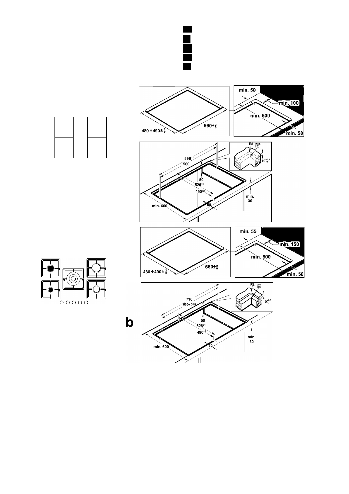
Vorbereitung des Küchenmöbels (Abb. 1-2)
Gemäß der gewünschten Verfahrensweise ein Stück entsprechen
der Größe aus der Arbeitsplatte herausschneiden: normal (a) oder
bündig (b). Fürden bündigen Einbau:
■ Alle Ausschnittarbeiten an der Arbeitsplatte müssen in einem
Fachgeschäft durchgeführt werden.
■ Die Schnittstellen müssen sauber und genau sein, weil man die
Schnittkante an der Oberfläche sieht. Die Stabilität der Möbel
muss auch nach den Schnittarbeiten gewährleistet sein.
Nur Spezialarbeitsplatten verwenden, die temperatur- und was
serfest sind (z. B. aus Naturstein oder gekachelte).
■ Die Einbaumöbel müssen eine Temperaturbeständigkeit bis zu
90 °C aufweisen.
Wenn es sich bei dem Kochfeld um ein elektrisches oder gemisch
tes Kochfeld (Gas und elektrisch) handelt und sich kein Ofen dar
unter befindet, bringen Sie einen Zwischenboden aus nicht
brennbarem Material (z.B. Metall oder Sperrholz) 10 mm unter
dem Boden des Kochfeldes an. So wird ein Zugang zum unteren
Teil des Kochfeldes verhindert.Wenn es sich bei dem Kochfeld um
ein Gaskochfeld handelt, wird empfohlen, den Zwischenboden im
selben Abstand zum Kochfeld anzubringen.
Bei Arbeitsflächen aus Holz firnissen Sie die Schnittflächen mit
Spezialleim, um sie vor Feuchtigkeit zu schützen.
Einbau des Geräts
A) Normaler Einbau (Abb. 3a)
Je nach Modell kann die Klebedichtung bereits im Werk ange
bracht worden sein. Die Klebedichtung dann keinesfalls entfernen,
sieverhindert Durchsickern. Wenn die Dichtung nicht werkseitig
angebracht wurde, kleben Sie sie an den unteren Rand des Koch
felds.
Zur Befestigung des Geräts am Einbaumöbel:
1. Entnehmen Sie die Klammern dem Zubehörbeutel und schrau
ben Sie sie in der angegebenen Postition an, so dass sie sich frei
drehen.
2. Fügen Sie das Kochfeld mittig ein.
Drücken Sie die Ränder so lange nach unten, bis der gesamte
Rand aufliegt.
3. Drehen Sie die Klammern und ziehen Sie diese fest an.
Die Position der Klammern hängtvon der Dicke der
Arbeitsoberfläche ab.
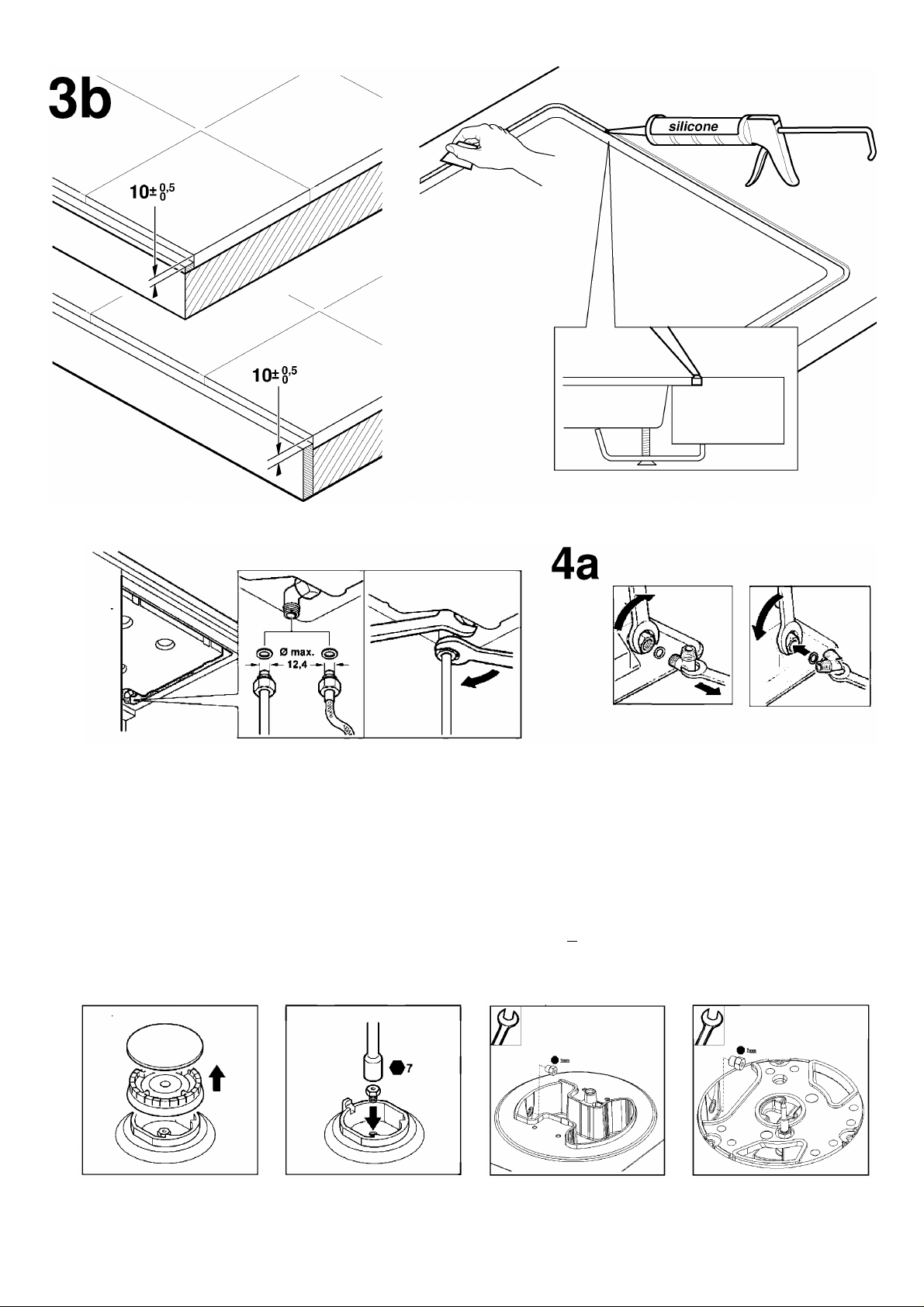
B) Bündiger Einbau (Abb. 3b)
1. Führen Sie den normalen Einbau des Gerätes durch und stellen
Sie sicher, dass ein gleichmäßiger Spalt am äußeren Rand vor
handen ist. Das Kochfeld muss leicht unter der Arbeitsoberfläche
bleiben.
Bei gekachelten Arbeitsflächen ggf. die Auflageflächen mit Hilfe
von temperatur- und wasserfesten Leisten erhöhen.
2. Den Betrieb und die Stellung des Gerätes prüfen.
3. Füllen Sie die Nut zwischen der Arbeitsplatte und dem Kochfeld
mit herkömmlichem Silikonleim in dergewünschten Farbe aus.
Hinweis: Wird bei Oberflächen aus Naturstein ungeeignetes Si
likon verwendet, können Verfärbungen entstehen, die dann nicht
mehr entfernt werden können. Geeignetes Silikonmaterial ist bei
unserem Kundendienst (Teilenummer310818) erhältlich. Beach
ten Sie die Benutzungshinweise des Herstellers.
4. Streichen Sie den Silikonleim mit einer mit Seife angefeuchteten
Spachtel bzw. mit einem mit Seife angefeuchteten Finger glatt,
bevor sich eine Schicht bildet.

5. Den Silikonleim trocknen lassen, bevor das Gerät in Betrieb ge
nommen wird.
Ausbau des Kochfeldes
Trennen Sie das Gerät von der Strom- und Gasversorgung.
Schrauben Sie die Klammern auf und folgen Sie den Einbauschrit
ten in umgekehrter Reihenfolge.
Gasanschluss (Abb. 4)
Am Ende des Eingangsrohrs zum Gaskochfeld befindet sich ein 1/
2” (20,955 mm) Gewinde. Dieses Gewinde ermöglicht:
■ einen Festanschluss.
■ einen Anschluss mit einem Metallschlauch (L min. 1 m max. 3 m).
Die mitgelieferte Dichtung (034308) muss zwischen dem Auslass
der Sammelleitung und dem Gasanschluss angebracht werden.
Der Schlauch sollte nicht in Kontakt zu den beweglichen Teilen der
Einbaueinheit gelangen (z. B. einer Schublade) oder durch
Öffnungen verlegt werden, die verschlossen werden könnten.
Beim Anschluss, egal welcher Art, darf der Krümmer nicht
bewegt oder verdreht und so aus seiner werkseitigen Position
gebracht werden.
Wenn ein zylindrischer Anschluss hergestellt werden soll, ersetzen
Sie den werkseitig installierten Krümmer mit dem Krümmer aus
dem Zubehörbeutel. Abb. 4a.
Vergessen Sie nicht, dazwischen die Dichtung anzubringen.
: Gasaustrittsgefahr!
Nach Arbeiten an einer Anschlussstelle diese immer auf Dichtheit
prüfen.
Der Hersteller übernimmt für den Gasaustritt an einer Anschluss
stelle, an derzuvor hantiert wurde, keine Verantwortung.
Elektrischer Anschluss (Abb. 5)
Prüfen Sie, ob Spannung und Nennleistung des Geräts mitder
elektrischen Installation übereinstimmen.
Die Kochfelder werden mit Netzkabel mit oder ohne Stecker gelie
fert.
Mit Stecker ausgestattete Geräte dürfen nur in vorschriftsmäßig
angebrachte, geerdete Steckdosen gesteckt werden.
Es muss ein allpoligerTrennschalter mit mindestens 3 mm Kon
taktabstand angebracht werden (außer bei Anschluss an eine frei
zugängliche Steckdose).
Das Gerät gehört zum Typ "Y". Das Zuleitungskabel darf nicht vom
Benutzer, sondern nurvom Kundendienst ausgetauschtwerden.
Sowohl Kabeltyp als auch minimaler Querschnitt müssen
berücksichtigt werden.
Umstellung auf eine andere Gasart
Wenn die einschlägigen Bestimmungen des jeweiligen Landes
dies erlauben, kann dieses Gerät auf andere Gasarten umgestellt
werden (siehe Typenschild). Die hierfür notwendigen Teile befin
den sich im mitgelieferten Umbaukit (je nach Modell) oder können
über den Kundendienst bezogen werden. Es müssen folgende
Schritte befolgt werden:
A) Austausch der Düsen (Abb. 6):
1. Nehmen Sie die Roste, Brennerdeckel und Verteiler ab.
2. Tauschen Sie die Düsen mit dem über unseren Kundendienst
erhältlichen Schlüssel mit der Artikelnummer 340847 aus (für
Doppelbrenner und Dreiflammenbrenner Artikelnummer
340808), siehe Tabelle II. Achten Sie dabei besonders darauf,
dass die Düse beim Herausdrehen oder Befestigen am Brenner
nicht abbricht.
Stellen Sie sicher, sie bis zum Anschlag eingedreht zu haben, um
eine gute Abdichtung zu erreichen.
Bei diesen Brennern muss keine Einstellung der Primärluftvorgenommen werden
3. Bringen Sie die Verteiler und Brennerdeckel auf den entspre
chenden Kochstellen an. Außerdem müssen die Roste korrekt in
den entsprechenden Halteelementen eingesetzt werden.
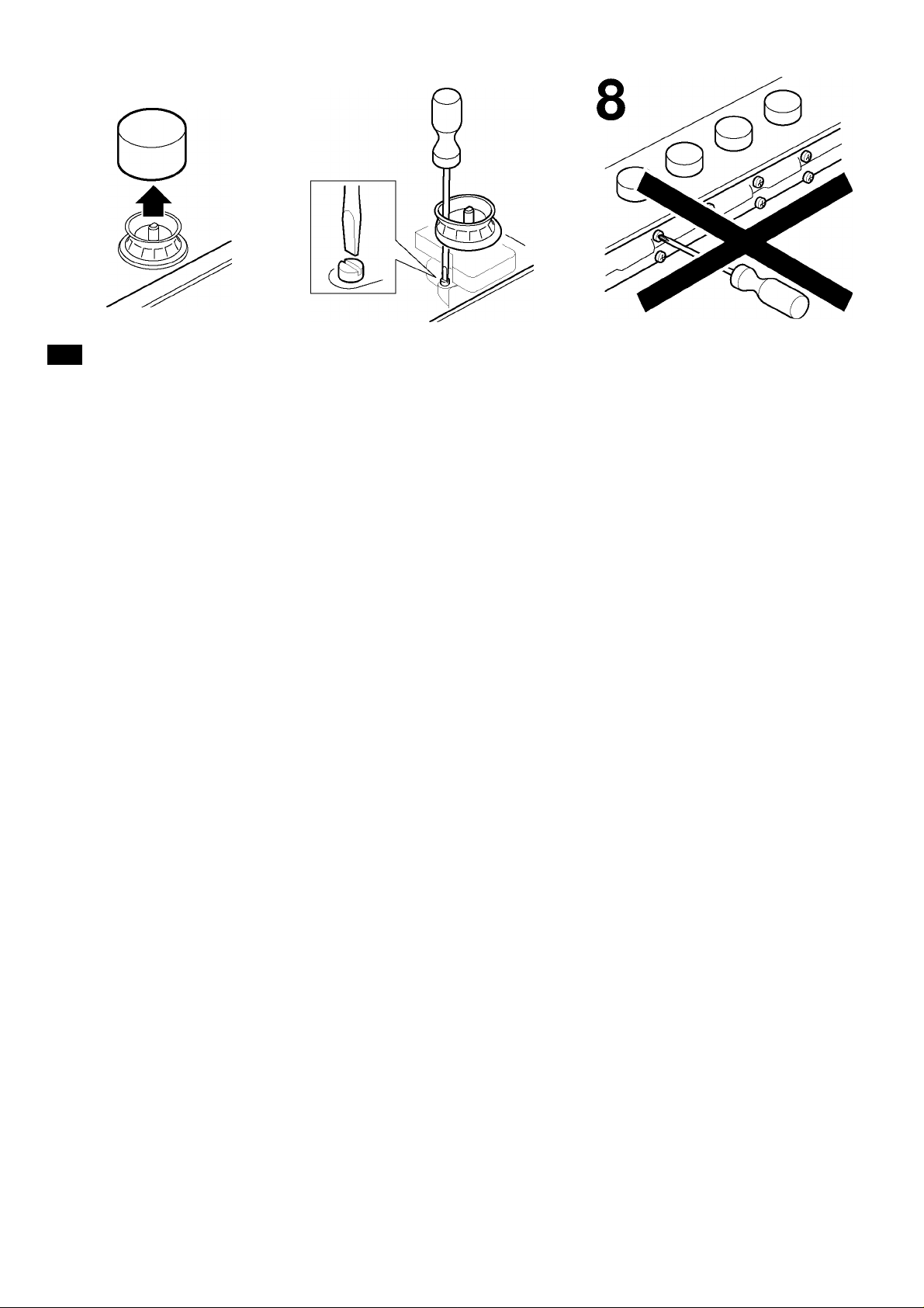
B) Einstellung der Gashähne
1. Drehen Sie die Bedienknebel auf die niedrigste Stufe.
2. Ziehen Sie die Bedienknebel der Gashähne ab. Abb. 7.
Es wird eine Knebeldichtung aus flexiblem Gummi sichtbar. Es ist
ausreichend, diese mitder Schraubenzieherspitze beiseite zu
drücken, um an die Einstellschraube des Gashahns zu gelangen.
Bauen Sie die Knebeldichtungen niemals aus.
3. Stellen Sie die minimale Gaszufuhr ein, indem Sie die Bypass
Schraube mit einem Schlitzschraubenzieher drehen.
Je nach Gasart, auf die Sie umstellen (siehe Tabelle III), müssen
entsprechende Schritte durchgeführtwerden:
A: die Bypass-Schrauben ganz anziehen.
B: die Bypass-Schrauben bis zum korrekten Gasaustritt an den
Brennern lockern: stellen Sie sicher, dass der Brenner bei einer
Umstellung des Bedienknebels von der höchsten auf die nied
rigste Stufe nicht ausgeht und nicht zurückschlägt.
C: die Bypass-Schrauben müssen von einem autorisierten Fach
mann ausgetauschtwerden.
D: nehmen Sie keine Veränderungen an den Bypass-Schrauben
vor.
Wenn Sie nicht an die Bypass-Schraube gelangen sollten, bauen
Sie die Fettauffangschale, die mit dem restlichen Kochfeld ver
schraubt ist, aus. Zum Abnehmen gehen Sie wie folgt vor:
1. Nehmen Sie alle Roste, Brennerdeckel, Verteiler und Bedienkne
bel ab.
2. Lockern Sie die Brenner-Schrauben.
3. Für den Wiedereinbau des Geräts folgen Sie den Ausbauanwei
sungen in umgekehrter Reihenfolge.
Um die Dichtheit zu gewährleisten, müssen alle Knebeldichtun
gen eingesetzt werden. Die Dichtungen sind für den fehlerfreien
Betrieb des Geräts unerlässlich, da sie das Eindringen von
Flüssigkeiten und Schmutz ins Geräteinnere verhindern.
Bauen Sie niemals die Achse des Gashahns aus (Abb. 8). Bei
einer Störung den kompletten Gashahn ersetzen.
Achtung!
Bringen Sie den Aufkleber mit der umgestellten Gasart in der
Nähe des Typenschildes an.
en
Safety precautions
Read the appliance instructions before installing and using.
The graphics in these Assembly instructions are given as a guide
only.
The manufacturer is exempt from all liability if this manual's
requirements are not complied with.
All operations relating to installation, regulation and
conversion to other gas types must be carried out by an
authorised installation engineer, respecting all applicable
regulations, standards and the specifications of the local gas
and electricity providers.
You are recommended to contact the Technical Assistance
Service to convert to another gas type.
Before you begin, turn off the appliance's electricity and gas
supply.
This appliance has been designed for home use only, not for
commercial or professional use. This appliance cannot be installed
on yachts or in caravans. The warranty will only be valid if the
appliance is used for the purpose for which it was designed.
Before installing, check that local distribution conditions (gas type
and pressure) and the appliance's adjustment are compatible (see
table I). The appliance's adjustment conditions are written on the
label or the specifications plate.
This appliance can only be installed in a well-ventilated place in
accordance with existing regulations and ventilation specifications.
The appliance must not be connected to a combustion product
removal device.
The supply cable must be attached to the unit to prevent it from
touching hot parts of the oven or hob.
Appliances with electrical supply must be earthed.
Do not tamper with the appliance's interior. If necessary, call our
Technical Assistance Service.
Before installing
This appliance is class 3 type, according to the EN 30-1-1
regulation for gas appliances: built-in appliance.
The units next to the appliance must be made of non-flammable
materials. The laminated covering and glue for adhering it must be
heat resistant.
This appliance cannot be installed above fridges, washing
machines, dishwashers or similar.
An oven must have forced ventilation to install a hob above it.
Check the dimensions of the oven in the installation manual.
If an extractor fan is installed, you must follow the installation
manual's instructions, always keeping a minimum distance of
650 mm to the hob.

Preparation of the kitchen unit (fig. 1-2)
Make an appropriate size cut in the worktop surface, depending on
the installation method, standard (a) or flush (b). For flush
installation:
■ All cuts in the worktop surface should be done by a specialised
shop.
■ The cuts should be clean and precise, as the cut edge is on the
surface. The stability of the furniture should also be ensured
after cutting work.
■ Use only specially designed work surfaces, resistant to hightemperature and water (e.g. natural stone or tiled).
■ Surrounding furniture must be resistant to temperatures up to
90 °C.
If the hob is electric or mixed (gas and electricity) and there is no
oven below, place a non-flammable separator (e.g. metal or
plywood) 10 mm from the bottom of the hob. This will prevent
access to the base of the hob.lf the hob is gas, it is
recommendable to place the separator at the same distance.
On wood work surfaces, varnish the cutting surfaces with a special
glue. This protects them from moisture which could collect under
the work surface.
Installation of appliance
A) Standard installation (fig. 3a)
Depending on the model, the adhesive seal may be factory-fitted.
If this is the case, it should not be removed under any
circumstances, since the adhesive seal prevents leaks. If the seal
has not been factory-fitted, apply it to the underside of the hob.
Fitting the appliance onto the kitchen unit:
1. Remove the clips from the accessory bag and screw them into
the position indicated so that they can turn freely.
2. Insert and centre the hob.
Press the sides of the hob until it is supported around its entire
perimeter.
3. Turn the clips and tighten them fully.
The position of the clips depends on how thick the work surface is.
B) Flush installation (fig. 3b)
1. Complete a normal installation of the appliance making sure that
it is surrounded by a uniform slot. The hob surface should be
slightly below the work surface.
For tile worktops, if necessary, raise the bearing surfaces with
strips resistant to water and temperatures.
2. Check the operation and position of appliance.
3. Fill the gap between the worktop and hob with conventional
silicone adhesive appropriate in the colour you desire.
Note: If unsuitable silicone adhesive is used on natural stone
surfaces then this can produce colours that can not be removed.
Our Technical Assistance Service can provide you with the most
suitable glue (code 310818). Please note the manufacturers
instructions for use.
4. Smooth the silicone adhesive with a scraper or wet finger
moistened with soap and water before it forms a layer.
5. Allow the silicone adhesive to dry before using the appliance.
Removal of hob
Turn off the appliance's electricity and gas supply.
Unscrew the clips and proceed in the reverse order to installation.
Gas connection (fig. 4)
The end of the inlet connection point of the gas hob has a 1/2”
(20.955 mm) thread that allows for:
■ fixed connection.
■ connection using a flexible metal pipe (L min. 1 m - max. 3 m).
The watertight seal (034308) supplied must be inserted between
the manifold outlet and the gas supply.
You must prevent the pipe from coming into contact with moving
parts of the kitchen unit (for example, a drawer) and prevent
access to any spaces which might become obstructed.
Do not move the L-tube from the factory-fitted position,
regardless of the connection type.
If you need to make a cylindrical connection, replace the factoryfitted L-tube with the one in the accessory bag. Fig. 4a.
Please remember to insert the seal.
: Danger of leaks!
If any connection is handled, check the seal.
The manufacturer is not liable for any connection leaking, after
being handled.
Electric connection (fig. 5)
Check that the voltage and power of the appliance are compatible
with the electrical installation.
The hobs are supplied with a power cable with or without a wall
socket plug.
Appliances with plugs must only be connected to sockets that
have earth wires correctly installed.
Provide an omnipolar cut-off switch with a minimum contact
opening of 3 mm (except for plug connections, if the user has
access to it).
This appliance is type “Y”: the supply cable can only be changed
by the Technical Assistance Service and not the user. The cable
type and minimum cross-section must be respected.
Changing the gas type
If the country's regulations allow, this appliance can be adapted to
other types of gas (see specifications plate). The components
required for this are in the transformation kit supplied (depending
on the model) or are available from ourTechnical Assistance
Service. The following steps should be taken:
A) Changing the nozzles (fig. 6):
1. Remove the pan supports, burner caps and diffusers.
2. Change the nozzles using the spanner code 340847 (code
340808 for double-flame burners or triple-flame burners)
provided by ourTechnical Assistance Service, see table II,
taking special care to ensure that the nozzle does not fall when it
is removed from or fitted to the burner.
Ensure that it is completely tightened in order to guarantee the
seal.
Primary air adjustment is not necessary with these burners.
3. Position the diffusers and burner caps on the corresponding
rings. The pan supports must also be correctly positioned in their
fasteners.
B) Adjusting the taps
1. Set the control knobs to minimum.
2. Remove the control knobs from the taps. Fig. 7.
It has a flexible rubber valve reinforcing ring. Simply press on this
seal with the tip of a screwdriver to allow access to the tap
adjusting screw. Never remove the valve reinforcing ring.
3. Adjust the minimum ring setting by turning the by-pass screw
using a flat head screwdriver.
Depending on the gas to which your appliance is going to be
adapted, see table III, carry out the corresponding action:
A: firmly tighten the by-pass screws.
B: loosen the by-pass screws until the gas flow from the burners
is correct: when adjusting the control knob between maximum
and minimum, the burner does not go out, nor is there a flame
backdraught created.
C: the by-pass screws need to be changed by an authorised
engineer.
D: do not touch the by-pass screws.
If the by-pass screw cannot be accessed, disassemble the grease
drip tray, which is fitted to the hob with a series of screws. The
following steps must be taken to remove it:
1. Remove all pan supports, burner caps, diffusers and control
knobs.
2. Remove the screws from the burners.
3. To reinstall the appliance, proceed in the reverse orderto
disassembly.
All valve reinforcing rings must be in position to ensure
watertightness. These devices are essential for the correct
operation of the appliance as they prevent liquids and dirt from
entering the appliance.
Never remove the tap spindle (Fig. 8). In the event of a
malfunction, change the whole tap.
Caution!
After finishing, the sticker indicating the new type of gas must be
placed close to the specifications plate.
es
Indicaciones de seguridad
Lea las instrucciones del aparato antes de proceder a su
instalación y uso.
Los gráficos representados en estas instrucciones de montaje son
orientativos.
El fabricante queda exento de toda responsabilidad si no se
cumplen las disposiciones de este manual.
 Loading...