

Bosch PFS 1000, PFS 2000 User guide [ml]
Robert Bosch GmbH
Power Tools Division
70764 Leinfelden-Echterdingen
GERMANY
www.bosch-pt.com
2 609 007 770 (2014.09) PS / 251 EURO
PFS
1000 | 2000
de Originalbetriebsanleitung
en Original instructions
fr Notice originale
es Manual original
pt Manual original
it Istruzioni originali
nl Oorspronkelijke gebruiks-
aanwijzing
da Original brugsanvisning
sv Bruksanvisning i original
no Original driftsinstruks
fi Alkuperäiset ohjeet

2 |
Deutsch . . . . . . . . . . . . . . . . . . . . . . . . . . . . . . . . . . . . . . . . . Seite 7
English . . . . . . . . . . . . . . . . . . . . . . . . . . . . . . . . . . . . . . . . . . Page 15
Français . . . . . . . . . . . . . . . . . . . . . . . . . . . . . . . . . . . . . . . . . Page 23
Español . . . . . . . . . . . . . . . . . . . . . . . . . . . . . . . . . . . . . . . . Página 31
Português. . . . . . . . . . . . . . . . . . . . . . . . . . . . . . . . . . . . . . . Página 40
Italiano . . . . . . . . . . . . . . . . . . . . . . . . . . . . . . . . . . . . . . . . . Pagina 48
Nederlands . . . . . . . . . . . . . . . . . . . . . . . . . . . . . . . . . . . . . Pagina 57
Dansk . . . . . . . . . . . . . . . . . . . . . . . . . . . . . . . . . . . . . . . . . . . Side 64
Svenska . . . . . . . . . . . . . . . . . . . . . . . . . . . . . . . . . . . . . . . . . Sida 72
Norsk . . . . . . . . . . . . . . . . . . . . . . . . . . . . . . . . . . . . . . . . . . . Side 79
Suomi. . . . . . . . . . . . . . . . . . . . . . . . . . . . . . . . . . . . . . . . . . . . Sivu 86
2 609 007 770 | (16.9.14) Bosch Power Tools
| 3
2
3
1
4
5
6
19
20 21
7
18
18
22
23
24
17
PFS 1000
PFS 2000
Bosch Power Tools 2 609 007 770 | (16.9.14)
4 |
A1
B
18
25
22
24
A2
C
4
18
11
10
9
(PFS 2000)
2
3
8
D1 D2
12
12
12
2 609 007 770 | (16.9.14) Bosch Power Tools
| 5
E
G
–
20
+
F
H
22
5
21
19
I
Bosch Power Tools 2 609 007 770 | (16.9.14)
J
26
23
6 |
K
13
108/9
11
2
3
8/9
16
15
14
12
7
12 14
2 609 007 770 | (16.9.14) Bosch Power Tools

Deutsch | 7
Wenn der Betrieb des Elektrowerkzeuges in feuchter
Deutsch
Sicherheitshinweise
Allgemeine Sicherheitshinweise für Elektrowerkzeuge
WARNUNG
haltung der Sicherheitshinweise und Anweisungen können
elektrischen Schlag, Brand und/oder schwere Verletzungen
verursachen.
Bewahren Sie alle Sicherheitshinweise und Anweisungen
für die Zukunft auf.
Der in den Sicherheitshinweisen verwendete Begriff „Elektrowerkzeug“ bezieht sich auf netzbetriebene Elektrowerkzeuge
(mit Netzkabel) und auf akkubetriebene Elektrowerkzeuge
(ohne Netzkabel).
Arbeitsplatzsicherheit
Halten Sie Ihren Arbeitsbereich sauber und gut be-
leuchtet. Unordnung oder unbeleuchtete Arbeitsbereiche
können zu Unfällen führen.
Arbeiten Sie mit dem Elektrowerkzeug nicht in explosi-
onsgefährdeter Umgebung, in der sich brennbare Flüssigkeiten, Gase oder Stäube befinden. Elektrowerkzeu-
ge erzeugen Funken, die den Staub oder die Dämpfe
entzünden können.
Halten Sie Kinder und andere Personen während der
Benutzung des Elektrowerkzeugs fern. Bei Ablenkung
können Sie die Kontrolle über das Gerät verlieren.
Elektrische Sicherheit
Der Anschlussstecker des Elektrowerkzeuges muss in
die Steckdose passen. Der Stecker darf in keiner Weise
verändert werden. Verwenden Sie keine Adapterstecker gemeinsam mit schutzgeerdeten Elektrowerkzeugen. Unveränderte Stecker und passende Steckdosen ver-
ringern das Risiko eines elektrischen Schlages.
Vermeiden Sie Körperkontakt mit geerdeten Oberflä-
chen wie von Rohren, Heizungen, Herden und Kühlschränken. Es besteht ein erhöhtes Risiko durch elektri-
schen Schlag, wenn Ihr Körper geerdet ist.
Halten Sie Elektrowerkzeuge von Regen oder Nässe
fern. Das Eindringen von Wasser in ein Elektrowerkzeug
erhöht das Risiko eines elektrischen Schlages.
Zweckentfremden Sie das Kabel nicht, um das Elektro-
werkzeug zu tragen, aufzuhängen oder um den Stecker
aus der Steckdose zu ziehen. Halten Sie das Kabel fern
von Hitze, Öl, scharfen Kanten oder sich bewegenden
Geräteteilen. Beschädigte oder verwickelte Kabel erhö-
hen das Risiko eines elektrischen Schlages.
Wenn Sie mit einem Elektrowerkzeug im Freien arbei-
ten, verwenden Sie nur Verlängerungskabel, die auch
für den Außenbereich geeignet sind. Die Anwendung ei-
nes für den Außenbereich geeigneten Verlängerungskabels verringert das Risiko eines elektrischen Schlages.
Bosch Power Tools 2 609 007 770 | (16.9.14)
Lesen Sie alle Sicherheitshinweise und
Anweisungen. Versäumnisse bei der Ein-
Umgebung nicht vermeidbar ist, verwenden Sie einen
Fehlerstromschutzschalter. Der Einsatz eines Fehler-
stromschutzschalters vermindert das Risiko eines elektrischen Schlages.
Sicherheit von Personen
Seien Sie aufmerksam, achten Sie darauf, was Sie tun,
und gehen Sie mit Vernunft an die Arbeit mit einem
Elektrowerkzeug. Benutzen Sie kein Elektrowerkzeug,
wenn Sie müde sind oder unter dem Einfluss von Drogen, Alkohol oder Medikamenten stehen. Ein Moment
der Unachtsamkeit beim Gebrauch des Elektrowerkzeuges
kann zu ernsthaften Verletzungen führen.
Tragen Sie persönliche Schutzausrüstung und immer
eine Schutzbrille. Das Tragen persönlicher Schutzausrüs-
tung, wie Staubmaske, rutschfeste Sicherheitsschuhe,
Schutzhelm oder Gehörschutz, je nach Art und Einsatz des
Elektrowerkzeuges, verringert das Risiko von Verletzungen.
Vermeiden Sie eine unbeabsichtigte Inbetriebnahme.
Vergewissern Sie sich, dass das Elektrowerkzeug ausgeschaltet ist, bevor Sie es an die Stromversorgung
und/oder den Akku anschließen, es aufnehmen oder
tragen. Wenn Sie beim Tragen des Elektrowerkzeuges den
Finger am Schalter haben oder das Gerät eingeschaltet an
die Stromversorgung anschließen, kann dies zu Unfällen
führen.
Entfernen Sie Einstellwerkzeuge oder Schrauben-
schlüssel, bevor Sie das Elektrowerkzeug einschalten.
Ein Werkzeug oder Schlüssel, der sich in einem drehenden
Geräteteil befindet, kann zu Verletzungen führen.
Vermeiden Sie eine abnormale Körperhaltung. Sorgen
Sie für einen sicheren Stand und halten Sie jederzeit
das Gleichgewicht. Dadurch können Sie das Elektrowerk-
zeug in unerwarteten Situationen besser kontrollieren.
Tragen Sie geeignete Kleidung. Tragen Sie keine weite
Kleidung oder Schmuck. Halten Sie Haare, Kleidung
und Handschuhe fern von sich bewegenden Teilen. Lo-
ckere Kleidung, Schmuck oder lange Haare können von
sich bewegenden Teilen erfasst werden.
Wenn Staubabsaug- und -auffangeinrichtungen mon-
tiert werden können, vergewissern Sie sich, dass diese
angeschlossen sind und richtig verwendet werden. Ver-
wendung einer Staubabsaugung kann Gefährdungen
durch Staub verringern.
Verwendung und Behandlung des Elektrowerkzeuges
Überlasten Sie das Gerät nicht. Verwenden Sie für Ihre
Arbeit das dafür bestimmte Elektrowerkzeug. Mit dem
passenden Elektrowerkzeug arbeiten Sie besser und sicherer im angegebenen Leistungsbereich.
Benutzen Sie kein Elektrowerkzeug, dessen Schalter
defekt ist. Ein Elektrowerkzeug, das sich nicht mehr ein-
oder ausschalten lässt, ist gefährlich und muss repariert
werden.
Ziehen Sie den Stecker aus der Steckdose und/oder
entfernen Sie den Akku, bevor Sie Geräteeinstellungen
vornehmen, Zubehörteile wechseln oder das Gerät

8 | Deutsch
weglegen. Diese Vorsichtsmaßnahme verhindert den un-
beabsichtigten Start des Elektrowerkzeuges.
Bewahren Sie unbenutzte Elektrowerkzeuge außer-
halb der Reichweite von Kindern auf. Lassen Sie Personen das Gerät nicht benutzen, die mit diesem nicht vertraut sind oder diese Anweisungen nicht gelesen
haben. Elektrowerkzeuge sind gefährlich, wenn sie von
unerfahrenen Personen benutzt werden.
Pflegen Sie Elektrowerkzeuge mit Sorgfalt. Kontrollie-
ren Sie, ob bewegliche Teile einwandfrei funktionieren
und nicht klemmen, ob Teile gebrochen oder so beschädigt sind, dass die Funktion des Elektrowerkzeuges beeinträchtigt ist. Lassen Sie beschädigte Teile vor
dem Einsatz des Gerätes reparieren. Viele Unfälle haben
ihre Ursache in schlecht gewarteten Elektrowerkzeugen.
Halten Sie Schneidwerkzeuge scharf und sauber. Sorg-
fältig gepflegte Schneidwerkzeuge mit scharfen Schneidkanten verklemmen sich weniger und sind leichter zu führen.
Verwenden Sie Elektrowerkzeug, Zubehör, Einsatz-
werkzeuge usw. entsprechend diesen Anweisungen.
Berücksichtigen Sie dabei die Arbeitsbedingungen und
die auszuführende Tätigkeit. Der Gebrauch von Elektro-
werkzeugen für andere als die vorgesehenen Anwendungen kann zu gefährlichen Situationen führen.
Service
Lassen Sie Ihr Elektrowerkzeug nur von qualifiziertem
Fachpersonal und nur mit Original-Ersatzteilen reparieren. Damit wird sichergestellt, dass die Sicherheit des
Elektrowerkzeuges erhalten bleibt.
Sicherheitshinweise für Feinsprühsysteme
Halten Sie Ihren Arbeitsbereich sauber, gut beleuchtet
und frei von Farb- oder Lösemittelbehältern, Lappen
und sonstigen brennbaren Materialien. Mögliche Ge-
fahr der Selbstentzündung. Halten Sie funktionsfähige
Feuerlöscher/Löschgeräte zu jeder Zeit verfügbar.
Sorgen Sie für gute Belüftung im Sprühbereich und für
ausreichend Frischluft im gesamten Raum. Verdunsten-
de brennbare Lösemittel schaffen eine explosive Umgebung.
Sprühen und reinigen Sie nicht mit Materialien, deren
Flammpunkt unterhalb von 55 °C liegt. Verwenden Sie
Materialien auf der Basis von Wasser, schwerflüchtigen Kohlenwasserstoffen oder ähnlichen Materialien.
Leichtflüchtige verdunstende Lösemittel schaffen eine explosive Umgebung.
Sprühen Sie nicht im Bereich von Zündquellen wie sta-
tischen Elektrizitätsfunken, offenen Flammen, Zündflammen, heißen Gegenständen, Motoren, Zigaretten
und Funken vom Ein- und Ausstecken von Stromkabeln
oder der Bedienung von Schaltern. Derartige Funken-
quellen können zu einer Entzündung der Umgebung führen.
Versprühen Sie keine Materialien, bei denen nicht be-
kannt ist, ob sie eine Gefahr darstellen. Unbekannte Ma-
terialien können gefährdende Bedingungen schaffen.
Tragen Sie zusätzliche persönliche Schutzausrüstung
wie entsprechende Schutzhandschuhe und Schutzoder Atemschutzmaske beim Sprühen oder der Handhabung von Chemikalien. Das Tragen von Schutzausrüs-
tung für entsprechende Bedingungen verringert die Aussetzung gegenüber gefährdenden Substanzen.
Geben Sie acht auf etwaige Gefahren des Sprühguts.
Beachten Sie die Markierungen auf dem Behälter oder
die Herstellerinformationen des Sprühguts, einschließlich der Aufforderung zur Verwendung persönlicher Schutzausrüstung. Den Herstelleranweisungen ist
Folge zu leisten, um das Risiko von Feuer sowie durch Gifte, Karzinogene etc. hervorgerufenen Verletzungen zu verringern.
Halten Sie den Stecker des Netzkabels und den Schal-
terdrücker der Sprühpistole frei von Farbe und anderen Flüssigkeiten. Halten Sie nie das Kabel zur Unterstützung an den Steckverbindungen. Versäumnisse bei
der Einhaltung können elektrischen Schlag zur Folge haben.
Beaufsichtigen Sie Kinder. Damit wird sichergestellt,
dass Kinder nicht mit dem Feinsprühsystem spielen.
Produkt- und Leistungsbeschreibung
Lesen Sie alle Sicherheitshinweise und Anweisungen. Versäumnisse bei der Einhaltung
der Sicherheitshinweise und Anweisungen
können elektrischen Schlag, Brand und/oder
schwere Verletzungen verursachen.
Bestimmungsgemäßer Gebrauch
PFS 1000
Das Elektrowerkzeug ist nur bestimmt zum Zerstäuben von lösemittelhaltigen und wasserverdünnbaren Lackfarben, Lasuren, Grundierungen, Klarlacken, Kraftfahrzeug-Decklacken,
Beizen und Ölen.
Das Elektrowerkzeug kann auch zum Sprühen von höher verdünnten Dispersions- und Latexfarben verwendet werden.
Das Elektrowerkzeug ist nicht geeignet zum Verarbeiten von
Laugen, säurehaltigen Beschichtungsstoffen, körnigem und
körperhaltigem Sprühmaterial sowie spritz- und tropfgehemmten Materialien.
PFS 2000
Das Elektrowerkzeug ist nur bestimmt zum Sprühen von Dispersions- und Latexfarben, lösemittelhaltigen und wasserverdünnbaren Lackfarben, Lasuren, Grundierungen, Klarlacken,
Beizen und Ölen (ALLPaint).
Das Elektrowerkzeug ist nicht geeignet zum Verarbeiten von
Laugen, säurehaltigen Beschichtungsstoffen und Fassadenfarben.
2 609 007 770 | (16.9.14) Bosch Power Tools

Deutsch | 9
Abgebildete Komponenten
Die Nummerierung der abgebildeten Komponenten bezieht
sich auf die Darstellung des Elektrowerkzeuges auf den Grafikseiten.
1Sprühpistole
2 Luftkappe
3 Überwurfmutter
4 Schlauchanschluss (Sprühpistole)
5 Stellrad für Sprühmaterialmenge
6 Bedienschalter
7 Behälter für Sprühmaterial
8 Düsenkappe (grau: für Anwendung „Holz“)
9 Düsenkappe (weiß: für Anwendung „Wand“)
(PFS 2000)
10 O-Ring
11 Dichtscheibe
12 Steigrohr
13 Düsennadel
14 Behälterdichtung
15 Entlüftungsbohrung
16 Farbkanal
17 Luftschlauch
18 Bajonettverschluss
19 Basiseinheit
20 Ein-/Ausschalter
21 Tragegriff
22 Tragegurt
23 Luftfilterabdeckung
24 Schlauchanschluss (Basiseinheit)
25 Öse für Tragegurt
26 Luftfilter
*Abge bildetes oder beschriebenes Zubehör gehört nicht zum
Standard-Lieferumfang. Das vollständige Zubehör finden S ie in
unserem Zubehörprogramm.
Technische Daten
Feinsprühsystem PFS 1000 PFS 2000
Sachnummer
Nennaufnahmeleistung
Förderleistung
Zeitaufwand für 2 m
2
Farbauftrag min 2 1,3
ml/min 100 200
Volumen des Behälters für Sprühmaterial
Düsenkappe 8 (grau)
– Anwendungsfall „Holz“:
Sprühen von lösemittelhaltigen und wasserverdünnbaren Lackfarben,
Lasuren, Grundierungen, Klarlacken, Beizen und Ölen
Düsenkappe 9 (weiß)
– Anwendungsfall „Wand“:
Sprühen von Dispersions- und Latexfarben –
Luftschlauchlänge
Gewicht entsprechend EPTA-Procedure 01/2003
Schutzklasse
Die Angaben gelten für eine Nennspannung [U] von 230 V. Bei abweichenden Spannungen und in länderspezifischen Ausführungen können diese Angaben variieren.
Geräusch-/Vibrationsinformation
Geräuschemissionswerte ermittelt entsprechend
EN 60745-1, EN 50580.
Der A-bewertete Schalldruckpegel des Elektrowerkzeugs beträgt typischerweise 79 dB(A). Unsicherheit K= 3 dB.
Der Geräuschpegel beim Arbeiten kann 80 dB(A) überschreiten.
Gehörschutz tragen!
Schwingungsgesamtwerte a
gen) und Unsicherheit K ermittelt entsprechend EN 60745:
<2,5m/s2, K= 1,5 m/s2.
a
h
Der in diesen Anweisungen angegebene Schwingungspegel
ist entsprechend einem in EN 60745 genormten Messverfahren gemessen worden und kann für den Vergleich von Elek-
(Vektorsumme dreier Richtun-
h
auch für eine vorläufige Einschätzung der Schwingungsbelastung.
Der angegebene Schwingungspegel repräsentiert die hauptsächlichen Anwendungen des Elektrowerkzeugs. Wenn allerdings das Elektrowerkzeug für andere Anwendungen, mit unterschiedlichen Zubehören, mit abweichenden
Einsatzwerkzeugen oder ungenügender Wartung eingesetzt
wird, kann der Schwingungspegel abweichen. Dies kann die
Schwingungsbelastung über den gesamten Arbeitszeitraum
deutlich erhöhen.
Für eine genaue Abschätzung der Schwingungsbelastung sollten auch die Zeiten berücksichtigt werden, in denen das Gerät abgeschaltet ist oder zwar läuft, aber nicht tatsächlich im
Einsatz ist. Dies kann die Schwingungsbelastung über den gesamten Arbeitszeitraum deutlich reduzieren.
trowerkzeugen miteinander verwendet werden. Er eignet sich
3 603 B07 0.. 3 603 B07 3..
W 410 440
ml 800 800
m1,251,25
kg 2,0 2,0
/II /II
Bosch Power Tools 2 609 007 770 | (16.9.14)

10 | Deutsch
Legen Sie zusätzliche Sicherheitsmaßnahmen zum Schutz
des Bedieners vor der Wirkung von Schwingungen fest wie
zum Beispiel: Wartung von Elektrowerkzeug und Einsatzwerkzeugen, Warmhalten der Hände, Organisation der Arbeitsabläufe.
Konformitätserklärung
Wir erklären in alleiniger Verantwortung, dass das unter
„Technische Daten“ beschriebene Produkt allen einschlägigen Bestimmungen der Richtlinien 2011/65/EU,
2014/30/EU, 2006/42/EG einschließlich ihrer Änderungen
entspricht und mit folgenden Normen übereinstimmt:
EN 60745-1, EN 50580.
Technische Unterlagen (2006/42/EG) bei:
Robert Bosch GmbH, PT/ETM9,
70764 Leinfelden-Echterdingen, GERMANY
Henk Becker
Executive Vice President
Engineering
Robert Bosch GmbH, Power Tools Division
70764 Leinfelden-Echterdingen, GERMANY
Leinfelden, 05.06.2014
Helmut Heinzelmann
Head of Product Certification
PT/ETM9
Montage
Ziehen Sie vor allen Arbeiten am Elektrowerkzeug den
Netzstecker aus der Steckdose.
Stellen SIe sicher, dass Sprühpistole und Basiseinheit
vollständig und mit allen Dichtelementen montiert
sind. Nur dadurch ist die Funktion und Sicherheit des Fein-
sprühsystems gewährleistet.
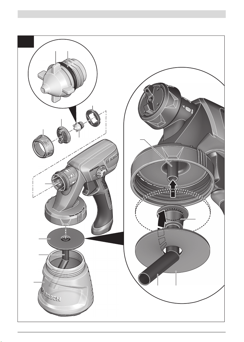
Luftschlauch anschließen (siehe Bilder A1 –A2)
Anschluss der Basiseinheit:
– Stecken Sie einen Bajonettverschluss 18 des Luft-
schlauchs entsprechend den Pfeilmarkierungen fest in die
Aussparungen des Anschlusses 24 der Basiseinheit.
– Drehen Sie den Bajonettverschluss eine Vierteldrehung im
Uhrzeigersinn.
Anschluss an der Sprühpistole:
– Stecken Sie den zweiten Bajonettverschluss 18 des Luft-
schlauchs entsprechend den Pfeilmarkierungen fest in die
Aussparungen des Anschlusses 4 der Sprühpistole.
– Drehen Sie den Bajonettverschluss eine Vierteldrehung im
Uhrzeigersinn.
Hinweis: Entfernen Sie vor dem Einfüllen von Sprühmaterial
den Luftschlauch 17 (Vierteldrehung des Bajonettverschlusses 18 gegen den Uhrzeigersinn; Bajonettverschluss 18 aus
dem Anschluss 4 ziehen).
Tragegurt befestigen (siehe Bild B)
Damit Sie alle zu bearbeitenden Flächen gut erreichen und
flexibel sind, können Sie die Basiseinheit mit dem Tragegurt
22 umhängen.
– Haken Sie in jede Öse 25 jeweils ein Gurtende ein.
Düsenkappe wechseln (PFS 2000) (siehe Bild C)
Hinweis: Prüfen Sie vor der Auswahl der Düsenkappe das
Sprühmaterial durch Umrühren. Dünnflüssiges Mat erial (z. B.
Holzfarbe) oder verdünntes Material lässt sich be sser mit der
grauen Düsenkappe 8 versprühen. Dickflüssigeres Material
(z. B. Holzlack oder Wandfarbe) lässt sich besser mit der weißen Düsenkappe 9 versprühen.
– Zum Wechseln der Düsenkappe schrauben Sie die Über-
wurfmutter 3 ab.
– Ziehen Sie die Luftkappe 2 und die Dichtscheibe 11 ab.
– Schrauben Sie die montierte Düsenkappe ab.
Stellen Sie dabei sicher, dass der O-Ring 10 auf der Düsenkappe bleibt.
– Schrauben Sie die gewünschte Düsenkappe in das Gewin-
de in der Sprühpistole.
– Stecken Sie die Luftkappe 2 mit der Dichtscheibe 11 auf
die Düsenkappe und ziehen Sie sie mit der Überwurfmutter 3 fest.
Betrieb
Ziehen Sie vor allen Arbeiten am Elektrowerkzeug den
Netzstecker aus der Steckdose.
Arbeitsvorbereitung
Sprüharbeiten am Rand von Gewässern oder auf be-
nachbarten Flächen im unmittelbaren Einzugsbereich
sind nicht zulässig.
Achten Sie beim Kauf von Farben, Lacken und Sprühmitteln
auf deren Umweltverträglichkeit.
Sprühfläche vorbereiten
Die Sprühfläche muss sauber, trocken und fettfrei sein.
– Rauen Sie glatte Flächen auf und entfernen Sie danach den
Schleifstaub.
Beim Einsatz können alle nicht abgedeckten Oberflächen
durch den Sprühnebel verunreinigt werden. Bereiten Sie daher die Umgebung der Sprühfläche gründlich vor:
– Fußboden, Einrichtungsgegenstände, Türen, Fenster und
Tür- und Fensterrahmen etc. abdecken oder abkleben.
Sprühmaterial vorbereiten
– Rühren Sie das Sprühmaterial gut durch.
– Verdünnen Sie gegebenenfalls das Sprühmaterial.
2 609 007 770 | (16.9.14) Bosch Power Tools
Sprühmaterial empfohlene
Beizen, Öle, Lasuren, Imprägnierungen,
Rostschutzgrundierungen
Lösemittel- oder wasserverdünnbare
Lackfarben, Grundierungen, Heizkörperlacke, Dickschichtlasuren
Dispersionsfarbe, Latexfarbe mindestens
Achten Sie beim Verdünnen darauf, dass Sprühmateri-
al und Verdünnung zusammenpassen. Bei Verwendung
einer falschen Verdünnung können Klumpen entstehen,
die die Sprühpistole verstopfen.
Achten Sie beim Verdünnen des Sprühmaterials dar-
auf, dass der Flammpunkt des Gemisches nach der Verdünnung wieder über 55 °C liegt. Das Verdünnen von
z. B. lösemittelhaltigen Lacken setzt den Flammpunkt
nach unten.
Sprühmaterial einfüllen (siehe Bilder D1 –D2)
Hinweis: Entfernen Sie vor dem Einfüllen von Sprühmaterial
den Luftschlauch 17 (Vierteldrehung des Bajonettverschlusses 18 gegen den Uhrzeigersinn; Bajonettverschluss 18 aus
dem Anschluss 4 ziehen).
– Schrauben Sie den Behälter 7 von der Sprühpistole ab.
– Füllen Sie das Sprühmaterial maximal bis zur 800-Mar-
kierung in den Behälter 7.
– Drehen Sie das Steigrohr 12 so, dass das Sprühmaterial
fast ohne Rest versprüht werden kann:
für Sprüharbeiten an liegenden Objekten
für Sprüharbeiten über Kopf nach hinten in Richtung
– Führen Sie eine Probesprühung auf einer Testfläche
durch. (siehe „Sprühen“, Seite 11)
Wenn Sie ein optimales Sprühbild erhalten, können Sie das
Sprühen beginnen.
oder
Wenn das Sprühergebnis nicht zufriedenstellend ist oder keine Farbe austritt, gehen Sie vor wie bei „Behebung von Störungen“ auf Seite 13 beschrieben.
nach vorne in Richtung
Düsen-/Luftkappe
Handgriff
Verdünnung
0%
10 %
10 %
Inbetriebnahme (siehe Bild E)
Beachten Sie die Netzspannung! Die Spannung der
Stromquelle muss mit den Angaben auf dem Typenschild
des Elektrowerkzeuges übereinstimmen.
Achten Sie darauf, dass die Basiseinheit während des
Betriebs keinen Staub oder andere Verschmutzungen
ansaugen kann.
Achten Sie darauf, dass Sie die Basiseinheit nie besprü-
hen.
Unterbrechen Sie den Sprühvorgang, wenn während
des Sprühens Flüssigkeit an anderen Stellen als der
vorgesehenen Düse austritt und bringen Sie die Sprühpistole wieder in ordnungsgemäßen Zustand. Es be-
steht die Gefahr eines elektrischen Schlags.
Deutsch | 11
Sprühen Sie nicht auf sich selbst, auf andere Personen
oder Tiere.
Einschalten
Um Energie zu sparen, schalten Sie das Feinsprühsystem nur
ein, wenn Sie es benutzen.
– PFS 2000: Überprüfen Sie, ob die richtige Düsenkappe
montiert ist (siehe „Düsenkappe wechseln“, Seite 10).
– Stecken Sie den Netzstecker in die Steckdose.
– Nehmen Sie die Sprühpistole in die Hand und richten Sie
sie auf die Sprühfläche.
– Schieben Sie den Ein-/Ausschalter 20 nach vorne.
– Drücken Sie den Bedienschalter 6 an der Sprühpistole.
Hinweis: Wenn die Basiseinheit eingeschaltet ist, strömt an
der Luftkappe 2 immer Luft aus.
Ausschalten
– Lassen Sie den Bedienschalter 6 los und schieben Sie den
Ein-/Ausschalter 20 nach hinten.
– Ziehen Sie den Netzstecker aus der Steckdose.
Arbeitshinweise
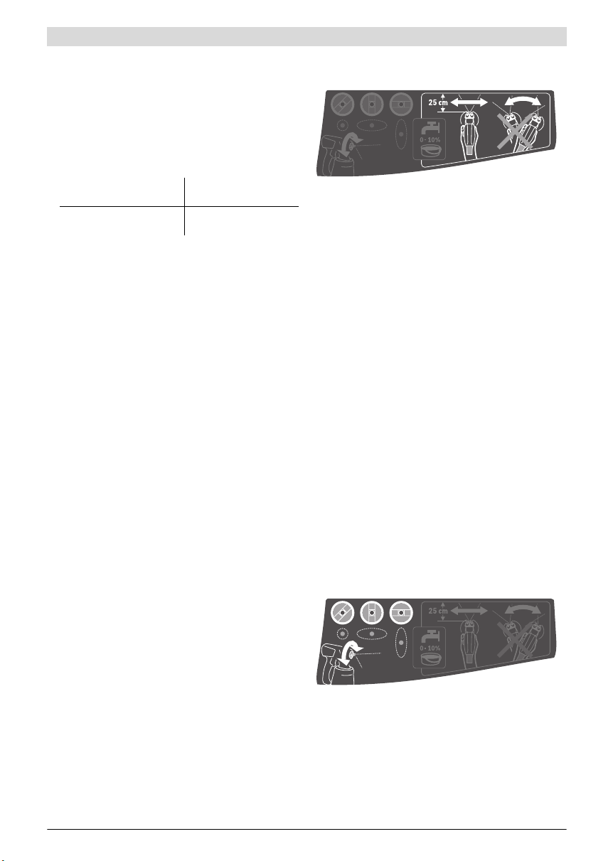
Sprühen (siehe Bild F)
Hinweis: Beachten Sie die Windrichtung, wenn Sie das Elek-
trowerkzeug im Freien benutzen.
– Führen Sie zuerst eine Probesprühung durch und stellen
Sie das Sprühbild und die Sprühmaterialmenge entspre-
chend dem Sprühmaterial ein. (Einstellungen siehe nach-
folgende Abschnitte)
– Halten Sie die Sprühpistole unbedingt in einem gleichmä-
ßigen Abstand von 20– 25 cm senkrecht zum Sprühob-
jekt.
– Beginnen Sie den Sprühvorgang außerhalb der Sprühflä-
che.
– Bewegen Sie die Sprühpistole je nach Sprühbild-Einstel-
lung gleichmäßig quer oder auf und ab.
Eine gleichmäßige Oberflächenqualität entsteht, wenn
sich die Bahnen um 4 – 5 cm überlappen.
– Bei Sprüharbeiten an liegenden Objekten oder bei Sprüh-
arbeiten über Kopf halten Sie die Sprühpistole leicht
schräg und bewegen sich nach hinten von der besprühten
Fläche weg.
Stolpergefahr! Achten Sie auf mögliche Hindernisse im
Raum.
– Vermeiden Sie Unterbrechungen innerhalb der Sprühflä-
che.
Eine gleichmäßige Führung der Sprühpistole ergibt eine ein-
heitliche Oberflächenqualität.
Ein ungleichmäßiger Abstand und Sprühwinkel führt zu star-
ker Farbnebelbildung und damit zu einer ungleichmäßigen
Oberfläche.
Bosch Power Tools 2 609 007 770 | (16.9.14)
12 | Deutsch
– Beenden Sie den Sprühvorgang außerhalb der Sprühflä-
che.
Sprühen Sie den Behälter für das Sprühmaterial nie ganz leer.
Wenn das Steigrohr nicht mehr in das Sprühmaterial taucht,
bricht der Sprühstrahl ab und eine uneinheitliche Oberfläche
entsteht.
Wenn sich das Sprühmaterial an der Düsenkappe und der
Luftkappe ablagert, reinigen Sie beide Teile mit dem verwendeten Verdünnungsmittel.
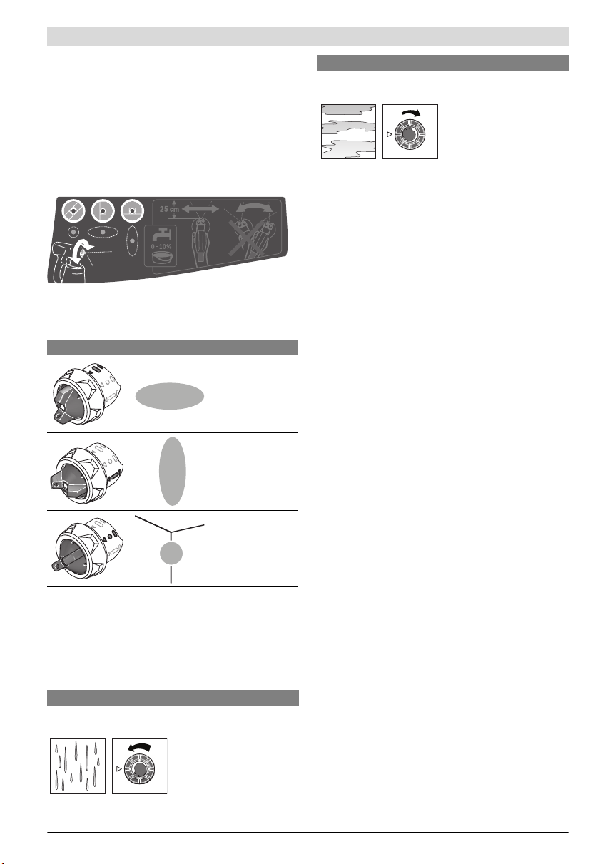
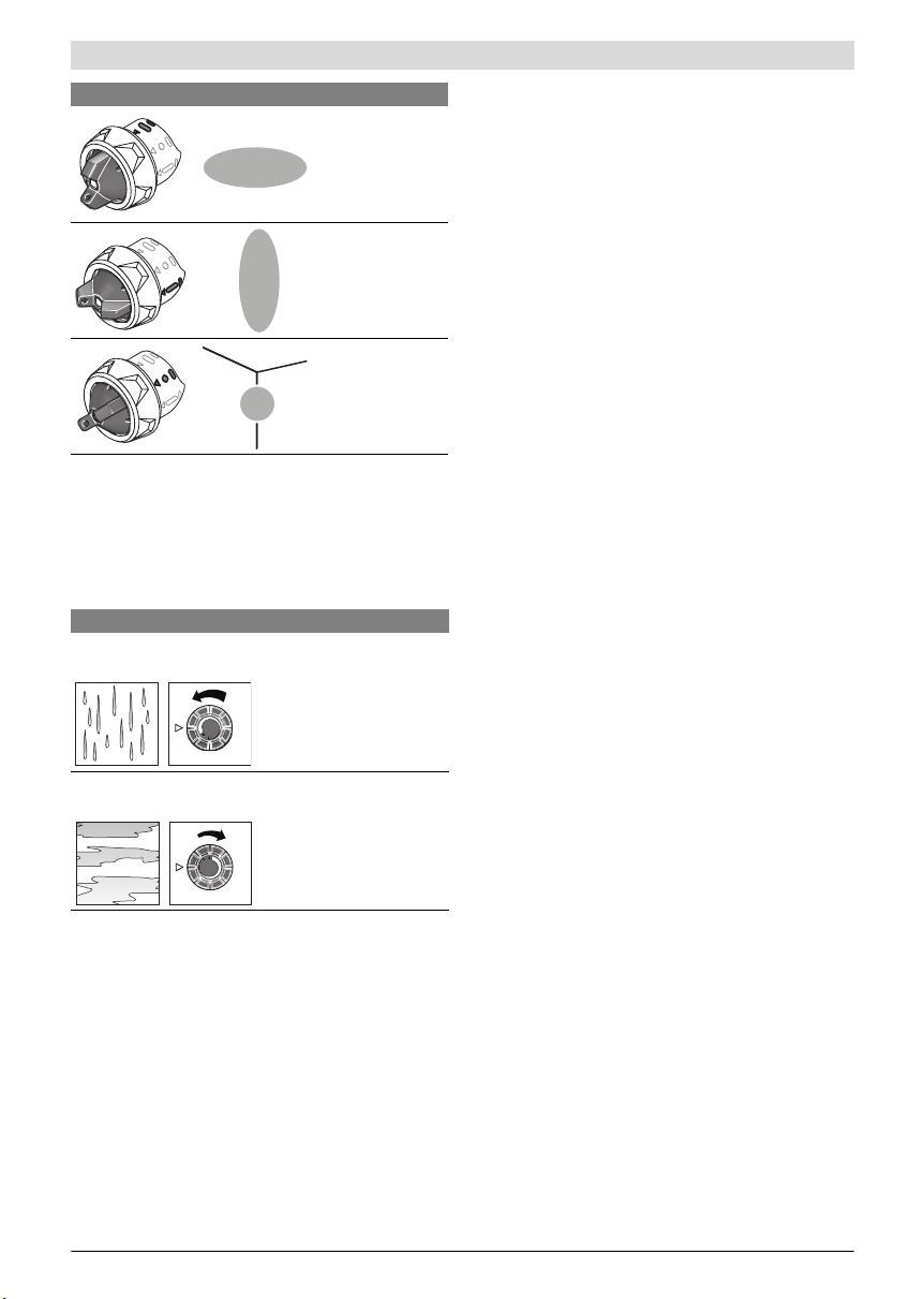
Sprühbild einstellen
Betätigen Sie nie den Bedienschalter 6, während Sie
die Luftkappe 2 verstellen.
– Drehen sie die Luftkappe 2 in die gewünschte Position.
Luftkappe Sprühstrahl Anwendung
waagrechter Flachstrahl für vertikale
Arbeitsrichtung
senkrechter Flachstrahl für horizontale Arbeitsrichtung
Rundstrahl für
Ecken, Kanten und
schwer zugängliche
Stellen
Sprühmaterialmenge einstellen (siehe Bild G)
(PAINTVolume)
– Drehen Sie das Stellrad 5, um die gewünschte Sprühmate-
rialmenge einzustellen:
–: minimale Sprühmaterialmenge,
+: maximale Sprühmaterialmenge.
Sprühmaterialmenge Einstellung
Zu viel Sprühmaterial auf der
Sprühfläche:
Die Sprühmaterialmenge
muss verringert werden.
– Drehen Sie das Stellrad 5
Richtung –.
Sprühmaterialmenge Einstellung
Zu wenig Sprühmaterial auf
der Sprühfläche:
Die Sprühmaterialmenge
muss erhöht werden.
– Drehen Sie das Stellrad 5
Richtung +.
Arbeitspausen und Transport (siehe Bilder H– I)
Zum einfachen Transport des Feinsprühsystem s ist an der Basiseinheit ein Tragegriff 21 und ein Tragegurt 22 angebracht.
Während des Arbeitens können Sie sich die Basiseinheit 19
mit Hilfe des Tragegurts 22 quer über die Schulter hängen.
In Arbeitspausen kann die Sprühpistole 1 auf einer ebenen
Arbeitsfläche abgestellt werden. Es kann kein Sprühmaterial
auslaufen.
Stellen Sie die mit Sprühmaterial befüllte Sprühpistole
immer aufrecht auf eine ebene Fläche. Aus einer liegen-
den Sprühpistole kann Sprühmaterial auslaufen.
Wartung und Service
Wartung und Reinigung
Ziehen Sie vor allen Arbeiten am Elektrowerkzeug den
Netzstecker aus der Steckdose.
Reinigen Sie gründlich nach jedem Gebrauch die Ein-
zelteile des Feinsprühsystems, besonders alle farbführenden Bauteile. Eine sachgemäße Reinigung ist Voraus-
setzung für den einwandfreien und sicheren Betrieb der
Sprühpistole. Bei fehlender oder unsachgemäßer Reinigung werden keine Gewährleistungsansprüche übernommen.
Wenn ein Ersatz der Anschlussleitung erforderlich ist, dann
ist dies von Bosch oder einer autorisierten Kundendienststelle für Bosch-Elektrowerkzeuge auszuführen, um Sicherheitsgefährdungen zu vermeiden.
Luftfilter reinigen (siehe Bild J)
Der Luftfilter 26 muss gelegentlich gereinigt werden. Ist der
Luftfilter stark verschmutzt, muss er gewechselt werden.
– Öffnen Sie die Luftfilterabdeckung 23.
– Entnehmen Sie den Luftfilter 26.
– Leichte Verschmutzung:
Klopfen Sie den Luftfilter 26 aus.
oder
Starke Verschmutzung:
Reinigen Sie den Luftfilter 26 unter fließendem Wasser
und lassen Sie ihn anschließend gut trocknen, um Schimmelbildung zu vermeiden.
oder
Wechseln Sie den Luftfilter 26 aus.
– Setzen Sie den Luftfilter wieder ein.
– Schließen Sie die Luftfilterabdeckung 23 wieder.
2 609 007 770 | (16.9.14) Bosch Power Tools

Feinsprühsystem reinigen (siehe Bild K)
Reinigen Sie die Sprühpistole und den Behälter für das
Sprühmaterial immer mit dem entsprechenden Verdünnungsmittel (Lösemittel oder Wasser) für das verwendete
Sprühmaterial.
Reinigen Sie die Düsen- und Luftbohrungen der Sprühpistole
niemals mit spitzen Gegenständen.
– Schalten Sie die Basiseinheit 19 aus.
– Entfernen Sie sowohl von der Basiseinheit 19 als auch von
der Sprühpistole 1 den Luftschlauch 17 (Vierteldrehung
des Bajonettverschlusses 18 gegen den Uhrzeigersinn;
Bajonettverschluss 18 aus dem Anschluss 4/24 ziehen).
– Reinigen Sie die Basiseinheit gegebenenfalls mit einem mit
Verdünnungsmittel befeuchteten Tuch und entfernen Sie
anschließend die Basiseinheit 19 und den Luftschlauch 17
aus der unmittelbaren Reinigungsumgebung.
– Drücken Sie den Bedienschalter 6 der Sprühpistole, damit
das Sprühmaterial in den Behälter zurücklaufen kann.
– Schrauben Sie den Behälter 7 ab und leeren Sie das restli-
che Sprühmaterial zurück zum Original-Sprühmaterial.
– Füllen Sie den Behälter 7 zur Hälfte mit dem Verdünnungs-
mittel (Lösemittel oder Wasser) und befestigen Sie ihn
wieder an der Sprühpistole 1.
– Schütteln Sie die Sprühpistole mehrmals.
– Schrauben Sie den Behälter 7 ab und entleeren Sie den
Behälter vollständig in eine leere Materialdose.
– Demontieren Sie die Überwurfmutter 3, die Luftkappe 2,
die Dichtscheibe 11, die verwendete Düsenkappe 9/8 mit
dem O-Ring 10 und das Steigrohr 12 mit der Behälterdichtung 14.
Stellen Sie dabei sicher, dass der O-Ring 10 auf der Düse nkappe bleibt.
Deutsch | 13
– Reinigen Sie in einem Eimer mit Verdünnungsmittel alle
farbführenden Teile mit einer handelsüblichen Spülbürste.
Reinigen Sie auch den Farbkanal 16 der Sprühpistole 1.
– Kontrollieren Sie, ob das Steigrohr 12 mit der Behälter-
dichtung 14 frei von Sprühmaterial und unbeschädigt ist.
Reinigen Sie bei Bedarf die Behälterdichtung 14 nochmals
mit Verdünnungsmittel.
Reinigen Sie die Entlüftungsbohrung
neten Gegenstand.
– Reinigen Sie den Behälter und die Sprühpistole außen mit
einem mit Verdünnungsmittel befeuchteten Tuch.
– Lassen Sie vor dem Zusammenbau alle Teile sorgfältig
trocknen.
– Montieren Sie das Feinsprühsystem wieder in umgekehr-
ter Reihenfolge.
Achten Sie dabei darauf, dass Sie das Steigrohr 12 wieder
bis zum Anschlag auf den Farbkanal 16 schieben und dass
Sie die Behälterdichtung 14 wieder in die Nut des Steigrohrs 12 schieben.
Materialentsorgung
Verdünnungsmittel und Sprühmaterialreste müssen umweltgerecht entsorgt werden. Beachten Sie die Entsorgungshinweise des Herstellers und die örtlichen Vorschriften zur So ndermüllentsorgung.
Umweltschädliche Chemikalien dürfen nicht ins Erdreich, ins
Grundwasser oder in Gewässer gelangen. Schütten Sie umweltschädliche Chemikalien nie in die Kanalisation!
Lagerung
– Bevor Sie das Feinsprühsystem einlagern, reinigen Sie das
Feinsprühsystem gründlich und lassen Sie alle Teile vor
dem Zusammenbau sorgfältig trocknen.
15 mit einem geeig-
Behebung von Störungen
Problem Ursache Abhilfe
Sprühmaterial deckt nicht richtig
Sprühmaterial verläuft nach Auftragen
Zu grobe Zerstäubung
Bosch Power Tools 2 609 007 770 | (16.9.14)
Sprühmaterialmenge zu gering Stellrad 5 Richtung + drehen
Abstand zur Sprühfläche zu groß Sprühabstand verringern
Zu wenig Sprühmaterial auf der Sprühfläche,
zu selten über die Sprühfläche gesprüht
Sprühmaterial zu dickflüssig Sprühmaterial erneut verdünnen und Probe-
Zu viel Sprühmaterial aufgetragen Stellrad 5 Richtung – drehen
Abstand zur Sprühfläche zu gering Sprühabstand vergrößern
Sprühmaterial zu dünnflüssig Original-Sprühmaterial zugeben
Zu oft über dieselbe Stelle gesprüht Farbe abtragen und beim zweiten Sprühver-
Sprühmaterialmenge zu hoch Stellrad 5 Richtung – drehen
PFS 2000: Weiße Düsenkappe 9 montiert
(zu großer Düsendurchmesser)
Düsennadel 13 verschmutzt Düsennadel reinigen
Sprühmaterial zu dickflüssig Sprühmaterial erneut verdünnen und Probe-
Luftfilter 26 stark verschmutzt Luftfilter wechseln
Öfter über die Sprühfläche sprühen
sprühung durchführen
such nicht so oft über eine Stelle sprühen
Graue Düsenkappe 8 montieren
sprühung durchführen

14 | Deutsch
Problem Ursache Abhilfe
Zu starker Farbnebel
Sprühstrahl pulsiert
Sprühmaterial tropft an der Düsenkappe nach
Aus der Düsenkappe tritt kein
Sprühmaterial aus
Kundendienst und Anwendungsberatung
Geben Sie bei allen Rückfragen und Ersatzteilbestellungen
bitte unbedingt die 10-stellige Sachnummer laut Typenschild
des Feinsprühsystems an.
Der Kundendienst beantwortet Ihre Fragen zu Reparatur und
Wartung Ihres Produkts sowie zu Ersatzteilen. Explosionszeichnungen und Informationen zu Ersatzteilen finden Sie
auch unter: www.bosch-pt.com
Das Bosch-Anwendungsberatungs-Team hilft Ihnen gerne bei
Fragen zu unseren Produkten und deren Zubehör.
www.bosch-do-it.de, das Internetportal für Heimwerker und
Gartenfreunde.
www.1-2-do.com
In der Heimwerker-Community 1-2-do.com können Sie
Produkttester werden, Ideen sammeln oder sich mit anderen
Heimwerkern austauschen.
www.dha.de, das komplette Service-Angebot der Deutschen
Heimwerker Akademie.
Deutschland
Robert Bosch GmbH
Servicezentrum Elektrowerkzeuge
Zur Luhne 2
37589 Kalefeld – Willershausen
Zu viel Sprühmaterial aufgetragen Stellrad 5 Richtung – drehen
Abstand zur Sprühfläche zu groß Sprühabstand verringern
Zu wenig Sprühmaterial im Behälter Sprühmaterial nachfüllen
Entlüftungsbohrung 15 am Steigrohr 12 ver-
stopft
Steigrohr 12 lose Steigrohr bis zum Anschlag auf den Farbka-
Düsenkappe 9/8 sitzt locker Düsenkappe 9/8 anziehen
Luftfilter 26 stark verschmutzt Luftfilter wechseln
Sprühmaterial zu dickflüssig Sprühmaterial erneut verdünnen und Probe-
Ablagerung von Sprühmaterial an der Düsenkappe 9/8, der Düsennadel 13 und der Luftkappe 2
Düsenkappe 9/8 sitzt locker Düsenkappe 9/8 anziehen
Steigrohr 12 lose Steigrohr bis zum Anschlag auf den Farbka-
Düsennadel 13 verstopft Düsennadel reinigen
Steigrohr 12 verstopft Steigrohr reinigen
Entlüftungsbohrung 15 am Steigrohr 12 ver-
stopft
Behälterdichtung 14 fehlt oder ist beschä-
digt
Sprühmaterial zu dickflüssig Sprühmaterial erneut verdünnen und Probe-
Sprühmaterial verschmutzt (Farbklumpen) Sprühpistole komplett entleeren und reini-
Unter www.bosch-pt.com können Sie online Ersatzteile bestellen oder Reparaturen anmelden.
Kundendienst: Tel.: (0711) 40040480
Fax: (0711) 40040481
E-Mail: Servicezentrum.Elektrowerkzeuge@de.bosch.com
Anwendungsberatung: Tel.: (0711) 40040480
Fax: (0711) 40040482
E-Mail: Anwendungsberatung.pt@de.bosch.com
Österreich
Unter www.bosch-pt.at können Sie online Ersatzteile bestellen.
Tel.: (01) 797222010
Fax: (01) 797222011
E-Mail: service.elektrowerkzeuge@at.bosch.com
Schweiz
Unter www.bosch-pt.com/ch/de können Sie online Ersatzteile bestellen.
Tel.: (044) 8471511
Fax: (044) 8471551
E-Mail: Aftersales.Service@de.bosch.com
Steigrohr und Entlüftungsbohrung reinigen
nal 16 schieben
sprühung durchführen
Düsenkappe, Düsennadel und Luftkappe rei-
nigen
nal 16 schieben
Steigrohr und Entlüftungsbohrung reinigen
(neue) Behälterdichtung über das Steigrohr
in die Nut schieben
sprühung durchführen
gen; Sprühmaterial beim Befüllen durch Einfüllsieb gießen
2 609 007 770 | (16.9.14) Bosch Power Tools

Luxemburg
Tel.: +32 2 588 0589
Fax: +32 2 588 0595
E-Mail: outillage.gereedschap@be.bosch.com
Entsorgung
Sprühpistole, Elektroeinheit, Zubehör und Verpackungen sollen einer umweltgerechten Wiederverwertung zugeführt werden.
Werfen Sie Elektrowerkzeuge nicht in den Hausmüll!
Nur für EU-Länder:
Gemäß der Europäischen Richtlinie
2012/19/EU über Elektro- und ElektronikAltgeräte und ihrer Umsetzung in national es
Recht müssen nicht mehr gebrauchsfähige
Elektrowerkzeuge getrennt gesammelt und
zugeführt werden.
Änderungen vorbehalten.
einer umweltgerechten Wiederverwertung
English
Safety Notes
General Power Tool Safety Warnings
WARNING
and instructions may result in electric shock, fire and/or serious injury.
Save all warnings and instructions for future reference.
The term “power tool” in the warnings refers to your mainsoperated (corded) power tool or battery-opera ted (cordless)
power tool.
Work area safety
Keep work area clean and well lit. Cluttered or dark areas
invite accidents.
Do not operate power tools in explosive atmospheres,
such as in the presence of flammable liquids, gases or
dust. Power tools create sparks which may ig nite the dust
or fumes.
Keep children and bystanders away while operating a
power tool. Distractions can cause you to lose control.
Electrical safety
Power tool plugs must match the outlet. Never modify
the plug in any way. Do not use any adapter plugs with
earthed (grounded) power tools. Unmodified plugs and
matching outlets will reduce risk of electric shock.
Avoid body contact with earthed or grounded surfaces,
such as pipes, radiators, ranges and refrigerators.
There is an increased risk of electric shock if your body is
earthed or grounded.
Read all safety warnings and all instructions. Failure to follow the warnings
English | 15
Do not expose power tools to rain or wet conditions.
Water entering a power tool will increa se the risk of electric
shock.
Do not abuse the cord. Never use the cord for carrying,
pulling or unplugging the power tool. Keep cord away
from heat, oil, sharp edges and moving parts. Damaged
or entangled cords increase the risk of electric shock.
When operating a power tool outdoors, use an exten-
sion cord suitable for outdoor use. Use of a cord suit able
for outdoor use reduces the risk of electric shock.
If operating a power tool in a damp location is unavoid-
able, use a residual current device (RCD) protected
supply. Use of an RCD reduces the risk of electric shock.
Personal safety
Stay alert, watch what you are doing and use common
sense when operating a power tool. Do not use a power
tool while you are tired or under the influence of drugs,
alcohol or medication. A moment of inattention while op-
erating power tools may result in serious personal injury.
Use personal protective equipment. Always wear eye
protection. Protective equipment such as dust mask,
non-skid safety shoes, hard hat, or hearing protection
used for appropriate conditions will reduce personal injuries.
Prevent unintentional starting. Ensure the switch is in
the off-position before connecting to power source
and/or battery pack, picking up or carrying the tool.
Carrying power tools with your finger on the switch or energising power tools that have the switch on invites accidents.
Remove any adjusting key or wrench before turning
the power tool on. A wrench or a key left attached to a ro-
tating part of the power tool may result in personal injury.
Do not overreach. Keep proper footing and balance at
all times. This enables better control of the power tool in
unexpected situations.
Dress properly. Do not wear loose clothing or jewel-
lery. Keep your hair, clothing and gloves away from
moving parts. Loose clothes, jewellery or long hair can be
caught in moving parts.
If devices are provided for the connection of dust ex-
traction and collection facilities, ensure these are connected and properly used. Use of dust collection can re-
duce dust-related hazards.
Power tool use and care
Do not force the power tool. Use the correct power tool
for your application. The correct power tool will do the
job better and safer at the rate for which it was designed.
Do not use the power tool if the switch does not turn it
on and off. Any power tool that cannot be controlled with
the switch is dangerous and must be repaired.
Disconnect the plug from the power source and/or the
battery pack from the power tool before making any
adjustments, changing accessories, or storing power
tools. Such preventive safety measures reduce the risk of
starting the power tool accidentally.
Bosch Power Tools 2 609 007 770 | (16.9.14)

16 | English
Store idle power tools out of the reach of children and
do not allow persons unfamiliar with the power tool or
these instructions to operate the power tool. Power
tools are dangerous in the hands of untrained users.
Maintain power tools. Check for misalignment or bind-
ing of moving parts, breakage of parts and any other
condition that may affect the power tool’s operation. I f
damaged, have the power tool repaired before use.
Many accidents are caused by poorly maintained power
tools.
Keep cutting tools sharp and clean. Properly maintained
cutting tools with sharp cutting edges are less likely to bind
and are easier to control.
Use the power tool, accessories and tool bits etc. in ac-
cordance with these instructions, taking into account
the working conditions and the work to be performed.
Use of the power tool for operations different from those
intended could result in a hazardous situation.
Service
Have your power tool serviced by a qualified repair per-
son using only identical replacement parts. This will en-
sure that the safety of the power tool is maintained.
Safety Warnings for Fine-spray Systems
Keep area clean, well lit and free of paint or solvent
containers, rags, and other flammable materials.
Spontaneous combustion may occur. Fire extinguisher
equipment shall be present and working at all times.
Provide for good ventilation in the spraying area and
for sufficient fresh air in the complete room. Evaporat-
ing inflammable solvents create an explosive environment.
Do not spray and clean with materials that have a flash
point of less than 55 °C. Use materials based o n water,
non-volatile hydrocarbons or similar materials. Volatile
evaporating solvents create an explosive environment.
Do not spray in the vicinity of ignition sources, such as
static electricity sparks, open flames, pilot lights, hot
objects, engines/motors, cigarettes and sparks from
plugging in or unplugging power cords or operating
switches. Such spark sources can ignite the spraying vi-
cinity/environment.
Do not spray any liquid of unknown hazard potential.
Unknown materials can create hazardous conditions.
Wear additional protective equipment such as appro-
priate protective gloves and protective masks or respirators when spraying or handling chemicals. Wearing
protective equipment for the appropriate conditions reduces the exposure to hazardous substances.
Be aware of possible hazards from the spray material.
Observe the information on drums/tanks/tins as well
as manufacturer information of the spray material, including the request to wear personal protective equipment. The manufacturer's instructions are to be observed
in order to red uce the risk of fire as well as injuries caused
through toxins, carcinogens, etc.
Keep the plug of the mains cord and the trigger switch
of the spray gun clear of paint and other fluids. Never
hold the cord by its connectors to support it. Failure to
follow the instruction can lead to electric shock.
Supervise children. This will ensure that children do not
play with the fine-spray system.
Products sold in GB only: Your product is fitted with a
BS 1363/A approved electric plug with internal fuse (ASTA
approved to BS 1362).
If the plug is not suitable for your socket outlets, it should be
cut off and an appropriate plug fitted in its place by an authorised customer service agent. The replacement plug should
have the same fuse rating as the original plug.
The severed plug must be disposed of to avoid a possible
shock hazard and should never be inserted into a mains socket elsewhere.
Products sold in AUS and NZ only: Use a residual current device (RCD) with a rated residual current of 30 mA or less.
Product Description and Specifications
Read all safety warnings and all instructions. Failure to follow the warnings and in-
structions may result in electric shock, fire
and/or serious injury.
Intended Use
PFS 1000
The power tool is only intended for atomising solvent-based
and water-dilutable lacquers, glazes, primers, clear lacquers,
automotive top coats, wood stains and oils.
The power tool can also be used to spray more highly diluted
emulsion and latex paints.
The power tool is not suitable for use with caustic solutions,
acidic coating materials, spray material containing grains or
solids, and spatter and drip resistant materials.
PFS 2000
The power tool is only intended for spraying emulsion and latex paints, solvent-based and water-dilutable lacquers, glazes, primers, clear lacquers, wood stains and oils (ALLPaint).
The power tool is not suitable for spraying caustic solutions,
acidic coating materials and house paints.
2 609 007 770 | (16.9.14) Bosch Power Tools

English | 17
Product Features
The numbering of the components shown refers to the representation of the power tool on the graphic pages.
1Spray gun
2 Air cap
3 Union nut
4 Hose port (spray gun)
5 Thumbwheel for spraying capacity
6 Trigger switch
7 Container for spray material
8 Nozzle cap (grey: for a “wood” application)
9 Nozzle cap (white: for a “wall” application)
(PFS 2000)
10 O-ring
11 Gasket
12 Suction tube
13 Nozzle needle
14 Container seal
15 Ventilation hole
16 Paint channel
17 Air hose
18 Bayonet lock
19 Base unit
20 On/Off switch
21 Carrying handle
22 Carrying strap
23 Air filter cover
24 Hose connection (base unit)
25 Eyelet for carrying strap
26 Air filter
*Accessories shown or described are not part of the standard delivery scope of the product. A complete overview of accessories
can be found in our accessories program.
Technical Data
Fine-spray System PFS 1000 PFS 2000
Article number
Rated power input
Spraying capacity
Required time for application of paint on 2 m
2
ml/min 100 200
Container capacity for spray material
Nozzle cap 8 (grey)
– “Wood” application:
Spraying solvent-based and water-dilutable lacquers, glazes, primers,
clear lacquers, wood stains and oils
Nozzle cap 9 (white)
– “Wall” application:
Spraying emulsion and latex paints –
Length of air hose
Weight according to EPTA-Procedure 01/2003
Protection class
The values given are valid for a nominal voltage [U] of 230 V. For different vol tages and models for specific countries, these values can vary.
Noise/Vibration Information
Sound emission values determined according to
EN 60745-1, EN 50580.
Typically the A-weighted sound pressure level of the product
is 79 dB(A). Uncertainty K =3 dB.
The noise level when working can exceed 80 dB(A).
Wear hearing protection!
Vibration total values a
determined according to EN 60745:
<2,5m/s2, K= 1,5 m/s2.
a
h
The vibration level given in this information sheet has been
measured in accordance with a standardised test given in
(triax vector sum) and uncertainty K
h
applications, with different accessories or insertion tools or is
poorly maintained, the vibration emission may differ. This
may significantly increase the exposure level over the total
working period.
An estimation of the level of exposure to vibration should also
take into account the times when the tool is switched off or
when it is running but not actually doing the job. This may significantly reduce the exposure level over the total working
period.
Identify additional safety measures to protect the operator
from the effects of vibration such as: maintain the tool and the
accessories, keep the hands warm, organisation of work pat-
terns.
EN 60745 and may be used to compare one tool with another. It may be used for a preliminary assessment of exposure.
The declared vibration emission level represents the main a pplications of the tool. However if the tool is used for different
3 603 B07 0.. 3 603 B07 3..
W 410 440
min 2 1,3
ml 800 800
m1.251.25
kg 2.0 2.0
/II /II
Bosch Power Tools 2 609 007 770 | (16.9.14)
18 | English
Declaration of Conformity
We declare under our sole responsibility that the product described under “Technical Data” is in conformity with all relevant provisions of the directives 2011/65/EU, 2014/30/EU,
2006/42/EC including their amendments and complies with
the following standards: EN 60745-1, EN 50580.
Technical file (2006/42/EC) at:
Robert Bosch GmbH, PT/ETM9,
70764 Leinfelden-Echterdingen, GERMANY
Henk Becker
Executive Vice President
Engineering
Robert Bosch GmbH, Power Tools Division
70764 Leinfelden-Echterdingen, GERMANY
Leinfelden, 05.06.2014
Helmut Heinzelmann
Head of Product Certification
PT/ETM9
Assembly
Before any work on the machine itself, pull the mains
plug.
Ensure that the spray gun and base unit are assembled
completely and with all seals. Only this will ensure the
function and safety of the fine-spray system.
Connecting the Air Hose (see figures A1– A2)
Connecting the base unit:
– Insert a bayonet lock 18 of the air hose securely into the
slots in the base unit port 24 according to the arrow marks.
– Turn the bayonet lock a quarter turn clockwise.
Connecting to the spray gun:
– Insert the second bayonet lock 18 of the air hose securely
into the slots in the spray gun port 4 according to the arrow
marks.
– Turn the bayonet lock a quarter turn clockwise.
Note: Remove the air hose 17 before pouring in spray materi-
al (quarter turn of the bayonet lock 18 counterclockwise; pull
the bayonet lock 18 out of the port 4).
Fastening the Carrying Strap (see figure B)
In order to reach all surfaces to be sprayed and maintain flexibility, you can sling on the base unit with the carrying strap
22.
– Attach one strap end to each eyelet 25.
Changing the Nozzle Cap (PFS 2000)
(see figure C)
Note: Check the spray material by stirring it before selecting
the nozzle cap. Thin-viscosity material (e.g. wood paint) or diluted material can be sprayed better with the grey nozzle cap
8. Thicker-viscosity material (e.g. wood lacquer or wall paint)
can be sprayed better with the white nozzle cap 9.
– To change the nozzle cap, unscrew the union nut 3.
– Pull off the air cap 2 and the gasket 11.
– Unscrew the mounted nozzle cap.
When doing so, ensure that the O-ring 10 remains on the
nozzle cap.
– Screw the required nozzle cap into the thr ead in the spray
gun.
–Put the air cap 2 with the gasket 11 on the nozzle cap and
tighten it with the union nut 3.
Operation
Before any work on the machine itself, pull the mains
plug.
Preparing for Operation
Spraying on the sides of water bodies (lakes, rivers,
etc.) or neighbouring surfaces in the direct catchment
area is not permitted.
When purchasing paint, varnish and spray material, pay at-
tention to their environmen tal compatibility.
Preparing the Spray Surface
The spray surface must be clean, dry and grease-free.
– Roughen smooth surfaces and then remove the sanding
dust.
When spraying, all non-covered surfaces can be soiled by the
spray mist. Therefore, thoroughly prepare the area around
the surface to be sprayed:
– Cover or mask off floors, furnishings, doors, windows as
well as door and window frames, etc.
Preparing the Spray Material
– Stir the spray material thoroughly.
– Dilute the spray material if necessary.
Spray material Recommended
Wood stains, oils, glazes, impregnations, anti-rust primers
Solvent-dilutable or water-dilutable
lacquers, primers, radiator lacquers,
thick-coat glazes
Emulsion paint, latex paint minimum 10 %
When diluting, pay attention that the spray material
and the diluting agent correspond. When using a faulty
diluting agent, lumps can develop that can lead to clogging
of the spray gun.
When diluting the spray material, make sure that the
flash point of the mixture is above 55 °C again after diluting. Diluting e.g. solvent-based lacquers lowers the
flash point.
dilution
0%
10 %
2 609 007 770 | (16.9.14) Bosch Power Tools
Filling in Spray Material (see figures D1 –D2)
Note: Remove the air hose 17 before pouring in spray materi-
al (quarter turn of the bayonet lock 18 counterclockwise; pull
the bayonet lock 18 out of the port 4).
– Unscrew the container 7 from the spray gun.
– Pour the spray material into the container 7 up to no more
than the 800 mark.
– Turn the suction tube 12 so that the spray material can be
sprayed with almost no residue:
For spray jobs on horizontal
surfaces/objects
For spray jobs overhead toward the rear in handle
– Carry out a test-spray run on a test surface. (see “Spray-
ing”, page 19)
When the spraying pattern is perfect, start the spray job.
or
When the spraying result is not satisfactory or when no paint
comes out, please continue as described under “Correction of
Malfunctions” on page 21.
toward the front in nozzle/
air cap direction
direction
Starting Operation (see figure E)
Observe the mains voltage! The voltage of the power
source must correspond with the data on the type plate of
the machine.
Pay attention that the base unit cannot draw in dust or
other contamination during operation.
Make sure never to spray on the base unit.
Stop spraying if fluid escapes from places other than
the intended nozzle during spraying, and restore the
spray gun to its proper condition. There is a risk of elec-
tric shock.
Do not direct the fine-spray system against yourself,
other persons or animals.
Switching On
To save energy, only switch the fine-spray system on when
you are using it.
– PFS 2000: Check whether the correct nozzle cap is
mounted (see “Changing the Nozzle Cap”, page 18).
– Plug the mains plug into a socket outlet.
– Grasp the spray gun by the handle and point it at the spray
surface.
– Slide the On/Off switch 20 forwards.
– Pull the trigger switch 6 on the spray gun.
Note: Air always flows out at the air cap 2 when the base unit
is switched on.
Switching Off
– Let go of the trigger switch 6 and slide the On/Off switch
20 backwards.
– Pull the mains plug from the socket outlet.
English | 19
Working Advice
Spraying (see figure F)
Note: Observe the wind direction when operating the power
tool outdoors.
– Firstly, carry out a test-spray run and adjust the spray pat-
tern and the spray material quantity according to the spray
material. (For adjustments, see the following sections)
– Be absolutely sure to hold the spray gun at a consistent dis-
tance of 20–25 cm perpendicular to the spray object.
– Begin the spraying procedure outside the target area.
– Move the spray gun evenly cross-w ise or up-and-down, de-
pending on the spray pattern setting.
An even surface quality is achieved when the paths overlap
by 4 – 5 cm.
– When spraying horizontal objects or spraying overhead,
hold the spray gun at a slight angle and back away from the
sprayed surface.
Risk of stumbling! Pay attention to possible obstacles
in the room.
– Avoid interruptions within the spray surface.
Guiding the spray gun evenly will provide uniform surface
quality.
Non-uniform clearance and spray angle lead to heavy forma-
tion of paint mist and thus to an uneven surface.
– End the spraying procedure outside the target area.
Never completely empty the container for the spray material
by spraying. If the suction tube is no longer immersed in the
spray material, the spray jet will be interrupted and this will
result in an inconsistent surface.
If the spray material settles on the nozzle cap and air cap,
clean both parts with the diluting agent used.
Adjusting the Spray Pattern
Never actuate the trigger switch 6 while adjusting the
air cap 2.
–Turn the air cap 2 to the requested position.
Bosch Power Tools 2 609 007 770 | (16.9.14)
20 | English
Air cap Spray jet pattern Application
Horizontal flat jet
for vertical working
direction
Vertical flat jet for
horizontal working
direction
Round jet for corners, edges and
hard to reach locations
Adjusting the Spraying Capacity (see figure G)
(PAINTVolume)
– To adjust the requested spraying capacity, turn the thumb-
wheel 5:
–: Min. spraying capacity,
+: Max. spraying capacity.
Spraying capacity Adjustment
Too much material on target area:
Not enough material on target
area:
The spraying capacity must
be reduced.
– Turn the thumbwheel 5 in
direction –.
The spraying capacity must
be increased.
– Turn the thumbwheel 5 in
direction +.
Work Breaks and Transport (see figures H– I)
A carrying handle 21 and a carrying strap 22 are fitted to the
base unit to enable easy transport of the fine-spray system.
You can hang the base unit 19 across your shoulder during
work using the carrying strap 22.
The spray gun 1 can be put down on a flat work surface during
breaks. No spray material can leak out.
Always put the spray gun upright on a flat surface when
it is filled with spray material. Spray material can leak
out from a spray gun if it is lying down.
Maintenance and Service
Maintenance and Cleaning
Before any work on the machine itself, pull the mains
plug.
Thoroughly clean the individual parts of the fine-spray
system after each use, especially all paint-carrying
components. Proper cleaning is a prerequisite for fault-
less and safe operation of the spray gun. No warranty
claims will be accepted if cleaning has not been done at all
or has not been done properly.
If the replacement of the s upply cord is necessary, this has to
be done by Bosch or an authorized Bosch service agent in order to avoid a safety hazard.
Cleaning the Air Filter (see figure J)
The air filter 26 must be cleaned occasionally. The air filter
must be replaced if it is heavily soiled.
– Open the air filter cover 23.
– Remove the air filter 26.
– Light soiling:
Tap the air filter 26 to empty it.
or
Heavy soiling:
Clean the air filter 26 under running water and then leave it
dry thoroughly to prevent mould from forming.
or
Replace the air filter 26.
– Reinsert the air filter.
– Close the air filter cover 23 again.
Cleaning the Fine-spray System (see figure K)
Always clean the spray gun and the container with the respective diluting agent (pain t thinner or water) for the spray material being used.
Never clean the nozzle and air holes in the spray gun with
pointed objects.
– Switch the base unit 19 off.
– Remove the air hose 17 both from the base unit 19 and
from the spray gun 1 (quarter turn of the bayonet lock 18
counterclockwise; pull the bayonet lock 18 out of the port
4/24).
– Clean the base unit if necessary with a cloth moistened
with diluting agent and then remove the base unit 19 and
the air hose 17 from the immediate cleaning environment.
– Press the trigger switch 6 on the spray gun so that the
spray material can flow back in to the container.
– Unscrew the container 7 and empty the remaining spray
material back into the original spray material.
– Fill the container 7 halfway with the diluting agent (solvent
or water) and fit it to the spray gun 1 again.
– Shake the spray gun several times.
– Unscrew the container 7 and empty the container com-
pletely into an empty material tin.
2 609 007 770 | (16.9.14) Bosch Power Tools

– Remove the union nut 3, the air cap 2, the gasket 11, the
nozzle cap used 9/8 with the O-ring 10 and the suction
tube 12 with the container seal 14.
When doing so, ensure that the O-ring 10 remains on the
nozzle cap.
– Clean all paint-carrying parts in a bucket with diluting agent
using a standard washing-up brush.
Also clean the paint channel 16 of the spray gun 1.
– Check if the suction tube 12 and the container seal 14 are
free of spray material and undamaged.
If required, clean the container seal 14 again with diluting
agent.
Clean the ventilation hole 15 using a suitable object.
– Clean the outside of the container and the spray gun with a
cloth moistened in paint thinner.
– Before mounting, allow all components to dry thoroughly.
– Reassemble the fine-spray system in reverse order.
When doing so, make sure that you slide the suction tube
12 all the way back onto the paint channel 16 and that you
slide the container seal 14 back into the groove of the suc-
tion tube 12.
Material Disposal
Diluting agent and remainders of spray material must be disposed of in an environmentally-friendly manner. Observe the
manufacturer’s disposal in formation and the local regulations
for disposal of hazardous waste.
Chemicals harmful to the environment may not be disposed
of into soil, groundwater or bodies of water. Never pour
chemicals harmful to the environment into the sewerage system!
Storage
– Before putting the fine-spray system into storage, thor-
oughly clean the fine-spray system and allow all parts to
dry completely before assembling them.
Correction of Malfunctions
Problem Cause Corrective Measure
Spray material does not cover
properly
Spray material runs off after
coating
Atomisation too coarse
Excessive paint mist
Spray jet pulsates
Spraying capacity too low Turn thumbwheel 5 in direction +
Clearance to target area too large Reduce spray distance
Not enough spray material on target area,
too few spray paths sprayed over target area
Spray material too viscous Dilute t he spray material again and carry out
Too much spray material applied Turn thumbwheel 5 in direction –
Clearance to target area too close Increase spray distance
Viscosity of spray material too low Add original spray material
Spray material applied too often over same
spot
Spraying capacity too high Turn thumbwheel 5 in direction –
PFS 2000: White nozzle cap 9 mounted
(nozzle diameter too large)
Nozzle needle 13 soiled Clean nozzle needle
Spray material too viscous Dilute t he spray material again and carry out
Air filter 26 heavily soiled Changing the Air Filter
Too much spray material applied Turn thumbwheel 5 in direction –
Clearance to spray surface too large Reduce spray distance
Not enough spray material in container Refill spray material
Ventilation hole 15 on suction tube 12
clogged
Suction tube 12 loose Slide the suction tube all the way onto the
Nozzle cap 9/8 loose Tighten the nozzle cap 9/8
Air filter 26 heavily soiled Change the air filter
Spray material too viscous Dilute t he spray material again and carry out
Apply more spray paths over target area
a test-spray run
Remove spray material; reduce number of
spray paths over same spot
Mount the grey nozzle cap 8
a test-spray run
Clean the suction tube and the ventilation
hole
paint channel 16
a test-spray run
English | 21
Bosch Power Tools 2 609 007 770 | (16.9.14)

22 | English
Problem Cause Corrective Measure
Spray material dripping at the
nozzle cap
No spray material coming out of the
nozzle cap
Deposit of spray material on the nozzle cap
9/8, the nozzle needle 13 and the air cap 2
Nozzle cap 9/8 loose Tighten the nozzle cap 9/8
Suction tube 12 loose Slide the suction tube all the way onto the
Nozzle needle 13 clogged Clean nozzle needle
Suction tube 12 clogged Clean suction tube
Ventilation hole 15 on suction tube 12
clogged
Container seal 14 missing or damaged Slide a (new) container seal over the suction
Spray material too viscous Dilute t he spray material again and carry out
Spray material dirty (lumps of paint) Completely empty and clean the spray gun;
After-sales Service and Application Service
In all correspondence and spare parts orders, please always
include the 10-digit article number given on the type plate of
the fine-spray system.
Our after-sales service responds to your questions concerning maintenance and repair of your product as well as spare
parts. Exploded views and information on spare parts can also be found under:
www.bosch-pt.com
Bosch’s application service team will gladly answer questions
concerning our products and their accessories.
Great Britain
Robert Bosch Ltd. (B.S.C.)
P.O. Box 98
Broadwater Park
North Orbital Road
Denham
Uxbridge
UB 9 5HJ
At www.bosch-pt.co.uk you can order spare parts or arrange
the collection of a product in need of servicing or repair.
Tel. Service: (0844) 7360109
E-Mail: boschservicecentre@bosch.com
Ireland
Origo Ltd.
Unit 23 Magna Drive
Magna Business Park
City West
Dublin 24
Tel. Service: (01) 4666700
Fax: (01) 4666888
Australia, New Zealand and Pacific Islands
Robert Bosch Australia Pty. Ltd.
Power Tools
Locked Bag 66
Clayton South VIC 3169
Customer Contact Center
Inside Australia:
Phone: (01300) 307044
Fax: (01300) 307045
Inside New Zealand:
Phone: (0800) 543353
Fax: (0800) 428570
Outside AU and NZ:
Phone: +61 3 95415555
www.bosch.com.au
Republic of South Africa
Customer service
Hotline: (011) 6519600
Gauteng – BSC Service Centre
35 Roper Street, New Centre
Johannesburg
Tel.: (011) 4939375
Fax: (011) 4930126
E-Mail: bsctools@icon.co.za
KZN – BSC Service Centre
Unit E, Almar Centre
143 Crompton Street
Pinetown
Tel.: (031) 7012120
Fax: (031) 7012446
E-Mail: bsc.dur@za.bosch.com
Western Cape – BSC Service Centre
Democracy Way, Prosperity Park
Milnerton
Tel.: (021) 5512577
Fax: (021) 5513223
E-Mail: bsc@zsd.co.za
Bosch Headquarters
Midrand, Gauteng
Tel.: (011) 6519600
Fax: (011) 6519880
E-Mail: rbsa-hq.pts@za.bosch.com
Clean the nozzle cap, nozzle needle and air
cap
paint channel 16
Clean the suction tube and the ventilation
hole
tube into the groove
a test-spray run
pour the spray material through the filling
sieve when filling
2 609 007 770 | (16.9.14) Bosch Power Tools

Français | 23
Disposal
Spray gun, electrical unit, accessories and packaging should
be sorted for environmental-friendly recycling.
Do not dispose of power tools into household waste!
Only for EC countries:
According to the European Directive
2012/19/EU for Waste Electrical and Electronic Equipment and its implementation
into national right, power tools that are no
longer usable must be collected separately
rect manner.
Subject to change without notice.
and disposed of in an environmentally cor-
Français
Avertissements de sécurité
Avertissements de sécurité généraux pour l’outil
AVERTISSEMENT
tructions. Ne pas suivre les avertissements et instructions
peut donner lieu à un choc électrique, un incendie et/ou une
blessure sérieuse.
Conserver tous les avertissements et toutes les instructions pour pouvoir s’y reporter ultérieurement.
Le terme « outil » dans les avertissements fait référence à
votre outil électrique alimenté par le secteur (avec cordon
d’alimentation) ou votre outil fonctionnant sur batterie (sans
cordon d’alimentation).
Sécurité de la zone de travail
Conserver la zone de travail propre et bien éclairée. Les
zones en désordre ou sombres sont propices aux accidents.
Ne pas faire fonctionner les outils électriques en at-
mosphère explosive, par exemple en présence de liquides inflammables, de gaz ou de poussières. Les ou-
tils électriques produisent des étincelles qui peuvent
enflammer les poussières ou les fumées.
Maintenir les enfants et les personnes présentes à
l’écart pendant l’utilisation de l’outil. Les distractions
peuvent vous faire perdre le contrôle de l’outil.
Sécurité électrique
Il faut que les fiches de l’outil électrique soient adap-
tées au socle. Ne jamais modifier la fiche de quelque façon que ce soit. Ne pas utiliser d’adaptateurs avec des
outils à branchement de terre. Des fiches non modifiées
et des socles adaptés réduiront le risque de choc électrique.
Eviter tout contact du corps avec des surfaces reliées à
la terre telles que les tuyaux, les radiateurs, les cuisinières et les réfrigérateurs. Il existe un risque accru de
choc électrique si votre corps est relié à la terre.
Bosch Power Tools 2 609 007 770 | (16.9.14)
Lire tous les avertissements
de sécurité et toutes les ins-
Ne pas exposer les outils à la pluie ou à des conditions
humides. La pénétration d’eau à l’intérieur d’un outil aug-
mentera le risque de choc électrique.
Ne pa s m alt ra it er l e c or do n. Ne j am ai s u til is er le co rdo n
pour porter, tirer ou débrancher l’outil. Maintenir le
cordon à l’écart de la chaleur, du lubrifiant, des arêtes
ou des parties en mouvement. Les cordons endommagés
ou emmêlés augmentent le risque de choc électrique.
Lorsqu’on utilise un outil à l’extérieur, utiliser un pro-
longateur adapté à l’utilisation extérieure. L’utilisation
d’un cordon adapté à l’utilisation extérieure réduit le risque
de choc électrique.
Si l’usage d’un outil dans un emplacement humide est
inévitable, utiliser une alimentation protégée par un
dispositif à courant différentiel résiduel (RCD). L’usage
d’un RCD réduit le risque de choc électrique.
Sécurité des personnes
Rester vigilant, regarder ce que vous êtes en train de
faire et faire preuve de bon sens dans l’utilisation de
l’outil. Ne pas utiliser un outil lorsque vous êtes fatigué
ou sous l’emprise de drogues, d’alcool ou de médica-
ments. Un moment d’inattention en cours d’utilisation
d’un outil peut entraîner des blessures graves des per-
sonnes.
Utiliser un équipement de sécurité. Toujours porter
une protection pour les yeux. Les équipements de sécu-
rité tels que les masques contre les poussières, les chaus-
sures de sécurité antidérapantes, les casques ou les pro-
tections acoustiques utilisés pour les conditions
appropriées réduiront les blessures des personnes.
Eviter tout démarrage intempestif. S’assurer que l’in-
terrupteur est en position arrêt avant de brancher l’ou-
til au secteur et/ou au bloc de batteries, de le ramasser
ou de le porter. Porter les outils en ayant le doigt sur l’in-
terrupteur ou brancher des outils dont l’interrupteur est en
position marche est source d’accidents.
Retirer toute clé de réglage avant de mettre l’outil en
marche. Une clé laissée fixée sur une partie tournante de
l’outil peut donner lieu à des blessures de personnes.
Ne pas se précipiter. Garder une position et un équi-
libre adaptés à tout moment. Cela permet un meilleur
contrôle de l’outil dans des situations inattendues.
S’habiller de manière adaptée. Ne pas porter de vête-
ments amples ou de bijoux. Garder les cheveux, les vê-
tements et les gants à distance des parties en mouve-
ment. Des vêtements amples, des bijoux ou les cheveux
longs peuvent être pris dans des parties en mouvement.
Si des dispositifs sont fournis pour le raccordement
d’équipements pour l’extraction et la récupération des
poussières, s’assurer qu’ils sont connectés et correcte-
ment utilisés. Utiliser des collecteurs de poussière peut
réduire les risques dus aux poussières.
Utilisation et entretien de l’outil
Ne pas forcer l’outil. Utiliser l’outil adapté à votre appli-
cation. L’outil adapté réalisera mieux le travail et de ma-
nière plus sûre au régime pour lequel il a été construit.

24 | Français
Ne pas utiliser l’outil si l’interrupteur ne permet pas de
passer de l’état de marche à arrêt et vice versa. Tout ou-
til qui ne peut pas être commandé par l’interrupteur est
dangereux et il faut le faire réparer.
Débrancher la fiche de la source d’alimentation en cou-
rant et/ou le bloc de batteries de l’outil avant tout réglage, changement d’accessoires ou avant de ranger
l’outil. De telles mesures de sécurité préventives ré-
duisent le risque de démarrage accidentel de l’outil.
Conserver les outils à l’arrêt hors de la portée des en-
fants et ne pas permettre à des personnes ne connaissant pas l’outil ou les présentes instructions de le faire
fonctionner. Les outils sont dangereux entre les mains
d’utilisateurs novices.
Observer la maintenance de l’outil. Vérifier qu’il n’y a
pas de mauvais alignement ou de blocage des parties
mobiles, des pièces cassées ou toute autre condition
pouvant affecter le fonctionnement de l’outil. En cas de
dommages, faire réparer l’outil avant de l’utiliser. De
nombreux accidents sont dus à des outils mal entretenus.
Garder affûtés et propres les outils permettant de cou-
per. Des outils destinés à couper correctement entretenus
avec des pièces coupantes tranchantes sont moins susceptibles de bloquer et sont plus faciles à contrôler.
Utiliser l’outil, les accessoires et les lames etc., confor-
mément à ces instructions, en tenant compte des
conditions de travail et du travail à réaliser. L’utilisation
de l’outil pour des opérations différentes de celles prévues
pourrait donner lieu à des situations dangereuses.
Maintenance et entretien
Faire entretenir l’outil par un réparateur qualifié utili-
sant uniquement des pièces de rechange identiques.
Cela assurera que la sécurité de l’outil est maintenue.
Consignes de sécurité pour les systèmes de pulvérisation fine
Maintenir la zone de travail propre et bien éclairée et
exempte de pots de peinture ou de solvants, de torchons et d’autres matériaux inflammables. Danger pos-
sible d’auto-inflammation. Tenir à tout temps à disposition
des extincteurs/des équipements et matériels de sapeurspompiers prêts à être mis en service.
Veiller à garantir une bonne aération dans la zone de
pulvérisation et assez d’air frais dans le local entier.
Les solvants inflammables qui se volatilisent génèrent une
ambiance explosive.
Pour la pulvérisation ou le nettoyage, ne pas employer
de produits dont le point d’éclair est inférieur à 55 °C.
Utilisez des produits à base d’eau, d’hydrocarbures peu
volatils ou bien des produits similaires. Les solvants très
volatils créent une atmosphère explosive.
Ne pas pulvériser à proximité de sources d’allumage
telles qu’étincelles d’électricité statique, feux ouverts,
flammes pilotes, objets chauds, moteurs, cigarettes et
étincelles générées par la connexion et déconnexion
de câbles électriques ou la commande d’interrupteurs.
De tels sources d’étincelles peuvent causer un incendie
dans les zones avoisinantes.
Ne pas pulvériser de matériaux dont vous ne savez pas
s’ils présentent un danger. Les matériaux inconnus
peuvent causer des conditions dangereuses.
Porter en plus un équipement de protection indivi-
duelle tels que gants et masques anti-poussières ou
respirateur lors de la pulvérisation ou de la manipula-
tion de produits chimiques. Les équipements de sécurité
pour certaines conditions réduisent l’exposition des per-
sonnes aux substances dangereuses.
Tenir compte des dangers éventuels du produit. Tenir
compte des repères sur le pot ou des informations du
fabricant du produit, y compris de la nécessité de por-
ter un équipement de protection personnel. Respecter
impérativement les indications du fabricant pour réduire le
danger d’incendie ou les blessures causées par les
toxiques, les carcinogènes etc.
Maintenir la fiche du câble de secteur et l’interrupteur
du pistolet-pulvérisateur exempts de peinture et
d’autres liquides. Ne jamais tenir le câble pour soutenir
les connexions. Ne pas suivre les avertissements peut
donner lieu un choc électrique.
Ne laissez pas les enfants sans surveillance. Veillez à ce
que les enfants ne jouent pas avec le système de pulvérisa-
tion fine.
Description et performances du produit
Il est impératif de lire toutes les consignes
de sécurité et toutes les instructions. Le
non-respect des avertissements et instructions indiqués ci-après peut conduire à une
électrocution, un incendie et/ou de graves
blessures.
Utilisation conforme
PFS 1000
L’outil électroportatif n’est conçu que pou r la pulvérisation de
peintures diluables à l’eau à base de solvants, de lasures,
d’apprêts, de vernis, de laques de finition automobiles, de
teintes à bois et d’huiles.
L’outil électroportatif peut aussi être utilisé pour la pulvérisation de peintures à dispersion et au latex très diluées.
L’outil électroportatif ne convient pas pour la pulvérisation de
produits basiques, de produits de revêtement acides, de produits de pulvérisation granuleux ou contenant des substances
solides ou de produits anti-éclaboussure et anti-goutte.
2 609 007 770 | (16.9.14) Bosch Power Tools

Français | 25
PFS 2000
L’outil électroportatif n’est conçu que pou r la pulvérisation de
peintures diluables à l’eau à ba se de solvants, de lasures,
d’apprêts, de vernis, de teintes à bois et d’huiles (ALLPaint).
L’outil électroportatif n’es t pas conçu pour la pulvérisation de
produits basiques, de produits de revêtement acides et de
peintures de façade.
Eléments de l’appareil
La numérotation des éléments de l’appareil se réfère à la représentation de l’outil électroportatif sur les pages graphiques.
1 Pistolet-pulvérisateur
2 Clapet à air
3 Ecrou-raccord
4 Raccord de tuyau (pistolet-pulvérisateur)
5 Molette de présélection de la quantité du produit de pul-
vérisation
6 Interrupteur
7 Récipient pour le produit de pulvérisation
8 Buse (grise : pour applications de type « bois »)
9 Buse (blanche : pour applications de type « murs »)
(PFS 2000)
10 Rondelle élastique
11 Rondelle étanche
12 Tube d’immersion
13 Aiguille de buse
14 Opercule du récipient
15 Orifice d’aération
16 Canal de peinture
17 Tuyau flexible
18 Fermeture à baïonnette
19 Unité de base
20 Interrupteur Marche/Arrêt
21 Poignée
22 Sangle
23 Couvercle du filtre à air
24 Raccord de tuyau (unité de base)
25 Mousqueton de la sangle
26 Filtre à air
*Les access oires décrits ou illustrés ne sont pas tous compris dans
la fourniture. Vous trouverez les accesso ires complets dans notre
programme d’accessoires.
Caractéristiques techniques
Système de pulvérisation fine PFS 1000 PFS 2000
N° d’article
Puissance nominale absorbée
Débit
Temps nécessaire pour 2 m
2
l’application de la peinture min 2 1,3
ml/min 100 200
Volume du récipient pour produit de pulvérisation
Buse 8 (gris)
– Applications de type « bois » :
Pulvérisation de peintures diluables à l’eau à base de solvants, de lasures, d’apprêts, de vernis, de teintes à bois et d’huiles
Buse 9 (blanc)
– Applications de type « mur » :
Pulvérisation de peintures acryliques et latex –
Longueur du tuyau flexible
Poids suivant EPTA-Procedure 01/2003
Classe de protection
Ces indications sont valables pour une tension nominal e de [U] 230 V. Ces indications peuvent varier pour des tensions plus basse s ainsi que pour des
versions spécifiques à certains pays.
Niveau sonore et vibrations
Valeurs d’émissions sonores déterminées selon la norme
EN 60745-1, EN 50580.
Les mesures réelles (A) du niveau de pression acoustique de
l’appareil sont de 79 dB(A). Incertitude K =3 dB.
Lors du travail, le niveau sonore peut dépasser 80 dB(A).
Porter une protection acoustique !
Valeurs totales des vibrations a
axes directionnels) et incertitude K relevées conformément à
la norme EN 60745 : a
Bosch Power Tools 2 609 007 770 | (16.9.14)
(somme vectorielle des trois
h
<2,5m/s2, K = 1,5 m/s2.
h
Le niveau d’oscillation indiqué dans ces instructions d’utilisation a été mesuré conformément à la norme EN 60745 et peut
être utilisé pour une comparaison d’outils électroportatifs. Il
est également approprié pour une estimation préliminaire de
la charge vibratoire.
Le niveau d’oscillation correspond aux utilisations principales
de l’outil électroportatif. Si l’outil électrique est néanmoins
utilisé pour d’autres applications, avec différents accessoires
ou d’autres outils de travail ou s’il est mal entretenu, le niveau
d’oscillation peut être différent. Ceci peut augmenter considérablement la charge vibratoire pendant toute la durée de
3 603 B07 0.. 3 603 B07 3..
W 410 440
ml 800 800
m1,251,25
kg 2,0 2,0
/II /II

26 | Français
travail.
Pour une estimation précise de la charge vibratoire, il est recommandé de prendre aussi en considération les périodes
pendant lesquelles l’appareil est éteint ou en fonctionnement,
mais pas vraiment utilisé. Ceci peut réduire considérablement la charge vibratoire pendant toute la durée de travail.
Déterminez des mesures de protection supplémentaires pour
protéger l’utilisateur des effets des vibrations, telles que par
exemple : Entretien de l’outil électrique et des outils de travail, maintenir les mains chaudes, organisation des opérations de travail.
Déclaration de conformité
Nous déclarons sous notre propre responsabilité que le produit décrit sous « Caractéristiques techniques » est en conformité avec toutes les dispositions des directives 2011/65/UE,
2014/30/UE, 2006/42/CE et leurs modifications ainsi
qu’avec les normes suivantes : EN 60745-1, EN 50580.
Dossier technique (2006/42/CE) auprès de :
Robert Bosch GmbH, PT/ETM9,
70764 Leinfelden-Echterdingen, GERMANY
Henk Becker
Executive Vice President
Engineering
Robert Bosch GmbH, Power Tools Division
70764 Leinfelden-Echterdingen, GERMANY
Leinfelden, 05.06.2014
Helmut Heinzelmann
Head of Product Certification
PT/ETM9
Montage
Avant d’effectuer des travaux sur l’outil électroporta-
tif, retirez la fiche de la prise de courant.
Assurez-vous que le pistolet-pulvérisateur et l’unité de
base sont correctement montés et munis de tous les
joints. Dans le cas contraire, le bon fonctionnement et la
sécurité du système de pulvérisation fine ne sont plus assurés.
Raccordement du tuyau flexible
(voir figures A1 – A2)
Raccordement de l’unité de base :
– Insérez l’une des fermetures baïonnette 18 du tuyau
flexible dans les évidements du raccord de tuyau 24 de
l’unité de base, dans le sens de la flèche.
– Faites pivoter la fermeture baïonnette d’un quart de tour
dans le sens des aiguilles d’une montre.
Raccordement au pistolet-pulvérisateur :
– Insérez l’autre fermeture baïonnette 18 du tuyau flexible
dans les évidements du raccord de tuyau 4 du pistolet-pulvérisateur, dans le sens de la flèche.
– Faites pivoter la fermeture baïonnette d’un quart de tour
dans le sens des aiguilles d’une montre.
Note : Avant de verser le produit de pulvérisation, retirez le
flexible d’air 17 en tournant la fermeture baïonnette 18 d’un
quart de tour dans le sens inverse des aiguilles d’une montre
et en dégageant ensuite la fermeture baïonnette 18 du raccord 4.
Fixation de la sangle (voir figure B)
Afin de pouvoir atteindre facilement et de manière flexible
toutes les surfaces à traiter, il vous est possible d’accrocher
l’unité de base au moyen de la sangle 22.
– Accrocher respectivement une extrémité de la sangle dans
chaque mousqueton 25.
Remplacement de la buse (PFS 2000)
(voir figure C)
Note : Avant de choisir la buse, vérifier la consistance du pro-
duit de pulvérisation en le remuant. Les produits liquides
(par. ex. lasures) ou dilués sont plus faciles à pulvériser avec
la buse grise 8 . Les produits visqueux (par ex. vernis à bois ou
peinture murale) sont plus facile s à pulvériser avec la buse
blanche 9.
– Pour changer de buse, dévissez l’écrou-raccord 3.
–Retirez la buse 2 et la rondelle étanche 11.
–Dévissez la buse.
Assurez-vous que le joint torique 10 reste sur la buse.
– Vissez la nouvelle buse sur le filetage du pistolet-pulvérisa-
teur.
– Emboîtez le clapet à air 2 sur la buse, avec la rondelle
étanche 11 et serrez le tout avec l’écrou-raccord 3.
Fonctionnement
Avant d’effectuer des travaux sur l’outil électroporta-
tif, retirez la fiche de la prise de courant.
Préparation du travail
Il est strictement interdit d’effectuer des travaux de
pulvérisation au bord de cours d’eau ou sur des terrains
directement attenant à ceux-ci.
Faites attention quand vous achetez des peintures, laques ou
autres produits de pulvérisation à ne prendre que des produits non polluants.
Préparation de la surface à pulvériser
La surface à pulvériser doit être propre, sèche et exe mpte de
gras.
– Poncez les surfaces lisses et enlevez ensuite la poussière
de ponçage.
Lors de l’utilisation, toutes les surfaces non protégées
peuvent être contaminées. Préparez donc soigneusement
l’environnement de la surface à pulvériser.
– Recouvrir le sol, les meubles, les portes, les fenêtres, les
encadrements de portes et les châssis de fenêtres ou les
protéger à l’aide d’un adhésif protecteur.
2 609 007 770 | (16.9.14) Bosch Power Tools
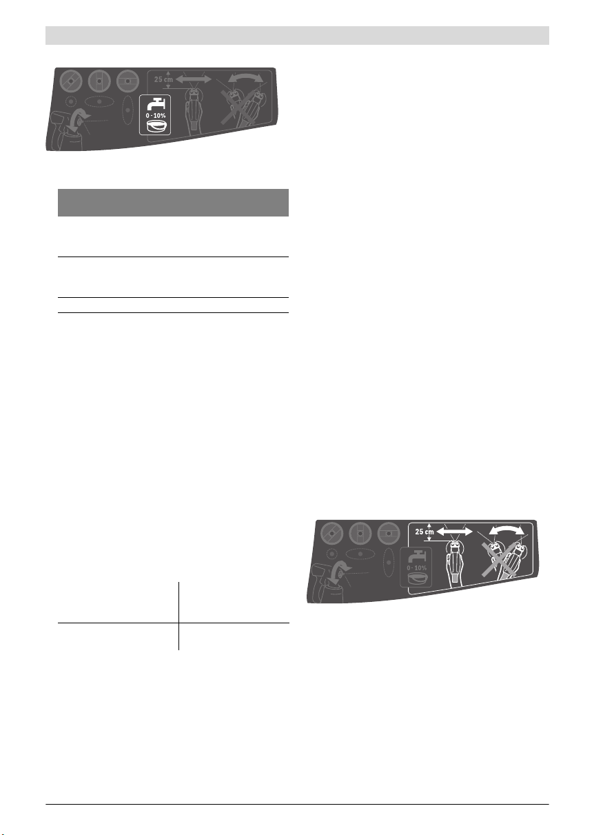
Préparation du produit de pulvérisation
– Agitez bien le produit de pulvérisation.
– Si nécessaire, diluez le produit de pulvérisation.
Produit de pulvérisation Degré de dilution
Teintes à bois, huiles, lasures,
produits d’imprégnation, apprêts
anti-rouille
Vernis diluables ou à base de
solvants, apprêts, vernis pour
radiateur, lasures épaisses
Peintures acryliques, peintures latex au moins 10 %
Lors du processus de dilution, veillez à ce que le produit
de pulvérisation et le diluant correspondent. L’utilisa-
tion d’un diluant non approprié provoque la formation de
grumeaux bouchant le pistolet-pulvérisateur.
En cas de dilution du produit de pulvérisation, veillez à
ce qu’après la dilution le point d’éclair du mélange se situe toujours au-dessus de 55 °C. La dilution de certains
produits, notamment les vernis à base de solvants, a pour
effet d’abaisser leur point d’éclair.
Remplir le produit de pulvérisation (voir figures D1 – D2)
Note : Avant de verser le produit de pulvérisation, retirez le
flexible d’air 17 en tournant la fermeture baïonnette 18 d’un
quart de tour dans le sens inverse des aiguilles d’une montre
et en dégageant ensuite la fermeture baïonnette 18 du raccord 4.
– Dévissez le récipient 7 du pistolet-pulvérisateur.
– Versez le produit de pulvérisation au maximum jusqu’à la
marque 800 du godet 7.
– Tournez le tuyau de montée 12 de sorte que le produit de
pulvérisation puisse être pulvérisé presque sans résidus :
pour les travaux de pulvérisation auprès d’objets disposés
à plat
pour les travaux de pulvérisation au-dessus de la tête
– Effectuez une pulvérisation d’essai sur une surface-té-
moin. (voir « Pulvérisation », page 27)
Si vous obtenez une diffusion optimale, vous pouvez commencer à pulvériser.
ou
Si le résultat n’est pas satisfaisant ou que la peinture ne sort
pas, procédez conformément à la description « Guide de
dépannage » à la page 29.
recommandé
0%
10 %
vers l’avant da ns la b us e e t
le clapet à air
vers l’arrière dans le sens
de la poignée
Français | 27
Mise en service (voir figure E)
Tenez compte de la tension du réseau ! La tension de la
source de courant doit correspondre aux indications se
trouvant sur la plaque signalétique de l’outil électroportatif.
Veillez à ce que l’unité de b ase ne puisse pas aspirer de
la poussière ou d’autres encrassements pendant la
mise en service.
Veillez à ne jamais pulvériser l’unité de base.
Dès que du produit s’échappe par un autre endroit que
par la buse, interrompez la pulvérisation et rétablissez
le fonctionnement normal du pistolet-pulvérisateur en
vérifiant son montage. Il y a risque de choc électrique.
Ne pas pulvériser en direction de soi-même ou d’autres
personnes ou des animaux.
Mise en marche
Pour économiser l’énergie, ne mettez en marche le système
de pulvérisation fine qu’au moment de son utilisation.
– PFS 2000: Vérifiez si la bonne buse est en place (voir
« Remplacement de la buse », page 26).
– Branchez la fiche dans la prise.
– P re ne z le pi st ol et- pu lv ér isa te ur en mai n e t d ir ige z- le ve rs l a
surface à pulvériser.
– Poussez vers l’avant l’interrupteur marche-arrêt 20.
–Appuyez sur l’interrupteur 6 du pistolet-pulvérisateur.
Note : Lorsque l’unité de base est mise en marche, de l’air sort
toujours du capuchon d’air 2.
Arrêt
– Relâchez la commande 6 et poussez l’interrupteur marche-
arrêt 20 vers l’arrière.
– Retirez la fiche de la prise de courant.
Instructions d’utilisation
Pulvérisation (voir figure F)
Note : Tenez compte de la direction du vent si vous utilisez
l’outil électroportatif à l’extérieur.
– Effectuez d’abord une pulvérisation d’essai et réglez la dif-
fusion et la quantité du produit de pulvérisation conformé-
ment au produit de pulvérisation. (pour les réglages, voir
les chapitres suivants)
– Tenez impérativement le pistolet-pulvérisateur à la verti-
cale, toujours à la même distance (20 –25 cm) de la sur-
face à pulvériser.
– Commencez le processus de pulvérisation à l’extérieur de
la surface à pulvériser.
Bosch Power Tools 2 609 007 770 | (16.9.14)
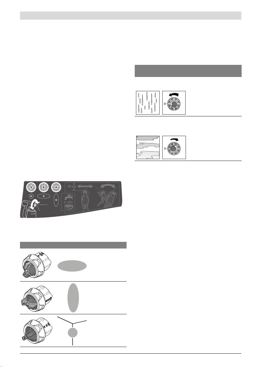
28 | Français
– En fonction du réglage de la diffusion, faites passer le pis-
tolet-pulvérisateur régulièrement de la gauche vers la
droite ou du haut vers le bas.
On obtient une surface régulière si les bandes se chevauchent de 4–5cm.
– Lors de travaux de pulvérisation en hauteur ou sur des ob-
jets posés à plat, penchez légèrement le pistolet-pulvérisateur et déplacez-vous vers l’arrière en vous éloignant de la
surface de pulvérisation.
Risque de trébuchement ! Prendre garde aux obstacles
qui se trouvent dans la pièce.
– Evitez les interruptions sur la surface à pulvériser.
Un guidage régulier du pistolet-pulvérisateur résulte en une
qualité de surface uniforme.
Une distance et un angle de pulvérisation irréguliers en-
traînent une formation élevée de brouillards de peinture et
ainsi une surface non uniforme.
– Terminez le processus de pulvérisation en dehors de la sur-
face à pulvériser.
Ne videz jamais complètement le récipient (godet) contenant
le produit de pulvérisation. Quand l’extrémité du tube d’immersion ne plonge plus complètement dans le produit de pulvérisation, le brouillard de peinture devient discontinu et on
obtient une surface non uniforme.
Si le produit à pulvériser s’ac cumule sur la buse et sur le clapet
à air, nettoyez les deux pièces avec le diluant utilisé.
Réglage de la diffusion
N’actionnez jamais l’interrupteur 6 pendant que vous
réglez le clapet à air 2.
– Tournez le clapet à air 2 dans la position souhaitée.
Clapet à air Jet Utilisation
jet plat horizontal
pour sens de travail
vertical
jet plat vertical pour
sens de travail horizontal
jet rond pour
angles, bords et endroits d’accès difficile
Réglage de la quantité du produit de pulvérisation
(voir figure G)
(PAINTVolume)
– Tournez la molette de réglage 5 pour régler la quantité de
produit de pulvérisation souhaitée :
– : quantité minimale du produit de pulvérisation,
+ : quantité maximale du produit de pulvérisation.
Quantité du produit de
pulvérisation
Trop de produit de pulvérisation sur la surface à pulvériser :
Pas assez de produit de pulvérisation sur la surface à
pulvériser :
Réglage
Il faut réduire la quantité de
produit de pulvérisation.
– Tournez la molette 5 dans
le sens –.
Il faut augmenter la quantité
de produit de pulvérisation.
– Tournez la molette 5 dans
le sens +.
Pauses de travail et transport (voir figures H –I)
Pour un transport facile du système de pulvérisation fine,
l’unité de base possède une poignée 21 et une sangle 22.
Pendant l’utilisation, l’unité de base 19 peut être portée en
bandoulière sur l’épaule à l’aide de la sangle 22.
Pendant les pauses, le pistolet-pulvérisateur 1 peut être posé
sur une surface plane, sans que du produit de pulvérisation ne
risque de couler.
Tant qu’il y a du produit de pulvérisation dans le godet,
toujours poser le pistolet-pulvérisateur debout sur une
surface plane. Si le pistolet-pulvérisation est posé à plat
ou en position penchée, du produit risque de couler.
Entretien et Service Après-Vente
Nettoyage et entretien
Avant d’effectuer des travaux sur l’outil électroporta-
tif, retirez la fiche de la prise de courant.
Nettoyez soigneusement après chaque utilisation les
différentes parties du pistolet-pulvérisateur, notam-
ment les pièces en contact avec la peinture. Un net-
toyage correct est primordial pour un fonctionnement cor-
rect et en toute sécurité du pistolet-pulvérisateur. Tout
recours en garantie est exclu si l’appareil est mal entretenu
ou mal nettoyé.
Dans le cas où un remplacement de la fiche de raccordement
s’avère nécessaire, ceci ne doit être effectué que par Bosch
ou une station de Service Après-Vente agréée pour outillage
Bosch afin d’éviter des dangers de sécurité.
2 609 007 770 | (16.9.14) Bosch Power Tools

Nettoyage du filtre à air (voir figure J)
Le filtre à air 26 a besoin d’être nettoyé occasionnellement. Si
le filtre à air est fortement encrassé, le remplacer.
– Ouvrez le couvercle du filtre à air 23.
– Retirez le filtre à air 26.
– S’il est faiblement encrassé :
Nettoyez le filtre à air 26 en le tapotant.
ou
S’il est fortement encrassé :
Nettoyez le filtre à air 26 à l’eau courante et laissez-le ensuite sécher complètement, afin d’éviter la formation de
moisissures.
ou
Remplacez le filtre à air 26.
– Remontez le filtre à air.
– Refermez le couvercle du filtre à air 23.
Nettoyer le système de pulvérisation fine (voir figure K)
Nettoyez toujours le pistolet-pulvérisate ur et le récipient du
produit de pulvérisation avec le diluant correspondant (solvant ou eau) pour le produit de pulvérisation utilisé.
Ne jamais nettoyer les orifices d’air et de buse du pistolet-pulvérisateur à l’aide d’un objet pointu.
– Éteignez l’unité de base 19.
– Débranchez le tuyau flexible 17 aussi bien au niveau de
l’unité de base 19 qu’au niveau du pistolet-pulvérisateur 1
en tournant la fermeture baïonnette 18 d’un quart de tour
dans le sens inverse des aiguilles d’une montre et en dégageant ensuite la fermeture baïonnette 18 du raccord 4/24.
– Nettoyez si nécessaire l’unité de base avec un chiffon en-
duit de diluant et éloignez ensuite l’unité de base 19 et le
tuyau flexible 17 de la zone de nettoyage immédiate.
– Actionnez l’interrupteur 6 du pistolet-pulvérisateur, afin
de permettre au produit de pulvérisation de regagner le godet.
– Dévissez le récipient (godet) 7 et videz son contenu dans
le pot contenant le produit de pulvérisation d’origine.
– Remplissez le récipient (godet) 7 à moitié de diluant (sol-
vant ou eau) et fixez-le à nouveau sur le pistolet-pulvérisateur 1.
– Secouez plusieurs fois le pistolet-pulvérisateur.
Français | 29
– Dévissez le godet 7 et videz-le complètement dans un pot
vide.
– Retirez l’écrou-raccord 3, le clapet à air 2, la rondelle
étanche 11
le tube d’immersion 12 avec l’opercule du récipient 14.
Assurez-vous que le joint torique 10 reste sur la buse.
– Nettoyez dans un seau rempli de diluant toutes les pièces
qui entrent en contact avec la peinture, à l’aide d’une
brosse à vaisselle ordinaire.
Nettoyez aussi le canal de peinture 16 du pistolet-pulvéri-
sateur 1.
– Contrôlez si le tube d’immersion 12 avec l’opercule du ré-
cipient 14 sont exempts de produit de pulvérisation et
sans dommages.
En cas de besoin, nettoyez à nouveau l’opercule du réci-
pient 14 avec du diluant.
Nettoyez l’orifice de ventilation 15 avec un objet adapté.
– Nettoyez l’extérieur du récipient et du pistolet-pulvérisa-
teur au moyen d’un chiffon humidifié avec du diluant.
– Laissez soigneusement sécher tous les éléments avant de
les assembler.
– Réassemblez le système de pulvérisation fine en procé-
dant dans l’ordre inverse.
Assurez-vous de bien repousser le tube d’immersion 12
jusqu’à la butée sur le conduit de peinture 16 et l’opercule
du récipient 14 dans la gorge du tube d’immersion 12.
Elimination du produit
Les diluants et restes du produit de pulvérisation doivent être
éliminés en respectant les directives relatives à la protection
de l’environnement. Respectez les consignes d’élimination indiquées par le fabricant et les prescriptions locales concernant l’élimination de déchets spéciaux.
Les produits chimiques polluant ne doivent pas pénétrer dans
la terre, les nappes phréatiques ou les cours d’eau. Ne jetez jamais des produits chimiques polluants dans les
canalisations !
Stockage
– Avant de ranger le système de pulvérisation fine, nettoyez-
le soigneusement et faites bien sécher toutes les pièces
avant le remontage.
, la buse utilisée 9/8, avec le joint torique 10, et
Guide de dépannage
Problème Cause Remède
Le produit de pulvérisation ne
recouvre pas correctement
Bosch Power Tools 2 609 007 770 | (16.9.14)
La quantité de produit de pulvérisation est
trop basse
La distance vers la surface à pulvériser est
trop grande
Pas assez de produit de pulvérisation sur la
surface à pulvériser, la surface n’a pas été
pulvérisée assez souvent
Le produit de pulvérisation est trop visqueux Diluer à nouveau le produit de pulvérisation
Tourner la molette 5 dans le sens +
Réduire la distance
Pulvériser plus souvent la surface
et effectuer une pulvérisation d’essai
 Loading...