How it Works
Log In / Sign Up
Buy Points
How it Works
FAQ
Contact Us
Questions and Suggestions
Users
Bosch
Loading...
P
P675L24E
P775N14E
P875L24E
2
P875N14E
2
P975N14E
2
PAD 12001
PAD16001
PAD 20001
2
PAG 14,4V
PAG675T03E
5
PAM 0320
PAM0520
PAM0530
PAM0540
PAM 220
5
PAM-4
PAN 67..
PAN675T01
8
Panel Controller
3
PAS 11-21
10
PAS 12-27
6
PAS 12-27 F
6
PAS 18 LI
4
PAS 21-27F
PB10
2
PB10-CD
2
pb180
pb360c
pb360c-c
PB360D
PB360D-C
PB360S
PB360S-C
PBA 18V 2,5 Ah W-B
PBC-60
2
PBC6B
PBD 40
9
PBH160RE
PBH1800RE
PBH180RE
2
PBH 2000 RE
6
PBH 2000 SRE
4
PBH200FRE
2
PBH200RE
2
PBH 2100
PBH 2100 RE
17
PBH 2100 RE (0.603.3A9.303)
PBH 2100 SRE
15
PBH 2100 SRE 06033A9321
PBH 220 RE
3
PBH 240 RE
2
PBH 2500 RE
13
PBH 2500 RE 0603344421
PBH 2500 RE Professional
PBH 2500 SRE
10
PBH 2800 RE
10
PBH 2800 RE Professional
PBH 2900 FRE
8
PBH 2900 RE
4
PBH 2900 RE Professional
PBH 3000-2 FRE
11
PBH 3000 FRE
8
PBH 3000 FRE Professional
PBH 3000 FRE Set
6
PBH 300 E
3
PBH6
PBH615B80A
3
PBH615B80E
9
PBH615B80L
3
PBH615B90E
8
PBH615B9TA
2
PBH6B
PBH6B5B 60
5
PBH6B5B60A
2
PBH6B5B60N
PBH 6B5 B 80
PBH6B5B80A
2
PBH6B5B90A
2
PBH6C2B90R
3
PBH6C5B60O
PBH6C5B62O
PBH6C5B90R
PBH6C5B92R
PBH6C5B95R
3
PBH6C6B90R
2
PBK
PBP0C5Y80N
PBP6
PBP612B80E
8
PBP613B80E
10
PBP613B90E
6
PBP615B80E
10
PBP615B80L
2
PBP615B81E
10
PBP615B90E
8
PBP616B80E
5
PBP616B90E
3
PBP616B90R
2
PBP6B
PBP 6B3 B 80
Loading...
Loading...
Nothing found
PBH 2800 RE
Original Instruction
159 pgs
8.42 Mb
0
Original Instructions Manual
13 pgs
3.49 Mb
0
User Guide
103 pgs
7.01 Mb
0
User guide [ml]
119 pgs
7.16 Mb
0
User Manual
159 pgs
8.26 Mb
0
User Manual
125 pgs
3.83 Mb
0
User Manual
16 pgs
1.06 Mb
0
User Manual [pt]
112 pgs
6.62 Mb
0
User Manual [ru]
173 pgs
8.51 Mb
0
User Manual [ru]
114 pgs
6.6 Mb
0
Table of contents
Loading...
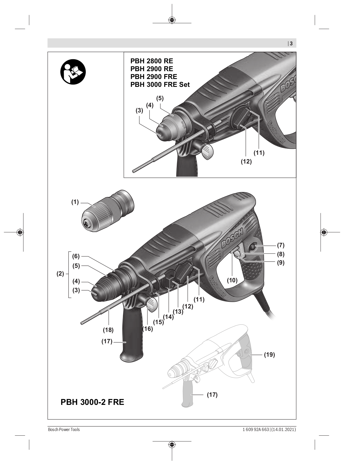
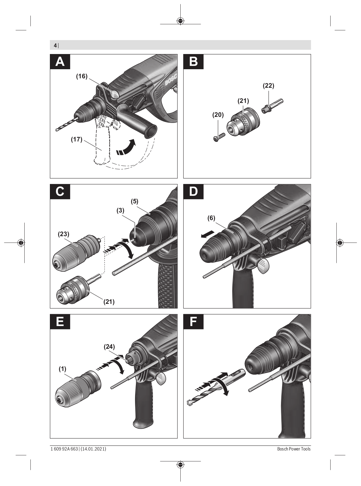
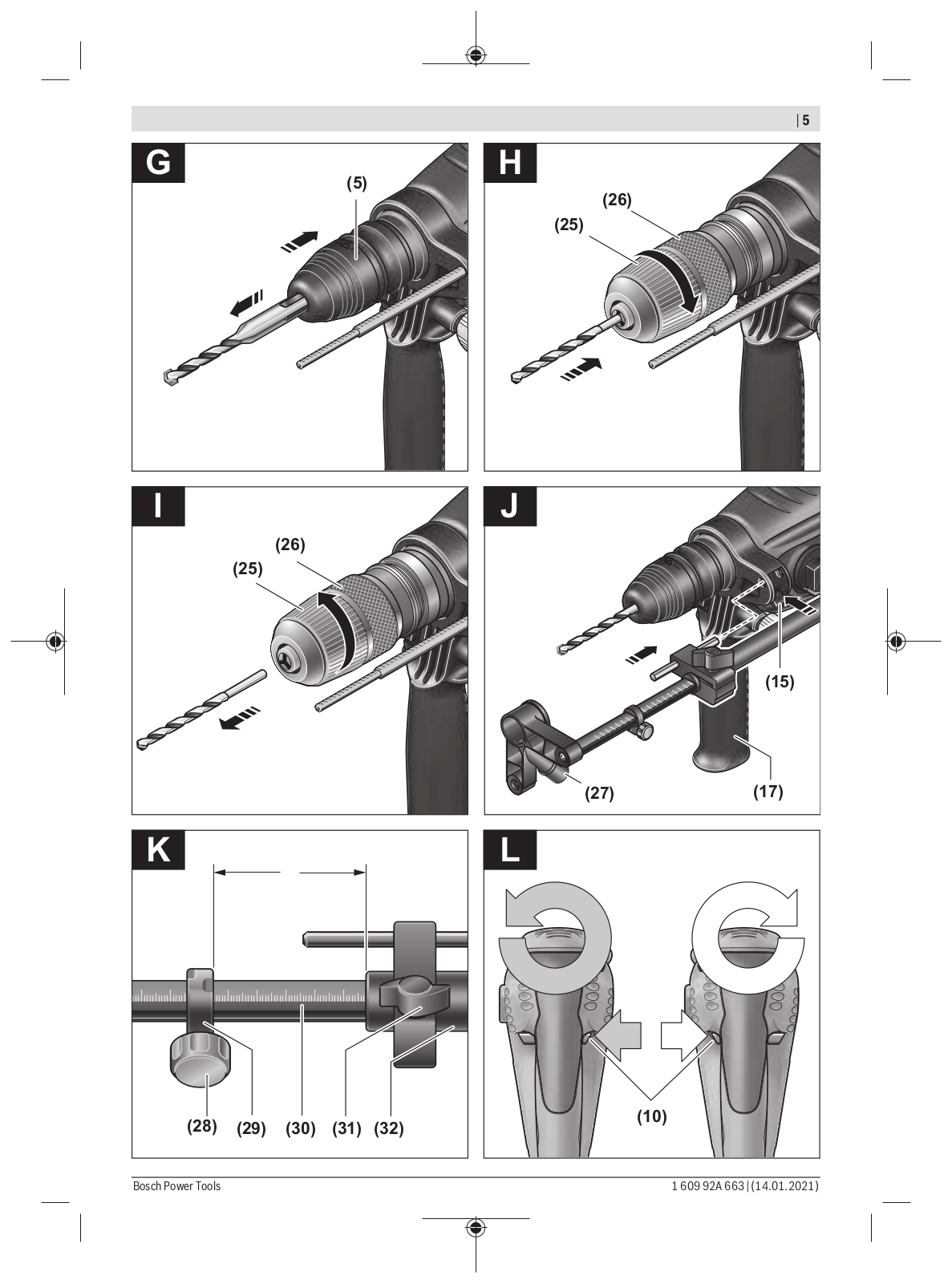
Bosch PBH 2800 RE, PBH 2900 RE, PBH 2900 FRE, PBH 3000 FRE Set User Manual
...
Bosch User Manual
Download
Specifications and Main Features
Frequently Asked Questions
User Manual
Download
Loading...
+
hidden pages
Unhide
You need points to download manuals.
1 point = 1 manual.
You can buy points or you can get point for every manual you upload.
Buy points
Upload your manuals
 Loading...