

Bosch FM441/CMM 910, FM442/CMM 920, FM443/CMS 910, FM444/CMG 910, FM448/CMB 900-0-10V Mounting Instructions
...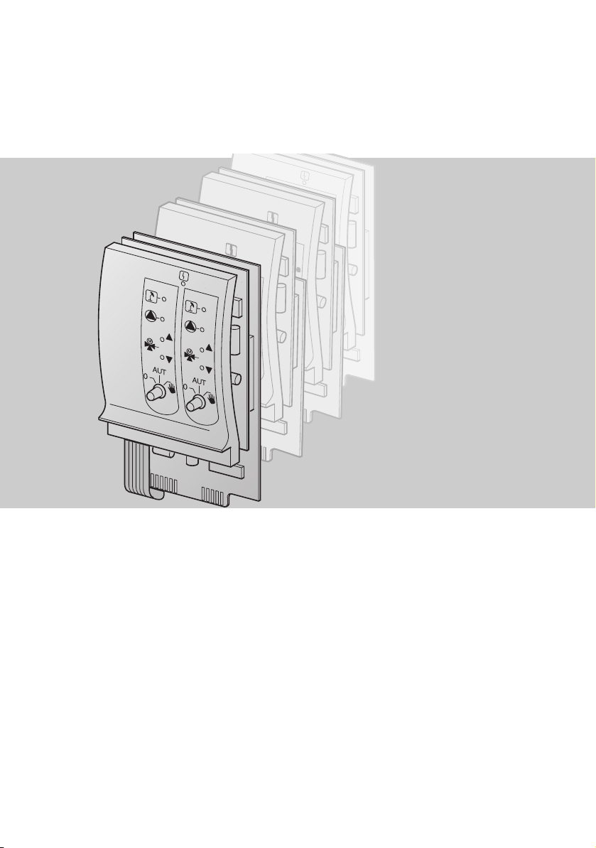
Mounting Instructions
Modules for control units
CSM 7x0, CFB 8x0 and CFB 9x0
FM441/CMM 910 FM455/CMC 900
FM442/CMM 920 FM457/CMC 920
FM443/CMS 910 FM458/CMC 930
FM444/CMG 910
FM448/CMB 900-0-10V
6 720 803 029 (2011/08) GB/IE/AU

2 |
1 Introduction. . . . . . . . . . . . . . . . . . . . . . . . . . . . . . . . . . . 3
1.1 Definition of the various modules . . . . . . . . . . . . . . . . . . . 3
1.2 Modules and their designation. . . . . . . . . . . . . . . . . . . . . 4
2 Safety . . . . . . . . . . . . . . . . . . . . . . . . . . . . . . . . . . . . . . . 5
2.1 About these instructions . . . . . . . . . . . . . . . . . . . . . . . . 5
2.2 Determined use . . . . . . . . . . . . . . . . . . . . . . . . . . . . . . 5
2.3 Standards and directives . . . . . . . . . . . . . . . . . . . . . . . . 5
2.4 Explanation of the symbols used . . . . . . . . . . . . . . . . . . . 6
2.5 Observe this information . . . . . . . . . . . . . . . . . . . . . . . . 6
2.6 Disposal . . . . . . . . . . . . . . . . . . . . . . . . . . . . . . . . . . . 7
3 Module assembly for control units CSM 7x0 . . . . . . . . . . 8
3.1 Possible module installations for control units CSM 7x0 . . . . 8
3.2 Arrangement of the modules in the control unit (CSM 7x0) . . 9
3.3 Fitting . . . . . . . . . . . . . . . . . . . . . . . . . . . . . . . . . . . .10
3.4 Removing and replacing the function module
FM455/CMC 900 (only for CSM 750)
. . . . . . . . . . . . . . . . .19
4 Module mounting for control unit CFB 840 . . . . . . . . . . .21
4.1 Possible module installations for control unit CFB 840 . . . . . 21
4.2 Arrangement of modules in the control unit . . . . . . . . . . . .22
4.3 Fitting . . . . . . . . . . . . . . . . . . . . . . . . . . . . . . . . . . . .23
5 Module assembly for control units CFB 9x0 . . . . . . . . . . 27
5.1 Possible module installations for control units CFB 9x0 . . . .27
5.2 Arrangement of modules in the control unit . . . . . . . . . . . .28
5.3 Fitting . . . . . . . . . . . . . . . . . . . . . . . . . . . . . . . . . . . .30
6 720 803 029 (2011/08) Modules for control units CSM 7x0, CFB 8x0 and CFB 9x0
1 Introduction
These mounting instructions explain installation of the function modules
CMx in the control unit series CSM 7x0, CFB 8x0 and CFB 9x0.
USER INFORMATION
Generally, these installation instructions c an a lso be used fo r in sta lling
other modules, as the procedure is similar.
1.1 Definition of the various modules
Definitions
CM = Controller module
CMx = Function module
NM = Power supply module
ZM = Central or auxiliary module
Tab. 1 Definition of modules
Introduction | 3
6 720 803 029 (2011/08)Modules for control units CSM 7x0, CFB 8x0 and CFB 9x0

4 | Introduction
1.2 Modules and their designation
Controller
module
Power
supply
module
Central
module
Function
module
Auxiliary
module
Tab. 2 Module designations
Designation Name
CM431 Controller module
NM482 Power supply module
ZM422
ZM424
ZM432 Burner + boiler circuit functions
ZM433
ZM434
ZM425 Display module
FM441/CMM 910 1 heating circuit + 1 DHW circuit
FM442/CMM 920 2 heating circuits
FM443/CMS 910 Solar circuit
FM444/CMG 910 Alternative heat generator
FM448/CMB 900-0-10V Central fault message
FM455/CMC 900
FM456/CMC 910
FM457/CMC 920
FM458/CMC 930 Strategy + EMS
ZM427/CME 930 Boiler operating module
Burner control + 1 heating circuit
+ 1 DHW circuit
Boiler control + 2 heating circuits
+ 1 DHW circuit
External heat generation +
1 heating circuit
Burner + boiler circuit functions +
0 - 10 % burner control
KSE 1 (only with ZM424)
with EMS
KSE 2 (cascade –
2 wall mounted boilers) with EMS
KSE 4 (cascade –
4 wall mounted boilers) with EMS
6 720 803 029 (2011/08) Modules for control units CSM 7x0, CFB 8x0 and CFB 9x0
2Safety
2.1 About these instructions
This chapter contains general safety instructions which must be observed
when installing the function modules CMx in the control units CSM 7x0,
CFB 8x0 and CFB 9x.
Also closely observe further safety instructions in other chapters of these
installation instructions. Please read the safety instructions carefully before
starting the installation.
If safety instructions are ignored, severe or even fatal injuries may result,
as well as material losses and environmental damage.
2.2 Determined use
You can integrate the function modules CMx into the control units
CSM 7x0, CFB 8x0 and CFB 9x0.
2.3 Standards and directives
Safety | 5
The design and operation of this product conforms to the
European Directives and the supplementary national
requirements. Its conformity is confirmed by the CE
designation.
You may request the declaration of conformity for the
product. See rear page for contact details of your local
branch or from the relevant Bosch Thermotechnology
branch.
6 720 803 029 (2011/08)Modules for control units CSM 7x0, CFB 8x0 and CFB 9x0
6 | Safety
2.4 Explanation of the symbols used
Two levels of danger are identified and signalled by the following terms:
RISK OF FATAL INJURY
Identifies possible risks associated with a product that might lead to
serious injury or even death if appropriate care is not taken.
WARNING!
RISK OF INJURY / SYSTEM DAMAGE
Identifies potentially dangerous situations, which might lead to
medium or slight injuries or to material damage
CAUTION!
USER INFORMATION
User tips for the optimum utilisation and adjustment of the appliance
plus other useful information.
2.5 Observe this information
The function modules CMx were designed and built according to the state
of the art and the recognised safety-related standards.
However, material losses resulting from incorrect installation cannot be
completely excluded.
Before installing the CM function modules, read these mounting
instructions carefully.
RISK TO LIFE
from electricity.
z The installation, electrical wiring, commissioning, electrical
WARNING!
connection, as well as maintenance and repairs must only be
carried out by a competent contractor who adheres to all current
technical regulations and requirements.
z Regional regulations should be observed in this regard!
6 720 803 029 (2011/08) Modules for control units CSM 7x0, CFB 8x0 and CFB 9x0
Observe the following safety instructions during the installation of the
function modules.
RISK TO LIFE
from electricity.
z Ensure that all electrical work is only carried out by an authorised
WARNING!
electrician.
z Before opening the control unit: Isolate all poles of the power
supply and secure against unintentional reconnection.
RISK TO LIFE
from electricity.
WARNING!
The risk of voltage flashes through unintentional loosening of the cores
at the terminals between the 230 V and the LV
1)
must be prevented.
z Therefore fix the wires from each cable away from each other
(e.g. with cable ties) or only strip the wire for a very short section.
1)
LV-terminal - extra low voltage connection for sensors, volt free connections and BUS.
DAMAGE TO THE APPLIANCE
through electrostatic discharge (ESD).
CAUTION!
z Before unpacking the modules touch a radiator or a earthed metal
water pipe to discharge any electrostatic charge in your body.
Safety | 7
2.6 Disposal
USER INFORMATION
Ensure that a regulation isolator is available to disconnect all poles
from the mains power supply. Install an isolator if none is available.
USER INFORMATION
Only use original replacement parts from Bosch Thermotechnology.
Bosch Thermotechnology cannot take responsibility for losses caused
by the use of parts not supplied by Bosch Thermotechniology.
z Electronic components must not be disposed of with general domestic
waste.
Dispose of old modules correctly through an authorised disposal site.
6 720 803 029 (2011/08)Modules for control units CSM 7x0, CFB 8x0 and CFB 9x0
8 | Module assembly for control units CSM 7x0
3 Module assembly for control units CSM 7x0
This section describes the installation of the function modules CMx in
the control units CSM 710 and CSM 750.
USER INFORMATION
z Check that all parts have been delivered.
If this is not the case, contact a Bosch Thermotechnology branch.
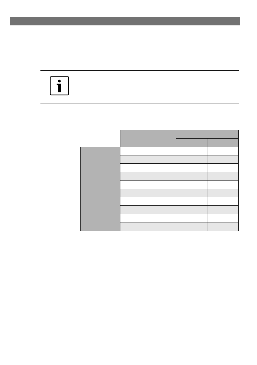
3.1 Possible module installations for control units CSM 7x0
Designation
CM431 O O
NM482 O O
ZM424 O –
FM441/CMM 910 – X
Modules
Tab. 3 Standard equipment of control units and extension options
O = Standard equipment
X = Accessories
– = Combination/installation not possible
FM442/CMM 920 X X
FM443/CMS 910 X X
FM444/CMG 910 X X
FM448/CMB 900-0-10V X X
FM455/CMC 900 O –
FM457/CMC 920 X X
CMS 7x0
CSM 750 CSM 710
6 720 803 029 (2011/08) Modules for control units CSM 7x0, CFB 8x0 and CFB 9x0

Module assembly for control units CSM 7x0 | 9
1
3
4
2
3.2 Arrangement of the modules in the control unit (CSM 7x0)
Fig 1 Slot assignment
1 Slot 1
2 Slot 2
3 Slot B behind the programming unit
4 Slot A for function module FM455/CMC 900 (only for CSM 750)
ZM424 and FM455/CMC 900 (only for CSM 750)
The module FM455/CMC 900 always occupies slot A (Æ Fig. 1, [4]) and the
module ZM424 slot 1 (Æ Fig. 1, [1]).
FM457/CMC 920
Control units which contain the function module FM457/CMC 920 should
be set as master. (Set as 0 if only one CSM 7x0 used, set as 1 if more than
1 CSM 7x0 used). Make this setting at the CM431 controller module.
6 720 803 029 (2011/08)Modules for control units CSM 7x0, CFB 8x0 and CFB 9x0
10 | Module assembly for control units CSM 7x0
2
1
3
4
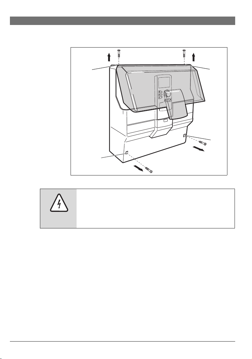
3.3 Fitting
Fig 2 Removing covers
RISK OF FATAL INJURY
due to electrical current when the control unit is open.
WARNING!
z Before opening the control unit:
Isolate all poles of the power supply and secure against
unintentional reconnection.
z Unscrew 2 screws on the upper housing cover (Æ Fig. 2, [1] and [2]).
z Remove top casing cover.
z Unscrew 2 screws on the cable cover (Æ Fig. 2, [3] and [4]).
z Remove cable cover.
6 720 803 029 (2011/08) Modules for control units CSM 7x0, CFB 8x0 and CFB 9x0
Module assembly for control units CSM 7x0 | 11
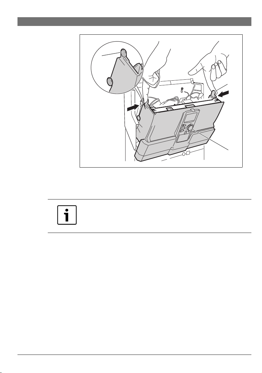
1
2
3
Fig 3 Pivoting down device front
z Press in upper nubs (Æ Fig. 3, [1] and [2]) on both sides.
z Fold out forwards the device front with the Programmer (Æ Fig. 3, [3]).
USER INFORMATION
Ensure that the cable cover has been removed, otherwise you will not
be able to pivot the device front forward.
6 720 803 029 (2011/08)Modules for control units CSM 7x0, CFB 8x0 and CFB 9x0

12 | Module assembly for control units CSM 7x0
1
2
3
Fig 4 Removing the cross brace
You will need a screwdriver to remove the crossbar (Æ Fig. 4, [1]).
z Undo the crossbar on one side. For this push one of the two clips
(Æ Fig. 4, [3]) outwards with the screwdriver.
z Lift the crossbar on one tab (Æ Fig. 4, [2]).
z Push the second clip outwards with the screwdriver.
z Lift crossbar at the second tab.
z Lift crossbar on this side off its retainer.
z Also undo crossbar on the other side.
z Remove crossbar (Æ Fig. 4, [1]).
6 720 803 029 (2011/08) Modules for control units CSM 7x0, CFB 8x0 and CFB 9x0

Module assembly for control units CSM 7x0 | 13
Fig 5 Removing blanking plate
When fitting a new module
z Remove blanking plate from slot 1 (Æ Fig. 5) in the control unit.
z Connection cables for sensors and pumps must be laid and provided
with terminals before installation of the module (more detailed
information can be found in the technical documentation for control
units CSM 7x0).
WARNING!
RISK TO LIFE
through metal jumpers.
z When stripping insulation or cutting cables, ensure that pieces of
cable do not fall into the electrical or electronic system.
z Push new module from above into the free slot by pressing on the
sensor strip (Æ Fig. 6, page 14) until it clicks audibly into place.
6 720 803 029 (2011/08)Modules for control units CSM 7x0, CFB 8x0 and CFB 9x0

14 | Module assembly for control units CSM 7x0
Fig 6 Inserting a module
When removing and replacing a module
z Disconnect leads for the respective module and fix in standby position
(more detailed information can be found in the mounting instructions
for control units CSM 7x0).
z Pull module out of the control unit.
z Push new module from above into the free slot by pressing on the
sensor strip (Æ Fig. 6) until it clicks audibly into place.
6 720 803 029 (2011/08) Modules for control units CSM 7x0, CFB 8x0 and CFB 9x0

Module assembly for control units CSM 7x0 | 15
Netz
L
N
Fig 7 Connect power supply to slot 1
Connecting module power supply to slot 1
z Plug in sensor leads and pump connections at the designated points on
the module.
z Plug 230 V module connector into the correct position in the terminal
strip (Æ Fig. 7).
6 720 803 029 (2011/08)Modules for control units CSM 7x0, CFB 8x0 and CFB 9x0

16 | Module assembly for control units CSM 7x0
Fig 8 Connecting power to slot 2
Connecting module power supply to slot 2
z Remove dummy plug (Æ Fig. 8, [1]) of the three-pole plug (cable loom).
z Plug in 230 V module connecting plug to the three-pole plug
(Æ Fig. 8, [2]).
6 720 803 029 (2011/08) Modules for control units CSM 7x0, CFB 8x0 and CFB 9x0

Module assembly for control units CSM 7x0 | 17
1
2
Fig 9 Positioning crossbar
After module installation
z Position crossbar (Æ Fig. 9, [1]) in the recesses and click into place.
z Pivot the device front (Æ Fig. 9, [2]) back and click into place.
6 720 803 029 (2011/08)Modules for control units CSM 7x0, CFB 8x0 and CFB 9x0

18 | Module assembly for control units CSM 7x0
2
1
3
4
Fig 10 Fitting casing cover and cable cover
z Position top casing cover.
z Replace both screws on the upper housing cover (Æ Fig. 10, [1]
and [2]).
z If additional cables were routed out of the device, the cable cover
may need to be cut out in the lower section.
z Position cable cover.
z Replace both cable cover screws (Æ Fig. 10, [3] and [4]).
z Test the module function.
More detailed information can be found in the operating and servicing
instructions for control units CSM 7x0.
6 720 803 029 (2011/08) Modules for control units CSM 7x0, CFB 8x0 and CFB 9x0

Module assembly for control units CSM 7x0 | 19
3.4 Removing and replacing the function module FM455/CMC 900 (only for CSM 750)
Fig 11 Replacing the module FM455/ CMC 900
If it is necessary to replace the FM455/CMC 900 module, first remove the
ZM424 module from slot 1.
z Remove 230 V module connecting plug (Æ Fig. 7, page 15) and all the
connecting cables of the module ZM424 and fix in standby position.
z Pull out the ZM424 module.
z Pull out the PCB below – the FM455/CMC 900 module (Æ Fig. 11).
z Insert new FM455/CMC 900 module.
z Reinsert the ZM424 module by pressing on the sensor strip.
z Reconnect all connecting cables in their original positions.
z Reconnect the 230 V module power supply of the ZM424.
6 720 803 029 (2011/08)Modules for control units CSM 7x0, CFB 8x0 and CFB 9x0

20 | Module assembly for control units CSM 7x0
Jumper switch
The jumper switch is used to configure the module:
Position
open
(factory
setting)
USER INFORMATION
The jumper switch must be open if EMS is in use.
Function
The module logs on as a new
module FM455/CMC 900 or
FM457/CMC 920.
Fig 12 Jumper switch (e.g. FM457/CMC 920)
USER INFORMATION
If there is no 230 V power supply for the module or one of its 230 V
components (e.g. plug-in connection has not been made), the relevant
components (e.g. pumps) will not be activated.
You cannot recognise this error on the module in question since the
LED and the control functions work independently of this power
supply. Check cable connections thoroughly before re-fitting controller
casings.
6 720 803 029 (2011/08) Modules for control units CSM 7x0, CFB 8x0 and CFB 9x0

Module mounting for control unit CFB 840 | 21
4Module mounting for control unit CFB 840
This section describes the installation of the function modules CMx in the
control unit CFB 840.
USER INFORMATION
z Check that all parts have been delivered.
If this is not the case, contact a Bosch Thermotechnology branch.
4.1 Possible module installations for control unit CFB 840
Designation CFB 840
CM431 O
NM482 O
ZM422 O
Modules
Tab. 4 Standard equipment level of the control unit and extension options
O = Standard equipment
X = Accessories
– = Combination/installation not possible
FM442/CMM 920 X
FM443/CMS 910 X
FM444/CMG 910 X
FM448/CMB 900-0-10V X
ZM426 X
USER INFORMATION
Generally, you can freely select the installation position of the modules.
6 720 803 029 (2011/08)Modules for control units CSM 7x0, CFB 8x0 and CFB 9x0

22 | Module mounting for control unit CFB 840
Z
L
1
2
4
3
4.2 Arrangement of modules in the control unit
Fig 13 Slot assignment
1 Slot 1 for an additional module
2 Slot 2 for an additional module
3 Slot B behind the Programmer programming unit
4 Slot A for central module ZM422 (standard version)
USER INFORMATION
Slot A (Æ Fig. 13, [4]) is firmly occupied by the central module ZM422,
6 720 803 029 (2011/08) Modules for control units CSM 7x0, CFB 8x0 and CFB 9x0
and slot B (Æ Fig. 13, [3]) is firmly occupied by the controller module
CM431 and the programming unit.
Generally, you can assign the additional modules to any free slot (1-2).
For this ensure that the power supply leads from module to module.
Insert the modules in order from left to right to ensure the heating circuits
are logically numbered (slot 1-2).

4.3 Fitting
1
1
2
Module mounting for control unit CFB 840 | 23
Fig 14 Removing covers
1 Screws
2 Terminal cover
RISK OF FATAL INJURY
due to electrical current when the control unit is open.
WARNING!
z Before opening the control unit:
Isolate all poles of the power supply and secure against
unintentional reconnection.
z Unscrew both screws on the upper side of the appliance
(Æ Fig. 14, [1]).
z Lift terminal cover (Æ Fig. 14, [2]).
6 720 803 029 (2011/08)Modules for control units CSM 7x0, CFB 8x0 and CFB 9x0

24 | Module mounting for control unit CFB 840
Fig 15 Module installation and removal
When fitting a new module
z Remove blanking plate in control unit.
z Connection cables for sensors or pumps must be routedand provided
with terminals before installation of the module (more detailed
information can be found in the technical documentation for control
units CFB 840).
RISK TO LIFE
through metal jumpers.
z When stripping insulation or cutting cables, ensure that pieces of
WARNING!
cable do not fall into the electrical or electronic system.
z Push new module from above into the free slot by pressing on the
sensor strip (Æ Fig. 15) until it clicks audibly into place.
6 720 803 029 (2011/08) Modules for control units CSM 7x0, CFB 8x0 and CFB 9x0

Module mounting for control unit CFB 840 | 25
When removing and replacing a module
z Disconnect leads for the respective module and fix in standby position
(more detailed information can be found in the mounting instructions
for control units CFB 840).
z Pull module out of the control unit.
z Push new module from above into the free slot by pressing on the
sensor strip (Æ Fig. 15, page 24) until it clicks audibly into place.
Fig 16 Providing the 230 V power supply
z Plug sensor leads or pump connections into the correct positions on
the module.
z Plug the 230 V module connector into the correct position on the
terminal strip (for module connection at slot 2, Æ Fig. 16).
6 720 803 029 (2011/08)Modules for control units CSM 7x0, CFB 8x0 and CFB 9x0

26 | Module mounting for control unit CFB 840
USER INFORMATION
The connector clips are locked to prevent slippage.
z When removing the terminals press the locking tab upwards.
z Position terminal cover and secure with the screws.
z Test the module function.
More detailed information can be found in the operating and servicing
instructions for control unit CFB 840.
USER INFORMATION
If there is no 230 V power supply for the module or one of its 230 V
components (e.g. plug-in connection has not been made), the relevant
components (e.g. pumps) will not be activated.
You cannot recognise this error on the module in question since the
LED and the control functions work independently of this power
supply. Check cable connections thoroughly before re-fitting controller
casings.
6 720 803 029 (2011/08) Modules for control units CSM 7x0, CFB 8x0 and CFB 9x0

Module assembly for control units CFB 9x0 | 27
5 Module assembly for control units CFB 9x0
This section describes as a priority the installation of the function modules
CMx in the control units CFB 9x0.
USER INFORMATION
z Check that all parts have been delivered.
If this is not the case, contact a Bosch Thermotechnology branch.
5.1 Possible module installations for control units CFB 9x0
Designation
CM431 O O
NM482 O O
ZM432 – –
ZM433 – –
ZM434 O O
FM441/CMM 910 X X
Modules
Tab. 5 Standard equipment of control units and extension options
O = Standard equipment
X = Accessories
– = Combination/installation not possible
USER INFORMATION
Generally, you can freely select the installation position of the modules.
FM442/CMM 920 X X
FM443/CMS 910 X X
FM444/CMG 910 X X
FM448/CMB 900-0-10V X X
FM455/CMC 900 – –
FM457/CMC 920 – –
FM458/CMC 930 X X
CFB 930 CFB 910
CFB 9x0
6 720 803 029 (2011/08)Modules for control units CSM 7x0, CFB 8x0 and CFB 9x0

28 | Module assembly for control units CFB 9x0
1 2 3 4
6
5
USER INFORMATION
The modules FM448/CMB 900-0-10V and FM458/CMC 930 must never
be inserted in the same control unit.
If you install both modules (FM448/CMB 900-0-10V and FM458/
CMC 930), this leads to an error message on the Programmer display.
USER INFORMATION
The modules FM457/CMC 920 and FM458/CMC 930 must never be
inserted in the same control unit.
If you install both modules (FM457/CMC 920 and FM458/CMC 930),
this leads to an error message on the Programmer display.
5.2 Arrangement of modules in the control unit
Fig 17 Slot assignment
1 Slot 1 for an additional module
6 720 803 029 (2011/08) Modules for control units CSM 7x0, CFB 8x0 and CFB 9x0
2 Slot 2 for an additional module
3 Slot 3 for an additional module
4 Slot 4 for an additional module
5 Slot B behind the Programmer programming unit
6 Slot A for central module ZM432, ZM434 or ZM437
(standard version)

Module assembly for control units CFB 9x0 | 29
USER INFORMATION
Slot A (Æ Fig. 17, [6]) is firmly occupied with one of the central
modules ZM432, ZM433, ZM434 or ZM437, and slot B (Æ Fig. 17, [5])
is firmly occupied with the controller module CM431 and the
programming unit.
Generally, you can assign the additional modules to any free slot (1-4).
Please ensure that the power supply leads connect from one module to the
next module. Insert the modules in order from left to right to ensure the
heating circuits are logically numbered (slot 1-4).
Example (with the help of the CFB 930)
Heating circuit allocation for two heating circuit modules (FM442/
CMM 920) and one heating circuit and DHW module (FM441/CMM 910):
Fig 18 Example of the function module arrangement
Slot 1
FM442/CMM 920
Slot 2
FM442/CMM 920
Slot 3
FM441/CMM 910
Heating circuit 1 Heating circuit 3 Heating circuit 5
Heating circuit 2 Heating circuit 4 DHW circuit
When installing the module FM458/CMC 930, you may need the connecting
cable enclosed with the module in order to supply the adjacent modules of
the FM458/CMC 930 with mains voltage.
6 720 803 029 (2011/08)Modules for control units CSM 7x0, CFB 8x0 and CFB 9x0

30 | Module assembly for control units CFB 9x0
3
1
2
5.3 Fitting
Fig 19 Removing covers
RISK OF FATAL INJURY
due to electrical current when the control unit is open.
WARNING!
z Before opening the control unit:
Isolate all poles of the power supply and secure against
unintentional reconnection.
z Unscrew both screws (Æ Fig. 19, [1] and [3]) on the upper side of the
appliance.
z Lift off terminal cover (Æ Fig. 19, [2]).
6 720 803 029 (2011/08) Modules for control units CSM 7x0, CFB 8x0 and CFB 9x0

Module assembly for control units CFB 9x0 | 31
Fig 20 Module installation and removal
When fitting a new module
z Remove blanking plate from slot 1 (Æ Fig. 20) in the control unit.
z Connection cables for sensors aor pumps must be routed and provided
with terminals before installation of the module (more detailed
information can be found in the technical documentation for control
units CFB 9x0).
WARNING!
RISK TO LIFE
through metal jumpers.
z When stripping insulation or cutting cables, ensure that pieces of
cable do not fall into the electrical or electronic system.
z Push new module from above into the free slot by pressing on the
sensor strip (Æ Fig. 20) until it clicks audibly into place.
6 720 803 029 (2011/08)Modules for control units CSM 7x0, CFB 8x0 and CFB 9x0

32 | Module assembly for control units CFB 9x0
When removing and replacing a module
z Disconnect leads for the respective module and fix in standby position
(more detailed information can be found in the mounting instructions
for control units CFB 9x0).
z Pull module out of the control unit.
z Push new module from above into the free slot by pressing on the
sensor strip (Æ Fig. 20, Page 31), until you hear it click into place.
Fig 21 Providing the 230 V power supply
z Connect sensor leads and pump connections to the correct positions
on the module.
z Plug the 230 V module connector into the correct position on the
terminal strip (for module connection at slot 1, Æ Fig. 21).
USER INFORMATION
The connector clips are locked to prevent slippage.
z When removing the terminals push the locking tab upwards.
6 720 803 029 (2011/08) Modules for control units CSM 7x0, CFB 8x0 and CFB 9x0

Module assembly for control units CFB 9x0 | 33
z Position terminal cover and secure with the screws.
z Test the module function.
More detailed information can be found in the operating and servicing
instructions for control units CFB 9x0.
USER INFORMATION
If there is no 230 V power supply for the module or one of its 230 V
components (e.g. plug-in connection has not be made), the relevant
components (e.g. pumps) will not be activated.
You cannot recognise this error on the module in question since the
LED and the control functions work independently of this power
supply. Check cable connections thoroughly before re-fitting controller
casings.
6 720 803 029 (2011/08)Modules for control units CSM 7x0, CFB 8x0 and CFB 9x0

34 | Module assembly for control units CFB 9x0
Notes
6 720 803 029 (2011/08) Modules for control units CSM 7x0, CFB 8x0 and CFB 9x0

Notes
Module assembly for control units CFB 9x0 | 35
6 720 803 029 (2011/08)Modules for control units CSM 7x0, CFB 8x0 and CFB 9x0

Australia
Robert Bosch (Australia) Pty Ltd
1555 Centre Rd
Clayton, VIC 3168
Phone 1300 30 70 37
Fax 1300 30 70 38
www.bosch.com.au/hotwater
New Zealand
Phone 0800 4 Bosch or 08 543 352
www.bosch.co.nz
C & F Quadrant Ltd.
Unit L40 Cherry Orchard Industrial Estate
Cherry Orchard, Dublin 10
Tel.: 01.6305700
Fax.: 01.6305706 / 01.6305715
www.cfquadrant.ie
E-mail: sales@cfquadrant.ie
United Kingdom
Bosch Thermotechnology
Cotswold Way, Warndon, Worcester WR4 9SW
All Enquiries: 0844 892 3004
www.boschthermotechnology.co.uk
 Loading...