

Bosch ECU MS 25 Sport User Manual
Engine Control Uni MS 25 Sport
Manual
Version 1.0 12/03/2019

Content
ii/40 Engine Control Unit MS 25 Sport Bosch Motorsport
Content
1 Technical data ................................................................................................................................................................. 3
1.1 System Layout........................................................................................................................................................................................................ 3
1.2 Application.............................................................................................................................................................................................................. 4
1.3 Pin Layout................................................................................................................................................................................................................ 5
1.4 Input Channels....................................................................................................................................................................................................... 9
1.5 Output Channels................................................................................................................................................................................................... 9
1.6 Power Supply ......................................................................................................................................................................................................... 9
1.7 Trigger Wheel ........................................................................................................................................................................................................ 10
2 Starting up the ECU ........................................................................................................................................................ 13
2.1 Installation of software tools............................................................................................................................................................................ 13
2.2 Communication PC to device .......................................................................................................................................................................... 13
2.3 MS 25 Sport programming............................................................................................................................................................................... 13
2.4 Initial Data Application....................................................................................................................................................................................... 22
3 Peripherals....................................................................................................................................................................... 33
4 Getting Started................................................................................................................................................................ 36
5 Engine Performance Calibration ................................................................................................................................... 37
6 Bosch Motorsport support ............................................................................................................................................ 38
7 Wiring Harness................................................................................................................................................................ 39
Technical data | 1
Bosch Motorsport Engine Control Unit MS 25 Sport 3/40
1 Technical data
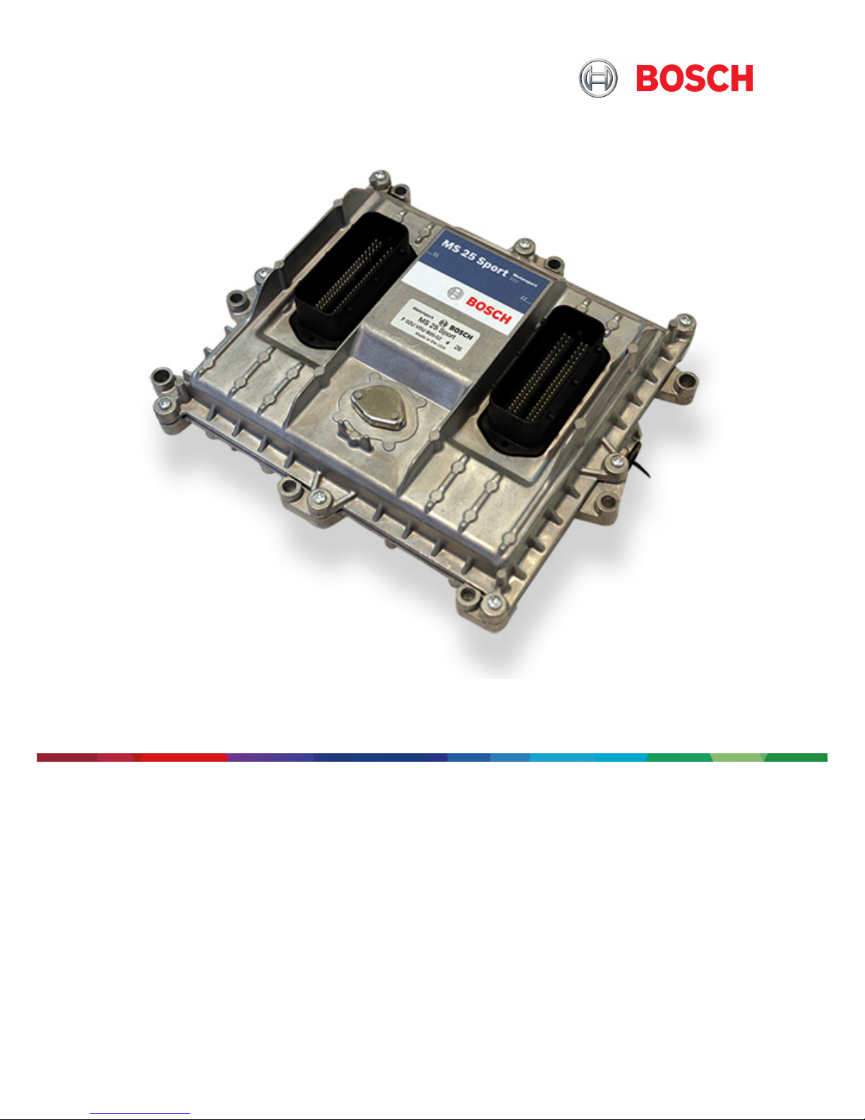
The ECU MS 25 Sport engine control unit manages common rail Diesel engines with
solenoid valve injectors up to 8 cylinders. The MS 25 Sport utilizes software development
process based on MATLAB® & Simulink®.
1.1 System Layout
– Controls max. 8 cylinders with 5 injections (Pilot2-, Pilot1-, Main-, Post2- and Post1 in-
jection)
– Two engine hydraulic bank measurement, control and monitoring strategy for rail
pressure with one (FMU) or two actuator (FMU+PCV) operation
– Two engine bank related separated lines for physical air mass, boost pressure and
turbo speed determination and control
– One lambda LSU 4.9 measurement supported directly by MS 25 Sport. 2-bank meas-
urement and control as option via external CAN measurement
– Integrated torque‐structure for power control functions as speed‐ and launch limita-
tions or regulations. Gear and map position dependent torque limitations
– Gear cut support with rail pressure control feedback
1 | Technical data
4/40 Engine Control Unit MS 25 Sport Bosch Motorsport
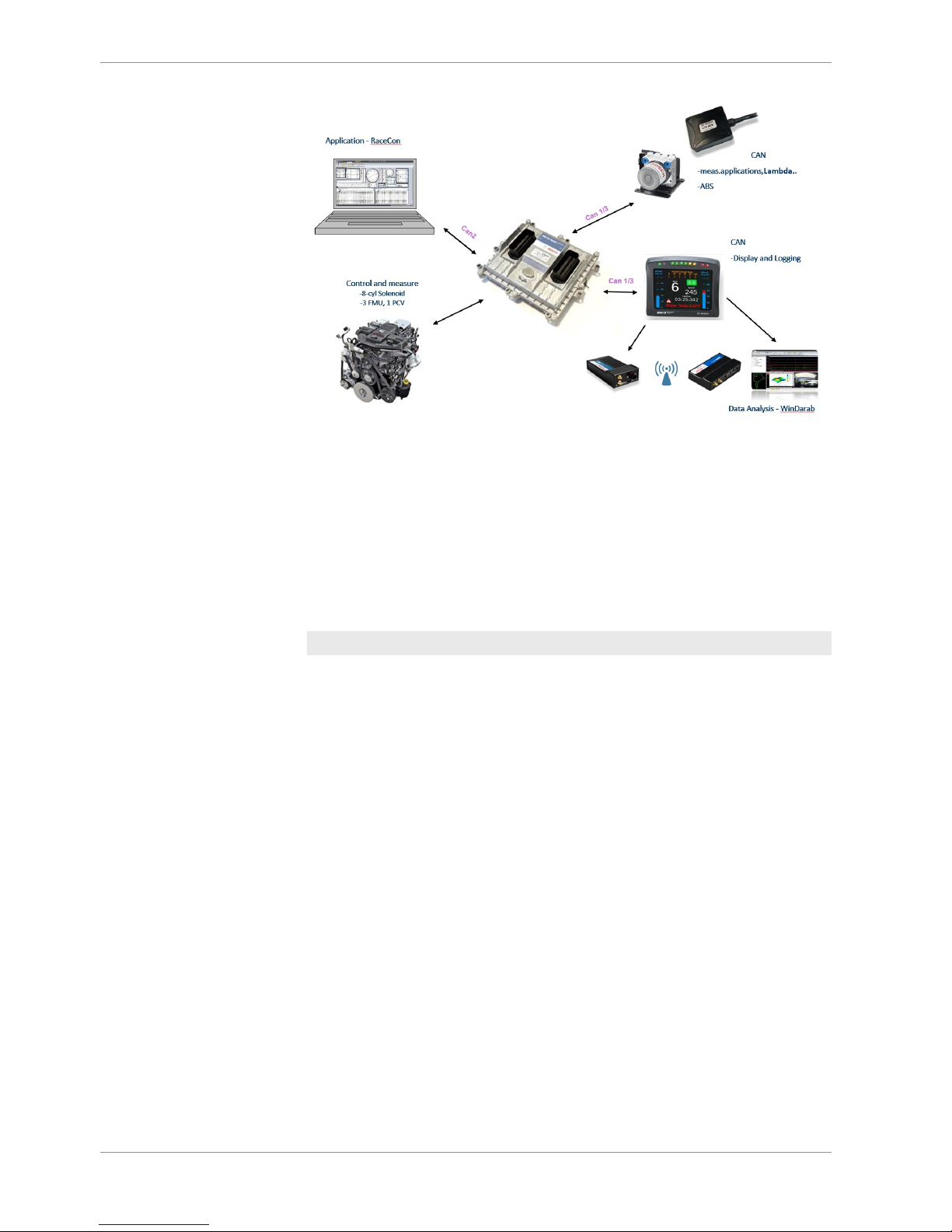
1.2 Application
Installation Notes
Communication
Ordering Information
Engine Control Unit MS 25 Sport F 02U V0U 800-02
Technical data | 1
Bosch Motorsport Engine Control Unit MS 25 Sport 5/40
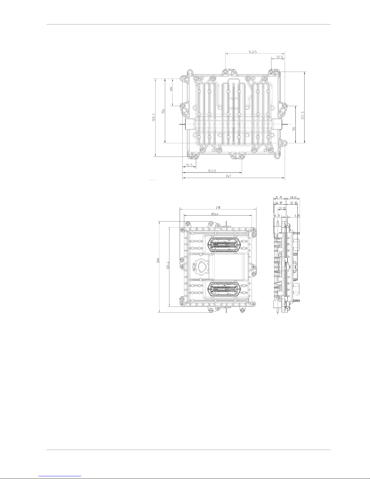
Mechanical Drawing
1.3 Pin Layout
The pin layout is also placed at Bosch Motorsport Homepage.
Some pins and functions are optional and not included in the base version of the MS 25
Sport software.

1 | Technical data
6/40 Engine Control Unit MS 25 Sport Bosch Motorsport
Engine connector (X2 - Engine) 1928405313
PIN Name Main function PIN Name Signal
1 InjectorPwrStg 2 - InjectorPwrStg 2 "bank2" O_P_SVL21
2 InjectorPwrStg 5 - InjectorPwrStg 5 "bank2" O_P_SVL22
3 InjectorPwrStg 8 - InjectorPwrStg 8 "bank2" O_P_SVL23
6 Oil press./temp. gnd Oil Pressure and Temperature Ground G_R_DF03
7 Boost press. supply +5V Boost pressure sensor supply V_V_5VSS1A
8 5V sens. Supply 5 5V Sensor supply 5 V_V_5VSS2C
9 CAM/CRK hall supply +5V CAM/CRK speed sensor supply (HALL) V_V_5VSS2F
10 5V sens. Supply 6 5V sensor supply 6 V_V_5VSS2E
11 rail press. supply +5V Rail pressure sensor supply V_V_5VSS3B
12 Fuel Temp Signal Fuel Temp Signal I_A_AN18 tfuel
13 oil temp. signal Oil temperature sensor signal I_A_AN15 toil
14 fuel feed press. Fuel Feed Pressure I_A_AN09 pfuel
16 exhaust/water1 press. signal Exhaust gas / water pressure 1 I_A_AN02 pwat
17 CAN3+ (Display) CAN Interface (Display/logger) B_D_CANH2
18 CAN3- (Display) CAN Interface (Display/logger) B_D_CANL2
19 Sens. Gnd 5 Sensor ground 5 G_R_AN02
21 waste gate 2 / VGT2 Waste Gate 2 / Variable Turbine Geometry 2 O_T_RL3
22 GPU5 LS General purpose output 5 (LS) O_T_RL07
23 GPU3 LS General purpose output 3 (LS) O_T_RL09
24 Battery plus output 32 Battery Plus Output 32 O_V_RH32
25 InjectorPwrStg 2 + InjectorPwrStg 2 "bank2" O_P_SVH21
26 InjectorPwrStg 5 + InjectorPwrStg 5 "bank2" O_P_SVH22
27 InjectorPwrStg 8 + InjectorPwrStg 8 "bank2" O_P_SVH23
30 Wheelspeed ground Wheel sensor ground rear G_R_AMS
31 oil press. supply +5V Oil pressure sensor supply V_V_5VSS1F
32 Sensor Supply 7 +5V Sensor supply 7 V_V_5VSS1E
33 Water press. Supply +5V Water press sensor supply V_V_5VSS2B
34 5V Sensor supply 8 Sensor supply 8 V_V_5VSS3C
35 oil press. signal Oil pressure sensor input signal I_A_AN01 poil
36 rail press. signal Rail pressure sensor signal I_A_RAILPS prail
37 boost temp. signal MAT (Boost temperature) I_A_AN16 tint
39 coolant temp. signal Coolant temperature sensor signal I_A_AN17 tmot
40 Sensor gnd 8 Sensor ground 8 G_R_AN08
41 SENT (optional) input for SENT interface I_D_SENT
42 Sensor gnd 7 Sensor ground 7 G_R_AN20
45 fuel pump relay Fuel Pump O_S_RL19
46 GPU2 LS General purpose output 2 (LS) O_T_RL06
47 GPU1 LS General purpose output 1 (LS) O_T_RL05
49 InjectorPwrStg 1 + InjectorPwrStg 1 "bank1" O_P_SVH11
50 InjectorPwrStg 4 + InjectorPwrStg 4 "bank1" O_P_SVH12

Technical data | 1
Bosch Motorsport Engine Control Unit MS 25 Sport 7/40
51 InjectorPwrStg 7 + InjectorPwrStg 7 "bank1" O_P_SVH13
52 InjectorPwrStg 3 + InjectorPwrStg 3 "bank3" O_P_SVH32
53 InjectorPwrStg 6 + InjectorPwrStg 6 "bank3" O_P_SVH33
54 fwheel_rl Wheelspeed frequency input, rear left (Hall) I_F_AMS vwheel_rl
55 LIN (OPTIONAL) LIN interface (Optional) B_D_LIN
56 fwheel_rr Wheelspeed frequency input, rear right (Hall) I_F_IATS vwheel_rr
57 waste gate 1 / VGT1 Waste Gate 1 / Variable Turbine Geometry 1 O_T_RL02
58 FMU1 supply Supply FMU O_V_MEU
59 Cooland/fuel temp gnd Coolant and fuel temperature sensor ground G_R_AN18
60 rail press. gnd Rail pressure sensor ground G_R_RAILPS
61 amb/water2 press. signal ambient pressure / water pressure 2 I_A_AN03 pwat2
62 Wastegate press. Signal wastegate pressure sensor 1 signal I_A_AN07 pwgc
63 LSU VM LSU4.9 - VM G_R_LSVG
64 LSU IP LSU4.9 - IP I_A_LSCP
65 crankshaft - Crankshaft speed sensor signal Negative (Inductive) I_F_CRSNEG
66 crankshaft + Crankshaft speed sensor signal Positive (Inductive) I_F_CRSPOS
67 camshaft - (OPTIONAL) Optional CamShaft Sensor Signal (Inductive) I_F_CASNEG
68 camshaft + (OPTIONAL) Optional CamShaft Sensor Signal (Inductive) I_F_CASPOS
69 Sensor gnd 6 Sensor ground 6 G_R_AN07
72 LSU heat- lambda sensor heater low side PWM output O_T_LSH
73 InjectorPwrStg 1 - InjectorPwrStg 1 "bank1" O_P_SVL11
74 InjectorPwrStg 4 - InjectorPwrStg 4 "bank1" O_P_SVL12
75 InjectorPwrStg 7 - InjectorPwrStg 7 "bank1" O_P_SVL13
76 InjectorPwrStg 3 - InjectorPwrStg 3 "bank3" O_P_SVL32
77 InjectorPwrStg 6 - InjectorPwrStg 6 "bank3" O_P_SVL33
78 CAM/CRK (hall) ground CAM/CRK speed sensor ground (Hall) G_R_DF02
79 cam hall signal camshaft position sensor (Hall) I_F_DF02
80 CrankShaft Hall (OPTIONAL) Optional crankshaft speed sensor signal (Hall) I_F_DF06
81 PCV1 (FMU2) LS Rail pressure control valve 1 LS (opt FMU2 LS) O_T_PCV
82 PCV1 Supply Supply PCV1 O_V_PCV
83 FMU1 LS Fuel Metering Unit 1 LS O_T_MEU
84 Sens. Supply 12V Sensor supply O_V_VDD12
86 boost press. signal MAP (boost pressure) I_A_AN05 pboost
87 LSU UN LSU4.9 - UN I_A_LSVN
88 LSU IA LSU4.9 - IA I_A_LSCA
89 Shield GND Shield ground G_R_RES
90 boost press./temp. gnd boost pressure and temperature sensor Ground G_R_AN05
91 turbospeed2+ Turbocharger speed 2 (Inductive) I_F_DF05 nturbo2
92 turbospeed2- Ground for turbocharger speed 2 (Inductive) G_R_DF05
93 turbospeed1+ Turbocharger speed 1 (Inductive) I_F_DF04POS nturbo1
94 turbospeed1- Ground for turbocharger speed 1 (Inductive) I_F_DF04NEG
96 LSU heat+ Battery plus output 22 O_V_RH22

1 | Technical data
8/40 Engine Control Unit MS 25 Sport Bosch Motorsport
Vehicle connector (X1 - Vehicle) 1928405312
PIN Name Main function PIN Name Signal
1 Battery plus 4 Battery plus % V_V_BAT+4
3 Battery minus 1 Battery minus % G_G_BAT-1
5 Battery minus 4 Battery minus % G_G_BAT-4
7 airbox press. signal airbox pressure sensor signal I_A_AN23 pairbox
9 fuel return temp temperature sensor signal for return fuel I_A_AN22 tleak
10 Sensor gnd 1 Sensor Ground 1 G_R_AN10
11 pit speed sw pit speed limiter digital switch I_S_DIG03
14 Launch sw Launch control switch I_S_DIG07
16 egt1 signal Exhaust gas temperature sensor signal 1 I_A_AN13 texh
17 egt2 signal Exhaust gas temperature sensor signal 2 I_A_AN19 texh2
18 egt1/egt2 gnd EGT1 / EGT2 Ground G_R_AN13
21 glowplug relay HS Glowplug Relay HS O_T_RH06
25 Battery plus 3 Battery plus % V_V_BAT+3
26 Battery plus 5 Battery plus % V_V_BAT+5
27 12V Sw/FMU3 (HS) Supply Supply for switches and FMU3 (HS) O_V_RH31
28 Battery minus 2 Battery minus % G_G_BAT-2
32 Map Switch Map position switch I_A_AN24 mapsw
33 Sensor gnd 4 Sensor Ground 4 G_R_AN11
34 Engine Speed Output Engine Speed Output Signal (tach) O_F_DA01
36 Laptrg Laptrigger input I_S_DIG08
37 Pace sw Pace switch I_S_DIG04
39 Sensor gnd 2 Sensor Ground 2 G_R_AN12
40 gearbox temp. signal Gearbox Temperature Sensor Signal I_A_AN14 tgear
41 Ambient temp. signal Ambient Temperature Sensor Signal I_A_AN26 tamb
43 Sensor gnd 3 Sensor Ground 3 G_R_AN14
46 CAN1 + CAN Interface B_D_CANH0
47 CAN1 - CAN Interface B_D_CANL0
49 Battery plus 2 Battery plus % V_V_BAT+2
50 12V Supply Relay (HS) Relay Supply (HS) O_V_RH11
52 Battery minus 5 Battery minus % G_G_BAT-5
53 VSS Vehicle speed sensor signal (Hall) I_F_VSS speed
54 VSS GND Vehicle Speed Sensor Ground G_R_VSS
57 aps2 gnd Accelerator pedal position sensor 2 ground G_R_APP2
60 fuel reset sw Fuel Reset Switch I_S_DIG02
61 MILSpec MILSpec Warning Lamp (LS) O_S_RL20
64 fwheel_fr Wheelspeed frequency input, front right (Hall) I_F_DF01 vwheel_fr
65 Wheel sens. Gnd. Front Wheel Sensor Ground Front G_R_DF01
66 aps1 supply +5V Accelerator pedal supply 1 V_V_5VSS2D
67 5V sens. Supply 4 Sensor Supply 4 V_V_5VSS2A
68 5V sens. Supply 2 Sensor Supply 2 V_V_5VSS1D

Technical data | 1
Bosch Motorsport Engine Control Unit MS 25 Sport 9/40
PIN Name Main function PIN Name Signal
69 terminal 15 Terminal 15 (switched BAT+) I_S_T15
71 CAN 2 + (Diag) CAN Interface (Diag) - MSA-Box2 ecu interface B_D_CANH1
72 MIL MIL Warning Lamp (LS) O_S_RL12
73 Battery plus 1 Battery plus % V_V_BAT+1
75 Battery minus 3 Battery minus % G_G_BAT-3
78 aps2 signal Accelerator pedal position signal 2 I_A_APP2 aps_b
79 aps1 signal Accelerator pedal position signal 1 I_A_APP1 aps_a
80 aps1 gnd Accelerator pedal position sensor 1 ground G_R_APP1
81 Wet sw Wet switch I_S_DIG06
84 fwheel_fl Wheelspeed frequency input, front left (Hall) O_T_RL13 vwheel_fl
86 GPU4 LS General purpose output 4 (LS) O_T_RL08
87 FMU3 LS Fuel Metering Unit 3 LS O_T_RL01
89 Shield GND Shield ground G_G_RL13
90 5V sens. Supply 3 Sensor Supply 3 V_V_5VSS3A
91 5V sens. Supply 1 Sensor Supply 1 V_V_5VSS1C
92 aps2 supply +5V Accelerator pedal supply 2 V_V_5VSS1B
93 Auxiliary Relay LS Auxiliary Relay LS O_S_RL27
94 glowplug relay LS Glowplug Relay LS O_S_RL26
95 CAN 2 - (Diag) CAN Interface (Diag) - MSA-Box2 ecu interface B_D_CANL1
1.4 Input Channels
Only active (0 to 5 V) exhaust gas temperature sensors are supported.
See chapter Initial Data Application [}22] for further information and calibration examples for different sensors.
1.5 Output Channels
The MS 25 Sport has 8 injector power stages on three banks. Only solenoid valve type
common rail injectors are supported. Injector current profile must be calibrated for used
injector type (CRIN1, CRIN3, CRI2.X, ...).
1.6 Power Supply
Please ensure that you have a good ground installation. That means:
– A ground that has a solid, low resistance connection to the battery minus terminal.
– Connection should be free from dirt, grease, paint, anodizing, etc.
– Use large diameter wire.
– More metal-to-metal contact is better
Connection of the power supply
The following notations for power signals are used:
– Term 15 is a switched battery rail controlled by the Engine On-switch.
1 | Technical data
10/40 Engine Control Unit MS 25 Sport Bosch Motorsport
– Term 30 is an unswitched battery positive rail (same as battery positive terminal).
– Term 31 is an unswitched ground rail (same as battery negative terminal).
– MS 25 Sport needs constant Term 30 and ECU should be powered on and off only
with Engine On-switch (Term 15). Constant voltage on Term 30 is required to preserve
critical information during ECU shutdown.
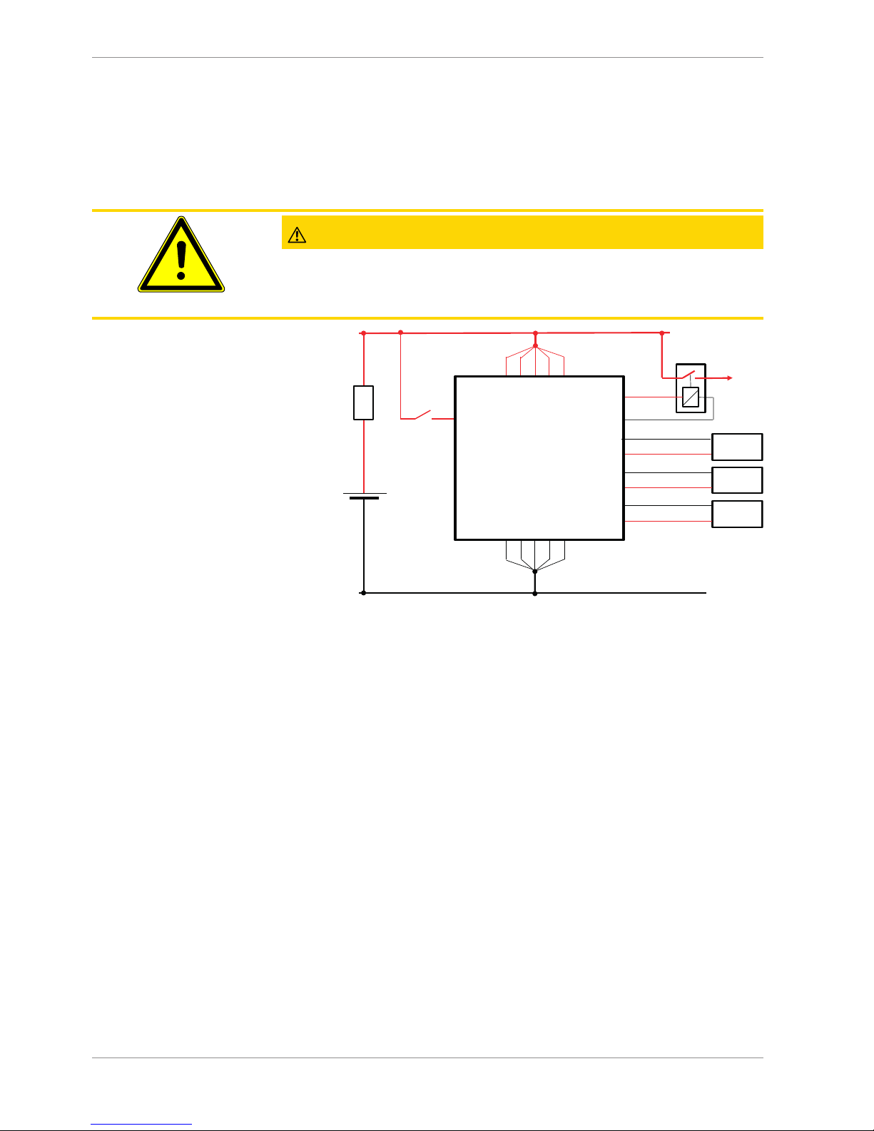
CAUTION
Wrong polarity / high currents
Wrong polarity of the terminals and high currents damage the MS 25 Sport. Be careful to
observe current limits of wires and connector pins!
T30 (UBat)
T31 (GND)
+
-
Battery
Fuse
(30A)
V01 V25 V26 V49 V73
V03 V05 V28 V52 V75
Engine On
Switch
V69
V93
Auxiliary
Relay
PCV
FMU
E83
E58
E81
E82
LSU
Heat
E72
E96
+
+
+
MS 25 Sport
V50
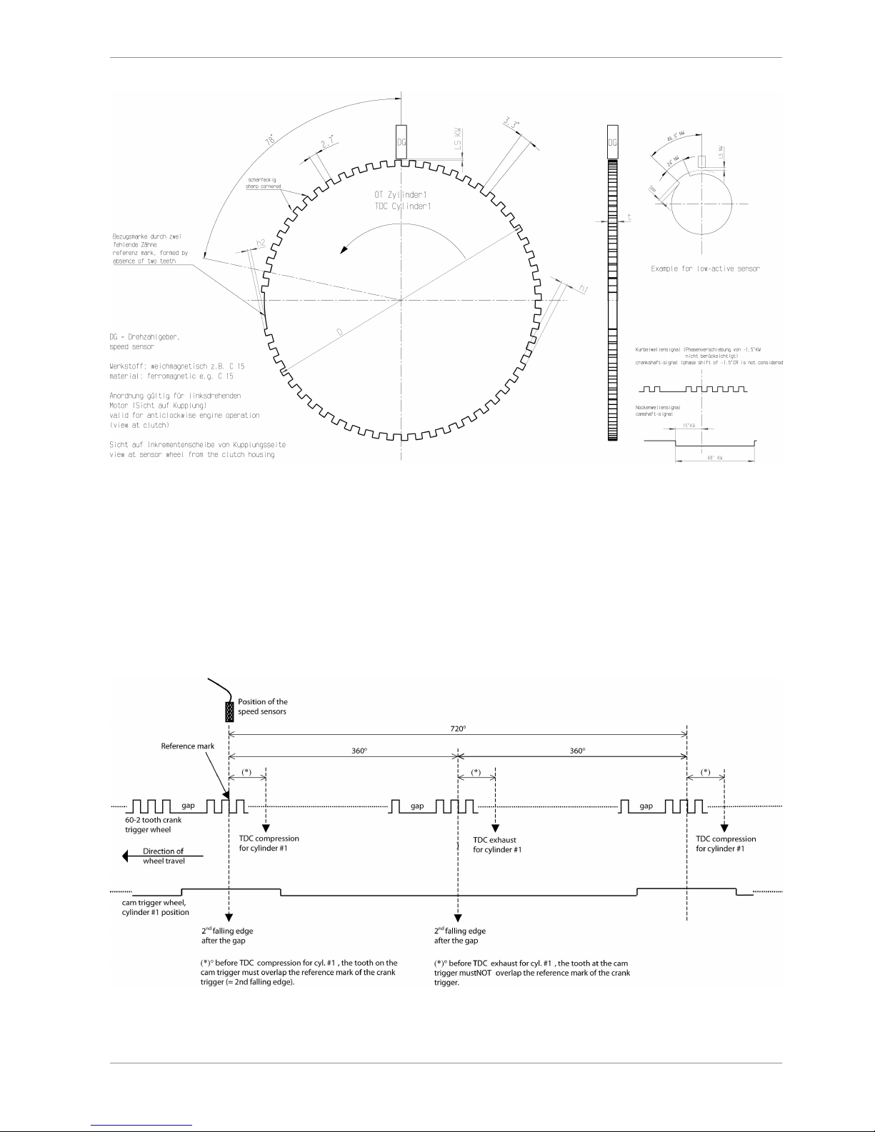
1.7 Trigger Wheel
The software assumes a toothed trigger wheel for proper operation. The number of the
teeth is hard coded by Bosch Motorsport and can’t be changed by the customer. Custom
gap teeth numbers are optional.
We recommend 60 (-2) teeth as shown in the following picture. The crank wheel trigger
sensor must be an inductive type for the default configuration, Hall-effect crank sensor is
optional and requires software change.
The camshaft trigger sensor is a Hall-effect type with a single tooth trigger wheel, but
other configurations can be configured with calibration. Inductive cam sensor is optional
and requires software change. The picture below shows the correct installation position.
Technical data | 1
Bosch Motorsport Engine Control Unit MS 25 Sport 11/40
Recommended values:
– D=min. 160 mm
– h1=3.5 mm
– h2=h1/2
– LSKW=0.8 mm ± 0.3 mm
– t=min. 5 mm
– LSNW=1 mm ± 0.5 mm
The procedure for correct adjustment of the trigger wheel is described in the drawing on
the next page.
Procedure to find the right position for the crank and cam trigger
1. Rotate the engine to the precise position of TDC compression for cylinder #1

1 | Technical data
12/40 Engine Control Unit MS 25 Sport Bosch Motorsport
2. Rotate the engine 78 crankshaft degrees backwards
3. Adjust the position of the crank trigger wheel in reference to its inductive speed
sensor: the longitudinal axis of the sensor must point exactly towards the reference
mark (2nd falling edge after the gap)
4. Rotate the engine further 15 crankshaft degrees backwards
5. Adjust the position of the cam trigger in reference to its Hall Effect speed sensor: the
sensor must be at the begin of the tooth
6. Turn the engine by 345 crankshaft degrees to reach the position of 78° before TDC
exhaust for cylinder #1
7. Verify that the crank trigger reference is in alignment with the longitudinal axis of the
sensor (same as step 3) and that the cam trigger tooth is at the opposite side of its
speed sensor
NOTICE
All angles are shown and indicated in crankshaft degrees
The width of the cam trigger tooth is not important, however it is recommended to use at
least 48 crankshaft degrees (24 cam degrees)
The Hall effect signal may be the inversion of its cam trigger: the tooth effects a “low” signal at the sensor and vice versa for other trigger wheel configurations the indicated values
may vary.
 Loading...