

Page 1
Systems | EA500B Transponder
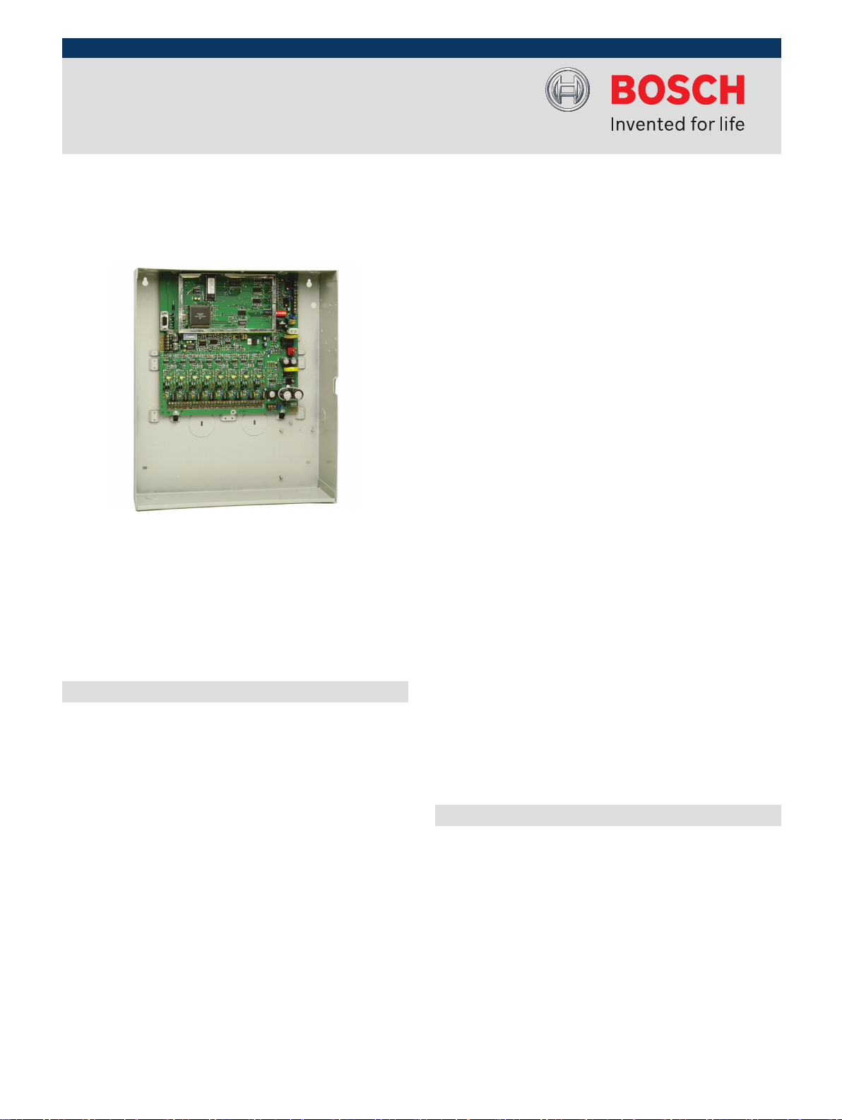
EA500B Transponder
Sends alarm and test signals from the receiver to the
▶
central console
Supports a combined total of 64 receivers and alert
▶
units
Uses AC power with battery backup for all receivers
▶
Provides power to SE485 interface and spread
▶
spectrum radio
Monitors receivers and alert units ten times per
▶
second for alarms, tests, tamper notification, and
power loss
Reports alarms, tests, tamper notification, AC power
▶
loss, and backup battery status
The EA500B Transponder is a device controller for up to
64 devices, any combination of receivers and alert units.
Its primary function is to monitor the receivers and alert
units and report conditions and events to the central
console over wire or ProxLink radios. It also provides
power to certain devices.
Functions
Function During Alarm
When a receiver or alert unit detects an alarm, it goes
•
into an Off‑Normal state. To quickly locate any devices
which might be in the Off‑Normal State, the
transponder issues global commands that are
interpreted simultaneously by all of its devices
approximately ten times per second.
The transponder sends commands to specific devices
•
to determine the nature of the Off‑Normal condition.
During an alarm or test, the transponder sends
commands to obtain the transmitter identification
number, transmitter battery condition, and received
signal strength.
The information is then sent to the central console
•
either by wire or through ProxLink radios, where it
graphically shows the identity and location of the
subscriber (user) sending the alarm.
Configuration
The transponder identifies each receiver and alert unit by
a multiplex address. The address is set during system
installation using a multi-position switch on the receiver
or alert unit circuit board. Transponders communicate on
the data bus with individual multiplex devices by issuing
commands, which contain the receiver or alert unit’s
multiplex address.
Setup and Testing
Each transponder and the devices connected to it are set
up and can be tested remotely from the central console.
Also, each transponder reports any problems, such as low
battery, immediately upon detecting them.
Installation/Configuration Notes
Installation
The transponder is for indoor use only. The transponder
mounts in one of two different sized enclosures. Connect
devices such as receivers, alert units, or combinations of
both to the transponder using eight four‑wire multiplex
buses, two wires for power and two wires for data. Each
bus can support up to eight devices for a combined total
of 64 devices. A Security Escort System supports up to
255 transponders and a total of 16320 devices.
www.boschsecurity.com
Page 2

2 | EA500B Transponder
Compatibility Information
Alert Units: EA120B
Central Console Software: SE2000 Series
Interfaces: Selectable SE485 or RS‑232
Receivers: EA102A‑304
Transmitters: SE2 Series, SE3 Series, SE3401, SE88
Series
Technical Specifications
Transmission
Alarm Output 2 (1 for the strobe and 1 for the si-
ren)
Keyswitch Input Requires optional, supervised loop,
47 kΩ EOL resistor
Mounting Indoor only
Tamper Output NC; optional (CTS1-70)
Trouble Output Through central console
Electrical
Battery Backup: 12 VDC 7 Ah lead acid
Power Output: 9 VDC output for SE485 or for Prox-
Link Radio Module power
Primary Power Requirement: 18 VAC, 50 VA
Environmental
Ordering Information
D126 Standby Battery (12 V, 7 Ah)
D126
Sealed lead‑acid standby and auxiliary rechargeable power supply.
TR1850 Transformer TR1850
Operating Temperature Range: -40°C to +65°C
(-40°F to +149° F)
Ordering Information
EA500B Transponder
Controls receivers and alert units. Relays
alarm and test signals from the receivers to
the central console.
Accessories
AE1 Standard Enclosure (Gray)
Standard gray enclosure with keyed lock.
Measures 35.6 cm x 31.8 cm x 7.6 cm
(14 in. x 12.5 in. x 3 in.).
AE3 Large Enclosure (Gray)
Large gray enclosure with keyed lock. Measures 52.7 cm x 38.1 cm x 10.8 cm (20.7 in.
x 15 in. x 4.25 in.).
CTS1‑70 Tamper Option
Tamper option for the Security Escort
EA500B Transponder.
Americas:
Bosch Security Systems, Inc.
130 Perinton Parkway
Fairport, New York, 14450, USA
Phone: +1 800 289 0096
Fax: +1 585 223 9180
security.sales@us.bosch.com
www.boschsecurity.us
Europe, Middle East, Africa:
Bosch Security Systems B.V.
P.O. Box 80002
5600 JB Eindhoven, The Netherlands
Phone: + 31 40 2577 284
Fax: +31 40 2577 330
emea.securitysystems@bosch.com
www.boschsecurity.com
EA500B
AE1
AE3
CTS1-70
Asia-Pacific:
Robert Bosch (SEA) Pte Ltd, Security Systems
11 Bishan Street 21
Singapore 573943
Phone: +65 6258 5511
Fax: +65 6571 2698
apr.securitysystems@bosch.com
www.boschsecurity.com
Represented by
© Bosch Security Systems Inc. 2011 | Data subject to change without notice
T1177212939 | Cur: en-US, V10, 19 Jan 2011
 Loading...