

Bosch DS935Z Installation Instructions Manual
Installation Instructions
for the DS935Z
ASIC-Based PIR Intrusion Detector
1.0 Specifications
• Input Power: 9.0 VDC to 15.0 VDC
• Current Draw: 15 mA @ 12.0 VDC
• Standby Power: There is no internal standby battery.
Connect to DC power sources
capable of supplying standby power
if primary power fails. For each hour
of standby time needed, 15 mAh are
required. For UL Listed
Requirements, four hours (60 mAh)
minimum are required.
• Coverage:
Broad (standard): 35 ft. x 35 ft. (10.7 m x 10.7 m)
Barrier (optional): 35 ft. x 10 ft. (10.7 m x 3.1 m)
Long Range (optional): 70 ft. x 10 ft. (21.4 m x 3.1 m)
Pet (optional): 35 ft. x 35 ft. (10.7 m x 10.7 m)
with 70 ft. (21.4 m) long range
• Sensitivity: Selectable for Standard or
Intermediate.
• Alarm Relay: Form “C” reed relay with contacts rated
at 28 VDC, 125 mA maximum for DC
resistive loads.
• Tamper Switch: Normally Closed (with cover in place)
tamper switch. Contacts rated at
28 VDC, 125 mA maximum.
• Trouble Output: A solid state open collector shorts to
ground (-) when the detector is in a
trouble condition. The maximum
current load is 25 mA. Vsat @10 mA =
0.5 VDC.
• Temperature: The storage and operating range is
-40°F to +120°F (-40°C to +49°C). For
UL Certificated Installations, the
temperature range is +32°F to +120°F
(0°C to +49°C).
• Options: B335 Low Profile Swivel Mount
Bracket, B338 Ceiling Mount Bracket,
OMB93-3* Barrier Mirror, OMLR93-3*
Long Range Mirror, OMP93-3* Pet
Mirror.
*Shipped in packages of three.
NOTE: Misalignment of the detector when using an optional
mounting bracket may reduce range and increase dead
zones.
• Reading Bosch Security Systems, Inc. Product Date Codes
For Product Date Code information, refer to the Bosch Security
Systems, Inc. Web site at: http://www.boschsecurity.com/datecodes/
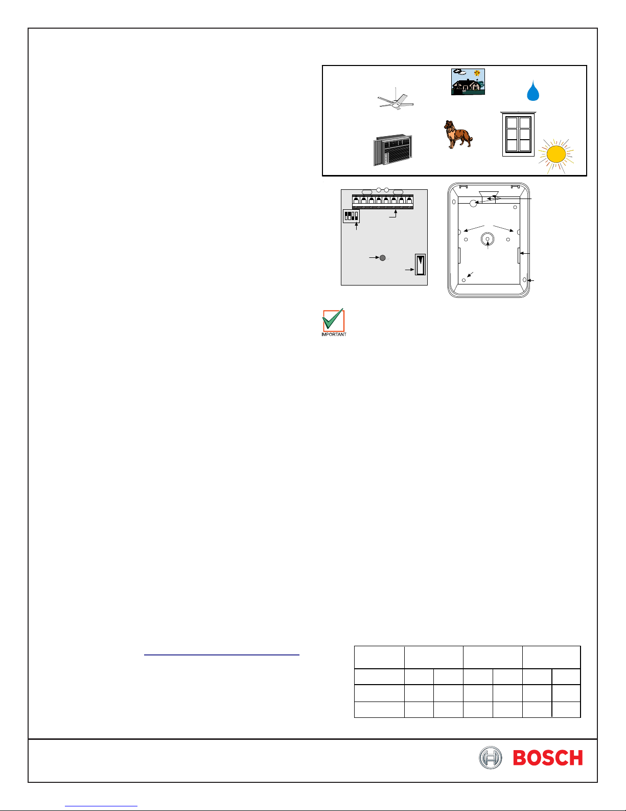
2.0 Mounting
Avoid
Moving objects
Mounting Outdoors
Hot or cold air
directed onto
sensor
Pets or animals
T-Strip
Configuration
Switches
LED
Tamper Switch
Location of major items - Circuit Board
Circuit Board
Retainer Tabs (2)
Bracket Mounting
Hole
Surface
Mounting
Holes (4)
Rear enclosure and mounting holes
The mounting surface should be solid and vibration free.
• Select a location that is most likely to intercept an intruder moving
across the coverage pattern. The recommended mounting
height range is 6.5 ft. to 8.5 ft. (2 m to 2.6 m).
• Remove the cover. Insert a thin flathead screwdriver into the
notch at the bottom of the cover and pry up.
• Remove the circuit board by depressing the circuit board retainer
tab and lifting the board out from the enclosure. Then remove
the mirror by sliding it towards the bottom and out of its tracks.
• Open the knock-out wire entrance and route the wiring through.
3.1 Surface or Corner Mounting
• Open two holes for surface or corner mounting.
• Mark the location for the mounting screws. Use the enclosure
as a template. Pre-start the mounting screws.
• Securely attach the detector.
• Replace the circuit board/mirror unit.
• Select the Vertical Angle.
Mirror Information: The mirror is adjustable from +1° to -18°
vertically by sliding the mirror forward or back and ±10° horizontally
by rocking the mirror side to side. To change the mirror, just pull it
out from its resting grooves.
NOTE: Excessive handling of the mirror surfaces may lead to
performance degradation.
- The following chart will help you set the correct Vertical
Angle based on the mounting height, mirror type, and
desired range.
Mounting
Height
6.5(2)
7.5(2.3)
8.5(2.6)
Broad Barrier Long Range
35(10) 20(6) 35(10) 40(12)
20(6)
-6°
-10°
-12°
-14°
-10°
-6° -4°
-8°
-8° -6° -4°
-12° -8° -6°
Moisture
Direct or
reflected
sunlight
Wiring
Knockouts
Mirror
Tracks (2)
Corner
Mounting
Holes (2)
-4°
70(20)
-2°
-2°
-4°
Height and desired Range li sted in feet (meters)
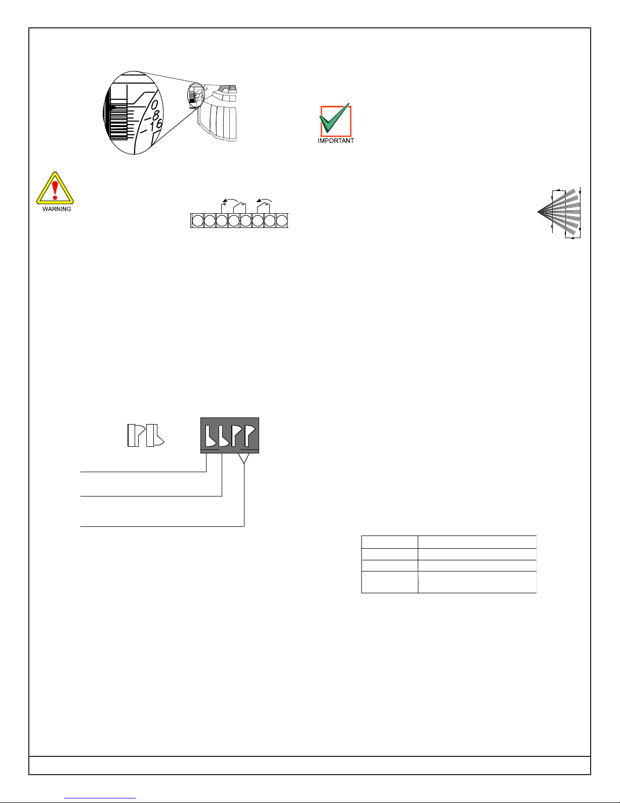
- The angle adjust markings are on the mirror. Slide the
A
mirror forward or back until the angle hash marks are inline with the markers on each side of the frame.
5.3 S3 and S4 - Motion Monitor:
Set for the desired Motion Monitor time (see Supervision
Features). The detector is shipped with the Motion Monitor
feature disabled.
6.0 Setup and Walk Testing
Before walk testing, the system should be fully wired,
powered, and programmed.
3.0 Wiring
Only apply power after all connections have been
made and inspected.
• Connect wiring as shown.
larmAlarm
1 2 3 4 5 6 7 8
+
NO C NC TT
-
TR
NOTE: Do not coil excess wiring inside unit.
• Seal the Wire Entrance using the foam plug provided.
Terminal Descriptions
• 1 (-) & 2 (+): Input Power. Use no smaller than #22 AWG
(0.8 mm) wire pair.
• 3, 4, 5: Form "C" reed relay contacts rated at 3 W, 125 mA,
28 VDC maximum for DC resistive loads and protected by a
4.7 ohm resistor in the common "C" leg of the relay. Do not use
with capacitive or inductive loads.
• 6 & 7: Tamper Contact, rated 28 VDC, 125 mA.
• 8: Trouble. Solid state open collector; maximum current load is
25 mA. Shorts to ground (-) when the detector is in a Trouble
condition.
5.0 Configuring Detector
OFF
ON
(ON) 1
(OFF) 0
1 ON = LED ON
1 OFF = LED OFF
2 ON = Standard
2 OFF = Inte r mediate
3 ON and 4 OFF = 4 Day Motion Monitor
3 OFF and 4 ON = 30 Day Motion Monitor
3 OFF and 4 OF F = Motion Monitor D isab le d
5.1 S1 - LED Operation
• ON: Allows the LED to operate when activated by alarm.
• OFF: The LED will not operate on alarm.
5.2 S2 - Sensitivity Mode
• Standard Sensitivity: Recommended setting for maximum
false alarm immunity. Tolerates environment extremes on this
setting. Not recommended for Long Range or Barrier type
patterns. The detector is shipped in Standard Sensitivity
mode.
• Intermediate Sensitivity: Recommended setting for any location
where an intruder is expected to cover only a small portion of the
protected area. Tolerates normal environments on this setting.
This setting will improve your intruder catch performance.
12 34
OPEN
• Turn LED Switch ON.
• Replace the front cover.
NOTE: All testing must be performed with the front
cover in place.
• Wait at least two minutes (with no motion in the
coverage area) for the detector to setup.
• Walk test across the coverage pattern.
• The edge of the coverage is determined by activation of the
LED.
• Walk test the unit from both directions to determine the
boundaries.
7.0 Supervision Features
A supervision trouble condition is indicated at the detector by the
LED. The LED indicates the cause of the trouble using coded
pulses. The trouble signal activates the Trouble output available
at Terminal 8, which should be connected to a 24-hour zone.
The supervision features function as follows:
• PIR: PIR operation is checked electronically approximately every
12 hours. If the circuit fails, the LED will pulse four times, the
Trouble output will activate and the unit must be replaced.
• Motion Monitor Supervision: This feature verifies that the
detector has a clear view of the detection area.
- When selected, a supervision timer is activated. A trouble
condition will be indicated if the detector has not alarmed at
least once during the selected time period (this feature can be
disabled by placing both switches [S3 and S4] in the OFF
position). The time period selected should be long enough to
allow adequate time for holiday weekends.
- If the time period selected has elapsed from the last alarm,
the LED will flash two times and the Trouble output will activate.
The following chart displays the LED response to the supervision
features:
LED
ON
Two Flashes
Four Flashes
Cause
Unit Alarm
Motion Monitor Timeout
PIR Self-Test Failure
(replace detector)
• Trouble Reset: An alarm activation will reset a motion monitor
trouble condition.
8.0 Maintenance
At least once a year, the range and coverage should be checked
in accordance with the Walk Testing section. To ensure continual
daily operation, the end user should be instructed to daily walk
through the outer edge of the coverage pattern and observe the
LED operation (if used). This assures an alarm output prior to
arming.
Page 2 © 2011 Bosch Security Systems, Inc. DS935Z Installation Instructions
 Loading...