


Bosch DCN Next Generation, DCN Installation And Operation Manual
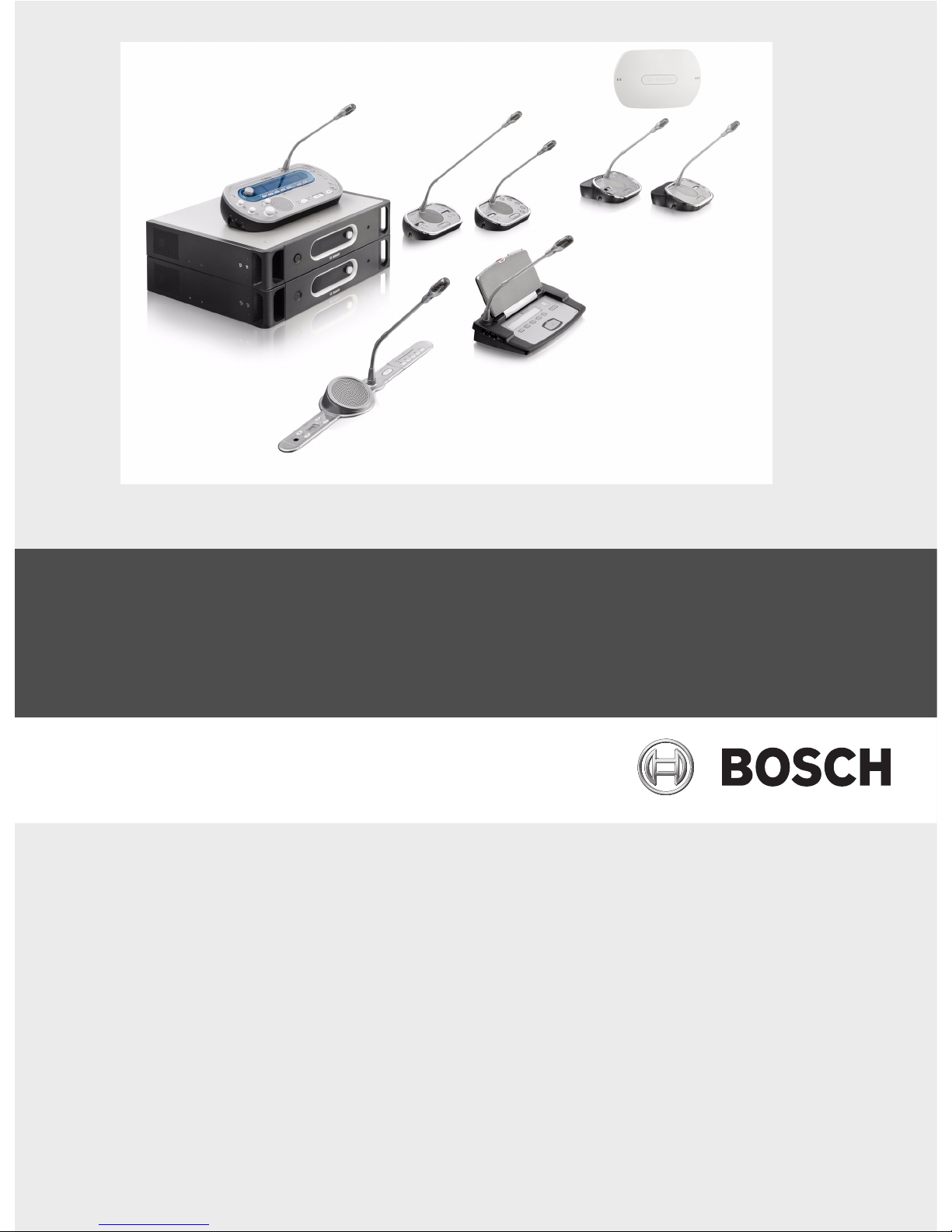
Conference System
DCN Next Generation
en Installation and Operation manual


Conference System Table of Contents | en 3
Bosch Security Systems B.V. Installation and Operation manual DCN-NG_IOM_V4.1 | V1.3 | 2012.07
Table of Contents
1Safety 9
1.1 Important Safeguards 9
1.2 DCN-WLIION Battery Pack 9
1.3 Disclaimers 9
1.4 Statements for FCC & Industry Canada 9
2 About this manual 11
2.1 Function 11
2.2 Digital version 11
2.3 Precautions and notes 11
2.4 Signs 11
2.5 Electro-static discharges 12
2.6 Conversion tables 13
3System Overview 14
3.1 DCN-CCU2 and DCN-CCUB2 Central Control Units 15
3.1.1 Audio I/O routing 17
3.2 LBB4402/00 Audio Expander 23
3.3 PRS-4DEX4 Digital Audio Expander 24
3.4 LBB4404/00 Cobranet Interface 25
3.5 DCN-WAP Wireless Access Point 27
3.6 DCN-CON Concentus Units 28
3.7 DCN-DIS and DCN-WD Discussion Units 32
3.8 DCN-WLIION Battery Pack 37
3.9 DCN-WCH05 Battery Charger 38
3.10 DCN-WPS Power Supply Adapter 38
3.11 DCN-MICL, DCN-MICS Pluggable Microphones 39
3.12 DCN-ICHS Intercom Handset 40
3.13 DCN-FPT Flush Positioning Tool 41
3.14 DCN-DDI Dual Delegate Interface 41
3.15 DCN-FMIC Microphone Connection Panel 42
3.16 DCN-FMICB Microphone Control Panel 43
3.17 DCN-FPRIOB Priority Panel 43
3.18 DCN-FLSP Loudspeaker Panel 44
3.19 DCN-FV(CRD) Voting Panel 45
3.20 DCN-FCS Channel Selector 46
3.21 DCN-FVU Voting Unit 48
3.22 DCN-FCOUP Couple 50
3.23 DCN-FEC End Caps 50
3.24 DCN-TTH Tabletop Housing 51
3.25 DCN-FBP panels 51
3.26 DCN-IDESK Interpreter Desks 52
3.27 DCN-EPS Extension Power Supply 55
3.28 LBB4114/00 Trunk Splitter 56
3.29 LBB4115/00 Tap-off unit 57
3.30 LBB4116 Extension Cables 57

4 en | Table of Contents Conference System
DCN-NG_IOM_V4.1 | V1.3 | 2012.07 Installation and Operation manual Bosch Security Systems B.V.
3.31 LBB4117/00 Cable Locking Clamps 58
3.32 LBB4118/00 Cable Termination Plug 58
3.33 PRS-NSP Network Splitter 59
3.34 PRS-FINNA Fiber Interface 61
3.35 LBB4416 Optical Network Cables 62
3.36 LBB4418/00 Cable-connector Tool Kit 64
3.37 LBB4419/00 Cable Couplers 65
3.38 DCN-DDB Data Distribution Board 65
3.39 DCN-IDENC ID-card Encoder 66
3.40 DCN-IDCRD ID-cards 66
4 Planning 67
4.1 DCN design 67
4.1.1 Calculation tool 67
4.1.2 Concepts 67
4.1.3 Limits 67
4.1.4 Control capacity 69
4.1.5 Power capacity 70
4.1.6 Maximum power consumption 72
4.1.7 Examples 74
4.1.8 Interpretation devices 77
4.2 Optical network design 78
4.2.1 Calculation tool 78
4.2.2 Limits 78
4.2.3 Control capacity 79
4.2.4 Power capacity 79
4.2.5 Cabling 81
4.2.6 Optical fiber length 81
4.2.7 Cable couplers 82
4.2.8 Bending Network Cable 82
4.2.9 Example layouts 83
4.3 Wireless network design 86
4.3.1 Limits 86
4.3.2 Frequency band 86
4.4 Wireless language distribution 88
4.5 CobraNet 88
4.6 User set-up 89
4.6.1 Public areas 89
4.6.2 Speaking distance 89
4.6.3 Interpreter booths 89
4.7 Device set-up 90
4.7.1 General 90
4.7.2 Cables 90
4.7.3 Temperature 90
4.7.4 Ventilation 90
4.7.5 Acoustic feedback 90
5 Installation 91
5.1 19 inch units 91

Conference System Table of Contents | en 5
Bosch Security Systems B.V. Installation and Operation manual DCN-NG_IOM_V4.1 | V1.3 | 2012.07
5.2 DCN-WAP Wireless Access Point 91
5.3 DCN-CON Concentus Units 95
5.4 DCN-DIS and DCN-WD Discussion units 96
5.5 DCN-WCH05 Battery Charger 101
5.6 DCN-Flush mounted products 104
5.7 DCN-IDESK Interpreter Desks 109
5.8 DCN-EPS Extension Power Supply 110
5.9 LBB4114/00 Trunk Splitter 111
5.10 LBB4115/00 Tap-off unit 111
5.11 PRS-NSP Network Splitter 111
5.12 PRS-FINNA Fiber Interface 111
6 Connection 112
6.1 19 inch Units 112
6.2 DCN-CCU2 and DCN-CCUB2 Central Control Units 113
6.3 LBB4402/00 Audio Expander 117
6.4 PRS-4DEX4 Digital Audio Expander 120
6.5 LBB4404/00 Cobranet Interface 122
6.6 DCN-WAP Wireless Access Point 123
6.7 DCN Concentus Units 124
6.8 DCN-DIS Discussion Unit (wired) 127
6.9 DCN-WD Discussion Units (wireless) 128
6.10 DCN-WCH05 Battery Charger 130
6.11 DCN-MICL, DCN-MICS Pluggable Microphones 131
6.12 DCN-DDI Dual Delegate Interface 132
6.13 DCN-FMIC Microphone Connection Panel 134
6.14 DCN-FMICB Microphone Control Panel 134
6.15 DCN-FPRIOB Priority Panel 134
6.16 DCN-FLSP Loudspeaker Panel 134
6.17 DCN-FV(CRD) Voting Panel 134
6.18 DCN-FCS Channel Selector 137
6.19 DCN-FVU Voting Unit 139
6.20 DCN-IDESK Interpreter Desks 139
6.21 DCN-EPS Extension Power Supply 141
6.22 LBB4114/00 Trunk Splitter 143
6.23 LBB4115/00 Tap-off unit 143
6.24 PRS-NSP Network Splitter 144
6.25 PRS-FINNA Fiber Interface 146
6.26 DCN-DDB Data Distribution Board 148
6.27 Custom made Optical Network Cables 157
6.28 Custom made DCN cables 172
7 Configuration 173
7.1 System Configuration 173
7.1.1 Downloading 173
7.1.2 Initialization 174
7.2 19 inch units 175
7.3 DCN-CCU2 and DCN-CCUB2 Central Control Units 179
7.4 LBB4402/00 Audio Expander 186

6 en | Table of Contents Conference System
DCN-NG_IOM_V4.1 | V1.3 | 2012.07 Installation and Operation manual Bosch Security Systems B.V.
7.5 PRS-4DEX4 Digital Audio Expander 189
7.6 LBB4404/00 Cobranet Interface 192
7.7 CobraNet Discovery 195
7.8 CNConfig 198
7.9 DCN-WAP Wireless Access Point 203
7.10 DCN-CON Concentus Units 205
7.11 DCN-DIS and DCN-WD discussion units 206
7.12 DCN-DDI Dual Delegate Interface 211
7.13 DCN-FMIC Microphone Connection Panel 216
7.14 DCN-FCS Channel Selector 217
7.15 DCN-IDESK Interpreter Desks 219
7.16 DCN-EPS Extension Power Supply 224
7.17 PRS-NSP Network Splitter 225
7.18 DCN-DDB Data Distribution Board 226
8Operation 229
8.1 System operation DCN-Wireless 229
8.1.1 Start the system 229
8.1.2 Stop the system 230
8.2 DCN-CCU2 and DCN-CCUB2 Central Control Units 230
8.3 LBB4402/00 Audio Expander 236
8.4 PRS-4DEX4 Digital Audio Expander 238
8.5 LBB4404/00 Cobranet Interface 240
8.6 DCN-WAP Wireless Access Point 242
8.7 DCN-CON Concentus Units 244
8.8 DCN-DIS and DCN-WD Discussion Units 244
8.9 DCN-WLIION Battery Pack 246
8.10 DCN-WCH05 Battery Charger 246
8.11 DCN-MICL, DCN-MICS Pluggable Microphones 246
8.12 DCN-FMICB Microphone Control Panel 247
8.13 DCN-FPRIOB Priority Panel 247
8.14 DCN-FV(CRD) Voting Panel 248
8.15 DCN-FVU Voting Unit 248
8.16 DCN-IDESK Interpreter Desks 249
8.17 PRS-NSP Network Splitter 253
8.18 PRS-FINNA Fiber Interface 253
8.19 DCN-DDB Data Distribution Board 253
9Troubleshooting 257
9.1 System 257
9.2 DCN-CCU2 and DCN-CCUB2 Central Control Unit 259
9.3 DCN-CON Concentus Unit 260
9.4 DCN-DIS Discussion Unit 261
9.5 DCN-WD Wireless Discussion Unit 261
9.6 LBB4114/00 or LBB4115/00 Network Splitter 262
9.7 PC control software 262
9.8 LBB 4402/00 Audio Expander 262
9.9 DCN-WAP Wireless Access Point 263
9.10 DCN-MIC Microphones 263

Conference System Table of Contents | en 7
Bosch Security Systems B.V. Installation and Operation manual DCN-NG_IOM_V4.1 | V1.3 | 2012.07
9.11 DCN-F Flush Mounted units 263
9.12 DCN-DDB Data Distribution Board 264
10 Maintenance 265
10.1 Cleaning 265
10.2 Storage 265
10.3 DCN-WLIION Battery Pack 265
11 Technical Data 266
11.1 System Technical Data 266
11.1.1 Transmission links 266
11.1.2 Combined devices from input to output 266
11.1.3 Safety 266
11.1.4 Electro-magnetic compatibility 267
11.1.5 Wireless devices 267
11.1.6 Miscellaneous 268
11.1.7 Language list 269
11.2 Product Technical Data 272
11.2.1 DCN-CCU2 and DCN-CCUB2 Central Control Units 272
11.2.2 LBB4402/00 Audio Expander 273
11.2.3 PRS-4DEX4 Digital Audio Expander 274
11.2.4 LBB4404/00 Cobranet Interface 274
11.2.5 DCN-WAP Wireless Access Point 275
11.2.6 DCN-CON Concentus Units 275
11.2.7 DCN-DIS and DCN-WD Discussion Units 276
11.2.8 DCN-WLIION Battery Pack 276
11.2.9 DCN-WCH05 Battery Charger 276
11.2.10 DCN-WPS Power Supply Adapter 277
11.2.11 DCN-MICL, DCN-MICS Pluggable Microphones 277
11.2.12 DCN-ICHS Intercom Handset 278
11.2.13 DCN-FPT Flush Positioning Tool 278
11.2.14 DCN-DDI Dual Delegate Interface 279
11.2.15 DCN-FMIC Microphone Connection Panel 279
11.2.16 DCN-FMICB Microphone Control Panel 279
11.2.17 DCN-FPRIOB Priority Panel 279
11.2.18 DCN-FLSP Loudspeaker Panel 280
11.2.19 DCN-FV(CRD) Voting Panel 280
11.2.20 DCN-FCS Channel Selector 280
11.2.21 DCN-FVU Voting Unit 280
11.2.22 DCN-FCOUP Couple 280
11.2.23 DCN-FEC End Caps 281
11.2.24 DCN-TTH Tabletop Housing 281
11.2.25 DCN-FBP panels 281
11.2.26 DCN-IDESK Interpreter Desks 281
11.2.27 DCN-EPS Extension Power Supply 282
11.2.28 LBB4114/00 Trunk Splitter 282
11.2.29 LBB4115/00 Tap-off unit 282
11.2.30 LBB4116 Extension Cables 282
11.2.31 LBB4416 Optical Network Cables 283

8 en | Table of Contents Conference System
DCN-NG_IOM_V4.1 | V1.3 | 2012.07 Installation and Operation manual Bosch Security Systems B.V.
11.2.32 DCN-DDB Data Distribution Board 283
11.2.33 DCN-IDENC Chip Card Encoder 283
Conference System Safety | en 9
Bosch Security Systems B.V. Installation and Operation manual DCN-NG_IOM_V4.1 | V1.3 | 2012.07
1Safety
1.1 Important Safeguards
Please read the Important Safety Instructions before you install or operate the DCN System.
The Important Safety Instructions are supplied together with the central control unit.
1.2 DCN-WLIION Battery Pack
Figure 1.1 Safety instructions
When wireless discussion units with DCN-WLIION battery packs are used, read safety
instructions as printed on the label of the battery pack.
1.3 Disclaimers
CobraNet is a trademark of Peak Audio — a division of Cirrus Logic, Inc. — in the United States
and/or other countries.
1.4 Statements for FCC & Industry Canada
This Class B digital apparatus complies with Canadian ICES-003. Cet appareil numérique de la
classe B est conforme à la norme NMB-003 du Canada.
The DCN wireless equipment has been tested and found to comply with the limits for a Class
B digital device, pursuant to Part 15 of the FCC Rules. These limits are designed to provide
reasonable protection against harmful interference in a residential installation. This
equipment generates, uses and can radiate radio frequency energy and, if not installed and
used in accordance with the instructions, may cause harmful interference to radio
communications. However, there is no guarantee that interference will not occur in a
particular installation. If this equipment does cause harmful interference to radio or television
reception, which can be determined by turning the equipment off and on, the user is
encouraged to try to correct the interference by one or more of the following measures:
– Reorient or relocate the receiving antenna.
– Increase the separation between the equipment and receiver.
– Connect the equipment into an outlet on a circuit different from that to which the
receiver is connected.
– Consult the dealer or an experienced radio/TV technician for help.
The Wireless Discussion Units and the Wireless Access Point comply with Part 15 of the FCC
Rules and with RSS-210 of Industry Canada. Operation is subject to the following two
conditions:
1. This device may not cause harmful interference.
2. This device must accept any interference received, including interference that may cause
undesired operation.
CAUTION Important Safety Instructions for Li-ion batteries.
Do not short-circuit the battery.
Do not pierce or crush the battery.
Do not disassemble or modify the battery.
Do not heat, incinerate or expose the battery to direct continuous sunshine.
Do not immerse the battery in any liquid it may be vent or rupture.
Respect charging, discharging, transport and storage instructions.
Charge the battery between 0 ºC and 45 ºC (32ºF and 113ºF).
Discharge the battery between -20 ºC and 60 ºC (-4ºF and 140ºF).
Rated : 7.2V 4800 mAh
Charging Current : 12V/2.5A
DCN-WLIION-D Rechargeable Lithium-ion Battery Pack
NL-4827HG-10
S/N: SMYYWW9999
Li-ion
US ITE ACCESORYC
LISTED
19JW
M
04

10 en | Safety Conference System
DCN-NG_IOM_V4.1 | V1.3 | 2012.07 Installation and Operation manual Bosch Security Systems B.V.
NOTICE!
Changes or modifications made to this equipment, not expressly approved by Bosch Security
Systems B.V. may void the FCC authorization to operate this equipment.
NOTICE!
The Wireless Discussion Units and the Wireless Access Point comply with FCC radiation
exposure limits set forth for an uncontrolled environment. The Wireless Discussion Units and
the Wireless Access Point should be installed and operated with minimum distance of 20 cm
to your body. The RF-parts of the Wireless Discussion Units and the Wireless Access Point
must not be co-located or operating in conjunction with any other antenna or transmitter.
Conference System About this manual | en 11
Bosch Security Systems B.V. Installation and Operation manual DCN-NG_IOM_V4.1 | V1.3 | 2012.07
2 About this manual
2.1 Function
The Installation and Operation manual gives the installers and the operators the necessary
data to install, configure and operate the DCN System.
2.2 Digital version
The Installation and Operation manual is available as a digital file (Portable Document Format,
PDF). When the PDF refers to a location that contains more data, click the text. The text
contains hyperlinks.
2.3 Precautions and notes
The Installation and Operation manual uses precautions and notes. The precaution gives the
effect if you do not obey the instructions.
These are the types:
– Note: A note gives more data.
– Caution: If you do not obey the caution, you can cause damage to the equipment.
– Warning: If you do not obey the warning, you can cause personal injury or death.
2.4 Signs
The Installation and Operation manual shows each precaution with a sign. The sign shows the
effect if you do not obey the instruction.
The sign that is shown along with a note gives more data about the note itself.
WARNING!
General sign for cautions and warnings.
DANGER!
Risk of electric shock.
WARNING!
Risk of electro-static discharges (refer to Section 2.5 Electro-static discharges).
NOTICE!
General sign for notes.
NOTICE!
Refer to another information source.
12 en | About this manual Conference System
DCN-NG_IOM_V4.1 | V1.3 | 2012.07 Installation and Operation manual Bosch Security Systems B.V.
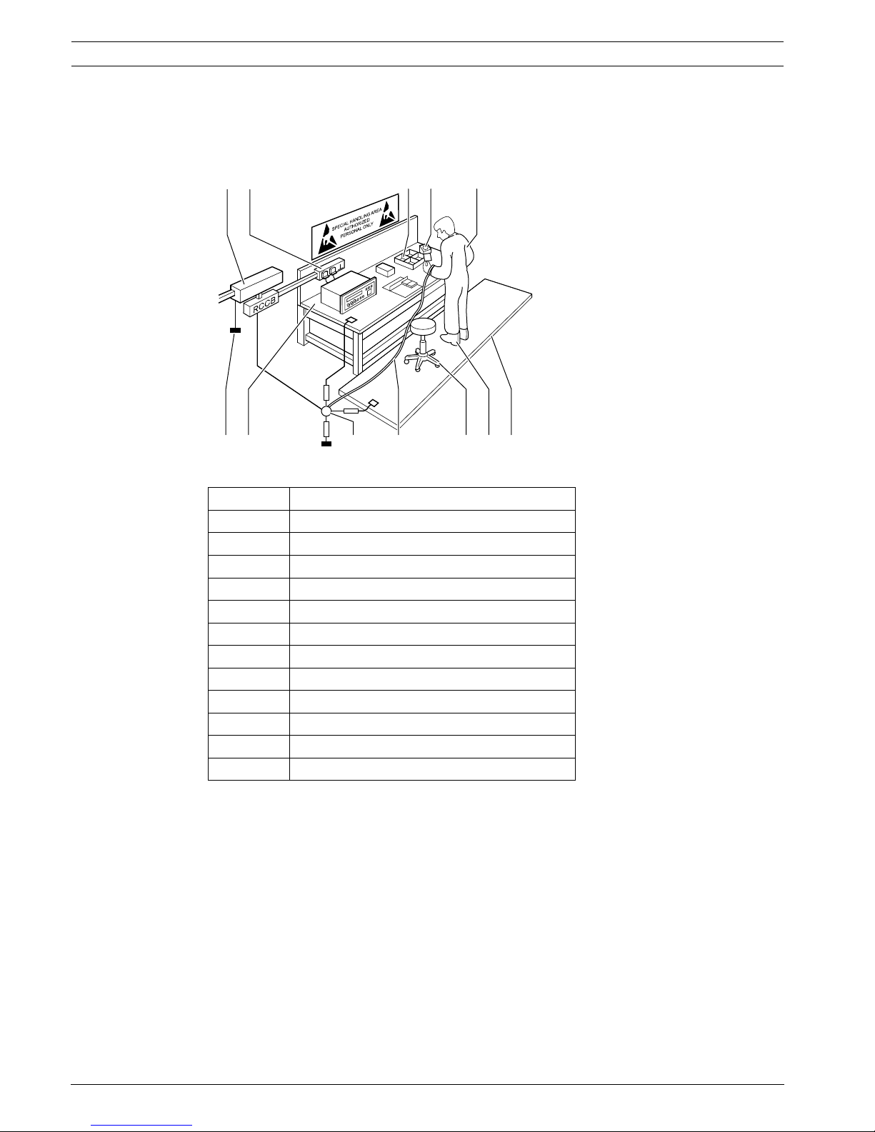
2.5 Electro-static discharges
Electro-Static Discharges (ESD) can damage electric components. Take precautions to
prevent electro-static discharges when touch PCBs.
Figure 2.1 ESD prevention
Tab le 2. 1 ESD prevention
No. Description
1 Safety isolating transformer
2 Distribution supply box
3 Conductive compartment trays
4 Electro-static voltage sensor
5 Cotton overall
6 Conductive floor mat
7 Conductive boots/heel grounding protectors
8 Conductive stool
9 Strap (resistance 0.5 to 1.0 MΩ)
10 Common reference point
11 Conductive bench top
12 Supply ground
312
12
11 10 9 8 7 6
4 5
Conference System About this manual | en 13
Bosch Security Systems B.V. Installation and Operation manual DCN-NG_IOM_V4.1 | V1.3 | 2012.07
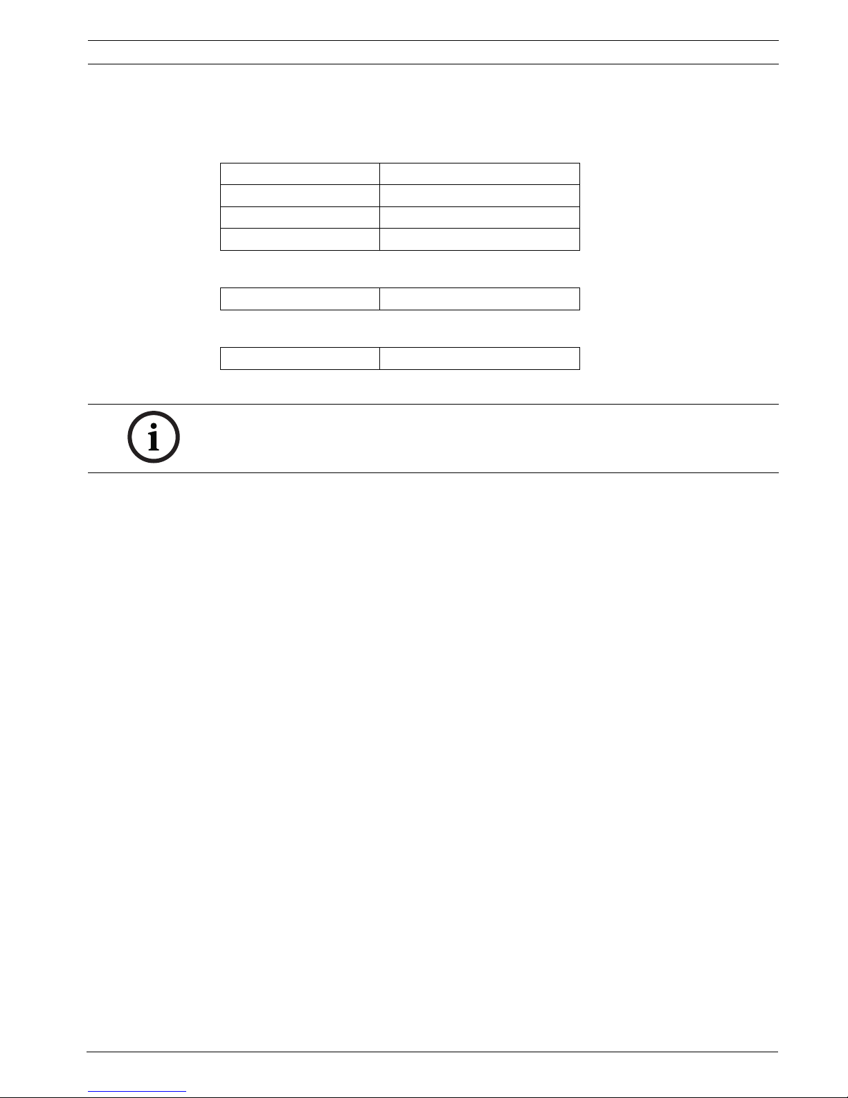
2.6 Conversion tables
Length, mass and temperature are in SI units. Refer to the following tables to change SI units
to imperial units.
Tab le 2. 2 Conversion of units of length
Tab le 2. 3 Conversion of units of mass
Tab le 2. 4 Conversion of units of pressure
1 in = 25.4 mm 1 mm = 0.03937 in
1 in = 25.4 mm 1 cm = 0.3937 in
1 ft = 0.3048 m 1 m = 3.281 ft
1 mi = 1.609 km 1 km = 0.622 mi
1 lb = 0.4536 kg 1 kg = 2.2046 lb
1 psi = 68.95 hPa 1 hPa = 0.0145 psi
NOTICE!
1 hPa = 1 mbar.
14 en | System Overview Conference System
DCN-NG_IOM_V4.1 | V1.3 | 2012.07 Installation and Operation manual Bosch Security Systems B.V.
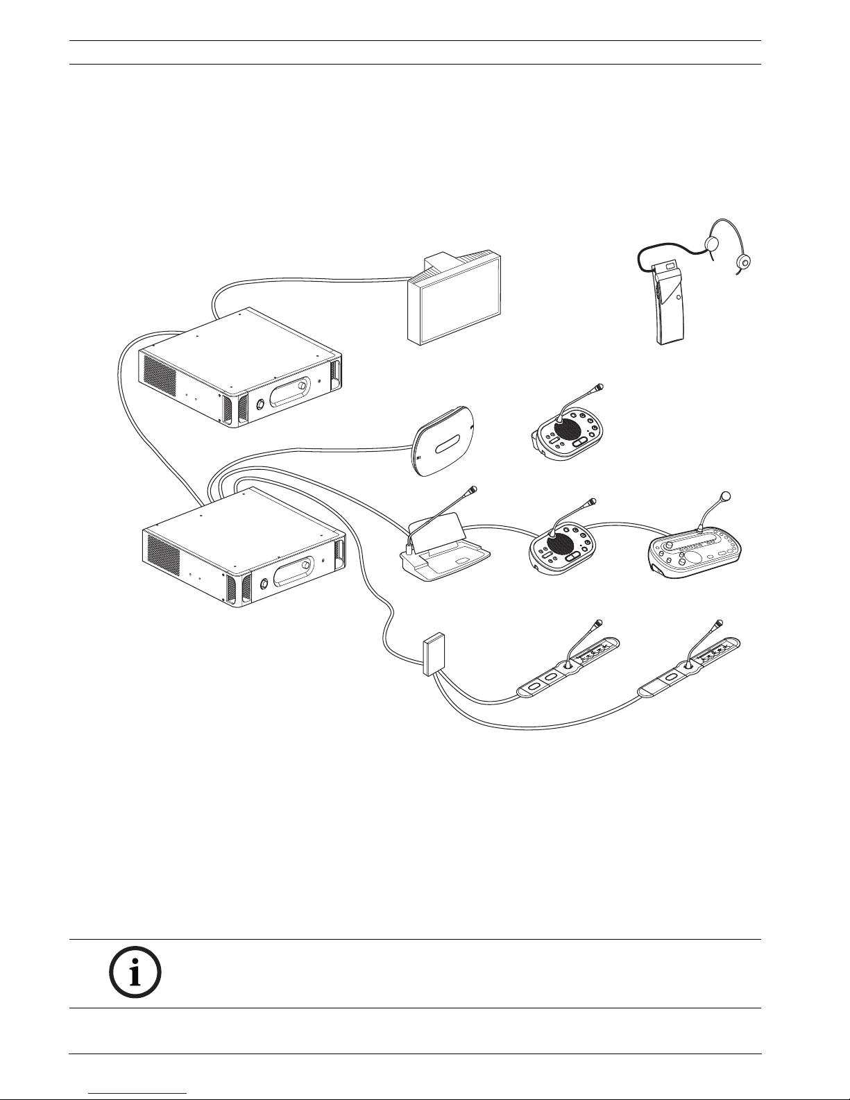
3 System Overview
The DCN System is a system for wired and wireless distribution and processing of audio
signals. The system can also be used for voting and simultaneous interpretation.
The DCN System is composed of three parts: the DCN network, the wireless network and the
optical network.
Figure 3.1 DCN System system overview
The DCN System comprises:
– Central control units, audio expanders, Integrus transmitter and/or wireless access
point.
– Wireless discussion units, wired discussion units, Consentus units, flush mounted units
and/or interpreter desks.
– Installation devices, such as Dual Delegate Interfaces (DDI) and extension power supply
units, trunk splitters.
NOTICE!
Refer to the Integrus manual for all related information.
Conference System System Overview | en 15
Bosch Security Systems B.V. Installation and Operation manual DCN-NG_IOM_V4.1 | V1.3 | 2012.07
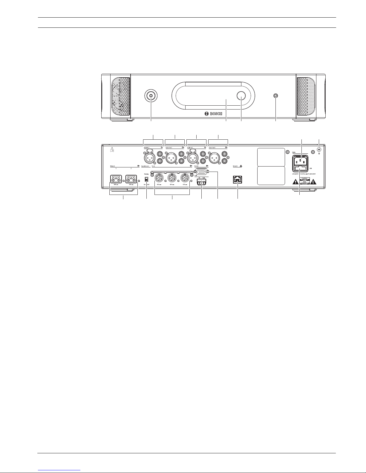
3.1 DCN-CCU2 and DCN-CCUB2 Central Control Units
The Central Control Unit controls the system. The Central Control Unit can operate with or
without a control PC.
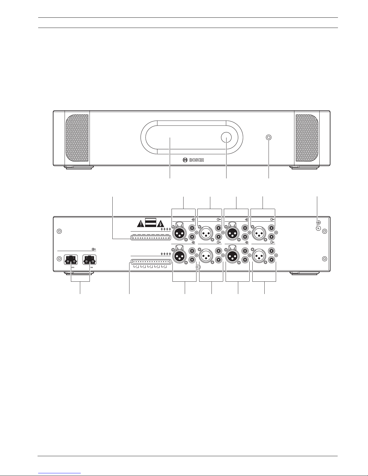
Figure 3.2 Front and rear view of CCU2
The front of the central control unit contains:
1. On/off switch - Power on or off the central control unit.
2. Display - Shows the configuration menu.
3. Knob - Operates the configuration menu and the volume level of the system.
4. Headphones socket - Headphone connection.
The rear of the central control unit contains:
5. Audio inputs - Connect the central control unit to external analog audio sources. The
functions of the audio inputs are:
– Audio input 1: Floor
Audio input 2: Selectable recorder/delegate loudspeaker/ mix-minus/insertion.
Interpreter floor insertion/local floor.
6. Audio outputs - Connect the central control unit to external analog audio devices. The
functions of the audio outputs are:
– Audio output 1: PA
Audio output 2: Selectable recorder/delegate loudspeaker/ mix-minus/insertion.
Interpreter floor insertion/local floor.
7. Power inlet - Connects the central control unit to the mains power supply with a power
cable.
8. Ground screw - Connects the central control unit to ground.
9. Fuse holder - Prevents damage to the internal power supply unit of the central control
unit.
10. Ethernet socket - Connects the central control unit (DCN-CCU2) to the PC, remote
controller or in a multi CCU system to the master central control unit.
11. RS232 - Connects video cameras to the central control unit.
123
1
15
14 12 10
9
11
5
2 3 4
13
6 65
78

16 en | System Overview Conference System
DCN-NG_IOM_V4.1 | V1.3 | 2012.07 Installation and Operation manual Bosch Security Systems B.V.
12. Fault contact - Connects the central control unit to devices to sense the condition of the
central control unit.
13. DCN sockets with cable locking facility - Connects the central control unit to the DCN.
14. Ground lift - Default: grounded. Do not ground more than one mains powered device to
prevent humming sound caused by ground loops.
15. Optical network sockets - Connects the central control unit to the optical network.
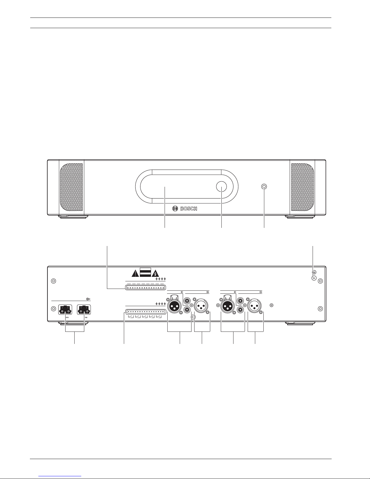
The DCN-CCUB2 Basic Central Control Unit controls the system. The basic central control unit
is a simplified version of the DCN-CCU2 Central Control Unit. The DCN-CCUB2 Basic Central
Control Unit:
– Has one XLR output.
– Does not have any XLR inputs.
– Does not have a fault contact.
– Cannot be connected to the optical network Controls, connectors and indicators.
The following sections give more information about the mentioned subject:
– Planning: Section 4 Planning.
– Installation: Section 5.1 19 inch units.
– Connection: Section 6.1 19 inch Units and Section 6.2 DCN-CCU2 and DCN-CCUB2 Central
Control Units.
– Configuration: Section 7.2 19 inch units and Section 7.3 DCN-CCU2 and DCN-CCUB2
Central Control Units.
– Operation: Section 8.2 DCN-CCU2 and DCN-CCUB2 Central Control Units.
– Troubleshooting: Section 9.2 DCN-CCU2 and DCN-CCUB2 Central Control Unit.
– Technical Data: Section 11.2.1 DCN-CCU2 and DCN-CCUB2 Central Control Units.
Conference System System Overview | en 17
Bosch Security Systems B.V. Installation and Operation manual DCN-NG_IOM_V4.1 | V1.3 | 2012.07
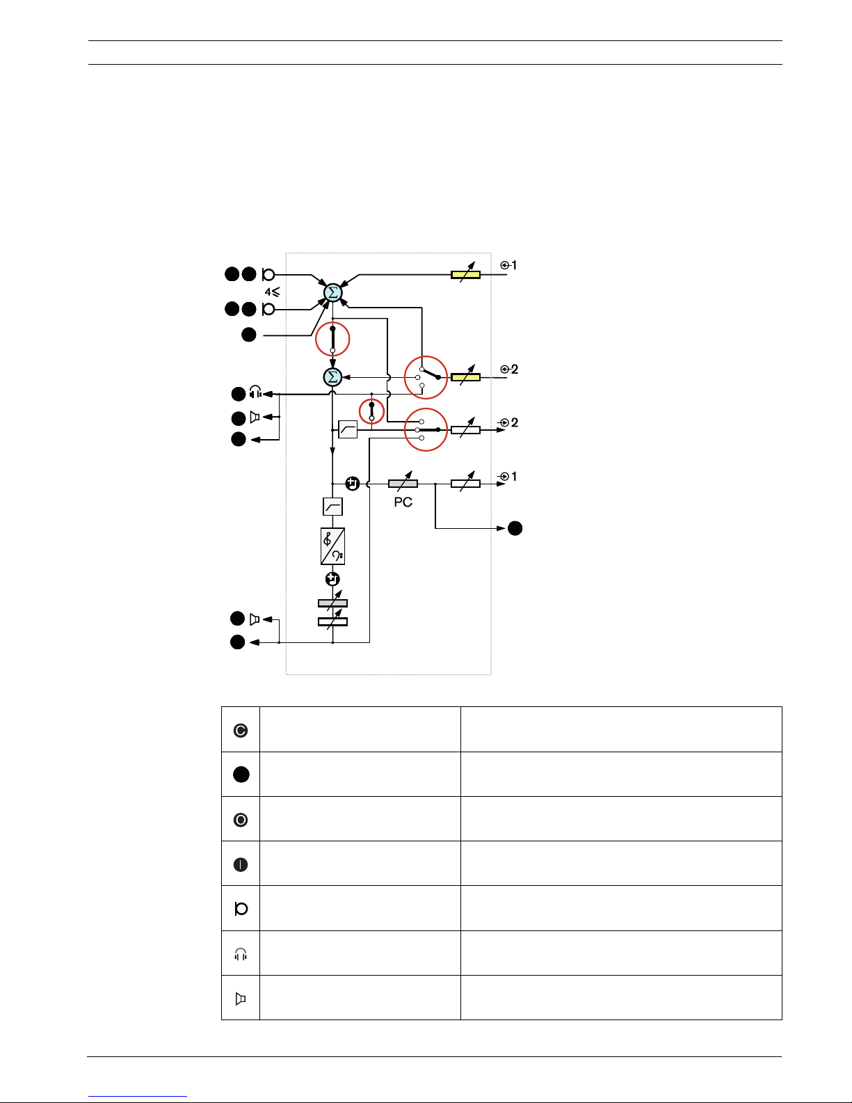
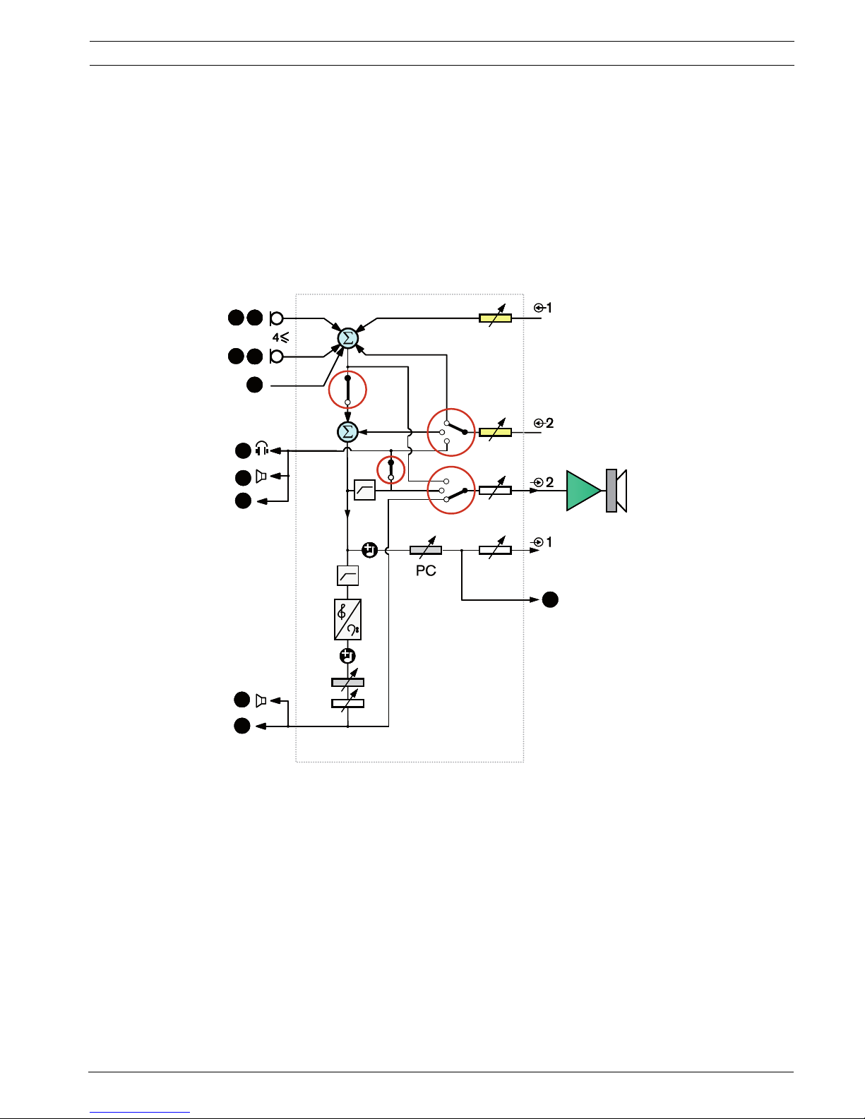
3.1.1 Audio I/O routing
Recorder
The Recorder mode is the default audio I/O routing mode. In the Recorder mode, audio output
2 of the central control unit transmits a signal that can be connected to an external audio
recorder. The central control unit has no effect on the volume level of the signal.
In the Recorder mode, the audio input 2 signal of the central control unit is added to the floor
signal.
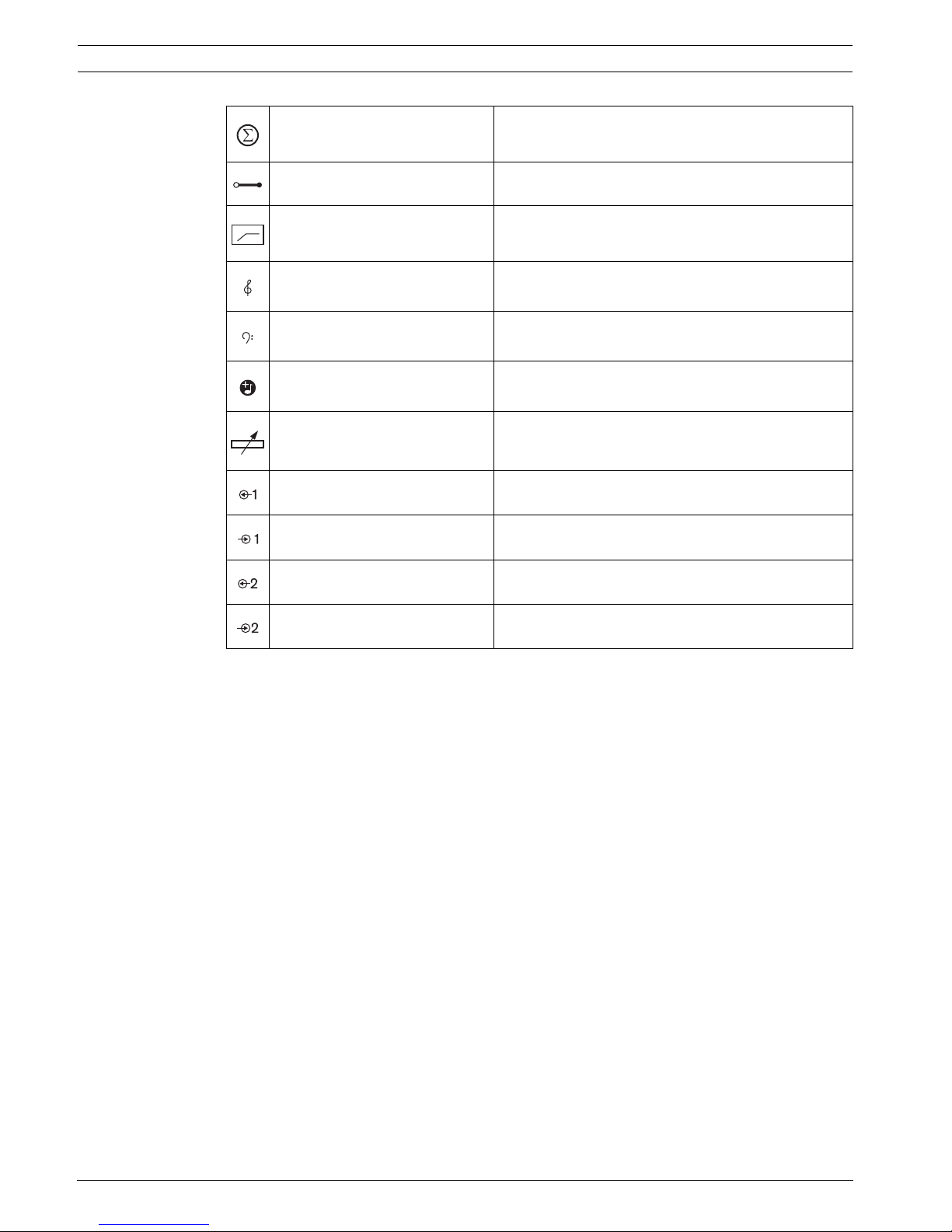
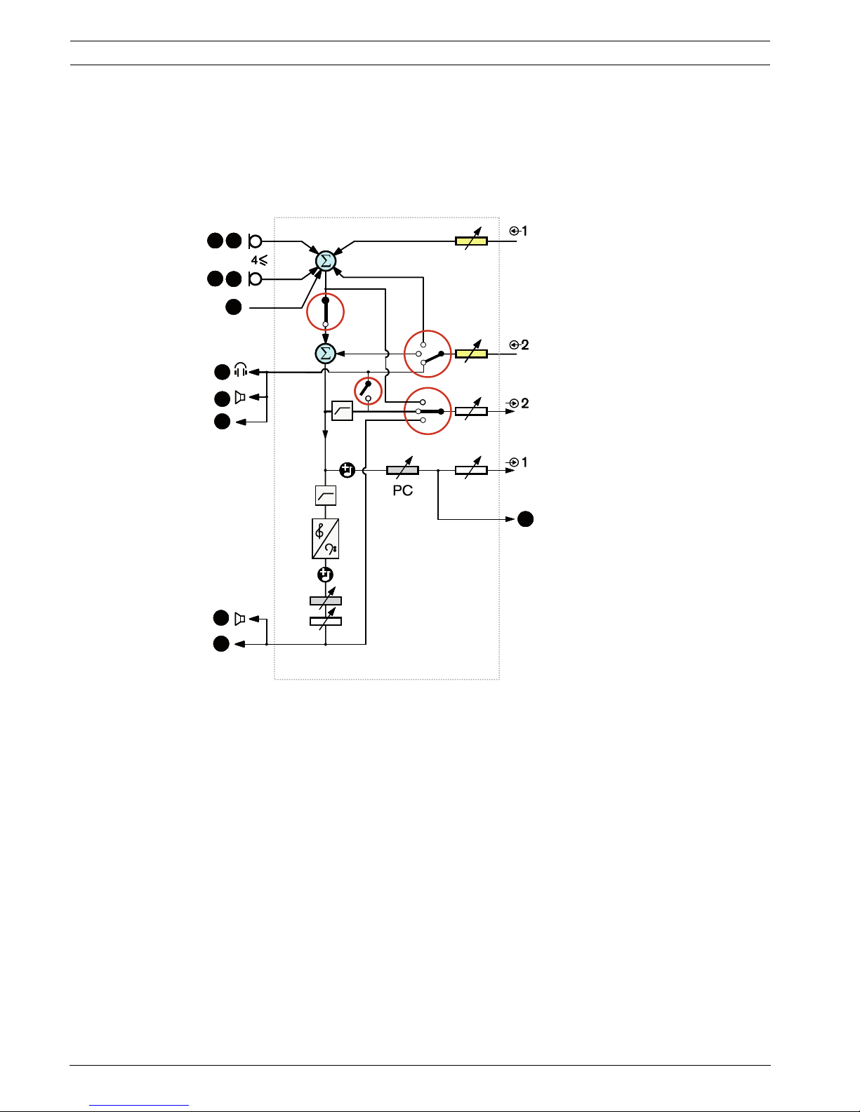
Figure 3.3 Audio processing scheme DCN-CCU2 or DCN-CCUB2
Contribution device(s) Wireless discussion units, wired discussion units,
Consentus units and/or flush mounted units.
Delegate Discussion unit microphones and loudspeakers.
Optical device(s) Central control units, audio expanders, Integrus
transmitter and/or wireless access point.
Interpretation device(s) Interpreter desk
Microphone --
Headphones --
Loudspeaker --
PC
CCU
DD
OO
cDcc
DD
cDcc
DD
OO
II
II
OO
OO
DDD
18 en | System Overview Conference System
DCN-NG_IOM_V4.1 | V1.3 | 2012.07 Installation and Operation manual Bosch Security Systems B.V.
Summation Summation of the signal
Switch --
Limiter --
Treble control --
Bass control --
Chime --
Level adjuster --
Audio input 1 Floor audio input
Audio output 1 Public Address audio output
Audio input 2 Selectable audio input
Audio output 2 Selectable audio output
Conference System System Overview | en 19
Bosch Security Systems B.V. Installation and Operation manual DCN-NG_IOM_V4.1 | V1.3 | 2012.07
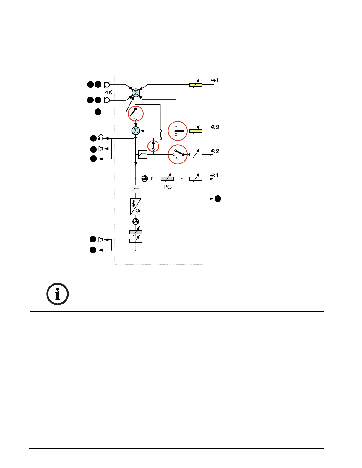
Delegate loudspeaker
In the Delegate loudspeaker mode, audio output 2 of the central control unit transmits a
signal that can be connected to an external public address system.
The central control unit sets:
– The volume signal level.
– The bass signal level.
– The treble signal level.
In the Delegate loudspeaker mode, the audio input 2 signal of the central control unit is added
to the floor signal.
Figure 3.4 Delegate loudspeaker
PC
CCU
DD
OO
cDcc
DD
cDcc
DD
OO
II
II
OO
OO
20 en | System Overview Conference System
DCN-NG_IOM_V4.1 | V1.3 | 2012.07 Installation and Operation manual Bosch Security Systems B.V.
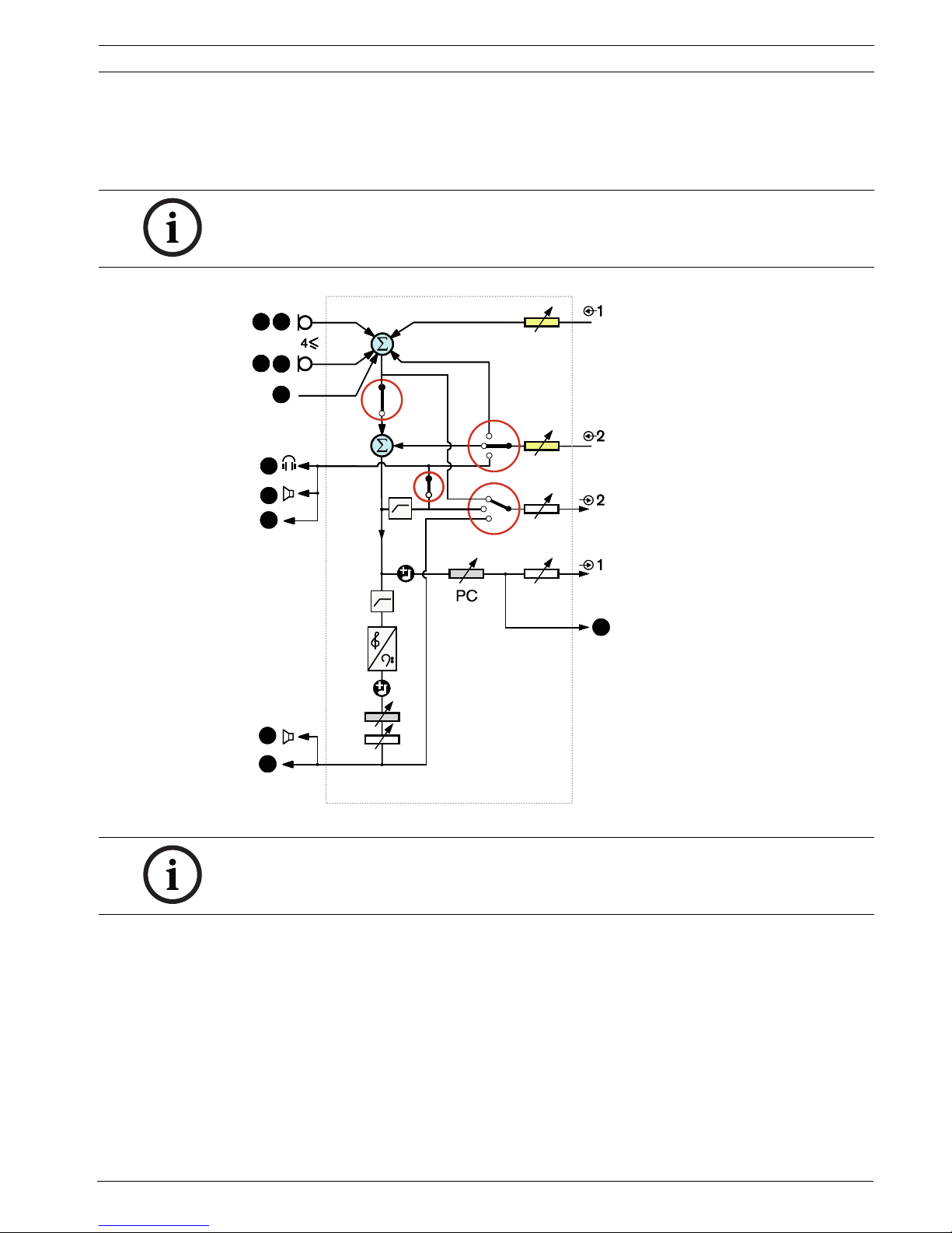
Insertion
In the Insertion mode, audio output 2 and audio input 2 of the central control unit are both
used to add signals from external audio devices. For example, connection of an external audio
mixer between audio output 2 and audio input 2 of the central control unit.
Figure 3.5 Insertion
PC
CCU
DD
OO
cDcc
DD
cDcc
DD
OO
II
II
OO
OO
NOTICE!
In the Insertion mode, a device between audio output 2 and audio input 2 of the central
control unit could be connected. When no device is connected, the audio signals from
contribution devices (floor) leave the system, but do not enter the system again.
Conference System System Overview | en 21
Bosch Security Systems B.V. Installation and Operation manual DCN-NG_IOM_V4.1 | V1.3 | 2012.07
Mix-minus
Use the Mix-minus mode to connect via audio input and audio output 2:
– A telephone coupler.
– Two systems.
Figure 3.6 Mix-minus
NOTICE!
The Mix-minus connection prevents acoustic feedback.
PC
CCU
DD
OO
cDcc
DD
cDcc
DD
OO
II
II
OO
OO
A
NOTICE!
Use a telephone coupler, in case of long distances between the two systems.
22 en | System Overview Conference System
DCN-NG_IOM_V4.1 | V1.3 | 2012.07 Installation and Operation manual Bosch Security Systems B.V.
Interpreter floor insertion
Interpreter Floor Insertion is used in applications where interpreters have video screens to
view the conference room. In case the video signal has latency, the floor audio for the
interpreters, can be delayed with an external device to lip-sync it with the video plus improve
S/N ratio for systems with external floor and DCN interpretation Integrus. The external device
should be connected to output 2 and input 2.
Figure 3.7 Interpreter floor insertion
Local floor in Multi-CCU sytems
Local floor is applicable only for slave CCUs and is used to create directional sound. In the
Local floor mode, audio output 2 of the central control unit only transmits the floor signal of
the units connected to the DCN-CCU2. In this way audio outputs 2 of the slave CCUs can be
connected to multiple external public address system.
PC
CCU
DD
OO
cDcc
DD
cDcc
DD
OO
II
II
OO
OO
Conference System System Overview | en 23
Bosch Security Systems B.V. Installation and Operation manual DCN-NG_IOM_V4.1 | V1.3 | 2012.07
3.2 LBB4402/00 Audio Expander
Use the LBB4402/00 Audio Expander if the system needs more than two analog audio inputs
or audio outputs.
Typically, the audio expander is used to:
– Connect external recording devices to the system.
– Send audio signals to external devices.
– Connect systems.
Figure 3.8 Front and rear views
The front panel contains:
1. Display - Shows the configuration menu.
2. Knob - Operates the configuration menu.
3. Headphones socket - Headphone connection.
The rear panel contains:
4. Control inputs - Connects the audio expander to external devices. Through the control
inputs, external devices can control the audio inputs and the audio outputs of the audio
expander.
5. Audio inputs - Connects the audio expander to external analog audio sources.
6. Audio outputs - Connects the audio expander to external analog audio devices.
7. Ground screw - Connects the audio expander to ground.
8. Optical network sockets - Connects the audio expander to the optical network.
9. Control outputs - Sends the condition of the audio expander to external devices.
1 2 3 4 5
123
Network
Control In
Audio In 3
12345678
C NC NO C NC NO C NC NO C NC NO C NC NO
12
48V
Audio Out 3 Audio In 4 Audio Out 4
Audio In 1 Audio Out 1 Audio In 2 Audio Out 2
Control Out
48V
Avis
Caution
Risk of electric shock.
Do not open.
Risk of electric shock.
Do not open.
4
6
85
5
6 5
6569
7
24 en | System Overview Conference System
DCN-NG_IOM_V4.1 | V1.3 | 2012.07 Installation and Operation manual Bosch Security Systems B.V.
The following sections give more information about the mentioned subject:
– Connection: Section 6.3 LBB4402/00 Audio Expander.
– Configuration: Section 7.4 LBB4402/00 Audio Expander.
– Operation: Section 8.3 LBB4402/00 Audio Expander.
– Troubleshooting: Section 9.8 LBB 4402/00 Audio Expander.
– Technical Data: Section 11.2.2 LBB4402/00 Audio Expander.
3.3 PRS-4DEX4 Digital Audio Expander
Use the PRS-4DEX4 Digital Audio Expander if the system needs digital audio inputs or
outputs. Typically, the digital audio expander is used to:
– Connect external recording devices to the system.
– Send audio signals to external devices.
– Connect systems.
Figure 3.9 Front and rear views
The front panel contains:
1. Display - Shows the configuration menu.
2. Knob - Operates the configuration menu.
3. Headphones socket - Headphones connection.
1 2 3 4 5
Network
Control In
1234567 8
C NC NO C NC NO C NC NO C NC NO C NC NO
12
48V
Control Out
48V
Avis
Caution
Risk of electric shock.
Do not open.
Risk of electric shock.
Do not open.
In 1
Out 1
AES/EBU-SPDIF
In 2
Out 2
AES/EBU-SPDIF
123
4
6898
97
5
Conference System System Overview | en 25
Bosch Security Systems B.V. Installation and Operation manual DCN-NG_IOM_V4.1 | V1.3 | 2012.07
The rear panel contains:
4. Control inputs - Connects the audio expander to external devices. Through the control
inputs, external devices can control the audio inputs and the audio outputs of the audio
expander.
5. Ground screw - Connects the digital audio expander to ground.
6. Optical network sockets - Connects the audio expander to the optical network.
7. Control outputs - Sends the condition of the audio expander to external devices.
8. Audio inputs - Connects the audio expander to external digital audio sources.
9. Audio outputs - Connects the audio expander to external digital audio devices.
The following sections give more information about the mentioned subject:
–Connection: Section 6.4 PRS-4DEX4 Digital Audio Expander.
– Configuration: Section 7.5 PRS-4DEX4 Digital Audio Expander.
– Operation: Section 8.4 PRS-4DEX4 Digital Audio Expander.
– Technical Data: Section 11.2.3 PRS-4DEX4 Digital Audio Expander.
3.4 LBB4404/00 Cobranet Interface
Use the LBB4404/00 Cobranet Interface to connect the system to a CobraNet network.
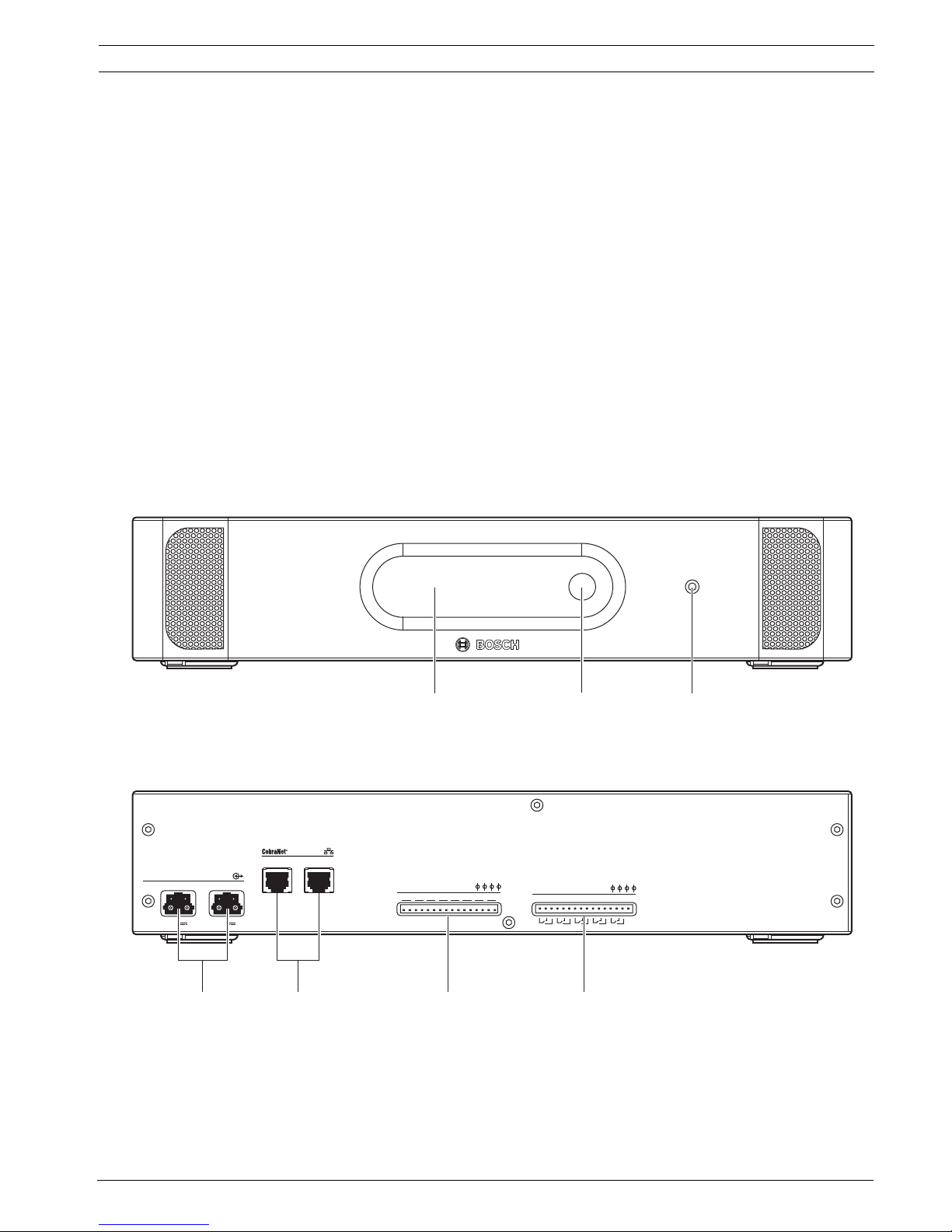
Figure 3.10 Front and rear views
The front panel contains:
1. Display - Shows the configuration menu.
2. Knob - Operates the configuration menu.
3. Headphones socket - Headphones connection.
Netw ork
Con t ro l In
1234567 8
C NC NO C NC NO C NC NO C NC NO C NC NO
12
48V
Con t ro l Ou t
1 2 3 4 5
48V
4675
2
1
3

26 en | System Overview Conference System
DCN-NG_IOM_V4.1 | V1.3 | 2012.07 Installation and Operation manual Bosch Security Systems B.V.
The rear panel contains:
4. Optical network sockets - Connects the cobranet interface to the optical network.
5. CobraNet sockets - Connects the cobranet interface to the CobraNet network. The
CobraNet network contains the audio inputs and the audio outputs of the cobranet
interface.
6. Control inputs - Connects the cobranet interface to external devices. Through the control
inputs, external devices can control the audio inputs and the audio outputs of the
cobranet interface.
7. Control outputs - Sends the condition of the cobranet interface to external devices.
The following sections give more information about the mentioned subject:
– Connection: Section 6.5 LBB4404/00 Cobranet Interface.
– Configuration: Section 7.6 LBB4404/00 Cobranet Interface.
– Operation: Section 8.5 LBB4404/00 Cobranet Interface.
– Technical Data: Section 11.2.4 LBB4404/00 Cobranet Interface.
Conference System System Overview | en 27
Bosch Security Systems B.V. Installation and Operation manual DCN-NG_IOM_V4.1 | V1.3 | 2012.07
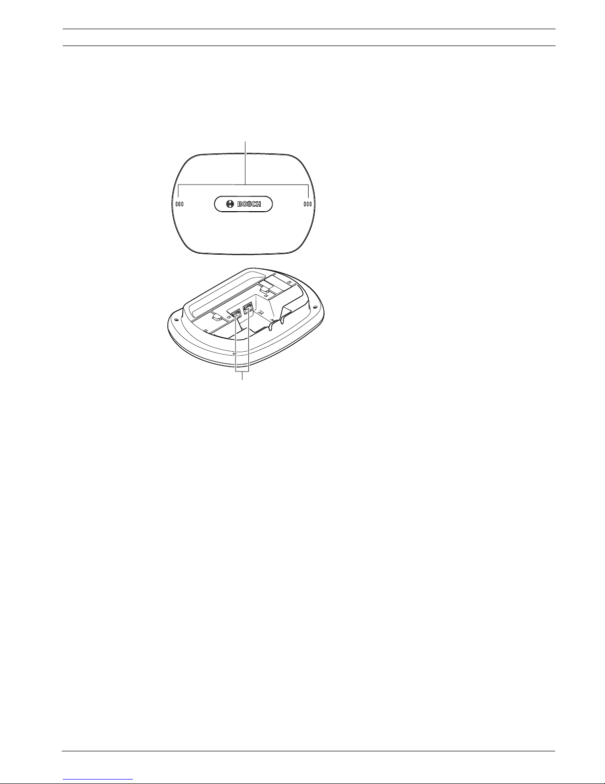
3.5 DCN-WAP Wireless Access Point
The wireless access point:
– Sends signals from the central control unit to the wireless devices.
– Receives signals from the wireless devices and sends them to the central control unit.
Figure 3.11 Top and bottom views
The wireless access point contains:
1. Status LEDs - Gives information about the condition of the wireless network and the
wireless access point.
2. Optical network sockets - Connects the wireless access point to the optical network.
The following sections give more information about the mentioned subject:
– Installation: Section 5.2 DCN-WAP Wireless Access Point.
–Connection: Section 6.6 DCN-WAP Wireless Access Point.
– Configuration: Section 7.9 DCN-WAP Wireless Access Point.
– Operation: Section 8.6 DCN-WAP Wireless Access Point.
– Troubleshooting: Section 9.9 DCN-WAP Wireless Access Point.
– Technical Data: Section 11.2.5 DCN-WAP Wireless Access Point.
1
2
28 en | System Overview Conference System
DCN-NG_IOM_V4.1 | V1.3 | 2012.07 Installation and Operation manual Bosch Security Systems B.V.
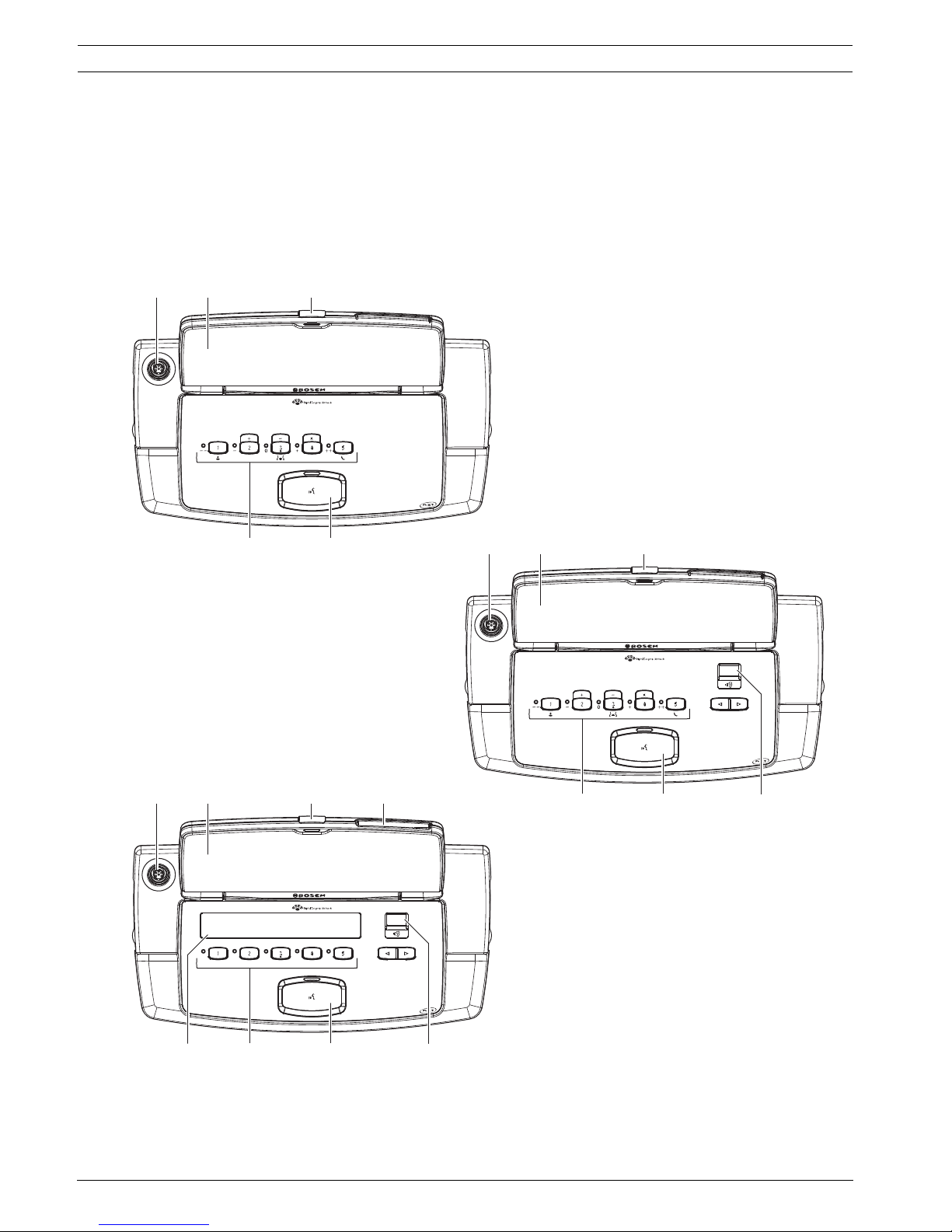
3.6 DCN-CON Concentus Units
With the Concentus Units (DCN-CON, DCN-CONCS and DCN-CONFF), the delegates can make
contributions to a conference.
With the Concentus Chairman Unit (DCN-CONCM), the chairman can monitor and control a
conference.
Figure 3.12 To p views
7 6
1
2 3
78 6 5
1
2 3 4
7 6 5
1
2 3
DCN-CON
DCN-CONFF
DCN-CONCS
Conference System System Overview | en 29
Bosch Security Systems B.V. Installation and Operation manual DCN-NG_IOM_V4.1 | V1.3 | 2012.07
The top of the Concentus delegate units contains:
1. Microphone socket - Connects a Pluggable Microphone (DCN-MICL or DCN-MICS) to the
Concentus delegate unit.
2. Loudspeaker - Gives the audio signal from the floor to the delegate. When the
microphone is enabled, the signal of the loudspeaker is muted.
3. Microphone LED - Is on when the microphone is enabled.
4. Card reader - Gives access to the Concentus delegate unit.
5. Channel selector - Selects the channel that is sent to the headphones.
6. Microphone button - Enables or disables the microphone. The microphone button has a
LED that shows the condition of the microphone.
7. Voting buttons - Operate the Concentus delegate unit. Each voting button has a yellow
LED. The LED shows the condition of the voting button.
8. Display - Shows the menu of the Concentus delegate unit.
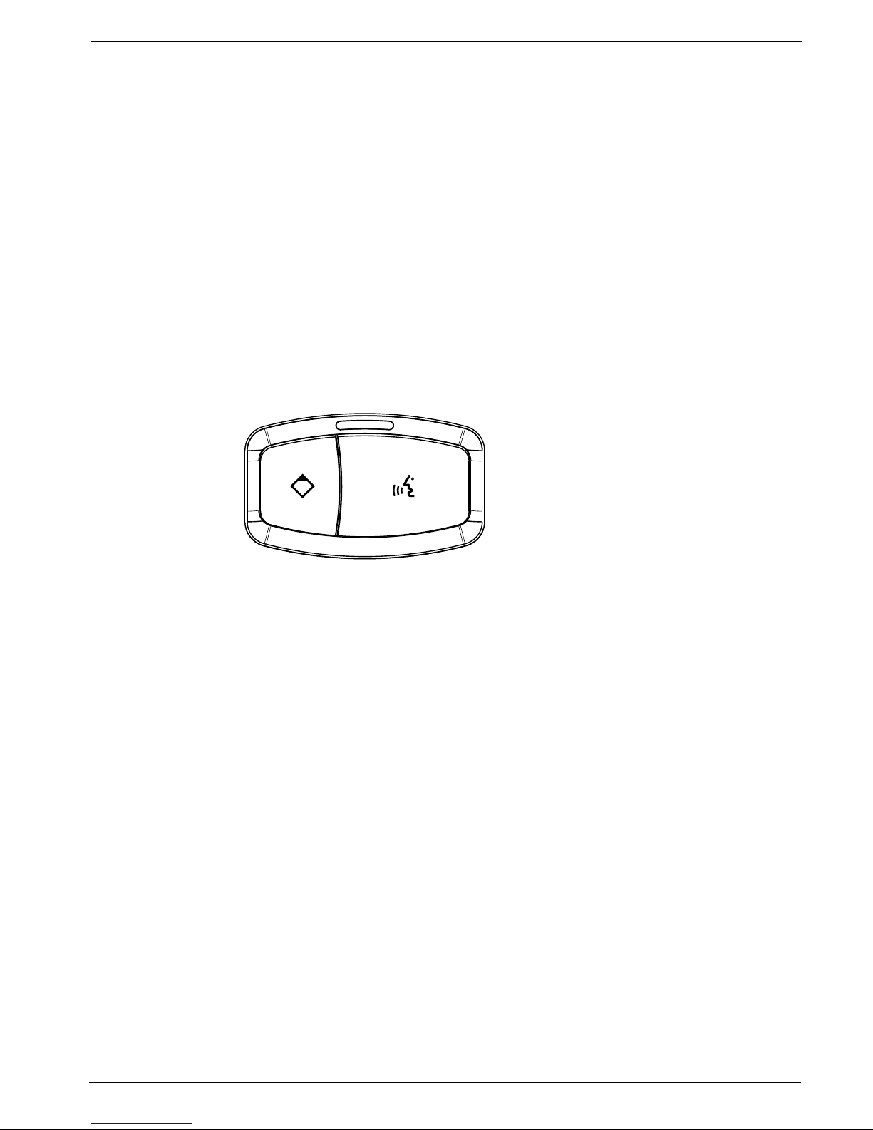
The only difference between the Concentus chairman unit and the Concentus delegate unit is
the priority button on the left of the microphone button.
Figure 3.13 Priority and microphone buttons
With the priority button, the chairman can disable the microphones of all delegate devices. At
the same time, the priority button enables the microphone of the chairman. The system has
the possibility to:
– Play an attention chime when the chairman pushes the priority button.
– Erase the request-to-speak list and the speakers list when the chairman pushes the
priority button.
30 en | System Overview Conference System
DCN-NG_IOM_V4.1 | V1.3 | 2012.07 Installation and Operation manual Bosch Security Systems B.V.
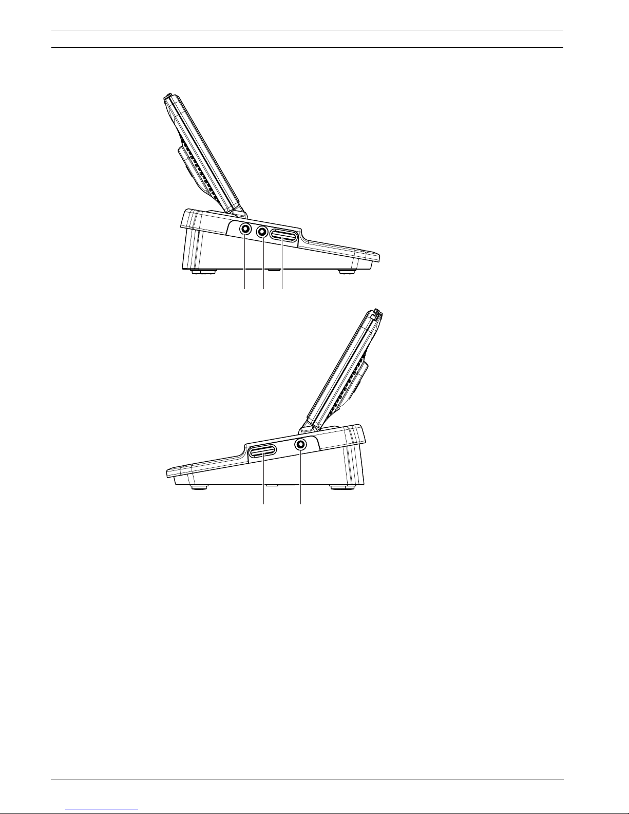
Figure 3.14 Side views
The left and right sides of the Concentus delegate units contains:
9. External microphone socket - Connects an external microphone or the microphone of a
headset to the left side of the Concentus delegate unit.
10. Headphones sockets - Headphone connection (on both sides).
11. Volume controls - Headphone volume level adjustment.
9 10 11
11 10
DCN-CONCS, DCN-CONFF
 Loading...