

Page 1

Control Panels
D9412GV4/D7412GV4 v2.00
en Installation and System Reference Guide
Page 2

D9412GV4/D7412GV4 v2.00 | Installation and System Reference Guide | Certifications and Approvals
.
equivalence number (REN). If requested, this
Certifications and Approvals
The D9412GV4/D7412GV4 v2.00 Literature Pack
includes an Approved Applications chapter in this
guide. Refer to this chapter for additional
guidelines on installing the control panels in
Underwriters Laboratories Inc. (UL) and firespecific applications.
Listings and Approvals
UL
The D9412GV4 and D7412GV4 are listed as UL
864 Commercial Fire control panels. The
D9412GV4 and D7412GV4 are also UL Listed for
Central Station, Local, Auxiliary, Proprietary, and
Household Fire Alarm, and Central Station, Local,
Police Station Connect, Holdup, Household
Burglar Alarm and Encrypted line Security when
communicating via a network.
cUL
The D9412GV4 and D7412GV4 are cUL listed for
Local Burglar Alarms, Signal Receiving Centre and
Premise Alarm, Residential Fire, Household
Burglar, Propriety Burglar, and Digital Apparatus.
Department of Defense (DOD)
The D9412GV4/D7412GV4 was granted approval
for Department of Defense (DoD) installations in
Sensitive Compartmented Information Facilities
(SCIF).
Federal Communications Commission
(FCC) Rules
Part 15
This equipment was tested and found to comply
with the limits for a Class B digital device,
pursuant to Part 15 of the FCC rules. These limits
are designed to provide reasonable protection
against harmful interference when the equipment
is operated in a commercial environment.
This equipment generates, uses, and can radiate
radio frequency energy; and if not installed and
used according to the instructions, can cause
harmful interference to radio communications.
Operation of this equipment in a residential area
is likely to cause harmful interference, in which
case the user is required to correct the
interference at his or her own expense.
Part 68
This equipment complies with Part 68 of FCC
rules. A label contains, among other information,
the FCC registration number and ringer
information must be provided to the telephone
company.
The D9412GV4 and D7412GV4 Control Panels are
registered for connection to the public telephone
network using an RJ38X or RJ31X jack.
The REN is used to determine the number of
devices that can be connected to the telephone
line. Excessive RENs on the telephone line may
result in the devices not ringing in response to an
incoming call. In most, but not all areas, the sum
of the RENs should not exceed five. To be certain
of the number of devices that may be connected
to the line, as determined by the RENs, contact
the telephone company to determine the
maximum REN for the calling area.
If you experience trouble with the control panel,
please contact Bosch Security Systems Customer
Service for repair and warranty information. If the
trouble is causing harm to the telephone
network, the telephone company might request
that the equipment be removed from the network
until the problem is resolved. User repairs must
not be made, and doing so will void the user’s
warranty.
If the D9412GV4, or D7412GV4 Control Panels
causes harm to the telephone network, the
telephone company attempts to notify you in
advance. If advance notice is not practical, the
telephone company notifies you as soon as
possible. Also, you will be advised of your right to
file a complaint with the FCC if you believe it is
necessary.
The telephone company might make changes in
its facilities, equipment, operations, or
procedures that could affect the operation of the
equipment. If this happens, the telephone
company provides advance notice in order for the
necessary modifications to be made, resulting in
uninterrupted service.
This equipment cannot be used on public coin
service provided by the telephone company.
Connection to Party Line service is subject to
state tariffs. (Contact your state public utilities
commission for information.)
FCC Registration Number:
US:ESVOT00BD9412GV3
Service Center in USA:
Bosch ST Service Center
8601 East Cornhusker Hwy
Dock B
Lincoln, NE 68507 - 9702 USA
Ringer Equivalence: 0.0B
Bosch Security Systems, Inc. | 2/13 | F01U265457-03 2
Page 3

D9412GV4/D7412GV4 v2.00 | Installation and System Reference Guide | Contents
.
Contents
Federal Communications Commission (FCC)
Rules ........................... 2
1.0 Introduction ...................... 7
2.0 Lightning Strikes .................. 9
2.1 Effects .......................... 9
2.2 Precautions during Installation ....... 9
3.0 Overview ....................... 10
3.1 Configuration and Parts ............ 10
3.1.1 Parts List ............................................... 11
3.1.2 Parts Available by Separate Order ......... 11
3.2 Accessories ..................... 12
3.3 Features in the GV4 Series Control Panels
............................... 13
3.3.1 SDI Interconnect Wiring ........................ 13
3.3.2 Tip and Ring Posts ................................. 13
3.3.3 Telephone Line Sniff .............................. 13
3.3.4 Points .................................................... 14
3.3.5 Areas and Accounts ............................... 14
3.3.6 Digital Communicator ............................ 14
3.3.7 Keypads ................................................. 14
3.3.8 Keyswitch .............................................. 15
3.3.9 Access Control ....................................... 15
3.3.10 Event Memory ........................................ 15
3.3.11 Event Log ............................................... 15
3.3.12 Ground Fault Detection ......................... 15
3.3.13 Ground Fault Detection Added Feature 15
3.3.14 Conettix Functions ................................ 16
3.3.15 Programming ......................................... 16
3.3.16 Dual Authentication ............................... 16
3.3.17 Other Features ...................................... 16
4.0 Installation ...................... 17
4.1 Installation Preparation ............ 17
4.2 Enclosure Options ................ 17
4.3 Mounting Enclosure ............... 17
4.4 Installing the Control Panel ......... 18
4.5 Connecting Earth Ground .......... 18
4.5.1 Terminal 10 ............................................ 18
4.5.2 Ground Fault Detect Enable .................. 18
4.5.3 Enabling Ground Fault Detection .......... 18
4.5.4 Ground Fault Specifications .................. 18
4.5.5 Locking the Reset Pin ............................ 19
4.6 Completing the Installation ......... 19
4.6.1 Charging the Battery .............................. 19
4.6.2 Installing and Wiring Detection Devices 19
4.6.3 Installing Modules and Outputs ............. 20
4.6.4 Connecting the On-board Points and
Keypads ................................................. 20
4.6.5 Powering Up .......................................... 20
4.7 Updating Control Panel Firmware .... 20
4.8 Programming the Control Panel ..... 20
4.9 Installing the Point Chart Label ...... 20
4.10 Testing the System ............... 20
4.11 Service Walk Test ................ 21
5.0 Power Supply .................... 24
5.1 Primary Power Terminals 1 and 2 .... 24
5.1.1 Primary (AC) Power Circuit ................... 24
5.1.2 Installing the Transformer ..................... 24
5.2 Secondary Power Terminals ........ 24
5.2.1 Secondary (DC) Power .......................... 24
5.2.2 Installing the Battery ............................. 25
5.2.3 Replacing the Battery ............................ 26
5.2.4 Battery Supervision ............................... 27
5.2.5 Battery Charging Circuit Float Charge .. 27
5.2.6 Battery Discharge and Recharge Schedule
.............................................................. 28
6.0 Power Outputs ................... 30
6.1 Circuit Protection ................ 30
6.2 Total Available Power ............. 30
6.3 Continuous Power Output Terminals 3, 8,
24, and 32 ...................... 30
6.4 Programmable Power Output Terminals 6,
7, and 8 ........................ 30
6.4.1 Programming ......................................... 31
6.4.2 Terminals 6 and 7 .................................. 31
6.4.3 Fire System Power Formula .................. 31
6.4.4 Terminal 8.............................................. 31
7.0 Telephone Connections ............ 32
7.1 Registration ..................... 32
7.2 Notification ..................... 32
7.3 Location........................ 32
7.4 Telephone Cord Connection ........ 32
7.5 Phone LED (Red) ................. 33
7.6 Operation Monitor LED (Green) ..... 33
7.7 Dialing Format ................... 33
7.8 Telephone Line Monitor ........... 33
7.9 Called Party Disconnect ........... 34
7.10 Communication Failure ............ 34
7.11 D928 Dual Phone Line Switcher ..... 34
7.11.1 Description ............................................ 34
7.11.2 Operation .............................................. 34
7.11.3 Installing the D928 ................................ 35
7.11.4 D928 Status LEDs ................................. 35
8.0 On-Board Points ................. 37
8.1 Terminals 11 to 22 Description ...... 37
8.2 Point Sensor Loops ............... 37
8.3 Point Parameters ................. 37
8.4 Point Response Time .............. 38
Bosch Security Systems, Inc. | 2/13 | F01U265457-03 3
Page 4

D9412GV4/D7412GV4 v2.00 | Installation and System Reference Guide | Contents
.
Wiring Information for Installations Using
8.5
the Rothenbuhler 5110/4001-42 High
Security Bell .................... 38
9.0 Off-Board Points ................. 41
9.1 Zonex Buses .................... 41
9.1.1 POPIT Modules ...................................... 41
9.1.2 POPEX Modules ..................................... 41
9.1.3 Missing Conditions ................................ 41
9.1.4 Control Panel Responses to Missing Point
Conditions ............................................. 41
9.2 D8125 and D9127 POPIT Modules ... 41
9.3 Installing the D8125 POPEX Module .. 43
9.3.1 Mounting ................................................ 43
9.3.2 Wiring the D8125 to the Control Panel . 43
9.3.3 Wiring POPITs to the Data Expansion
Loop ...................................................... 44
9.3.4 Wiring Data Expansion Loops to POPEX
Modules ................................................. 44
9.3.5 POPIT Sensor Loops .............................. 44
9.3.6 POPIT Module Point Assignments ......... 45
9.3.7 Program Record Sheet .......................... 45
9.3.8 POPIT Labels ......................................... 45
9.4 D8128D OctoPOPIT Module ........ 46
9.4.1 Description ............................................ 46
9.4.2 Listings .................................................. 46
9.4.3 Installation ............................................. 46
9.4.4 Setting the OctoPOPIT Switches ........... 47
9.4.5 Mounting OctoPOPITs ........................... 47
9.4.6 Wiring OctoPOPITs ................................ 48
9.4.7 OctoPOPIT Sensor Loops ...................... 52
9.5 Testing Off-Board Points ........... 53
9.6 SDI2 Octo-input Point Modules ...... 53
9.7 Extra Point Events ................ 53
10.0 Off-Board Outputs .................. 55
10.1 D8129 OctoRelay ................. 55
10.1.1 Configuring the D8129 OctoRelay ......... 57
10.1.2 Relay Outputs ........................................ 57
10.1.3 Installation ............................................. 57
10.1.4 Wiring Connections ............................... 57
10.2 D811 Arm Status Relay Module ...... 58
10.2.1 Relay Output .......................................... 58
10.2.2 Installation ............................................. 58
10.2.3 Wiring Connections ............................... 58
10.3 SDI2 Octo-output Relay Modules .... 58
11.0 Arming Devices ..................... 60
11.1 Description ..................... 60
11.2 SDI/SDI2 Bus Terminals 29 to 36 .... 60
11.2.1 Shortcuts and Custom Functions .......... 60
11.2.2 Assigning an Address for the Keypad .... 61
11.2.3 Installation ............................................. 61
11.3 D279A Independent Zone Control .... 62
11.4 Keyswitch ...................... 62
11.4.1 Description ............................................ 62
11.4.2 Programming ......................................... 62
11.4.3 Installation ............................................. 62
11.4.4 Operation .............................................. 62
12.0 SDI Devices ....................... 64
12.1 Description ..................... 64
12.2 Installation ...................... 64
12.2.1 Open Wire Trouble on SDI .................... 64
12.3 D9210C Access Control Interface Module
.............................. 64
12.3.1 Access ................................................... 64
12.3.2 Switch Settings ..................................... 64
12.4 SDI Addresses 88 and 92 .......... 65
12.4.1 Local RPS Programming ........................ 65
12.5 SDI Network Interface Modules ..... 65
12.5.1 Address Settings ................................... 66
12.5.2 Supervision ............................................ 66
13.0 SDI2 Devices ...................... 67
13.1 Description ..................... 67
13.2 Installation ...................... 67
13.2.1 Open Wire Trouble on SDI2 .................. 67
13.3 B208 Octo-input Module ........... 67
13.3.1 Address Settings ................................... 67
13.3.2 Supervision ............................................ 68
13.4 B308 Octo-output Module .......... 68
13.4.1 Address Settings ................................... 68
13.4.2 Supervision ............................................ 69
13.5 B426 Ethernet Communication Module 69
13.5.1 Address and Emulation Settings ........... 69
13.5.2 Supervision ............................................ 69
13.5.3 Local RPS Programming ........................ 69
13.5.4 Ethernet Communications Module Faults
.............................................................. 69
13.6 B420 Ethernet Communication Module 70
13.6.1 Address and Emulation Settings ........... 70
13.6.2 Supervision ............................................ 70
13.6.2 Local RPS Programming ........................ 70
13.6.3 Ethernet Communications Module Faults
.............................................................. 70
13.7 B520 Auxiliary Power Supply Module . 71
13.7.1 Address Settings ................................... 71
13.7.2 Supervision ............................................ 71
13.7.3 Auxiliary Power Supply Faults ............... 71
13.8 B810 wireless receiver ............ 72
13.8.1 Supervision ............................................ 72
13.8.2 Wireless Receiver Faults ........................ 72
13.8.3 Wireless Repeater Faults ........................ 72
13.9 B820 SDI2 Inovonics Interface Module 72
Bosch Security Systems, Inc. | 2/13 | F01U265457-03 4
Page 5

D9412GV4/D7412GV4 v2.00 | Installation and System Reference Guide | Contents
.
13.9.1
13.9.2 Wireless Receiver Faults ........................ 72
13.9.3 Wireless Repeater Faults ...................... 73
13.10 B920 Two-lined Alphanumeric Keypad 73
13.10.1 LCD Backlit Settings ............................. 73
13.10.2 LCD Power Up Status ........................... 73
13.10.3 LCD Communication Status ................. 73
13.11 B930 ATM Style Alphanumeric Keypad 73
13.11.1 LCD Backlit Settings ............................. 74
13.11.2 LCD Power Up Status ........................... 74
13.11.3 LCD Communication Status ................. 74
14.0 Installer Menu .... Error! Bookmark not
14.1 RPS Access Reports . Error! Bookmark
15.0 Accessory Connector ................ 75
16.0 Faceplates ........................ 76
16.1 D9412GV4/D7412GV4 v2.00 Faceplate 76
17.0 Specifications ...................... 77
17.1 Control Panel Power Supply ........ 77
17.2 B520 Power Supply ............... 78
17.3 Control panel Terminal Wiring ....... 79
18.0 Approved Applications ............... 81
18.1 Optional Compatible Equipment ..... 81
18.2 Burglary Applications .............. 81
18.3 Bank Safe and Vault Applications .... 81
18.3.1 Control Panel Enclosure Requirements . 81
18.3.2 Battery Connections .............................. 81
18.3.3 Bell Requirements ................................. 81
18.3.4 System Configuration Requirements ..... 81
18.3.5 Exit Delay ............................................... 82
18.3.6 Equipment Requirements ...................... 82
18.4 Fire Applications ................. 82
18.4.1 Four-Wire Smoke Detectors .................. 82
18.4.2 Two-Wire Smoke Detectors ................... 83
18.4.3 Two-Wire Smoke Detector Specifications
18.4.4 NFPA Style A (Class “B”) Circuit ............ 83
18.4.5 Other Devices ........................................ 83
18.4.6 UL Listed Two-Wire Smoke Detectors
18.4.7 UL Listed Synchronization (Sync)
18.5 Enclosures ...................... 91
18.5.1 D8103 Enclosure ................................... 91
18.5.2 D8108A Enclosure ................................. 91
18.5.3 D8109 Red Fire Enclosure ..................... 91
19.0 Keypad Installer Menu ............... 92
19.1 [1] Program Menu ................ 95
Supervision ............................................ 72
defined.
not defined.
............................................................... 83
Compatible with the D125B .................. 84
Modules and Strobes Compatible with the
D9412GV4/D7412GV4 ........................... 86
19.1.1 [1] Reporting > [1] Phone Menu
Parameters ............................................ 95
19.1.2 [1] Reporting > [2] Network Menu
Parameters ............................................ 96
19.1.3 [1] Reporting > [3] Routing Menu
Parameters ............................................ 99
19.1.4 [2] IP Module > [1] B42x (1) or [2] B42x
(2) Module Parameters ....................... 101
19.1.5 [2] IP Module > [1] B42x (1) or [2] B42x
(2) [2] Address Parameters ................ 102
19.1.6 [2] IP Module > [1] B42x (1) or [2] B42x
(2) [3] DNS Parameters ...................... 104
19.1.7 [3] RPS > [1] RPS Passcode Menu
Parameters .......................................... 105
19.1.8 [3] RPS > [2] RPS Phone Number Menu
Parameters .......................................... 106
19.1.9 [3] RPS > [3] RPS IP Address Menu
Parameters .......................................... 106
19.1.10 [3] RPS > [4] RPS Port Number Menu
Parameters .......................................... 107
19.1.11 [4] Area Options Menu Parameters ... 107
19.1.12 [5] Keypad > [1] Scope Menu Parameters
............................................................ 109
19.1.13 [6] Users Menu Parameters ............... 110
19.1.14 [7] Points Menu Parameters .............. 112
19.1.15 [8] Disable Programming Menu
Parameters .......................................... 119
19.2 [2] Wireless Menu ............... 120
19.2.1 [1] Points > [1] Enroll Point RFID Menu
Parameters .......................................... 120
19.2.2 [1] Points > [2] Replace Point RFID Menu
Parameters .......................................... 120
19.2.3 [1] Points > [3] Remove Point RFID Menu
Parameters .......................................... 121
19.2.4 [2] Repeaters > [1] Add Repeater Menu
Parameters .......................................... 121
19.2.5 [2] Repeaters > [2] Replace Repeater
19.2.6 [2] Repeaters > [2] Remove Repeater
19.2.7 [3] Diagnostics > [1] RF Points ............ 123
19.2.8 [3] Diagnostics > [2] RF Repeaters ...... 124
19.3 [3] Network Menu ............... 126
19.3.1 [1] B42x > [1] Settings Menu Parameters
19.4 [4] Srvc Byp Menu ............... 127
19.5 [5] Versions Menu ............... 127
20.0 UL/NFPA Compliant Installations ... 128
20.1 Required Components ............. 128
20.2 Installing Combination Fire and Intrusion
Menu Parameters ................................ 122
Menu Parameters ................................ 123
............................................................ 126
Alarm Systems .................. 128
Bosch Security Systems, Inc. | 2/13 | F01U265457-03 5
Page 6

D9412GV4/D7412GV4 v2.00 | Installation and System Reference Guide | Contents
.
20.2.1
20.2.2 Zonex Bus Devices ............................... 128
20.2.3 SDI2 Bus Devices ................................. 129
21.0 Compatible UL Listed Components.. 130
22.0 Current Ratings Charts .............. 131
22.1 D8125MUX ....................... 131
22.2 Standby Battery Calculations ........ 131
23.0 NFPA 72 Fire Alarm Applications ...... 134
23.1 Household Burglary and Commercial
23.2 Bank Safe and Vault .............. 134
23.3 Standby Battery Calculation ....... 134
23.4 Central Station or Local Systems ... 135
23.5 Remote Station or Auxiliary Systems 135
23.6 Household Fire Warning Equipment . 136
23.7 UL 609 ........................ 136
23.8 UL 365 ........................ 136
23.9 UL 636 ........................ 137
23.10 ULC S304 Requirements .......... 137
Appendix A: System Wiring Diagrams ....... 138
A.1 Power Supply Side System Wiring .. 138
A.2 Input Points and Peripheral Devices
A.3 SDI and Zonex Devices System Wiring 140
A.4 SDI2 Bus Wiring Recommendations . 143
Appendix B: Point Address Charts ......... 145
B.1 Zonex 1 Points .................. 145
B.2 SDI2 Points .................... 146
SDI Bus Devices ................................... 128
Burglary ....................... 134
Wiring Diagrams ................ 139
Figures
Figure 1: System Configuration ............ 10
Figure 2: Enclosure Mounting ............ 17
Figure 3: Enabling Ground Fault Detection . 18
Figure 4: Reset Pin .................... 19
Figure 5: Service Walk Test Flow Chart Example
............................ 23
Figure 6: Battery Terminals ............. 25
Figure 7: Non-Power-Limited Wiring ....... 26
Figure 8: Charging and Battery LEDs ...... 27
Figure 9: RJ31X/RJ38X Wiring (RJ31X shown)
............................ 32
Figure 10: Phone Connector, Phone LED, and
Operation Monitor LED Locations . 33
Figure 11: D928 Dual Phone Line Switcher .... 35
Figure 12: On-board Point Sensor Loop Wiring 37
Figure 13: Rothenbuhler 5110/4001-42 High
Security Bell Wiring Configuration 39
Figure 14: Wiring the Rothenbuhler 5110/4001-
42 High Security Bell to the Control
Panel ....................... 40
Figure 15: Connecting the D8125 POPEX to the
D9412GV4 Control Panel ....... 42
Figure 16: Connecting the D8125 POPEX to the
D7412GV4 Control Panel ....... 43
Figure 17: D8128D OctoPOPIT Layout ...... 46
Figure 18: Connecting D8128D OctoPOPITs to
the D9412GV4 ................ 49
Figure 19: Connecting D8128D OctoPOPITs to
the D7412GV4 ................ 50
Figure 20: Wiring Multiple D8128Ds Using
Figure 21: D8128D OctoPOPIT Sensor Loops 52
Figure 22: D8129 Connections to the D9412GV4
Figure 23: D8129 Connections to the D7412GV4
Figure 24: D811 Arm Status Relay Module Wiring
Figure 25: D811 Arm Status Relay Module Wiring
Figure 26: External Power to SDI2 Devices .. 62
Figure 27: Keyswitch Wiring .............. 63
Figure 28: DX4020 DIP Switch Settings ..... 66
Figure 29: B208 Switches Set to Address 9 .. 67
Figure 30: B308 Switches Set to Address 9 .. 68
Figure 31: B426 Switch Set to Address 1 ... 69
Figure 32: B420 Switch Set to Address 1 ... 70
Figure 33: B520 Switch Set to Address 2 ... 71
Figure 34: B810 Switch Set to Address 1 ... 72
Figure 35: B820 Switch Set to Address 1 ... 72
Figure 36: Accessory Connection on D9412GV4
Figure 37: D9412GV4/D7412GV4 v2.00 Faceplate
Figure 38: Keypad Installer menu tree ...... 94
Figure 39: D9412GV4/D7412GV4 v2.00 Power
Figure 40: D9412GV4/D7412GV4 v2.00 Input
Figure 41: D9412GV4 SDI and Zonex Devices
Figure 42: D7412GV4 SDI and Zonex Devices
Figure 43: D9412GV4/D7412GV4 SDI2 Devices
Figure 44: SDI2 Bus Wiring ............. 143
Interconnect Wiring ............ 52
........................... 56
........................... 56
to the D9412GV4 .............. 59
to the D7412GV4 .............. 59
and D7412GV4 ............... 75
........................... 76
Supply Side System Wiring (Power
and Phone) ................. 138
Points and Peripheral Devices System
Wiring ..................... 139
System Wiring ............... 140
System Wiring ............... 141
System Wiring ............... 142
Bosch Security Systems, Inc. | 2/13 | F01U265457-03 6
Page 7

D9412GV4/D7412GV4 v2.00 | Installation and System Reference Guide | 1.0 Introduction
.
1.0 Introduction
This manual addresses the operation and installation of the D9412GV4/D7412GV4 v2.00 Control
Panels. Throughout this guide, the words “control panel” refer to all control panels (D9412GV4 and
D7412GV4). Table 2 on page 11 provides an overview of the differences in the control panels.
To obtain any of the documents in Table 1, contact Bosch Security Systems, Inc.
Customer Service at (800) 289-0096 and request the documentation by its corresponding
part number.
Table 1: Related Documentation
Product Type Name of Documentation Part Number
Control Panels Control Panels (D9412GV4/D7412GV4 v2.00) Release Notes
Control Panels (D9412GV4/D7412GV4 v2.00) Installation and System Reference
Guide (this document)
UL Certificated Bank Safe and Vault Applications Technogram 73-07302-0003
Control Panels (D9412GV4/D7412GV4 v2.00) Program Entry Guide F01U265459
Control Panels (D9412GV4/D7412GV4 v2.00) UL Installation Guide F01U2654621
Control Panels (D9412GV4/D7412GV4 v2.00) Quick Reference Guide F01U2654631
Control Panels (D9412GV4/D7412GV4 v2.00) SIA Quick Reference Guide F01U2654661
Keypads D279A Operation and Installation Instructions 464585
Two-line Alphanumeric Keypad (B920) Installation Guide F01U2654504
ATM Style Alphanumeric Keypad (B930)Installation Guide F01U2654514
Control Panels (D9412GV4/D7412GV4 v2.00) Control Panel Owner’s Manual F01U2654521
Expansion
Devices
Octo-input Module (B208) Installation and Operation Guide F01U2654565
Octo-output Module (B308) Installation and Operation Guide F01U2654585
RADION receiver SD (B810) Reference Guide F01U2618395
SDI2 Inovonics Interface Module (B820) Installation Guide F01U2654605
Conettix Ethernet Communication Module (B420) Installation and Operation Guide F01U2152366
Conettix Ethernet Communication Module (B426) Installation and Operation Guide F01U2662266
Auxiliary Power Supply Module (B520) Installation and Operation Guide F01U2654455
D8128D Installation Guide F01U0705375
D8125MUX Operation and Installation Guide F01U0349735
ISW-D8125CW-V2 Installation and Operation Guide F01U1616915
D9210C Installation and Operation Guide F01U2152325
1
Shipped with the control panel. 2Located on the documentation CD shipped with the control panel. 3Located on
www.boschsecurity.com
documentation CD shipped with the module.
. 4Shipped with the keypad. 5These documents ship with the modules. 6Find these documents on the
F01U265461
F01U265457
1
2
2
Copyright
This document is the intellectual property of Bosch Security Systems, Inc. and is protected by copyright. All
rights reserved.
Trademarks
All hardware and software product names used in this document are likely to be registered trademarks and must
be treated accordingly.
Bosch Security Systems, Inc. | 2/13 | F01U265457-03 7
Page 8
D9412GV4/D7412GV4 v2.00 | Installation and System Reference Guide | 1.0 Introduction
.
Determine Bosch Security Systems, Inc. Product Manufacturing Date
Use the serial number located on the product label and refer to the Bosch Security Systems, Inc. web site at
http://www.boschsecurity.com/datecodes.
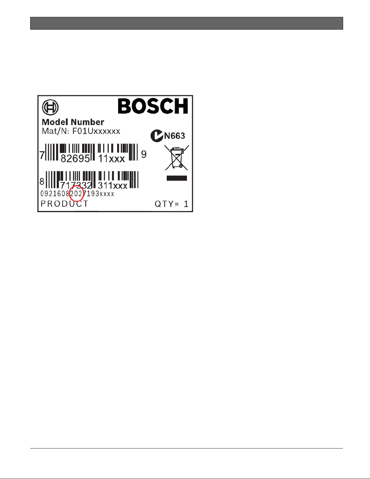
Thefollowingimageshowsanexampleofaproductlabelandhighlightswheretofindthemanufacturingdatewithintheserial
number.
Bosch Security Systems, Inc. | 2/13 | F01U265457-03 8
Page 9

D9412GV4/D7412GV4 v2.00 | Installation and System Reference Guide | 2.0 Lightning Strikes
.
2.0 Lightning Strikes
The control panels are designed to significantly
reduce electromagnetic interference and
malfunction generally caused by lightning.
2.1 Effects
Any electronic system can be struck directly by
lightning or be adversely affected by a lightning
strike near the system. When lightning strikes,
several things happen:
An electromagnetic wave spreads from
the point of the strike inducing high
voltages in nearby conductors.
The voltage changes substantially on
electrical grounds near the lightning
strike.
High voltages are induced in anything
directly struck by lightning.
The effects of a lightning strike can include
Missing Trouble, Missing Alarm, or Point Bus
Trouble events. Occasionally, Reboot and
Watchdog events might be sent because the
control panel tried to reset itself.
Electronic systems, including control panels,
cannot be completely immune to direct or
indirect lightning strikes; however, some proven
installation practices might greatly reduce the
risk of undesirable affects.
2.2 Precautions during Installation
To minimize the risk of undesirable effects from
lightning strikes on high risk installations that use
a point-bus technology:
Do not run wiring outside the building.
If you must install the unit in a metal
building, keep the wiring at least 0.61 m
(2 ft) away from external metal surfaces.
Earth ground the unit correctly. Do not
use an electrical ground or telephone
ground.
Avoid running wires near telephone, data,
or power lines inside a building. Historical
evidence shows that locating control
panel wiring at least 0.61 m (2 ft) away
from telephone, data, or power lines is
successful at minimizing lightning
damage. When your data lines must cross
the path of AC or other wiring, cross the
lines perpendicularly.
Bosch Security Systems, Inc. | 2/13 | F01U265457-03 9
Page 10
D9412GV4/D7412GV4 v2.00 | Installation and System Reference Guide | 3.0 Overview
.
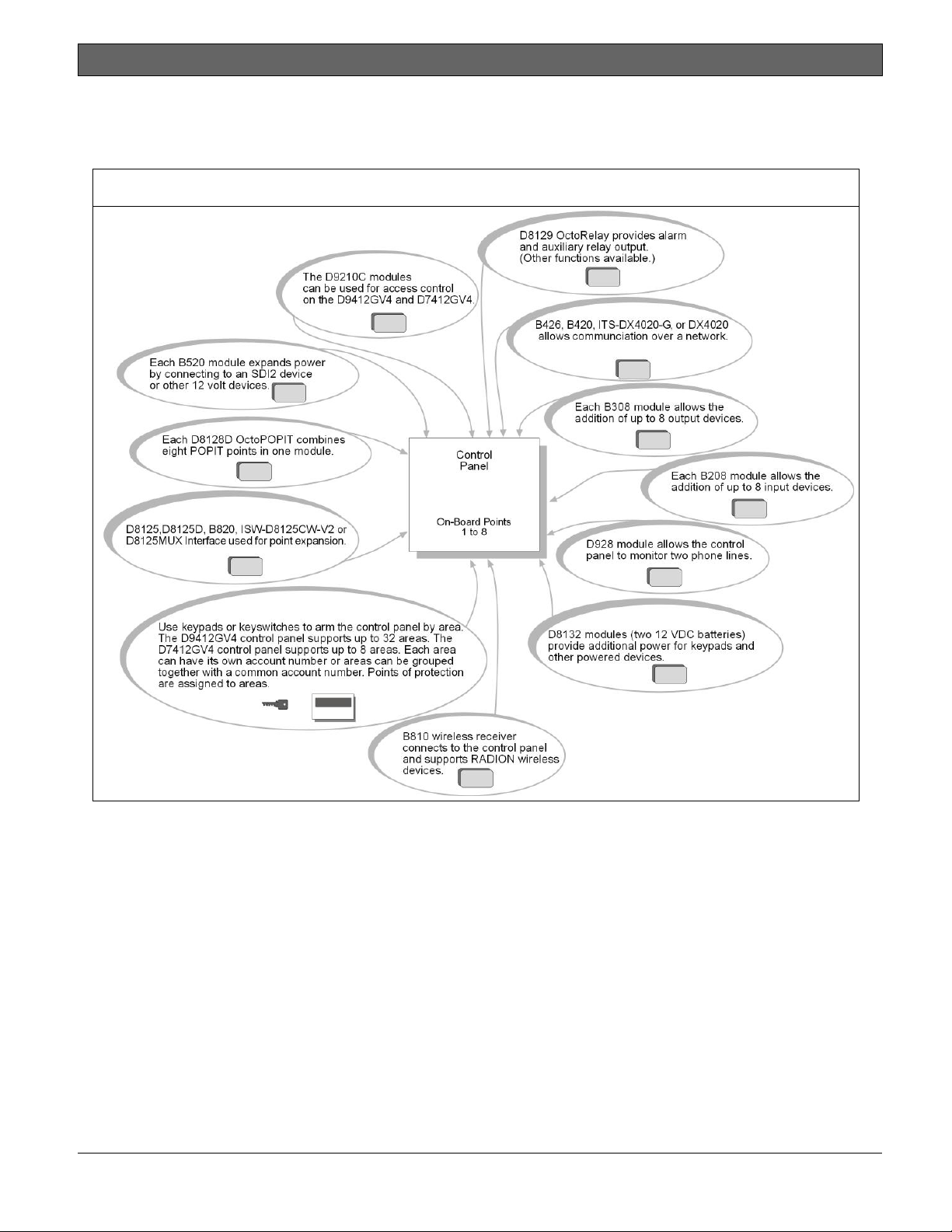
3.0 Overview
3.1 Configuration and Parts
Figure 1: System Configuration
Bosch Security Systems, Inc. | 2/13 | F01U265457-03 10
Page 11
D9412GV4/D7412GV4 v2.00 | Installation and System Reference Guide | 3.0 Overview
.
Table 2: Control Panel Comparrisons
Features D9412GV4 D7412GV4
Access Control
Arm/Disarm Users
Cards/Tokens
Passcode-Protected Custom Functions
Number of Points 246 75
Number of Off-board Relays 128 64
Number of Areas 32 8
Number of B920 Two-line Alphanumeric
Keypads
Number of B930 ATM Style
Alphanumeric Keypads
Number of D1255 Keypads 16 16
Number of D1260 Keypads 8 8
Number of Phone Lines Supported 2 2
Yes - 8 doors Yes - 2 doors
999 399
999 399
16 4
16 16
16 16
3.1.1 Parts List
The control panels are shipped assembled
from the factory with the following parts:
Literature Pack
7000/9000 Series Point Chart Label
(P/N: 79-06660-000)
Assembly
PC board
Faceplate shield
Mounting skirt
One #6 x 3/4-in screw
3.1.2 Parts Available by Separate Order
Order the following components separately to
complete a basic eight-point installation.
The D1260 and D1260B Keypads must
have firmware version 1.04 or higher
for use with the D9412GV4/D7412GV4
v2.00 Control Panels.
B520 Auxiliary Power Supply Module
B420, B426 Ethernet Communication
Modules
B920, B930 Keypad
D1255B, D1255, D1260, D1260B
Keypad, or D720 Keypad
D1255RB Fire Keypad, D1256RB Fire
Keypad, or D1257RB Fire Alarm
Annunciator
D1640 Transformer
D1640-CA Transformer (for Canada)
D126 or D1218 Battery
D162 Phone Cord (order two cords if
using the D928 Dual Phone Switcher)
D8103, D8108A, or D8109 Enclosure
Configured packages are also available. Please
consult the Bosch Security Systems, Inc.
Product Catalog.
Control Panels (D9412GV4/D7412GV4
v2.00) Installation and System Reference
Guide (P/N: F01U265457)
Bosch Security Systems, Inc. | 2/13 | F01U265457-03 11
Page 12

D9412GV4/D7412GV4 v2.00 | Installation and System Reference Guide | 3.0 Overview
.
3.2 Accessories
Refer to the Bosch Security Systems, Inc. product catalog for additional information.
The compatible accessories listed in the table below are specific to the D9412GV4/D7412GV4 with firmware
v2.00 or greater.
Table 3: Compatible Accessories
Model Title UL
B208 Octo-input Module X X X X
B308 Octo-output Module X X X X
B420 Ethernet Communication Module X X X X
B426 Ethernet Communication Module X X X X
B520 Auxiliary Power Supply Module X X X X
B810 RADION receiver SD X X
B820 SDI2 Inovonics Interface Module X X
B920 Two-line Alphanumeric Keypad X X X
B930 ATM Style Alphanumeric Keypad X X X
D113 Battery Lead Supervision Module X X X X
D122/D122L Dual Battery Harness X X X
D125B Powered Loop Interface Module X X X X
D126 Standby Battery (12V, 7Ah)
D129 Dual Class A Initiation Circuit Module X X X
D130 Relay Module X X X
D185 Reverse Polarity Module X X X
D161 Phone Cord
D162 Phone Cord
D192G Bell Circuit Supervision Module X X X
D279A Independent Zone Control (On-Board and OctoPOPIT
Points)
D720R LED Keypad (red) X X X
D720W LED Keypad (white) X X X
D928 Dual Phone Line Switcher X X X X
D1255RB Fire Keypad X X X X
D1256RB Fire Keypad X X X
D1257RB Fire Alarm Annunciator X X X X
D1218 12 V, 17.2 Ah Rechargeable Battery
D1255/D1255B Keypads (General Purpose) X X X
D1255W Text Keypad (white) X X X
D1260/D1260B2 Keypads X X X
D1640 16.5 VAC 40 VA Transformer X X X
D1640-CA 16.4 VAC 40 VA Transformer for Canada X
D8004 Transformer Enclosure X X X
D8125 POPEX Module X X X X
D8125MUX Multiplex Bus Interface X X X
D8128D OctoPOPIT Module X X X X
D8129 OctoRelay Module X X X X
D8130 Release Module X X X
D8132 Battery Charger Module X X X
D9127U/T POPIT Module X X X X
D9210C Access Control Interface Module X X X X
DX4010V2 USB/Serial Interface Module
1
Intrusion
UL
864
985
X
cUL
Intrusion
Bosch Security Systems, Inc. | 2/13 | F01U265457-03 12
Page 13
D9412GV4/D7412GV4 v2.00 | Installation and System Reference Guide | 3.0 Overview
.
DX4020 Network Interface Module X X X X
ITS-DX4020-G GPRS/GSM Communicator X X X
ICP-SDI-9114 SDI Splitter X X X
ITS-EZTS Tamper Switch X X X
ISW-D8125CW-V2 Commercial Wireless Interface Module
ZX776Z PIR Motion Sensor [15 m (50 ft)] with POPIT X
ZX794Z PIR Motion Sensor [24 m (80 ft)] with POPIT X
ZX865
ZX938Z PIR Motion Sensor [18 m (60 ft)] with POPIT X
ZX970
RFBT-A RADION speciality X
RFDL-11-A RADION tritech X
RFDW-SM-A RADION contact SM X
RFDW-RM-A RADION contact RM
RFSM-A RADION smoke X
RFRP-A RADION repeater X
RFPR-12-A RADION PIR
RFPR-C12-A RADION PIR C
RFUN-A RADION universal transmitter
1
Where the fire alarm transmitter is sharing on premise communications equipment, the shared equipment must be UL Listed
(ITE or fire protective signaling).
2
Refer to for compatible Inovonics devices.
3
Version 1.04 or above.
PIR/Microwave Motion Sensor [+1.7C (+35F)] with
POPIT
PIR/Microwave Motion Sensor [+1.7C (+35F)] with
POPIT
X
X
X
X
X
X
X
X
No wireless detectors have been
approved for use with alarm
verification points.
For specific installation and operation
instructions, please refer to
manufacturers’ manuals.
3.3 Features in the GV4 Series
Control Panels
3.3.1 SDI Interconnect Wiring
Use interconnect wiring to easily connect an
SDI bus device to the SDI bus or an SDI2
device to the SDI2 bus without needing to
disconnect wires connected to the bus
terminals. Possible applications include:
Connecting a DX4010v2 to program the
control panel with Remote
Programming Software (RPS) at the
premises.
Connecting a keypad to test the control
panel.
UL requires that the DX4010v2
be used as a temporary
programming interface only.
3.3.2 Tip and Ring Posts
The tip and ring posts allow connecting a
phone or buttset for the purpose of
troubleshooting communications between the
control panel and the central station. This
connection allows monitoring of the dial tone,
handshaking tones from the receiver, and
communications signals.
3.3.3 Telephone Line Sniff
The control panels monitor the phone line for
the programmed supervision interval before
indicating phone line trouble.
Bosch Security Systems, Inc. | 2/13 | F01U265457-03 13
Page 14

D9412GV4/D7412GV4 v2.00 | Installation and System Reference Guide | 3.0 Overview
.
3.3.4 Points
The Bosch Security Systems, Inc. D9412GV4
Control Panel provides up to 246 points of
protection. The D7412GV4 Control Panel
provides up to 75 points of protection. Point
programming parameters determine the
control panel’s response to open and shorted
conditions on the sensor loop for the point.
Several options allow individual point
programming to custom-fit the protection to
the installation.
Points 1 to 8 are located on the circuit board
(on-board points). They are standard sensor
loops. The remaining off-board points can be
located on point expansion modules on a
ZONEX bus, an SDI bus, and/or an SDI2 bus.
The ZONEX bus supports any combination of
POPIT points using D8128D OctoPOPITs,
D8125 POPEX Modules and D9127 POPITs, a
ISW-D8125CW-V2 Zonex Inovonics Interface
Module, or D8125MUX Modules. The SDI2 bus
supports any combination of B208 Octo-input
modules, B810 wireless receiver, or a B820
Inovonics Interface Module.
Any points programmed as fire
supervisory points are latching.
3.3.5 Areas and Accounts
The D9412GV4 supports up to 32 areas. The
D7412GV4 supports up to 8 areas. You can
assign all points to a single area or distribute
them over all supported areas.
The control panel is armed and disarmed by
area, and several areas can be armed and
disarmed with one menu function. A passcode
can also be assigned an authority level that
allows a user to arm an area from a remote
keypad in another area. Assigning each area its
own account number creates up to 32 separate
accounts in the D9412GV4 and up to 8
separate accounts in the D7412GV4. Assigning
the same account number to different areas,
groups them together in a single account.
Area options include exit tone and delay,
separate fire and burglary outputs, and
multiple opening and closing windows. Area
type can be used to create area
interdependencies for arming purposes.
3.3.6 Digital Communicator
The control panel uses a built-in digital
communicator to send reports to the receiver.
The control panel sends reports in either the
Modem4 or ANSI-SIA Contact ID format.
The control panel connects to an RJ31X or
RJ38X jack for telephone line seizure.
Connecting to the RJ31X complies with FCC
regulations for using the public telephone
network. The control panel can be
programmed to direct reports to four separate
telephone numbers. Adding the D928 Dual
Phone Line Switcher Module to the D9412GV4
or the D7412GV4 allows connection and
supervision of a second telephone line.
The system can route groups of Event Reports
to four different destinations through the
phone or over a network. Each report group
can be programmed to send reports to one or
more destinations. Primary and backup
reporting paths can be programmed for each
destination and each report group. A custom
option allows specification of individual Event
Reports to be sent.
3.3.7 Keypads
Up to 32 unsupervised keypads can be
connected to the system. The available power,
number of supervised keypads, and number of
areas covered affect the total number of
keypads that can be connected.
The system can supervise up to sixteen D1255
keypads, and up to eight D1260 keypads. If the
control panel loses communication with the
keypad, it sends SDI FAILURE in the Modem4
format or Expansion Module Failure (333) in
Contact ID format. The system can support
more SDI keypads (up to 32 unsupervised).
In addition to the SDI keypads, the system can
support up to 16 B920 and B930 keypads on
the SDI2 bus. The control panel supervises all
keypads on the SDI2 bus. Any failure to receive
an expected response from an SDI2 keypad
results in a system fault display on all keypads
and an SDI Fault event is sent to the central
station if programmed to do so.
Table 4 on page 15 shows the keypads that are
compatible with D9412GV4/D7412GV4 v2.00
Control Panels. Refer to 18.0 Keypad Installer
Menu for complete details on programming
keypad options.
Bosch Security Systems, Inc. | 2/13 | F01U265457-03 14
Page 15
D9412GV4/D7412GV4 v2.00 | Installation and System Reference Guide | 3.0 Overview
.
UL requires all Fire System keypads to
be supervised.
Table 4: Compatible Keypads
Model Display Application
B930 5-line LCD display Burglary/Access
B920 2-line LCD display Burglary/Access
D1255RB
D1256RB
D1257RB
D1255/
D1255B/
D1260/
D1260B
D1265* LCD Touch screen Burglary
*D1265 keypad has not been investigated by UL.
16-character
alphanumeric
16-character
alphanumeric
16-character
alphanumeric
16-character
alphanumeric
4-line by 20character
Fire
Fire
Fire
Burglary
Burglary
3.3.8 Keyswitch
Maintained or momentary closure devices such
as keyswitches allow any of the available areas
to be armed or disarmed. Point programming
determines the loop response and which area
a keyswitch controls.
3.3.9 Access Control
The D9412GV4 can control eight access doors
(each requiring the optional D9210C Access
Control Interface Module) with up to 999
uniquely identified cards or tokens. The
D7412GV4 can control two access doors with
up to 399 uniquely identified cards or tokens.
Any of the following can grant access:
Wiegand-style access control device
(card reader) connected to the D9210C
Access Control Interface Module
Request to enter (RTE) or request to
exit (REX) input
Unlock command on a B920/B930
The access control features of the D9412GV4
and D7412GV4 can deny access during armed
periods. The control panel can also grant
access only to certain authorized users
depending on whether the area is all on, part
on, or off. Programming for automatic
disarming when designated authorized users
are granted access is also possible.
The Dual Authentication feature can optionally
require passcode entry with presentation of
door credentials before access authorization is
granted.
3.3.10 Event Memory
The control panel retains point alarm and
trouble events in memory for each area. A
B930, B920, D1255 (any model), as well as a
D1260 (any model) can be used to view event
memory by using the Events menu. The control
panel clears the previous events for an area
from the event memory when the area is
turned off.
3.3.11 Event Log
The system stores 1023 events from all areas
in its event log. For example, the system adds
at least two items to the log each time an area
is turned on (arm) or off (disarm), the open (or
close) event also contains the previous arming
state.
All events can be stored even if the control
panel does not send a report for them. The log
can be viewed at a keypad, or uploaded using
Remote Programming Software (RPS).
3.3.12 Ground Fault Detection
The Earth Ground Terminal on the control
panels is electrically isolated from all other
terminals to allow the control panels to detect
ground fault conditions. A Ground Fault Detect
Enable switch (S4) is located just under
Terminal 10, Earth Ground, on the control
panel. Refer to Section 4.5.2 Ground Fault
Detect Enable on page 18 for information on
operating this function.
3.3.13 Ground Fault Detection Added Feature
When Ground Fault Detect is enabled (S4
closed), Points can be used for non-powered
fire-initiating devices such as heat detectors,
four-wire smoke detectors, and pull stations. A
D125B Powered Loop Interface or a D129 Dual
Class A Interface Module is not required when
connecting the non-powered fire-initiating
devices to Points.
Bosch Security Systems, Inc. | 2/13 | F01U265457-03 15
Page 16

D9412GV4/D7412GV4 v2.00 | Installation and System Reference Guide | 3.0 Overview
.
3.3.14 Conettix Functions
The D6600/D6100i/D6100IPV6 Conettix
System supports data network
communications. Conettix allows the
D6600/D6100i/D6100IPV6 Receiver/Gateway
devices to connect to various network
technologies including Ethernet, UDP/IP, and
GPRS (General Packet Radio System).
Connecting to a data network is possible using
the COM4 or COM1 connection from the
D6600/D6100i Receiver to the D6680 Network
Adapter. Control panels can send reports
through telephone lines, Ethernet, UDP/IP, or
GPRS networks to the
D6600/D6100i/D6100IPV6 receiver to the
central station. Once events are received, they
can then be issued to automation software or a
network printer through a local area network
(LAN) or wide area network (WAN).
Sending events to the central station over a
LAN or WAN requires a network interface
module (NIM), such as the B426, B420, or
DX4020. Sending events over GPRS requires a
special NIM, the ITS-DX4020-G.
3.3.15 Programming
Use the RPS, or the Keypad Installer menu, to
program the control panels. Refer to the
Control Panels (D9412GV4/D7412GV4 v2.00)
Program Entry Guide (P/N: F01U265459)for
programming options.
3.3.16 Dual Authentication
The D9412GV4 and D7412GV4 control panels
can be configured to require two forms of
identification before processing certain system
commands. This feature requires a door
controller and a keypad to be installed within
proximity to each other for user convenience.
Dual Authentication requires a
D9210C door controller module even
though the configured operation may
not be access.
A standard system user has authority to use
Dual Authentication if they have a passcode, a
door credential (token or card), and
appropriate command authority permissions
assigned in the door and keypads assigned
area. When enabled at a keypad, only the
following Passcode Functions require access
credentials with passcode entry, Arm / Disarm,
Cycle Door (Grant Access), Cycle Relay, and
Auto Re-arm. Refer to the Control Panels
(D9412GV4/D7412GV4 v2.00) Program Entry
Guide (P/N: F01U265459)and D9210C
Installation and Operation Guide (P/N:
F01U215232) for details on installation,
configuration and operation of this feature.
3.3.17 Other Features
The D9412GV4/D7412GV4 v2.00 Control
Panels have many programmable features.
Some of the features are listed below.
Complete details on all features are in the
Control Panels (D9412GV4/D7412GV4 v2.00)
Program Entry Guide (P/N: F01U265459):
Supervision of AC (primary power),
battery (secondary power), Zonex, SDI
and SDI2 buses, central processing unit
(CPU), and two telephone lines
Automatic System Test Reports
Remote access for programming,
diagnostics, and log uploads using the
remote programming software (RPS)
Fire alarm verification
Programmable alarm outputs
Programmable relay outputs
Opening and closing windows
Skeds (scheduled events)
Limited local programming
Bosch Security Systems, Inc. | 2/13 | F01U265457-03 16
Page 17
D9412GV4/D7412GV4 v2.00 | Installation and System Reference Guide | 4.0 Installation
.
4.0 Installation
4.1 Installation Preparation
This section contains a general installation
procedure and refers to other sections of the
document for detailed instructions.
Review this document and the Control Panels
(D9412GV4/D7412GV4 v2.00) Program Entry
Guide (P/N: F01U265459)before beginning the
installation to determine the hardware and wiring
requirements for the features used.
Have the following documentation available when
reading through this guide:
Control Panels (D9412GV4/D7412GV4
v2.00) Control Panel Owner’s Manual.
Before installation, become familiar with the
operation of RPS or the local Programmers menu.
4.2 Enclosure Options
Mount the control panel assembly in any of the
Bosch Security Systems, Inc. enclosures listed:
D8103 Universal Enclosure (tan)
D8109 Fire Enclosure (red)
D8108A Attack Resistant Enclosure (tan)
Refer to chapter 17.0 Approved Applications in
this guide to determine if the application requires
a specific enclosure.
4.3 Mounting Enclosure
1. Run the necessary wiring throughout the
premises.
2. Mount the enclosure in the desired location.
Use all five enclosure mounting holes. Refer
to Figure 2.
3. Pull the wires into the enclosure.
Electromagnetic interference (EMI)
can cause problems on long wire runs.
Figure 2: Enclosure Mounting
1
2
1 - Point chart label
2 - Mounting skirt hooks (2)
3 - Module mounting holes (12)
4 - Tamper switch mounting holes (5)
5 - Skirt mounting hole (1)
3
5
6
2
4
7
3
8
9
6 - Enclosure mounting holes (5)
7 - Mounting skirt hook holes (2)
8 - Back of D9412GV4/D7412GV4 Control Panel
9 - Lock down tab
Bosch Security Systems, Inc. | 2/13 | F01U265457-03 17
Page 18
D9412GV4/D7412GV4 v2.00 | Installation and System Reference Guide | 4.0 Installation
.
4.4 Installing the Control Panel
1. Place the control panel over the inside back
of the enclosure, aligning the large
rectangular openings of the mounting skirt
with the mounting hooks of the enclosure.
Slide the control panel down so that it hangs
on the hooks. Refer to Figure 2, Item 2 on
page 17.
2. Remove the tape from the #6 x 1/4-in screw
in the mounting tab on the control panel. The
screw passes through the mounting tab and
into the skirt mounting hole in the enclosure.
Tighten the screw to secure the control panel
in the enclosure.
3. Connect earth ground to the control panel
before making any other connections. Refer
to Section 4.5 Connecting Earth Ground.
4.5 Connecting Earth Ground
4.5.1 Terminal 10
When the control panel recognizes that the
ground fault condition is corrected, and remains
corrected for between 5 to 45 consecutive sec, a
Restoral Report is sent.
The D9412GV4 and D7412GV4 control
panels log and print a Ground Fault
event as GROUND FAULT. If
communicating in Modem4 format. If
communicating in Contact ID format,
the control panels generate a Ground
Fault (310) event.
4.5.3 Enabling Ground Fault Detection
To enable Ground Fault Detect Enable, lock
(close) the S4 Ground Fault Detect Pin on the
control panel (Figure 3).
Figure 3: Enabling Ground Fault Detection
10
To help prevent damage from electrostatic
charges or other transient electrical surges,
connect the system to earth ground at Terminal
10 before making other connections.
Recommended earth ground references are a
grounding rod or a cold water pipe.
Caution: Do not use telephone or
electrical ground for the earth ground
connection. Use 14 AWG (1.8 mm) to
16 AWG (1.5 mm) wire when making
the connection.
Do not connect other control panel
terminals to earth ground.
4.5.2 Ground Fault Detect Enable
To meet UL 864 requirements, enable
Ground Fault Detect.
A ground fault is a circuit impedance to earth
ground. The control panel has a ground fault
detection circuit that, when enabled, detects
ground faults on Terminals 1 to 9 and 11 to 32.
The control panel also detects and annunciates
ground faults on any device connected to it.
If a ground fault condition occurs, the keypads
display SERVC GND FAULT and the control panel
transmits a GROUND FAULT TROUBLE, AREA 1.
1 - S4 Locked (Closed). Control panel detects
ground faults.
2 - S4 Unlocked (Open). Control panel does not
detect ground faults.
4.5.4 Ground Fault Specifications
Table 5 provides the impedance specifications for
detecting ground faults when any terminal or
field wiring is shorted to ground.
Bosch Security Systems, Inc. | 2/13 | F01U265457-03 18
Page 19
.
D9412GV4/D7412GV4 v2.00 | Installation and System Reference Guide | 4.0 Installation
Table 5: Ground Fault Impedance
Specifications
Impedance Control Panel Detects Ground Fault
≤ 300 Ω Yes
300 Ω to
200 k Ω
≥ 200 k Ω No
Detection depends upon the
terminal
4.5.5 Locking the Reset Pin
Locking the reset pin disables the control panel
(Figure 4). When the control panel is disabled,
the system ignores most keypad commands and
points. Call for Service appears in some keypad
displays when the pin is locked down. SDI2
keypads display “Installation Passcode” when the
pin is locked down.
On-board outputs (Terminals 6 and 7) and offboard outputs deactivate when the control panel
is reset. Terminal 8 has power when the output is
deactivated. Activation interrupts power at that
terminal. The on-board output (Terminal 8)
remains deactivated when the reset pin is locked
in the disable position.
Releasing the reset pin from the closed position
resets the control panel. The control panel resets
all its timers, counters, indexes, and buffers. Any
points that restore after a reset do not generate
Restoral Reports.
If the reset pin is placed in the Lock position and
all areas are armed, the control panel will not
answer RPS over a phone line unless Answer
Armed program item has a value other than zero
in it. No entry is required for network or RPS
Enhanced direct connect communication. Refer
to RPS Parameters in RPS Help.
Figure 4: Reset Pin
1 - Reset pin locked (closed)
2 - Reset pin normal (open)
4.6 Completing the Installation
If not already complete, make the earth ground
connection to Terminal 10 and lock the reset pin
in the closed position.
4.6.1 Charging the Battery
Connect the battery, then the transformer to
allow the control panel to charge the battery
while you complete the installation. Refer to
Section 5.0 Power Supply on page 24 for
instructions.
On-board Buzzer Sounds at Power Up and Reset:
The system performs a series of self-diagnostic
tests of hardware, software, and programming at
power up and at reset. The buzzer on the control
panel sounds during the tests. The selfdiagnostics tests complete in approximately 1 to
3 sec.
If the control panel fails any test, the buzzer
continues sounding and a System Trouble
message appears at the keypads.
Avoid electrostatic discharge. Always
touch Terminal 10, the earth ground
connection, before beginning work on
the control panel.
If the control panel receives an electrostatic
discharge, it might generate Watchdog Reset and
Param Fail events.
4.6.2 Installing and Wiring Detection Devices
Install and wire detection devices and keypads at
their locations throughout the premises. Do not
connect the control panel yet.
Bosch Security Systems, Inc. | 2/13 | F01U265457-03 19
Page 20
D9412GV4/D7412GV4 v2.00 | Installation and System Reference Guide | 4.0 Installation
.
Section 8.0 On-Board Points on page 37
contains instructions for wiring the on-board
points to detection devices. Section 11.0 Arming
Devices on page 60 contains instructions for
wiring the keypads.
Instructions for wiring the off-board point POPIT
sensor loops are found in the instructions
packaged with the POPIT modules.
4.6.3 Installing Modules and Outputs
1. Power down the unit by unplugging the
transformer and disconnecting the battery.
Always power down the unit when
installing modules or outputs, or when
2. Install and wire any modules required for the
3. If using the power outputs at Terminals 7 or
4.6.4 Connecting the On-board Points and
Connect the on-board points and keypad wiring
to the system. Refer to Section 8.0 On-Board
Points on page 37 and Section 11.0 Arming
Devices on page 60 for instructions.
4.6.5 Powering Up
Reconnect the battery, then plug in the
transformer. The buzzer sounds for two sec when
the control panel is powered up. Leave the reset
pin in the locked position.
making wiring connections to the
control panel.
installation as described in the module’s
installation instructions.
Instructions for the D8125 POPEX Module,
D8128D OctoPOPIT Module, D8129
OctoRelay Module, D811 Arm Status Relay
Module, and D928 Dual Phone Line Switcher
appear in this guide.
Refer to Section Off-Board Points on page 41
for D8125 and D8128D instructions. Refer to
Off-Board Outputs on page 55 for D8129 and
D811 instructions. Refer to Section 7.11
D928 Dual Phone Line Switcher on page 34
for D928 instructions.
8, refer to Section Programmable Power
Output Terminals 6, 7, and 8 on page 30 for
instructions.
Keypads
Yellow Charging Status LED Remains Lit: If the
yellow charging status LED remains lit after five
minutes of powering up the control panel, either
the battery is deeply discharged or too many
powered devices were connected to the control
panel. Combined continuous current draw for
Terminals 3, 8, 24, and 32, and the accessory
connector cannot exceed 1.4 A. Refer to Section
6.0 Power Outputs on page 30 for help.
4.7 Updating Control Panel Firmware
When a firmware update is available, installation
of the update is performed using either a ROM
Update Key or using RPS. Refer to the GV4 Series
Control Panel ROM Update Key Instructions on the
underside of the control panel faceplate, or refer
to RPS Online Help.
4.8 Programming the Control Panel
If the control panel is not already programmed,
review the Control Panels (D9412GV4/D7412GV4
v2.00) Program Entry Guide (P/N: F01U265459).
Ensure that all accessory modules for desired
features are available for installation.
Use RPS to load a custom program into the
control panel as needed.
4.9 Installing the Point Chart Label
The point chart label is required for
fire systems with verifications points.
A point chart label is included in the literature
pack. Install the point chart label for fire or
combined fire-and-burglary systems that use
verification points.
Use the Control Panels (D9412GV4/D7412GV4
v2.00) Program Record Sheet (P/N: F01U265460)
to gather the necessary information for
completing the point chart. Fill out the label and
install it on the inside of the enclosure door
(refer to Figure 2 on page 17).
Avoid smearing the entries on the
chart. Use the peel-off backing to
press the label in place.
4.10 Testing the System
After installing and programming the control
panel, test the system completely. Test the
control panel and all devices for proper
operation.
Bosch Security Systems, Inc. | 2/13 | F01U265457-03 20
Page 21
D9412GV4/D7412GV4 v2.00 | Installation and System Reference Guide | 4.0 Installation
.
Test after initially programming the
control panel.
To meet UL 864 requirements,
perform a full system test after any
subsequent programming session.
Refer to Section 4.11 Service Walk Test on page
21 for complete Service Walk Test instructions.
Clear after Test: To clear the event memory and
report buffer, momentarily close the reset pin.
Events stored in the control panel’s event log are
not cleared.
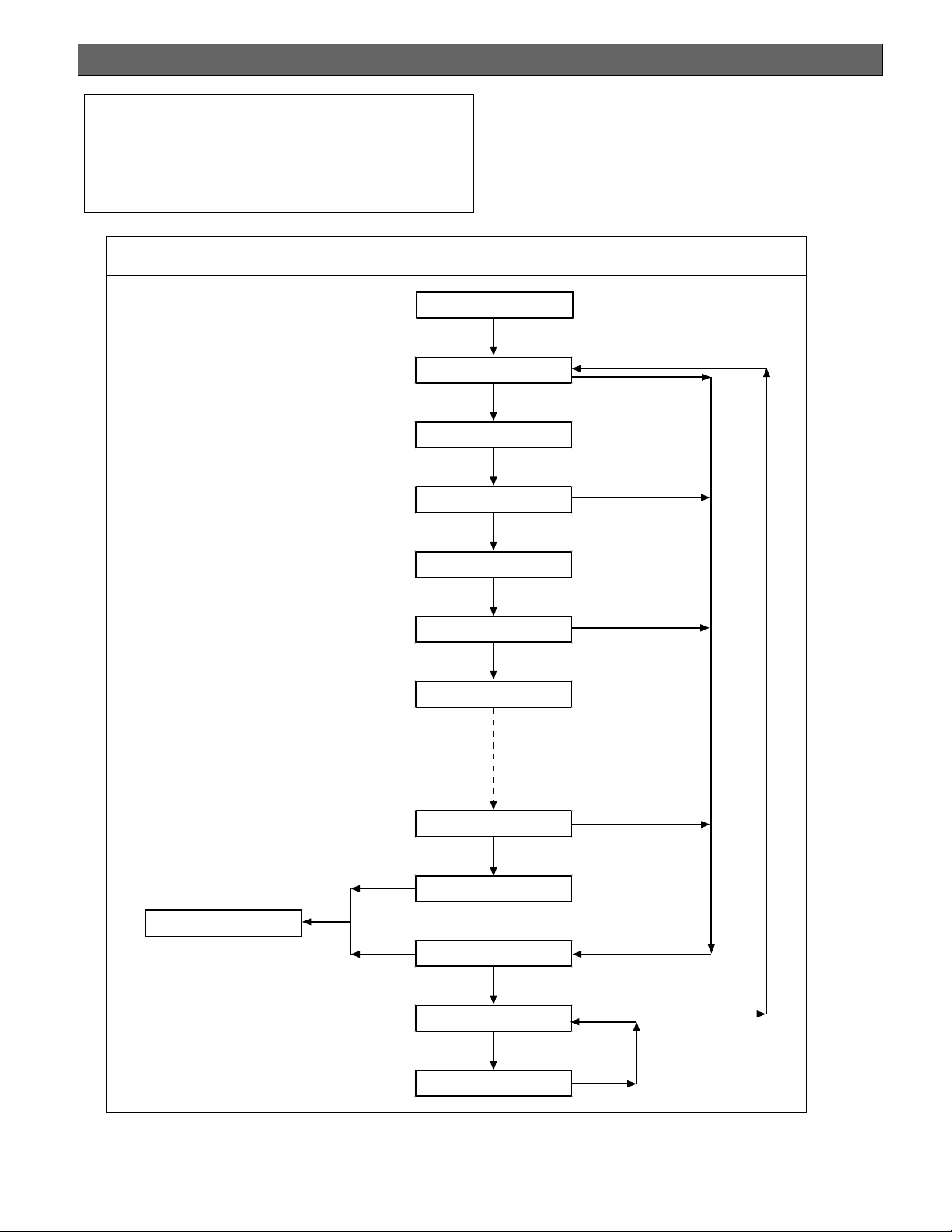
4.11 Service Walk Test
The Service Walk Test differs from the standard
Walk Test. In the standard Walk Test, point
expansion modules whose switches are set for a
point number not programmed in the control
panel do not appear in the test. In the Service
Walk Test, POPITs whose switches are set for a
point number that is not programmed in the
control panel do appear in the test.
The Service Walk Test allows a user to walk test
all 246 points from a control-panel-wide keypad,
regardless of the point index type.
A Service Walk Test can also be initiated by
account-wide or area-wide keypads but test only
those points that are within the scope of the
keypad that initiated the function. The Service
Walk Test does not test points in armed areas.
Only Walk Test Start and Walk Test
End are reported to the central
station.
During a Service Walk Test, the
summary alarm and summary fire
remain off, because there are no Fire
or Burg alarm conditions to
summarize. The P# Output Response
Type feature operates as
programmed.
The D7412GV4 does not include the
Service Walk Test in the Service Menu.
To enable the Service Walk Test
function for any GV4 Series Control
Panel, add its function code to the
Function List of a keypad.
Service Walk Test Procedure (B920/B930)
Refer to Walk Test procedures for Service Walk
Test options in compatible keypad
documentation when using a B920 or B930
Keypad.
1. Choose a keypad to conduct the test. Ensure
that the display shows the idle disarmed text.
2. Press the [MENU] key and then go to the [3]
Actions > [3] Test > [1]Walk Test > [3]
Service menu option.
3. Enter your passcode and press [ENTER]. The
keypad shows the number of points that
remain to be tested.
4. To view the points, press [ENTER] on a B920
keypad or press the View untested points
softkey on a B930 keypad. To scroll through
the list of points, use the [PREV] or [NEXT]
key.
5. When you fault a point (move in front of a
motion sensor for example), the keypad emits
a brief tone and shows the point name and
information (for example, Area-1 Point-7
Onboard: Short).
Extra Points display default text: If the switches
on a POPIT are set incorrectly to a point number
that is not in the program for the control panel,
the default text for that point number (PT ###)
appears when the point is faulted.
Faulting the point a second time produces the
tone and shows the point text, but does not
decrease the count in the ## PTS TO TEST
message.
To see the points that remain untested during the
Service Walk Test:
a. Press [ESC] when point text appears. The
display shows ## PTS TO TEST.
b. Press the [ESC] key. VIEW UNTESTED ?
appears.
c. Press [ENT]. ## PTS UNTESTED appears.
d. Press [NEXT] to see a list of the points
that have not yet been tested. Move
through this list by pressing the [NEXT]
key.
e. To resume the Service Walk Test, press
[ESC]. ## PTS UNTESTED appears.
f. Press [ESC]. ## PTS TO TEST appears.
g. Resume testing points. To end the Service
Walk Test, press [ESC] twice.
Bosch Security Systems, Inc. | 2/13 | F01U265457-03 21
Page 22
D9412GV4/D7412GV4 v2.00 | Installation and System Reference Guide | 4.0 Installation
.
6. After the last point is tested, 0 PTS TO TEST
appears. Press [ESC]. The display shows ALL
PTS TESTED briefly before returning to idle
text.
The Service Walk Test, when
performed on a D7412GV4, cannot
show “0 PTS TO TEST” because the
D7412GV4 is physically unable to
connect to the second POPEX Module
(used for Points 129-247).
Automatic time-out returns the system
to idle text: If there is no point or
keypad activity for 20 min., the
Service Walk Test ends automatically.
The keypad returns to idle text.
4.11.1 Program the Control panel
Use RPS or the keypads to program the control
panel. Refer to:
Control Panels (D9412GV4/D7412GV4
v2.00)) Program Entry Guide (P/N:
F01U265459).
Keypad Installer menu
RPS Help
4.11.2 Service Bypass
To facilitate system maintenance for service
personnel, a special point bypass option is
provided through this menu to remove any point
from service. The status of points in Service
Bypass can be viewed through the Service Bypass
Menu. For details in navigation and operation of
this function refer to the Control Panels
(D9412GV4/D7412GV4 v2.00) Program Entry
Guide (P/N: F01U265459).
4.11.3 RF Points and Repeaters
With a B810 wireless receiver, the control panels
can support up to 238 wireless points, 1000 key
fobs, and 8 repeaters within the RADION wireless
portfolio. The RF Points menu provides the tools
necessary to enroll, remove or replace wireless
points. For details in navigation and operation of
these functions refer to the Control Panels
(D9412GV4/D7412GV4 v2.00) Program Entry
Guide (P/N: F01U265459).
With a B820 SDI2 Inovonics Interface Module, the
control panels can support up to 350 RF devices
and up to eight RF Repeater modules. The RF
Points menu provides the tools necessary to
enroll, remove or replace wireless points. For
details in navigation and operation of these
functions refer to the Control Panels
(D9412GV4/D7412GV4 v2.00) Program Entry
Guide (P/N: F01U265459).
The RF Points menu does not affect
the RFIDs learned by the D8125INV
Wireless Interface Module nor the
ISW-D8125CW-V2 Commercial
Wireless Interface Module if installed
on the Zonex bus.
4.11.4 RF Diagnostics
With a B810 wireless receiver, or B820 SDI2
Inovonics Interface Module installed, the control
panel can show detailed wireless communication
information for RF points, keyfobs and repeaters.
The RF Diagnostics menu can show real-time
signal strength information for enrolled RF
devices. By monitoring the signal strength of an
individual RF device, the optimal position for
installation can be found.
RF device diagnostic information also includes AC
status, battery status, supervision status, and
tamper status for all supporting devices. For
details in navigation and operation of these
functions refer to the Control Panels
(D9412GV4/D7412GV4 v2.00) Program Entry
Guide (P/N: F01U265459).
4.11.5 IP Diagnostics
With at least one B420 Ethernet Communication
Module, or B426 Ethernet Communication
Module installed on the SDI2 bus, the control
panels can use the diagnostic functions of this
menu to retrieve the auto-configured settings
from the module and perform a series of network
communication tests. This menu does not apply
to the DX4020 modules on the SDI bus.
The Settings option retrieves the following from
the selected B420 module: Unit Host Name, MAC
ID, and current IPV4 Address. For the B426
module, the Settings option retrieves: Unit Host
Name, MAC ID, and current IPv6 Address.
The Connection Test option performs the
following automated tests for the selected
B426/B420 module:
Link [OK] if Ethernet cable is detected
[Missing] if Ethernet cable is not
detected.
Gateway [OK] if an ICMP echo request (PING)
response is received from the Gateway
Bosch Security Systems, Inc. | 2/13 | F01U265457-03 22
Page 23
D9412GV4/D7412GV4 v2.00 | Installation and System Reference Guide | 4.0 Installation
.
Address. [Failure] if response is not
received.
Internet [OK] if an ICMP echo request (PING)
response is received from the IP Test
Address. [Failure] if response is not
received.
Figure 5: Service Walk Test Flow Chart Example
SERVICE WALK?
246 PTS TO TEST
Refer to the Control Panels
(D9412GV4/D7412GV4 v2.00) Program Entry
Guide (P/N: F01U265459) for details on the
B426/B420 Ethernet Communication Module
configuration.
[ENT]
Test a device
POINT TEXT
(Text displays for 60 seconds)
[ESC]
IDLE TEXT
[ESC]
245 PTS TO TEST
Test a device
POINT TEXT
(Text displays for 60 seconds)
244 PTS TO TEST
Test a device
POINT TEXT
1 PTS TO TEST
Test a device
0 PTS TO TEST
[ESC]
[ESC]
[ESC]
VIEW UNTESTED?
[ENT]
# PTS UNTESTED
[NEXT]
POINT TEXT
[ESC]
[ESC]
Bosch Security Systems, Inc. | 2/13 | F01U265457-03 23
Page 24
.
D9412GV4/D7412GV4 v2.00 | Installation and System Reference Guide | 5.0 Power Supply
5.0 Power Supply
5.1 Primary Power Terminals 1 and 2
1 2
,
5.1.1 Primary (AC) Power Circuit
The primary source is a 16.5 VAC, 40 VA,
internally-fused transformer (Bosch Security
Systems, Inc. Model D1640). The control panel
draws 200 mA when idle and 300 mA when in an
alarm state. The total available auxiliary current is
1.4 A.
Transient suppressors and spark gaps protect the
circuit from power surges. This protection relies
on the ground connection at Terminal 10. Ensure
that you connect Terminal 10 to a proper ground.
Refer to Section 4.5 Connecting Earth Ground on
page 18.
AC Power Fail
The system indicates an AC power failure when
Terminals 1 and 2 do not have power. The AC Fail
Time parameter sets the number of minutes or
secs without AC power before the control panel
acknowledges the failure and the number of
minutes or secs after the power returns before
the control panel acknowledges restored power.
Refer to the Control Panels
(D9412GV4/D7412GV4 v2.00) Program Entry
Guide (P/N: F01U265459)for additional
information about AC Fail Time and UL 864
requirements.
5.1.2 Installing the Transformer
Do not short-circuit the terminals of the
transformer: Shorting the terminals
opens the internal fuse, causing
1. Use 18 AWG (1.22 mm) wire (minimum) to
2. Route telephone and sensor loop wiring away
permanent failure. Connect the
transformer to Terminals 1 and 2 of
the control panel before plugging it
into the power source.
connect the transformer to the control panel.
The wire length should be as short as
possible. The maximum length is 50 ft (15 m).
Connect the battery and plug in the
transformer.
from any AC conductors, including the
transformer wire.
AC wiring can induce noise and low level
voltage into adjacent wiring. Route data
wiring away from AC and telephone wiring.
Always connect the battery first and
then plug in the transformer.
3. Connect the battery. Refer to Section 5.2.2
Installing the Battery on page 25.
4. Plug the transformer into an unswitched, 120
VAC, 60 Hz power outlet only.
5. Secure the transformer to the outlet with the
screw provided.
D8004 Transformer Enclosure Required for Fire
Systems
Use the D8004 Transformer Enclosure for the
D1640 Transformer in fire and combined fire and
burglary applications.
Check with the Authority Having
Jurisdiction (AHJ) about mounting
transformers on specific circuits.
5.2 Secondary Power Terminals
5.2.1 Secondary (DC) Power
A 12 V sealed lead-acid rechargeable battery
(D126) supplies secondary power for auxiliary
and alarm outputs, and powers the system during
interruptions in primary (AC) power.
Use Lead Acid Batteries Only: The
charging circuit is calibrated for lead-
Extra Batteries Increase Back-up Time
To increase battery back-up time, connect a
second 12 V battery in parallel to the first
battery. Use a D122 Dual Battery Harness to
ensure proper and safe connection. Refer to the
Standby Battery and Current Rating Chart in 17.0
Approved Applications in this guide for battery
standby time calculations.
D1218 Battery
The D1218 is a 12 V, 18 Ah battery for use in
applications requiring extended battery standby
time. Up to two D1218 batteries can be
connected when used with a D122 Dual Battery
Harness.
acid batteries. Do not use gel-cell or
nicad batteries.
Caution: When connecting two D1218
Batteries to the control panel, both
must have the same capacity (use two
17.2 Ah batteries or two 18 Ah
batteries).
Bosch Security Systems, Inc. | 2/13 | F01U265457-03 24
Page 25
.
D9412GV4/D7412GV4 v2.00 | Installation and System Reference Guide | 5.0 Power Supply
When using two D1218 batteries, use
a separate enclosure, a D122L Dual
Battery Harness, and long leads.
5.2.2 Installing the Battery
1. Place the battery upright in the base of the
enclosure.
2. Locate the red and black leads supplied with
the control panel.
3. Connect the black battery lead to Terminal 4,
and then to the negative (-) side of the
battery.
4. Connect the red battery lead to Terminal 5,
and then to the positive (+) side of the
battery.
Warning: High current arcs are
possible. The positive (red) battery
lead and Terminal 5 can create high
current arcs if shorted to other
terminals or the enclosure. Use
caution when working with the
positive lead and Terminal 5. Always
disconnect the positive (red) lead
from the battery before removing it
from Terminal 5.
Caution: The battery terminals and
wire are not power limited. A 0.25 in
(6.4 mm) space must be maintained
between the battery terminals, battery
wiring, and all other wiring. Battery
wiring cannot share the same conduit,
conduit fittings, or conduit knock-outs
with other wiring.
Figure 6: Battery Terminals
1 - Battery terminals. Terminal 5 is non-power
limiting.
Bosch Security Systems, Inc. | 2/13 | F01U265457-03 25
Page 26
D9412GV4/D7412GV4 v2.00 | Installation and System Reference Guide | 5.0 Power Supply
.
Figure 7: Non-Power-Limited Wiring
1 - Conduit required for use with external
batteries.
2 - Battery wires
3 - 0.25 in (6.4 mm) minimum. To ensure proper
spacing, use tie-wraps or similar devices to
secure wires.
5.2.3 Replacing the Battery
Replace batteries every 3 to 5 years under normal
use. Record the date of installation directly on
the battery.
Caution: Exceeding the maximum
output ratings or installing the
transformer in an outlet that is
routinely switched off causes heavy
discharges. Routine heavy discharges
can lead to premature battery failure.
D8132 Boost Battery Backup: Adding a D8132
Battery Charger Module supports additional
batteries of up to 27 Ah capacity, if required.
The control panel, plus any connected D8132
Modules and/or a auxiliary power supply, must be
on the same AC circuit to discharge evenly if AC
power fails. The B520 does not need to be on the
same AC circuit as the control panel.
4 - Output wires
5 - Input or Point wires
6 - Standby battery 12 V sealed lead-acid
rechargeable battery D1246/D1218
Refer to the Standby Battery and Current Rating
Chart in the 17.0 Approved Applications of this
guide for battery standby time calculations.
D8132 Specifications
Operating Voltage
16.5 VAC supplied from
D1640 transformer
Operating Current 1200 mA of rectified AC
Float Voltage 13.9 VDC maximum
Dimensions (H x W x D)
0.75 in x 3.0 in x 5.0 in
(1.9 cm x 7.6 cm x 12 cm)
Bosch Security Systems, Inc. | 2/13 | F01U265457-03 26
Page 27
D9412GV4/D7412GV4 v2.00 | Installation and System Reference Guide | 5.0 Power Supply
.
The control panel and the D8132 (or
B520 Auxiliary Power Supply Module)
must share COMMON.
Figure 26 on page 61 shows the
common form of the D8132 Module
connected to the common on the
keypad and the common on the
control panel. Any stand-alone power
supply powering any device
connected to the control panel must
also be connected to a common
terminal on the control panel.
If using the ground fault detection
capability on the control panels with
an external power supply, ensure that
the external selected power supply
isolates its earth ground connection
from the negative side of the auxiliary
power output. External power
supplies that do not isolate earth
ground can cause ground fault
conditions on the control panel.
5.2.4 Battery Supervision
When battery voltage drops to 13.8 VDC, the
yellow Charging Status LED illuminates. When the
battery voltage drops to 12.0 VDC to 11.8 VDC,
the red Low Battery LED lights, and the keypad
or keypads display SERVC LOW BATT on the
keypad display. The control panel (if programmed
for power supervision) sends a BATTERY LOW
report in the Modem4 communication format. It
sends a Low System Battery (302) report in the
Contact ID format.
If the battery is missing or shorted, the red Low
Battery LED flashes at the same rate as the green
Operation Monitor LED. If the control panel is
programmed for power supervision, it sends a
BATTERY MISSING report in the Modem4
communication format, or Control Panel Battery
Missing (311) report in the Contact ID format.
When battery voltage returns to 13.7 VDC, the
Low Battery LED turns off and the keypad or
keypads clear the SERVC LOW BATT message on
the keypad display. If the control panel is
programmed for power supervision, it sends a
BATTERY RESTORAL report in the Modem4
communication format or a Control Panel Battery
Restored to Normal (302) report in the Contact
ID format. At 13.9 VDC, the yellow Charging
Status LED stops lighting.
Figure 8: Charging and Battery LEDs
LEDs Off When Nor mal
10.2 VDC - Battery Load Shed
Y ELLOW - Charging Statu s
RED - Low Battery - 12.1 VDC
Investigate Low Battery reports immediately: If
primary (AC) power is off and the discharge
continues, the control panel becomes inoperative
when the battery voltage drops below 10.2 VDC.
5.2.5 Battery Charging Circuit Float Charge
The float voltage for the battery charging circuit
is 13.9 VDC at a maximum current of 1.4 A, less
any devices connected to the control panel. If the
float voltage drops below 13.8 VDC due to
overload or battery discharge, the yellow
Charging Status LED lights.
Loss of AC Load Shed Output protects battery:
During an AC power loss, the battery supplies all
power to the security system. If the battery
voltage falls below 10.0 V during an AC power
loss, a load shed output isolates the battery from
the control panel and disables the control panel.
Load shed protects the battery from being
damaged by deep discharge.
When AC power restores, the load shed output
reconnects the charging circuit on the control
panel to the battery and the battery begins to
recharge.
Overcharge Load Shed With AC Present: If more
than 1.4 A of auxiliary current draw from the
control panel occurs, the battery supplies the
current and begins to discharge. If this situation
is not corrected, the battery continues to
discharge and at 11.8 VDC to 12.0 VDC, SERV
LOW BATT appears on the keypad display.
When the battery voltage drops below 10.0 VDC,
the control panel shuts down. Remove all loads
to the control panel and disconnect AC power.
Fix the condition creating the over current. Add a
new battery and reconnect AC power.
Bosch Security Systems, Inc. | 2/13 | F01U265457-03 27
Page 28

D9412GV4/D7412GV4 v2.00 | Installation and System Reference Guide | 5.0 Power Supply
.
A shorted battery condition is created either by a
shorted cell inside the battery or by a short on
Terminals 4 and 5. A shorted battery might cause
the control panel to operate in an unsafe way.
This condition generates WATCHDOG RESET
reports.
Reset the control panel by momentarily placing
the reset pin in the disable position. Refer to
Figure 4 on page 19. The red Low Battery LED
continues flashing until the control panel resets.
5.2.6 Battery Discharge and Recharge Schedule
Table 6: Battery Discharge and Recharge
Schedule
Discharge Cycle
AC Off:
13.9 VDC: Charging float level.
13.8 VDC: Charging status LED on.
12.0 VDC:
<
Ω 10.0
VDC:
Recharge Cycle
AC On:
13.7 VDC:
13.9 VDC:
AC Fail Report when AC fails, if
control panel is programmed to
report AC failure at occurrence.
Low Battery and AC Fail Reports if
programmed. Low battery LED on.
Battery load shed (processing
functions continue if AC is
present).
Load shed output reset; battery
charging begins; Battery Trouble
and AC Restoral Reports sent.
Battery Restoral Reports sent. Low
battery LED off.
Changing status LED off; battery
float charged.
Bosch Security Systems, Inc. | 2/13 | F01U265457-03 28
Page 29

D9412GV4/D7412GV4 v2.00 | Installation and System Reference Guide | 5.0 Power Supply
.
Table 7: Charging Status and Low Battery LEDs
LED
Type
Charging Status
LED
Yellow Off Battery is fully charged.
Yellow On
Yellow
Low Battery LED Red
Red Off Battery is fully charged.
Red On
Red
Yellow
Flash once per
minute
Flash
Action Color State
Shows the charging status of the battery. Refer to Figure 8
on page 27 for location.
If the battery is missing, shorted, or reversed, the Charging
Status LED is off, but the red Low Battery LED is flashing.
Battery float charge is below 13.8 VDC. If AC is present, the
battery is charging.
Indicates the combined current draw from all outputs
exceeds 1.4 A. This is normal under alarm conditions for
non-fire systems with sirens or bells drawing more than 1.4
A. If the LED lights regularly for extended periods or does
not go out, check the current draw for devices connected to
the power outputs. Refer to Section 6.0 Power Outputs on
page 30 for instructions.
System is checking the battery.
Shows the condition of the battery. Refer to Figure 8 on
page 27 for location.
Battery voltage dropped to between 12.0 VDC and 11.8 VDC.
LED turns off when voltage reaches 13.7 VDC.
Battery is missing or shorted.
Bosch Security Systems, Inc. | 2/13 | F01U265457-03 29
Page 30
D9412GV4/D7412GV4 v2.00 | Installation and System Reference Guide | 6.0 Power Outputs
.
6.0 Power Outputs
6.1 Circuit Protection
Three self-resetting circuit breakers protect the
control panel from short circuits on the
continuous and programmable power outputs. If
the control panel is programmed for power
supervision and a short circuit occurs on one of
the power outputs, the control panel sends
BATTERY LOW and BATTERY MISSING when
using Bosch Security Systems, Inc. Modem4
communicator format. Under the same conditions
when using Contact ID communicator format, the
control panel sends Control Panel Battery Low
(302) and Control Panel Battery Missing (311).
One self-resetting circuit breaker protects:
Terminal 3: Auxiliary Power
Terminal 24: Zonex Power
A short circuit on one terminal
disrupts power to the other terminal.
Another self-resetting circuit breaker protects:
Terminal 6: Alarm Power Output
Terminal 7: Alternate Alarm Power Output
Terminal 8: Switched Auxiliary Power.
A short circuit on one of the terminals
disrupts power to the other two
The third self-resetting circuit breaker protects
Terminal 32: Power +.
6.2 Total Available Power
The system produces up to 1.4 A of combined
power at 12.0 VDC nominal for special
application use. The outputs listed below share
the available power. These outputs are shown as
red circles on the faceplate.
3
devices requiring continuous power.
terminals.
UL requires any device powered from
a power output to be supervised.
UL requires that power outputs are
not shared between fire and non-fire
devices unless all devices are in
conduit within 20 ft and are in the
same room.
Auxiliary Power: Use this terminal to power
6
(Output A) - Alarm Power Output:
Programmable output normally open, power on
alarm.
7
(Output B) - Alternate Alarm Power Output:
Programmable output normally open, power on
alarm.
8
(Output C) - Switched Auxiliary Power:
Programmable output normally closed, switches
power off when the Sensor Reset command is
executed.
24
Zonex Power: Use this terminal to power
Zonex modules such as the D8125, D8128D, and
D8129 Modules.
32
SDI Power +: Use this terminal to power
serial device interface (SDI) devices such as
keypads, or the D9210C Access Control Interface
Modules.
36
SDI2 Power +: Use this terminal to power
serial device interface (SDI2) devices such as the
B208 Octo-input Module, the B308 Octo-output
Module, the B426/B420 Ethernet Communication
Module, RADION wireless receiver, B920 Two-line
Alphanumeric Keypad, B930 ATM Style
Alphanumeric Keypad, and the B820 Inovonics
Interface Module.
Accessory Connector: The D928 Dual Phone Line
Switcher connects to the accessory connector.
6.3 Continuous Power Output
Terminals 3, 8, 24, and 32
24 32
3
8
, , ,
The continuous current draw for powered devices
connected to Terminals 3, 8, 24, and 32, and the
accessory connector must not exceed 1.4 A.
Devices powered from these outputs operate at
12.0 VDC Nominal.
Power Restricted for Fire and Combined Fire and
Burglary Systems: Use the Fire System Power
Formula to calculate the current available for fire
and combined fire and burglary systems (refer to
Section 6.4 Programmable Power Output Terminals
6, 7, and 8).
6.4 Programmable Power Output
Terminals 6, 7, and 8
6 7
, ,
8
Bosch Security Systems, Inc. | 2/13 | F01U265457-03 30
Page 31

D9412GV4/D7412GV4 v2.00 | Installation and System Reference Guide | 6.0 Power Outputs
.
6.4.1 Programming
The power outputs at Terminals 6, 7, and 8 are
programmed as Outputs A, B, and C. All outputs
are programmed in the Outputs section.
Outputs are assigned a output type, (Fire Bell, for
example) when they are assigned to an area.
Outputs can be assigned to one or more areas.
The Bosch Security Systems, Inc. defaults set Output
A (Terminal 6) as a Steady Alarm Bell output,
Output B (Terminal 7) as a Pulsed Fire Bell
output, and Output C (Terminal 8) as a
Verification or Reset output for smoke detectors.
The Control Panels (D9412GV4/D7412GV4 v2.00)
Program Entry Guide (P/N: F01U265459)contains
complete instructions for programming outputs.
Refer to Sections 6.4.2 Terminals 6 and 7, 6.4.3
Fire System Power Formula, and 6.4.4 Terminal 8
on page 31 for descriptions of the functions of
each terminal.
Refer to the Bell Parameters section of the
program to set the Fire Bell, Alarm Bell output
responses for outputs. Four annunciation
patterns are available: Steady, Pulsed, California
Standard, and Temporal Code 3.
Voltage Output at Terminals 6, 7, and 8
If Terminals 6, 7, and 8 do not provide the
expected output, check:
Programming for Outputs A, B, and C in
the outputs section of the program.
Bell Parameters section of the program to
confirm that the Alarm and Fire Bell
responses are programmed for the
expected duration and pattern.
Point Assignments section to confirm that
each point is programmed for the
expected local response.
6.4.2 Terminals 6 and 7
When activated, Terminals 6 (Output A) and 7
(Output B), provide positive (+) 12.0 VDC
Nominal power output. Use the power at
Terminals 6 and 7 to power bells, siren drivers,
piezoelectric fire sounders, electronic horns, or
other devices.
Programming determines the format of the
output and the conditions that activate it. One
self-resetting circuit breaker protects Terminals
6, 7, and 8 against shorts.
When using Output A or Output B to activate
notification appliance circuits in UL Listed fire
alarm applications, install a D192G Indicating
Circuit Module.
Power Restricted for Fire and Combined Fire and
Burglary Systems: Fire systems are prohibited
from using the battery for determining alarm
power. Use the fire system power formula that
follows to calculate the current available for fire
and combined fire and burglary systems.
6.4.3 Fire System Power Formula
To calculate the current available at Terminals 6
and 7 for fire and combined fire and burglary
systems:
1. Add together the current draws for all devices
connected to Terminals 3, 8, 24, and 32, and
the accessory connector. This is the total
current required for the normal standby
condition (NSC).
2. The current available for NSC is 1.4 A.
Subtract the NSC current required calculated
in Step 1 from the NSC current available, 1.4
A. The difference is the alarm current
available for Terminals 6 and 7.
In formula format:
=
1.4 A NSC current
required (Step 1)
Alarm current
available
Refer to the Approved Applications chapter of this
guide for module or accessory current
requirements.
6.4.4 Terminal 8
Terminal 8 provides continuous positive (+) 12.0
VDC Nominal power. Output C interrupts the
power at Terminal 8 when activated. Use
Terminal 8 to power smoke detectors or other
devices that are reset by interrupting power. One
self-resetting circuit breaker protects Terminals
6, 7, and 8 against shorts.
Verification and Reset Output
The default program sets Output C (Terminal 8)
as a verification and reset output. Refer to Output
Parameters and Point Assignments in the Control
Panels (D9412GV4/D7412GV4 v2.00) Program
Entry Guide (P/N: F01U265459) for instructions
on programming verification and reset outputs
and points.
Performing a sensor reset at a keypad produces a
five-sec output activation of verification and reset
outputs. The control panel ignores verification
and resettable points during the five sec.
Bosch Security Systems, Inc. | 2/13 | F01U265457-03 31
Page 32

.
D9412GV4/D7412GV4 v2.00 | Installation and System Reference Guide | 7.0 Telephone Connections
7.0 Telephone Connections
7.1 Registration
The Bosch Security Systems, Inc. D9412GV4 and
D7412GV4 Control Panels are registered with the
Federal Communication Commission (FCC) under
Part 68, for connection to the public telephone
system using an RJ31X or RJ38X jack installed by
the local telephone company.
7.2 Notification
Do not connect registered equipment to party
lines or coin-operated telephones. Notify the
local telephone company and provide the
following information before connecting the
control panel to the telephone network:
The particular line to which the control
panel will be connected
Make (Bosch Security Systems, Inc.),
model (D9412GV4 or D7412GV4), and
serial number of the control panel
FCC registration number:
US:ESVOT00BD9412GV4
Ringer equivalence for the control panel:
0.0B
7.3 Location
To prevent jamming of signals, wire the RJ31X or
RJ38X jack before the in-house telephone system
to support line seizure (Figure 9). Install the jack
on the street side of the telephone switch, wired
ahead of any PBX equipment. Line seizure
temporarily interrupts normal telephone usage
while the control panel sends data. After
installation, confirm that the control panel seizes
the line, acquires dial tone, reports correctly to
the receiver, and releases the telephone line to
the in-house telephone system.
Figure 9: RJ31X/RJ38X Wiring (RJ31X shown)
1 - Outside Telco
2 - Premises telephone
3 - Bar short removed on Telco connector block
insertion – positions 1 and 4 and 5 and 8
4 - RJ31X/RJ38X jack
5 - Telco connector jack
6 - To control panel
7.4 Telephone Cord Connection
Connect one end of a D162 [2 ft (61 cm)]
Telephone Cord to the telco cord connector
located on the bottom left corner of the control
panel. Refer to Figure 10. Connect the other end
to the RJ31X or RJ38X jack.
To supervise the phone cord, use an
RJ38X jack.
Bosch Security Systems, Inc. | 2/13 | F01U265457-03 32
Page 33

D9412GV4/D7412GV4 v2.00 | Installation and System Reference Guide | 7.0 Telephone Connections
.
Figure 10: Phone Connector, Phone LED, and Operation Monitor LED Locations
1 - Phone LED (red)
2 - Telephone cord connector
7.5 Phone LED (Red)
The red Phone LED illuminates when the control
panel seizes the telephone line and remains
illuminated until the control panel returns the
telephone line. Refer to Figure 10 on page 33 for
the location of the red LED.
7.6 Operation Monitor LED (Green)
The green Operation Monitor LED indicates the
operation of the central processing unit (CPU).
When the CPU is operating normally, the LED
flashes 0.5 sec on, 0.5 sec off.
This green LED also serves as a ring indicator.
The Operation Monitor LED is located on the
lower right side (Figure 10 on page 33). When
there is ring voltage on the telephone line (the
telephone is ringing), the green LED flashes at a
faster rate for the duration of each ring. Ring
voltage must reach a minimum of 45 VAC before
the system detects it.
7.7 Dialing Format
The system can be programmed to use dual tone
multi-frequency (DTMF) or pulse dialing. Refer to
Phone Parameters in the Control Panels
(D9412GV4/D7412GV4 v2.00) Program Entry
Guide (P/N: F01U265459).
7.8 Telephone Line Monitor
The control panel has a built-in telephone line
monitor that tests the telephone line for voltage
and current. If the D928 Dual Phone Line
Switcher is used to connect two telephone lines
to the control panel, both lines are monitored.
The normal voltage on a telephone line is
approximately 48 VDC (24 VDC for some
telephone systems).
3 - Operation Monitor LED (green)
If the control panel senses trouble, it starts a
programmable telephone line trouble timer,
which continues to run as long as the monitor
detects trouble. It resets to zero when the
control panel senses a normal line. If the timer
reaches the delay time in the Phone Supervision
program item, it begins a telephone line trouble
response. Programming determines what the
response is. For programming information, refer
to Phone Parameters in the Control Panels
(D9412GV4/D7412GV4 v2.00) Program Entry
Guide (P/N: F01U265459).
Any time the control panel uses the telephone
line to make a call or is on-line with the remote
programming software (RPS), it stops monitoring
the telephone line during this process. When the
telephone line on the control panel is no longer in
use, it begins to monitor the telephone line again.
Bad Line Might Test OK: The telephone line
monitor uses voltage levels to test the status of
the telephone line. In some instances, a given
telephone line might be out of service without
affecting the voltage on the line. The telephone
line monitor cannot recognize this trouble
condition.
Bosch Security Systems, Inc. | 2/13 | F01U265457-03 33
Page 34

D9412GV4/D7412GV4 v2.00 | Installation and System Reference Guide | 7.0 Telephone Connections
.
7.9 Called Party Disconnect
Telephone companies provide “called party
disconnect” to allow the called party to terminate
a call. The called party must go on hook (hang
up) for a fixed interval before a dial tone is
available for a new call. This interval varies with
telephone company equipment. Control panel
firmware allows for “called party disconnect” by
adding a 35-sec, “on hook” interval to the dial
tone detect function. If the control panel does
not detect a dial tone in 7 sec, it puts the
telephone line on hook for 35 sec to activate
“called party disconnect,” goes off hook, and
begins a seven-second dial tone detect.
If no dial tone is detected, the control panel dials
the number anyway. Each time the number is
dialed, the control panel records this as an
attempt.
7.10 Communication Failure
If a backup route is configured and the first two
attempts to reach the receiver over the phone
line fail, the system switches to the backup route.
When it switches to the backup route, a COMM
TROUBLE PH # event is sent, and the event that
triggered the telephone call to the central station
follows.
After ten unsuccessful attempts to reach the
receiver, the control panel enters communication
failure. The control panel clears any reports
queued for the failed route and a COMM FAIL #
event is generated and display at the keypads. A
trouble sounder can be programmed to
annunciate at the keypads.
One hour after the COMM FAIL # is generated,
the control panel attempts to send a restoration
event. If a communication failure still occurs, the
keypad trouble sounds again.
If the D928 Dual Phone Line Switcher is used, the
control panel makes a total of ten attempts
before entering communication failure.
Enhanced Communication
The control panels can send events over the SDI
Bus through a DX4020 Network Interface Module
(NIM) or over the SDI2 bus through a B426/B420
NIM. For more information on the enhanced
communications capabilities, refer to the Control
Panels (D9412GV4/D7412GV4 v2.00) Program
Entry Guide (P/N: F01U265459).
7.11 D928 Dual Phone Line Switcher
7.11.1 Description
The optional D928 Dual Phone Line Switcher
allows the D9412GV4 and D7412GV4 Control
Panels to send reports over two separate
telephone lines. If a telephone line is not within
the operating range, the control panel attempts
to use the other telephone line to send the
message. If trouble is detected, the control panel
keeps the faulty telephone line in memory.
Set the Ring Count above 2 on Answering
Machines: The control panel’s RPS line monitor
feature might not operate correctly if an
answering machine with a ring count of less than
two rings is connected to a telephone line used
by the D928 Module.
7.11.2 Operation
Refer to Phone and Phone Parameters section of
the Control Panels (D9412GV4/D7412GV4 v2.00)
Program Entry Guide (P/N: F01U265459)for
telephone supervision and reporting options. To
use the D928, set the Two Phone Lines prompt to
Yes.
When the D928 is installed, the control panel
alternates between Phone Line 1 and Phone Line
2 to send its first report. For example, on day
one, the control panel first attempts to
communicate on Phone Line 1. On day two, the
control panel switches and attempts to
communicate on Phone Line 2.
Any time the control panel resets or is
powered down or up, the next reported
With the D928 Dual Phone Line Switcher
installed, the control panel uses two telephone
lines (primary and secondary) to dial up to four
telephone numbers.
When using a primary and a backup device within
a Route Group #, the control panel makes two
attempts on the primary telephone line using the
Primary Device # as programmed. If these two
attempts fail, the control panel switches to the
secondary telephone line using the Backup Device
# as programmed. This pattern continues for a
total of ten attempts. After ten unsuccessful
attempts, the control panel generates a Comm
Fail event for the given Route Group #.
event always attempts to call out on
Phone Line 1 first.
If Phone Line 2 is not in service on “Day
2”, the control panel switches to the
primary phone line to send the report.
Bosch Security Systems, Inc. | 2/13 | F01U265457-03 34
Page 35

D9412GV4/D7412GV4 v2.00 | Installation and System Reference Guide | 7.0 Telephone Connections
.
Figure 11: D928 Dual Phone Line Switcher
1
+
+
7.11.3 Installing the D928
Mounting
Mount the D928 on the lower right side of the
enclosure using the screws provided with the
switcher.
Wiring
2
3
4
5
6
The D928 has two flying leads. The green lead
monitors AC power. The black lead is the ground
reference for the AC Power LED.
1. Connect the green lead from the D928 to
Terminal 1.
2. Connect the black lead from the D928 to
Terminal 9.
Telephone Connections
7
1. Plug one end of the ribbon cable provided
into J4 on the D928. Plug the other end of the
8
ribbon cable into the ACCESSORY connector
on the control panel.
9
2. Plug one end of the D162 phone cord
provided into the TELCO jack. Plug the other
10
end of the phone cord into the TELCO jack on
the control panel. Refer to Table 8 for phone
cord lengths.
11
1 - Connect to ACCESSORY CONNECTOR with
ribbon cable.
2 - Green to Terminal 1
3 - Black to Terminal 9
4 - AC Power LED (green)
5 - Phone jack to primary phone line
6 - Primary Fail LED (yellow)
7 - Phone jack to secondary phone line
8 - Secondary Fail LED (yellow)
9 - Phone jack to telco connector
10 - Communications Fail LED (yellow)
11 - Buzzer
Table 8: Phone Cord Lengths
Phone Cord Length
D162 2 ft (61 cm)
3. Plug one end of a D162 phone cord into J1 on
the control panel. Plug the other end of the
phone cord into the RJ31X or RJ138X for the
primary telephone line.
4. Plug one end of a D162 phone cord into J2 on
the control panel. Plug the other end of the
phone cord into the RJ31X or RJ138X for the
secondary telephone line. Refer Table 8 for
phone cord lengths.
7.11.4 D928 Status LEDs
Four LEDs mounted on the front edge of the
D928 Module show the status of AC power for
the control panel, the status of the two telephone
lines, and communication failure (Figure 11 on
page 34). When programmed and operating
normally, only the green AC power status LED is
lit.
AC Power LED
The green AC Power Status LED lights when AC
power is applied to Terminals 1 and 2 on the
control panel.
Bosch Security Systems, Inc. | 2/13 | F01U265457-03 35
Page 36

D9412GV4/D7412GV4 v2.00 | Installation and System Reference Guide | 7.0 Telephone Connections
.
Phone Line Fail LEDs
Two yellow Phone Line Status LEDs (one for the
primary telephone line, one for the secondary
telephone line) light if the telephone line is not
within the operating range. The control panel
monitors the faulty telephone line for the
programmed interval before indicating a trouble
condition. Refer to Section 7.8 Telephone Line
Monitor on page 33 for a description of phone
line monitor operation.
Communication Failure LED
The yellow Communication Failure LED lights
when the system is in communication failure. The
LED turns off when communication restores.
Refer to Section 7.10 Communication Failure on
page 34.
Dedicated telephone lines might be
required for UL 864 Commercial Fire
applications. Check with your
Authority Having Jurisdiction (AHJ).
Bosch Security Systems, Inc. | 2/13 | F01U265457-03 36
Page 37

D9412GV4/D7412GV4 v2.00 | Installation and System Reference Guide | 8.0 On-Board Points
.
8.0 On-Board Points
8.1 Terminals 11 to 22 Description
The control panel provides eight on-board points.
Each point functions independently and does not
interfere with the operation of the others. The
control panel monitors the sensor loops for
normal, shorted, or open conditions between an
input terminal (11, 13, 14, 16, 17, 19, 20, or 22)
and any of the point common terminals (12, 15,
18, and 21). The programming for the point
determines how the control panel responds to
those conditions. Refer to the Control Panels
(D9412GV4/D7412GV4 v2.00) Program Entry
Guide (P/N: F01U265459)for point programming
options. The control panel also monitors the
sensor loops for ground fault conditions if S4 is
latched (ground fault detect enabled).
8.2 Point Sensor Loops
Not for use in Fire Applications.
When wiring the on-board points (Figure 12),
install a 1 k Ω resistor at the far end of the sensor
loop to provide a reference for supervision. Drycontact sensing devices can be connected in
series (normally-closed) or in parallel (normallyopen) to any of these loops.
The number of normally-open and normallyclosed detection devices each sensor loop can
supervise is limited only by the resistance on the
loop. The total resistance for the wire length and
contacts, minus the end-of-line (EOL) resistor,
must not exceed 100 Ω.
8.3 Point Parameters
The condition of on-board Points 1 to 8 is
determined by measuring the voltage across the
point input terminal and one of the common
terminals. The sensor loops must be connected
and the 1 k Ω EOL resistor in place.
Table 9: Point Parameters
Loop Voltage Range
Open
Normal
Shorted
Greater than 3.7 VDC, but less than 5.0
VDC.
Greater than 2.0 VDC, but less than 3.0
VDC.
Greater than 0.0 VDC, but less than 1.3
VDC.
Figure 12: On-board Point Sensor Loop Wiring
1 - 100 Ω maximum Loop resistance
2 - Point input terminal
3 - Point common terminal
4 - Normally-closed contacts (NC)*
5 - Normally-open contacts (NO)
6- Combination: Normally-open contacts and
normally-closed contacts (NO/NC)
7 - P105F (Package of 8 EOL resistors) or
P105BL (Package of 8 UL Listed EOL
resistors) (P/N: 15093130-0040) or ICP1K22AWG-10 (This is a listed 10 pack of 1K
ohm resistors)
8 - Brown
9 - Black
10 - Red
* UL does not allow normally-closed loops for commercial fire applications.
Bosch Security Systems, Inc. | 2/13 | F01U265457-03 37
Page 38

D9412GV4/D7412GV4 v2.00 | Installation and System Reference Guide | 8.0 On-Board Points
.
8.4 Point Response Time
The control panel scans on-board and off-board
point sensor loops every 300 ms. The Debounce
program item in the Point Assignment section of
the software determines point response time by
setting the number of times the control panel
scans a point before generating an alarm.
The debounce count can range from 2 to 15;
therefore, point response time ranges from 600
ms to 4.5 sec. The Bosch Security Systems, Inc.
default for debounce count is 2.
Increasing debounce might cause
missed alarms. If you increase the
debounce count, detection devices
can enter alarm and reset without
exceeding the point response time.
Use a debounce count of 2 for all points except:
Use 3 for Interior Follower points.
Use 4 for door points connected to a
D9210C Access Control Interface Module.
8.5 Wiring Information for Installations
Using the Rothenbuhler
5110/4001-42 High Security Bell
4. Mount the D8108A’s 4001-42 External
Balanced Line Module and wire it to the 5110
Logic Board using two-conductor 22 AWG
(0.8 mm) cable.
5. Wire the 4001-42 to the control panel. Refer
to Figure 14 on page 40 and the Rothenbuhler
installation manual.
6. Before supplying AC and DC power to the
control panel and bell, ensure you are
wearing ear protection. The bell sounds for 2
sec and then silences during power up.
For additional information about bell
requirements, refer 17.3 Bank Safe and
Vault Applications found in 17.0 Approved
Applications.
Warning: Wear ear protection when
installing and testing the Rothenbuhler
High Security Bell.
Sound levels greater than 95 dBA at
3 m (10 ft) can occur.
The UL Listed Model 5110 Bell and Model 400142 External Line Balancer (both made by
Rothenbuhler) must be used for the bell and
balanced line module in bank safe and vault
applications.
1. Remove all power from the control panel.
2. Use six-conductor 18 AWG (1.2 mm) shielded
stranded wire between the control panel and
the 5110 Logic Board (located in the bell
enclosure).
3. If you do not have a Silence switch,
temporarily install a 1 resistor across TB1-1
and TB1-6 on the 5110 Logic Board. The
resistor keeps the 5110’s bell silent during
the installation and alignment procedures.
Also place a temporary wire jumper across
the TB1-6 Bell Relay and TB1-7. Refer to
Figure 14 on page 40 for wiring a Silence
switch.
Bosch Security Systems, Inc. | 2/13 | F01U265457-03 38
Page 39

D9412GV4/D7412GV4 v2.00 | Installation and System Reference Guide | 8.0 On-Board Points
.
Figure 13: Rothenbuhler 5110/4001-42 High Security Bell Wiring Configuration
1
0.64 mm (1/4 in.)
minimum distance
9
10
14
16
15
2
8
11
13
10
3
4
+
12
17
1
6
5
7
-
+
11
-
1 - Self-contained vibration sensor
2 - Control panel
3 - Accessory modules
4 - High line security module
5 - 4001-42 Balanced Line Module
6 - 5110 Bell
7 - D133 Relay
8 - Alarm zone input
9 - D122/D122L Battery Harness
1
Use Terminal 11, 13, 14, 17, 19, 20, or 22. (Select only one.)
2
Use a D113 Battery Lead Supervision Module to supervise the battery connections.
1
2
10 - D126 Battery
11 - D8108A Enclosure
12 - D122/D122L Battery Harness
13 - Proximity/control unit
14 - Normally open (NO)
15 - Normally closed (NC)
16 - End-of-line (EOL) resistor
17 - Safe
2
Bosch Security Systems, Inc. | 2/13 | F01U265457-03 39
Page 40

D9412GV4/D7412GV4 v2.00 | Installation and System Reference Guide | 8.0 On-Board Points
.
Figure 14: Wiring the Rothenbuhler 5110/4001-42 High Security Bell to the Control Panel
4
11
N/O 1
COMM 1
N/C 1
X1 -
X1+
1
123 6
12
13
1
9
2
3
4
9
2
RED ORG WHT BLK
9
10
6
7
9
6
3
7
8
3
5
1 - 5110 Logic Board
2 - 4001-42 External Line Balancing Module
3 - D9412GV4 or D7412GV4 Control Panel
4 - Alarm output
5 - Alternate alarm
6 - Common
7 - +12.0 VDC
* Use Terminal 11, 13, 14, 17, 19, 20, or 22. (select only one.)
8 - Alarm zone input*
9 - 10 k
10 - Optional Silence switch
11 - D133 Relay Module
12 - BBL In 4
13 - BBL Out 5
14 - Terminal TB1
resistor
Bosch Security Systems, Inc. | 2/13 | F01U265457-03 40
Page 41

D9412GV4/D7412GV4 v2.00 | Installation and System Reference Guide | 9.0 Off-Board Points
.
9.0 Off-Board Points
9.1 Zonex Buses
9.1.1 POPIT Modules
The D9412GV4 can use point of protection input
transponder (POPIT) modules to provide a
maximum of 238 off-board points, bringing the
total number of points the D9412GV4 can
monitor to 246. The D7412GV4 provides up to 67
off-board points, bringing the total number of
points the D7412GV4 monitors to 75. Each offboard point requires a POPIT Module.
The expansion bus can be shared
between fire and non-fire devices
where the POPIT module provides
data isolation between the input and
the bus connections.
9.1.2 POPEX Modules
POPITs connect to supervised two-wire data
expansion loops run from POPIT to POPIT
throughout the premises. Data expansion loops
connect to a D8125 Point of Protection Expander
(POPEX) Module. POPEX Modules have power
and data connections to the point bus on the
control panel (Table 10).
Table 10: POPEX Modules
Model Power Data
D9412GV4
D7412GV4
9.1.3 Missing Conditions
If a programmed POPIT is disconnected from the
expansion loop, a missing condition appears
immediately and the event is logged. The missing
condition might also be sent to a central station
or printed to an on-site printer, if programmed to
do so. Refer to the Control Panels
(D9412GV4/D7412GV4 v2.00) Program Entry
Guide (P/N: F01U265459) for programming
options.
Terminals 23 and
24
Terminals 23 and
24
Terminals 25 and
26 or
Terminals 27 and
28
Terminals 27 and
28
9.1.4 Control Panel Responses to Missing Point
Conditions
D9412GV4 and D7412GV4 respond to missing
point conditions based on the point’s
programming and the turned on (armed) state of
the point’s area. For example, if an interior
motion detector point is missing during a turned
off (disarmed)state, a Missing Trouble event is
generated; however, if the point is missing while
the area is Master Armed, a Missing Alarm event
is generated. Non-fire, 24-hour points always
generate a Missing Alarm event, whereas Fire
points always generate a Missing Fire Trouble
event.
9.2 D8125 and D9127 POPIT Modules
D9127 POPITs use the D8125 POPEX Module to
report to the control panel. Each D8125 supports
up to 119 POPIT points. Connect two D8125
Modules to the D9412GV4 to bring the combined
total number of POPIT and on-board points to
246.
Points 9 to 127 connect to the first
POPEX Module.
Points 129 to 247 connect to the second
POPEX Module.
The D9412GV4 reserves Points 128 and
248 for internal use.
The control panel annunciates activity only for
each POPIT, not for each detection device
connected to the sensor loop.
D9127 Module enclosures are made of UL Listed
fire resistant material. D9127T Modules contain
tamper switches. D9127U Modules include
untampered covers. Unless the module is
mounted in a tampered enclosure, UL requires
D9127T Modules for certificated accounts.
Listings
D8125 POPEX and D9127 POPIT Modules are UL
Listed for Local or Police Connected Burglar
Alarm, Central Station Burglar Alarm, Household
Burglar Alarm, Central Station Fire, Local Fire,
Remote Station Fire, Household Fire, and
Electrically Actuated Transmitter Applications.
Refer to 17.0 Approved Applications to determine
the required equipment and enclosures for the
application.
Bosch Security Systems, Inc. | 2/13 | F01U265457-03 41
Page 42

D9412GV4/D7412GV4 v2.00 | Installation and System Reference Guide | 9.0 Off-Board Points
.
Figure 15: Connecting the D8125 POPEX to the D9412GV4 Control Panel
1 - D8125 POPEX Module
2 - Switch block
3 - D9127 Sensor Loop
4 - 33 k Ω EOL resistor (P/N: P106F [15-03130-
002], package of eight)
For system supervision, do not use looped wire terminals. Break the wire run to provide
supervision of the connections.
5 - Point expansion loop
6 - Up to 119 POPITs
7 - Expansion points
Bosch Security Systems, Inc. | 2/13 | F01U265457-03 42
Page 43

D9412GV4/D7412GV4 v2.00 | Installation and System Reference Guide | 9.0 Off-Board Points
.
Figure 16: Connecting the D8125 POPEX to the D7412GV4 Control Panel
1 - D8125 POPEX Module
2 - Switch block
3 - D9127 Sensor Loop
4 - 33 k Ω EOL resistor (P/N: P106F [15-03130-
002], package of eight)
For system supervision, do not use looped wire terminals. Break the wire run to provide
supervision of the connections.
9.3 Installing the D8125 POPEX Module
For information on the Multiplex Bus
Interface, refer to the D8125MUX
Save the POPIT Label Sheets: The D8125 is
packaged with two sets of POPIT label sheets.
One set is marked “Bank 1” for use with the
D7412GV4. The other set is marked “Bank 2” for
use with the D9412GV4 and D9112. Use the
sheets later to label the POPITs. Refer to Section
9.3.6 POPIT Module Point Assignments on page 45.
9.3.1 Mounting
To install the D8125 in the enclosure with the
control panel:
Multiplex Bus Interface Operation and
Installation Guide (P/N: F01U034973).
5 - Point expansion loop
6 - Up to 119 POPITs
7 - Expansion points
1. Align the D8125 POPEX Module with any of
the four mounting locations in the enclosure
(Figure 2 on page 17).
2. Using the screws provided with the module,
secure it in the enclosure.
9.3.2 Wiring the D8125 to the Control Panel
To wire one or two D8125 Modules to the control
panel (Figure 15 on page 42 or Figure 16 on page
43):
Power Down the Control Panel: Disconnect the
positive (red) battery lead at the battery and
unplug the transformer.
For Points 9 to 127 (9 to 75 on D7412GV4):
1. Connect the GND terminal of the D8125 to
Terminal 23 on the D9412GV4 or to Terminal
9 on the D7412GV4.
Bosch Security Systems, Inc. | 2/13 | F01U265457-03 43
Page 44

D9412GV4/D7412GV4 v2.00 | Installation and System Reference Guide | 9.0 Off-Board Points
.
2. Connect the OUT terminal of the D8125
POPEX Module to ZONEX IN 1, Terminal 27.
3. Connect the IN terminal of the D8125 POPEX
Module to ZONEX OUT 1, Terminal 28.
4. Connect the AUX terminal of the D8125 to
Terminal 24 on the D9412GV4 or to Terminal
3 on the D7412GV4.
For Points 129 to 247 (D9412GV4 only):
1. Connect the GND terminal of the D8125 to
Terminal 23.
2. Connect the OUT terminal of the D8125
POPEX Module to ZONEX IN 2, Terminal 25.
3. Connect the IN terminal of the D8125 POPEX
Module to ZONEX OUT 2, Terminal 26.
4. Connect the AUX terminal of the D8125 to
Terminal 24.
Refer to Section 9.3.4 Wiring Data Expansion
Loops to POPEX Modules on page 44 for
instructions on connecting POPITs to the D8125
POPEX Module.
9.3.3 Wiring POPITs to the Data Expansion Loop
Use one two-wire data expansion loop or
distribute the POPITs on up to three loops.
Setting DIP switches on the POPIT Modules
assigns them to point numbers. Refer to Section
9.3.6 POPIT Module Point Assignments on page 45.
Review Section 4.6.2 Installing and Wiring
Detection Devices on page 19 to determine if
shielded wire is required. Refer to Table 11 to
determine the wire gauge for the length of each
data expansion loop.
Table 11: Data Expansion Loop Wire
Specifications
Maximum Length of All Data Expansion Loops
Combined
AWG Length in Feet (Meters)
22 1800 (548)
20 2890 (881)
18 4600 (1402)
16 7320 (2231)
14 11,650 (3551)
Combine Data Expansion Loops
The maximum lengths shown in Table 11 are for
all data expansion loops connected to the same
POPEX Module combined.
Wiring POPITs Together
Do not connect POPITs to each other
in series or with a T-tap. Doing so
might cause random missing POPIT
conditions.
Before installing the POPITs, ensure
that the resistance on the data
expansion loop is no more than 40 .
To connect POPITs to one another in parallel:
1. Connect the positive (+) data terminal from
one POPIT to the positive (+) data terminal on
the next POPIT.
2. Connect the negative (-) data terminal from
one POPIT to the negative (-) data terminal on
the next POPIT.
3. Repeat Steps 1 and 2 to connect all POPITs
to the expansion loop. It is not necessary to
wire the POPITs in any particular order on the
loop. The switch setting on each POPIT
assigns it a point number, regardless of its
physical location.
Three-inch Clearance for Tampered POPITs
Mount tampered POPIT modules at least 3 in (7.6
cm) apart to prevent the tamper magnets from
interfering with each other.
9.3.4 Wiring Data Expansion Loops to POPEX
Modules
Each POPEX Module has two positive (+) and two
negative (-) data expansion loop terminals. Up to
119 POPITs can be connected to one D8125 on
the D9412GV4; up to 67 POPITs for the
D7412GV4 (Figure 15 on page 42 or Figure 16 on
page 43).
To connect the data expansion loops to the
D8125 POPEX Module:
1. Connect the positive (+) data terminal from
the first POPIT on the data expansion loop to
one of the D8125’s positive (+) terminals.
2. Connect the negative (-) data terminal from
the first POPIT on the data expansion loop to
one of the D8125’s negative (-) terminals.
9.3.5 POPIT Sensor Loops
The number of normally-open and normallyclosed detection devices each sensor loop can
supervise is limited only by the resistance on the
loop. Resistance on each sensor loop must be
less than 100 Ω, not including the EOL resistor.
Bosch Security Systems, Inc. | 2/13 | F01U265457-03 44
Page 45

D9412GV4/D7412GV4 v2.00 | Installation and System Reference Guide | 9.0 Off-Board Points
.
Certain UL and NFPA applications can
limit the number of detection devices.
Consult the appropriate UL or NFPA
standards.
POPITs detect open, shorted, normal, and
grounded circuit conditions on their sensor
loops. They send the condition of their loops to
the control panel. A ground on the sensor loop
sends a general system ground-fault condition
report. Each POPIT is programmed and sends
signals to the control panel separately.
Terminate each POPIT sensor loop with the 33 k
Ω end-of-line (EOL) resistor (D106F) included
with each POPIT.
Use a twisted-pair wire (six twists per foot) in all
POPEX and POPIT installations for the data
expansion loop wiring and the POPIT sensor
loops. Run wires away from AC sources to
prevent AC induction. If you suspect a noisy
environment, use shielded cable. Refer to Section
9.3 Installing the D8125 POPEX Module on page
43.
9.3.6 POPIT Module Point Assignments
Six switches on each POPIT assign the module to
a point number. For POPIT switch settings, refer
to Appendix B.1 Zonex 1 Points on page
145.
9.3.7 Program Record Sheet
The Appendix B.1 Zonex 1 Points on page
145 contains the POPIT Switch Settings for the
D9127 POPITs. On the D9127T/U POPIT,
switches are numbered 0 to 6, from left to right.
Set the indicated switches to the ON position. If
a dash () appears in the switch position, set the
switch to the OFF position.
The second column contains the Translation of
the point number into the Zonex format. Refer to
Point User Flag in the D9412GV4/D7412GV4
Program Entry Guide (P/N: F01U265459) for an
explanation of this feature.
The third column contains the Point Number as
shown at keypads.
The fourth column contains the Point Index. Refer
to Point Index Parameters in the
D9412GV4/D7412GV4 Program Entry Guide (P/N:
F01U265459) for an explanation of the point
index.
The fifth column, Area Assign, shows the area to
which the point is assigned.
The sixth column shows the Debounce Count for
the point. Refer to Debounce Count in the
D9412GV4/D7412GV4 Program Entry Guide (P/N:
F01U265459).
The seventh column shows the BFSK/Relay
report code, which associates a output to an
individual point.
The eighth column contains the Custom Point
Text displayed at keypads for the point. The text
is sent to the receiver when the control panel
uses the Modem4 format.
9.3.8 POPIT Labels
D9412GV4 off-board points are numbered 9 to
127 and 129 to 247. The D7412GV4 uses Points 9
to 75 only. The D9412GV4 reserves Points 128
and 248 for internal use. POPITs must be
connected for Points 129 to 247 to expansion
loops connected to POPEX #2.
Two sheets of peel-off POPIT labels are supplied
with the D8125 POPEX Module. Use the sheet
marked “Bank1” for Points 9 to 127. Use the
sheet marked “Bank2” for Points 129 to 247.
Each label has two parts. Place the smaller part
(with only the point number) on the chip. Place
the larger part with the switch settings on the
base of the POPIT. Set the switches and cover
the POPIT.
Do not program two POPITs for the same point
number. After programming all the points,
perform a Service Walk Test. Refer to Section
4.11 Service Walk Test on page 47. If a point does
not test, check the programming for a duplicated
address.
Walk Test and Service Walk Test Do Not Show
Extra Points: If the point assignment switches on
a POPIT or OctoPOPIT are set incorrectly,
missing and extra points can occur. If the same
point number is assigned to two or more POPITs
or OctoPOPITs, none of the points with that
number test correctly. Refer to Section 9.1 Zonex
Buses on page 41.
For UL 864 Commercial Fire
applications, refer to Installing
Combination Fire and Intrusion Alarm
Systems in the Approved Applications
chapter found in this guide for
important information about
combination fire and intrusion systems.
Bosch Security Systems, Inc. | 2/13 | F01U265457-03 45
Page 46

D9412GV4/D7412GV4 v2.00 | Installation and System Reference Guide | 9.0 Off-Board Points
.
9.4 D8128D OctoPOPIT Module
Modules D8128, D8128A, or D8128B
are incompatible with the D9412GV4 or
D7412GV4. Use only the D8128D
OctoPOPIT Module. Using Modules
D8128, D8128A, or D8128B can cause
intermittent Missing and Restoral
Reports.
Figure 17: D8128D OctoPOPIT Layout
1
9.4.1 Description
The D8128D OctoPOPIT Module combines the
functions of the D8125 POPEX Module and the
D9127 POPIT Modules to provide eight off-board
points in a single module. You can wire both
D8128D OctoPOPIT and D8125 POPEX Modules
in parallel to the Zonex Bus terminals on the
same control panel.
Review Section 6.0 Power Outputs on page 30 to
ensure that there is enough power for the
OctoPOPITs and other powered devices that will
be connected to the system.
Up to thirty D8128D Modules can be connected
to the D9412GV4 Control Panel. Up to nine
D8128Ds can be connected to the D7412GV4
Control Panel (three points can be used on the
last OctoPOPIT).
9.4.2 Listings
The D8128D OctoPOPIT Module is UL Listed for
Local or Police Connected Burglary Alarm,
Central Station Burglary Alarm, Household
Burglary Alarm applications, and commercial fire
applications (UL 864 and NFPA 72).
The D8128D is also suitable for fire supervisory
applications, such as indicating circuit
supervision (using the D192G Bell Circuit
Supervision Module), sprinkler supervision, and
valve tamper protection.
Requirements for Fire Initiation Applications
The D125B Dual Powered Loop Interface Module
or the D129 Dual Class “A” Module zone outputs
can be connected directly to the point inputs on
the D8128D. Use the D125B to connect two-wire
smoke detectors. Typically, the D129 is used for
connecting waterflow switches.
The D125B or D129 and the OctoPOPIT can be
mounted in the same enclosure with the control
panel or in a separate enclosure connected to the
control panel’s enclosure by a conduit not more
than 6 m (20 ft) in length.
2
3
4
23451 678
P O I N T S
1 - Interconnect wiring connectors
2 - Address DIP switches
3 - Terminal strip
4 - Point DIP switches
Non-powered, fire initiating devices
such as pull-stations, heat detectors,
and UL Listed four-wire smoke
detectors can be connected directly to
the point inputs on the D8128D.
9.4.3 Installation
For the most effective installation, use the
following four-step process:
1. Set the OctoPOPIT switches. Refer to Section
9.4.4 Setting the OctoPOPIT Switches.
2. Physically mount the OctoPOPIT in the
enclosure. Refer to Section 9.4.5 Mounting
OctoPOPITs, page 47.
3. Wire the OctoPOPIT. Refer to Section 9.4.6
Wiring OctoPOPITs on page 48.
4. Wire the OctoPOPIT sensor loops. Refer to
Section OctoPOPIT Sensor Loops on page 52.
Bosch Security Systems, Inc. | 2/13 | F01U265457-03 46
Page 47

D9412GV4/D7412GV4 v2.00 | Installation and System Reference Guide | 9.0 Off-Board Points
.
9.4.4 Setting the OctoPOPIT Switches
The D8128D OctoPOPIT has two sets of DIP
switches (Figure 17 on page 46). Use the DIP
switches on the top of the unit (with the terminal
strip along the left edge) to set the address for
the OctoPOPIT. Use the DIP switches at the
bottom of the unit to enable or disable individual
points connected to the OctoPOPIT.
Address Switches
The switches on the D8128D OctoPOPIT set
point assignments and line termination. These
switches are easier to set before mounting the
D8128D in the enclosure.
Switches 1, 2, 3, and 4 assign the OctoPOPIT
sensor loops to point numbers on the control
panel. Table 12 shows the OctoPOPIT switch
settings for point assignments.
Switch 5 sets line termination. Refer to Table 13:
Switch 5 Settings for Line Termination.
Table 12: D8128D OctoPOPIT Switch Settings
ZONEX 1 D8128D Address Switches ZONEX 2
Points 9 to
127 1 2 3 4 5
9 to 16 ON ON ON ON * 129 to 136
17 to 24 ON ON ON OFF * 137 to 144
25 to 32 ON ON OFF ON * 145 to 152
33 to 40 ON ON OFF OFF * 153 to 160
41 to 48 ON OFF ON ON * 161 to 168
49 to 56 ON OFF ON OFF * 169 to 176
57 to 64 ON OFF OFF ON * 177 to 184
65 to 72 ON OFF OFF OFF * 185 to 192
73 to 80 OFF ON ON ON * 193 to 200
81 to 88 OFF ON ON OFF * 201 to 208
89 to 96 OFF ON OFF ON * 209 to 216
97 to 104 OFF ON OFF OFF * 217 to 224
105 to 112 OFF OFF ON ON * 225 to 232
113 to 120 OFF OFF ON OFF * 233 to 240
121 to 127 OFF OFF OFF ON * 241 to 247
* Line Termination Switch
Points 129
to 247
For the D8128D OctoPOPITs assigned to
Points 121 to 127, 241, and 247, set Point
Input Switch 8 to the OPEN position.
D9412GV4 uses Points 9 to 127 on Zonex
1 and Points 129 to 247 on Zonex 2.
D7412GV4 uses Points 9 to 75 on Zonex 1
only.
Table 13: Switch 5 Settings for Line
Termination
Is a D8125 POPEX
Module connected?
No
Yes
Switch 5 Setting(s) on
D8128D OctoPOPIT(s)
Set Switch 5 of only one
D8128D to ON
Set Switch 5 of all
D8128Ds to OFF
Point DIP Switches
Each point connected to the D8128D is enabled
by closing the respective DIP switch, or disabled
by opening the DIP switch. For example, to
disable a device connected to the P3 Terminal
(Point 3), move DIP switch number 3 to the
OPEN position.
Use the point DIP switches to disable conflicting
points, such as when a D9210C Access Control
Module must be assigned to a point that falls
within the range of the D8128D OctoPOPIT. In
this example, a D9210C is assigned to Point 20.
On the same system, a D8128D OctoPOPIT is
assigned to Points 17 through 24. Moving the DIP
switch for Point 4 to the OFF position would
effectively disable Point 20, allowing normal
operation of the D9210C and the OctoPOPIT.
Through panel configuration the Point Source
prompt further protects from possible point
addressing conflicts. A point can be ZONEX,
Octo-input, SDI2 Wireless, or Door Point.
Terminate each OctoPOPIT sensor loop with a 1 k
Ω EOL resistor. Attach a resistor even if you do
not enable the loop.
9.4.5 Mounting OctoPOPITs
The D8128D OctoPOPIT Module can be installed
in the enclosure with the control panel using
standard four-conductor 22 AWG (0.8 mm) wire,
or in a separate enclosure (Model D8103,
D8103A, or D8109) up to 200 ft (61 m) from the
control panel using shielded (recommended)
standard four-conductor 22 AWG (0.8 mm) wire.
If using the D125B or D129, refer to the
Specifications section of the D8128D Installation
Guide (P/N: F01U070537) for cabling
requirements.
For UL Listed systems, mount the D8128D in a
tamper-proof enclosure. To install OctoPOPITs in
the control panel’s enclosure, complete the
following procedure. Use the D137 Mounting
Bracket to install OctoPOPITs in enclosures with
no module-mounting locations available.
Bosch Security Systems, Inc. | 2/13 | F01U265457-03 47
Page 48

D9412GV4/D7412GV4 v2.00 | Installation and System Reference Guide | 9.0 Off-Board Points
.
1. Align the OctoPOPIT module using any of the
four mounting locations in the enclosure.
Refer to Figure 2 on page 17.
2. Use the screws provided with the module to
secure it in the enclosure.
9.4.6 Wiring OctoPOPITs
Warning: Disconnect all power to the
control panel before beginning any
work with the internal components.
Serious injury could result from
electrical shock.
1. Power down the control panel:
a. Disconnect the positive (red) battery
lead at the battery.
b. Unplug the transformer.
A D8128D OctoPOPIT can be installed
up to 200 ft (61 m) from the control
panel.
2. Connect the D8128D to the control panel
using either of the following methods:
a. Wire the D8128D to the terminal strip on
the side of the POPEX Module, or
b. Connect the D8128D using the
interconnect wiring connectors (P1 and
P2). Refer to Using Interconnect Wiring
on page 51.
Caution - AC induction: Avoid installing
Zonex data wires and Zonex input
(sensor loop) wires around any AC
conduit, wiring, or electrical devices
that emit fields of electromagnetic
interference (EMI).
Using the Terminal Strip
Refer to Table 14, Figure 18 on page 49, and
Figure 19 on page 50 when using the terminal
strip to connect the D8128D OctoPOPIT to the
control panel.
Table 14: Terminal Strip Connections
D8128D D9412GV4 D7412GV4
Common Terminal 23 Terminal 23
Out Zonex 1 = Terminal 27
Zonex 2 = Terminal 25
In Zonex 1 = Terminal 28
Zonex 2 = Terminal 26
+12 V Terminal 24 Terminal 24
Terminal 27
Terminal 28
Bosch Security Systems, Inc. | 2/13 | F01U265457-03 48
Page 49

D9412GV4/D7412GV4 v2.00 | Installation and System Reference Guide | 9.0 Off-Board Points
.
Figure 18: Connecting D8128D OctoPOPITs to the D9412GV4
1 - Zonex Bus 1, Switch 1 ON (Points 9 to 72)
2 - Bus 1
3 - First address on Zonex Bus 1
4 - Last address on Zonex Bus 1
5 - Zonex Bus 1, Switch 1 OFF (Points 73 to 127)
7 - Zonex Bus 2, Switch 1 ON (Points 129 to 192)
8 - Bus 2
9 - First address on Zonex Bus 2
10 - Last address on Zonex Bus 2
11 - Zonex Bus 2, Switch 1 OFF (Points 193 to 240)
6 - Sensor loops
Refer to Address Switches in Section 9.4.4 Setting the OctoPOPIT Switches on page 47 for
information about making these switch settings. Refer to Table 13 on page 47 for
information about setting Switch 5.
For system supervision, do not use looped wire terminals. Break the wire run to provide
supervision of the connections.
Bosch Security Systems, Inc. | 2/13 | F01U265457-03 49
Page 50

D9412GV4/D7412GV4 v2.00 | Installation and System Reference Guide | 9.0 Off-Board Points
.
Figure 19: Connecting D8128D OctoPOPITs to the D7412GV4
1 - Zonex 1 address 2 - Sensor loops
Bosch Security Systems, Inc. | 2/13 | F01U265457-03 50
Page 51

D9412GV4/D7412GV4 v2.00 | Installation and System Reference Guide | 9.0 Off-Board Points
.
Refer to Address Switches in Section
9.4.4 Setting the OctoPOPIT Switches
on page 47 for information about
making these switch settings. Refer to
Table 13 on page 47 for information
about setting Switch 5.
For system supervision, do not loop
wires under terminals. Break the wire
run to provide supervision of the
connections.
Using Interconnect Wiring
Each D8128D Module is supplied with a 30 cm
(12 in) female-to-female interconnect wiring
cable.
P1 and P2 are interconnect wiring connectors
that parallel the COM, IN, OUT, and +12.0 VDC
terminals on the terminal strip. In installations
with multiple D8128Ds, use these connectors
(as opposed to terminals) with the supplied
cable; however, when connecting D8128D
Modules directly to the control panel, the
terminal strip is easier to use.
The interconnect wiring connectors provided
are "keyed" (interconnect wiring plug can fit in
only one direction). Ensure that the connector
is attached correctly: the red wire is on the
bottom of P1 (or P2) and the black wire is on
the top.
When connecting multiple D8128Ds to a
control panel, you can connect the control
panel terminals to P1 or the COM, IN, OUT,
and +12V terminals on the first D8128D. Then
connect P2 of the first D8128D to P1 of the
second D8128D and so on (Figure 20 on the
following page).
Bosch Security Systems, Inc. | 2/13 | F01U265457-03 51
Page 52

D9412GV4/D7412GV4 v2.00 | Installation and System Reference Guide | 9.0 Off-Board Points
.
Figure 20: Wiring Multiple D8128Ds Using Interconnect Wiring
3
P2
1
2
28
27
26
25
24
23
5
4
P1
COM IN OUT+12V
6
1 - D9412GV4 Control Panel
2 - Yellow
3 - Green
4 - Black
5- Red
9.4.7 OctoPOPIT Sensor Loops
Only the resistance on the loop limits the number
of normally-open or normally-closed detection
devices each sensor loop can supervise.
Resistance on each sensor loop must be less than
100 Ω with the detection devices connected.
Certain UL and NFPA applications can limit the
number of detection devices. Consult the
appropriate UL or NFPA standards.
The OctoPOPIT detects open, short, closed,
normal, and grounded circuit conditions on its
sensor loops and sends the conditions to the
control panel. Each sensor loop has an assigned
point number and sends signals to the control
panel separately.
Use twisted-pair wire for the OctoPOPIT sensor
loops to avoid EMI problems. Run wires away
from the premises telephone and AC wiring. If
you suspect a noisy environment, use shielded
cable.
The OctoPOPIT has two rows of terminal
numbers. In the row nearest to the terminal
blocks, the positive outputs for the sensor loops
are labeled P1 to P8. Sensor loop outputs P1 and
P2, P3 and P4, P5 and P6, and P7 and P8 share
common terminals. The common terminals for
each pair are labeled COM.
Terminate each OctoPOPIT sensor loop with a 1
kΩ
.
P2
P1
COM IN OUT+12V
7
P2
P1
COM IN OUT+12V
8
9
6 - First D8128D
7 - Second D8128D
8 - Third 8128D
9- Up to 15 per Zonex Bus
EOL resistor. Attach a resistor even if you do not
enable the loop. The OctoPOPIT includes a
D105BL resistor for each sensor loop. Refer to
Figure 21 on page 52.
Do not duplicate point assignments. Points do
not function properly if assigned to an
OctoPOPIT sensor loop and a POPIT, to two
OctoPOPIT sensor loops, or to two POPITs.
Figure 21: D8128D OctoPOPIT Sensor Loops
1
COM IN OUT+12V P 1 COM P2 P3 COM P 4 P5 COM P6 P7 COM P8
2 3
4
5
1 - D8128D OctoPOPIT
2 - To control panel
3 - To additional OctoPOPIT sensor loops
4 - OctoPOPIT sensor loops
5 - 1 k Ω EOL resistor (P/N: P105BL, package
of eight), ICP-1K22AWG-10 (This is a listed
10 pack of 1K ohm resistors)
Bosch Security Systems, Inc. | 2/13 | F01U265457-03 52
Page 53

D9412GV4/D7412GV4 v2.00 | Installation and System Reference Guide | 9.0 Off-Board Points
.
9.5 Testing Off-Board Points
Use the Service Walk Test to test off-board
points. Test to ensure that all off-board points
operate properly.
Walk Test and Service Walk Test Do Not Show
Extra Points: If the point assignment switches on
a POPIT or OctoPOPIT are set incorrectly,
missing and extra points can occur. If the same
point number is assigned to two or more POPITs
or OctoPOPITs, none of the points with that
number test correctly. Refer to Section 9.1 Zonex
Buses on page 41.
9.6 SDI2 Octo-input Point Modules
The D9412GV4 can use up to 24 B208 Octo-input
point expansion modules to provide 191 of the
239 possible off-board points. The D7412GV4 can
use up to 7 B208 Octo-input point expansion
modules to provide 53 of the 67 possible offboard points.
The B208 Octo-input point expansion modules
provide a non-contiguous support of available offboard control panel points to allow concurrent
use of Zonex or Wireless RF points.
9.7 Extra Point Events
Extra Point events are generated when the
control panel detects a fault for a point that is
enabled, but does not have a Point Index
assigned. A point is considered enabled when its
Point Source is set to Zonex, Octo-input (SDI2),
or Door Point. A SDI2 Wireless point is
considered enabled when its Point Source is
Wireless and it has an RFID assigned.
On-board points cannot produce Extra Point
events. Points in Service Bypass cannot produce
Extra Point events. Table 15 on page 53 shows
when an Extra Point event is or is not generated.
Table 16 on page 53 shows additional error
conditions that can occur for the off-board
points.
Bosch Security Systems, Inc. | 2/13 | F01U265457-03 53
Page 54

D9412GV4/D7412GV4 v2.00 | Installation and System Reference Guide | 9.0 Off-Board Points
.
Table 15: Extra Point Events
An enabled point does not have an
assigned Point Index and:
Data expansion bus is
disconnected
Data expansion bus restores to
normal condition after an open
condition
Extra Point event? Additional Information
No
Keypad does not annunciate or display a trouble
condition.
Yes
Keypad annunciates and displays a trouble
condition
Extra Point is logged and might be programmed to
send reports to the central station or to an on-site
printer.
Point input changes status from
normal to open or shorted
During a Service Walk Test, the
point input changes status from
normal to open or shorted
No
Yes
Keypad does not annunciate or display a trouble
condition.
Keypad annunciates and displays a trouble
condition
Extra Point is logged and might be programmed to
send reports to the central station or to an on-site
printer.
The Service Walk Test never shows the electrical state of a point as “Extra.”
Table 16: Off-Board Point Errors
Error Condition Result Additional Information
+/- leg of the data expansion bus has
Ground Fault event
a short circuit to earth ground, with
Ground Fault Detect enabled
+/- leg of the data expansion bus is
disconnected
All POPITs beyond the
disconnection send Missing
report
Data expansion bus has a short
circuit
All POPITs send Missing
report
Pt Bus Trouble event
When the data expansion bus restores,
Pt Bus Restore event occurs. If any
POPIT is connected to the data
expansion bus without an assigned
Point Index, an Extra Point event
occurs.
+/- leg of the data expansion bus has
a short circuit to the Common
terminal on the control panel
Terminal 26, 28, or 94 has a short
circuit to a Common terminal
Terminal 25, 27, or 94 has a short
circuit to a Common terminal
All POPITs send Missing
report
Pt Bus Trouble event
No Pt Bus Trouble event
occurs
Pt Bus Trouble event
Keypad displays:
SERVC ZONEX 1
Terminals 27 and 28 have a short
circuit together
Pt Bus Trouble event
Keypad displays:
SERVC ZONEX 1
Bosch Security Systems, Inc. | 2/13 | F01U265457-03 54
Page 55

D9412GV4/D7412GV4 v2.00 | Installation and System Reference Guide | 10.0 Off-Board Outputs
.
10.0 Off-Board Outputs
10.1 D8129 OctoRelay
Use the D8129 OctoRelay to add relay outputs to
the system in groups of eight. On the D9412GV4,
up to 128 OctoRelay outputs (output numbers 1
to 128) can be added to the system using 16
OctoRelays. D7412GV4 allows up to 64 output
outputs. Review Section 6.0 Power Outputs on
page 30 to ensure that enough power is provided
for the OctoRelays and other powered devices
that are connected to the system.
OctoRelays for output numbers 1 to 64 connect
to Zonex 1, Terminal 28. OctoRelays for output
numbers 65 to 128 connect to Zonex 2
(D9412GV4 only), Terminal 26. Refer to Figure 22
or Figure 23 on page 56.
Alarm output, auxiliary relay, sensor reset, arming
status, point status, alarm memory, or remote
functions can be assigned to the OctoRelay
outputs individually. Refer to Relay Parameters in
the Control Panels (D9412GV4/D7412GV4 v2.00)
Program Entry Guide (P/N: F01U265459)for
programming details.
D8129 Restricted for Fire Systems: D8129 relay
outputs are not supervised and cannot be used in
fire or combined fire and burglary installations for
primary indicating devices.
Bosch Security Systems, Inc. | 2/13 | F01U265457-03 55
Page 56

D9412GV4/D7412GV4 v2.00 | Installation and System Reference Guide | 10.0 Off-Board Outputs
.
Figure 22: D8129 Connections to the D9412GV4
1 - D8129 OctoRelays for relay numbers 1 to 64.
Connect OctoRelays in parallel.
2 - D8129 OctoRelays for relay numbers 65 to
128. Connect OctoRelays in parallel.
Figure 23: D8129 Connections to the D7412GV4
3 - Power limited
1 - D8129 OctoRelays for output numbers 1 to 64.
Connect OctoRelays in parallel.
2 - Power limited
Bosch Security Systems, Inc. | 2/13 | F01U265457-03 56
Page 57

D9412GV4/D7412GV4 v2.00 | Installation and System Reference Guide | 10.0 Off-Board Outputs
.
10.1.1 Configuring the D8129 OctoRelay
Five switches on the OctoRelay determine the
relay numbers for the eight relay outputs
(Table 17).
Table 17: D8129 OctoRelay Switch Settings
Panel
Relay
Number
1 to 8 Off-On-On-On-On Zonex 1 Terminal 28
9 to 16 On-Off-On-On-On Zonex 1 Terminal 28
17 to 24 Off-Off-On-On-On Zonex 1 Terminal 28
D7412G Maximum
65 to 72 Off-On-On-On-On Zonex 2 Terminal 26
73 to 80 On-Off-On-On-On Zonex 2 Terminal 26
81 to 88 Off-Off-On-On-On Zonex 2 Terminal 26
89 to 96 On-On-Off-On-On Zonex 2 Terminal 26
97 to 104 Off-On-Off-On-On Zonex 2 Terminal 26
105 to 112 On-Off-Off-On-On Zonex 2 Terminal 26
113 to 120 Off-Off-Off-On-On Zonex 2 Terminal 26
121 to 128 On-On-On-Off-On Zonex 2 Terminal 26
D8129 OctoRelay
Switch Setting
On Panel, Connect
D8129 to:
10.1.2 Relay Outputs
Relay outputs can activate when you
are setting the OctoRelay switches or
programming the control panel.
Disconnect equipment connected to
relay outputs when you perform these
functions.
Each OctoRelay output provides a Form C dry
contact rated for 1.0 A at 12.0 VDC. Normallyopen, common, and normally-closed terminals are
available for each relay output. When an
individual output is activated, continuity exists
between the normally-open and common
terminals. When the output is not activated,
continuity exists between the normally-closed
and common terminals.
10.1.3 Installation
Set the switches on the OctoRelay before
installing it in the enclosure. Refer to Section
10.1.1 Configuring the D8129 OctoRelay.
Install the OctoRelay in the enclosure with the
control panel (Figure 2 on page 10) or in an
adjacent enclosure that is no more than 5 ft (1.5
m) from the control panel. Use 16 AWG (1.5 mm)
to 22 AWG (0.8 mm) wire.
To install OctoRelays in the enclosure with the
control panel:
1. Align the module with one of the mounting
locations in the enclosure (refer to Figure 2
on page 10).
2. Using the screws provided with the module,
secure the module in the enclosure.
Use the D137 Mounting Bracket or D9002
Mounting Skirt to install OctoRelays in
enclosures with no available module
mounting locations.
10.1.4 Wiring Connections
Power down the control panel to connect
OctoRelays. Refer to Figure 22 or Figure 23 on
page 56.
OctoRelays for Relays 1 to 24 connect
to Zonex 1.
OctoRelays for Relays 1 to 64 connect
to Zonex 1, Terminal 28 on the
D7412GV4 only.
OctoRelays for Relays 65 to 128
connect to Zonex 2, Terminal 26 on
the D9412GV4 only.
Only one OctoRelay is shown wired to each
Zonex bus in Figure 22 on page 56. Wire
additional OctoRelays in parallel. Review Section
6.0 Power Outputs on page 30 for information
about providing enough power for the relays.
The number of D8129 OctoRelays that can be
connected to each Zonex terminal on the
D9412GV4 control panels is limited by the
number of D8128D OctoPOPITs connected.
Using D8129 OctoRelays and D8128D
OctoPOPITs together on the same
Zonex terminals is limited and
depends on the number of D8128
OctoPOPITs and D8129 OctoRelays
connected to a single Zonex Bus.
Refer to Table 18 for information
about the maximum number of
D8128Ds and D8129s you can connect
to a single Zonex bus.
Table 18: Number of D8128Ds Used with
D8129s
If the number of
D8128Ds connected to a
single Zonex bus is:
9 6
10 5
11 4
12 3
13 1
14 1
Do not connect more
than this number of
D8129s:
Bosch Security Systems, Inc. | 2/13 | F01U265457-03 57
Page 58

D9412GV4/D7412GV4 v2.00 | Installation and System Reference Guide | 10.0 Off-Board Outputs
.
10.2 D811 Arm Status Relay Module
The D811 Arm Status Relay Module allows the
addition of a single off-board relay output to the
system. Alarm output, auxiliary relay, sensor
reset, arming status, point status, alarm memory,
or remote functions can be assigned to the D811
relay output. It is not restricted to the Arming
Status Mode only.
Relay Numbers for D811 Not Programmable: If the
D811 is connected to Zonex 1, Terminal 28, use
relay number 53 for the relay output. If the D811
is connected to Zonex 2, Terminal 26 on the
D9412GV4, use relay number 117 for the relay
output.
D811 Modules connect as shown in Figure 24 and
Figure 25 on page 59. Review Section 6.0 Power
Outputs on page 30 to ensure that enough power
is provided for the powered devices that connect
to the system. Refer to Relay Parameters in the
D9412GV4/D7412GV4 Program Entry Guide (P/N:
F01U265459) for programming details.
D811 Restricted for Fire Systems: The D811 relay
output is not supervised and cannot be used in
fire or combined fire and burglary installations for
primary indication devices.
10.2.1 Relay Output
Relay outputs can activate when you
are programming the control panel.
Disconnect equipment connected to
relay outputs when you perform this
function.
2. Using the screws provided with the module,
secure it in the enclosure.
Use the D137 Mounting Bracket or D9002
Mounting Skirt to install D811 Modules in
enclosures with no available module
mounting locations.
10.2.3 Wiring Connections
Power down the control panel to connect D811
Modules as shown in Figure 24 and Figure 25 on
page 59.
The D811 for Relay 53 connects to
Zonex 1.
The D811 for Relay 117 connects to
Zonex 2 on the D9412GV4.
10.3 SDI2 Octo-output Relay Modules
The D9412GV4 can use up to 12 B308 Octooutput modules to provide 96 of the 128
supported off-board outputs.
The D7412GV4 can use up to 6 B308 Octo-output
modules to provide 48 of the 64 supported offboard outputs.
The B308 Octo-output modules provide a noncontiguous support of available off-board control
panel relays to allow concurrent use of Zonex
relays. For example, off-board output numbers 9
and 10, 20 and 21 can only be on a Zonex
OctoRelay module. Refer to Table 24 on page 68
for output number to module assignments.
Each D811 relay output provides a Form C dry
contact rated for 1.0 A at 12.0 VDC. Normallyopen, common, and normally-closed terminals are
available.
When an individual output is activated, continuity
exists between the normally-open and common
terminals. When the output is not activated,
continuity exists between the normally-closed
and common terminals.
10.2.2 Installation
Install the D811 in the enclosure with the control
panel or in an adjacent enclosure no more than
5 ft (1.5 mm) from the control panel. Use 16
AWG (1.5 mm) to 22 AWG (0.8 mm) wire.
To install D811 Modules in the enclosure with the
control panel:
1. Align the D811 Module with any of the four
mounting locations in the enclosure (Figure 2
on page 17).
Bosch Security Systems, Inc. | 2/13 | F01U265457-03 58
Page 59

D9412GV4/D7412GV4 v2.00 | Installation and System Reference Guide | 10.0 Off-Board Outputs
.
Figure 24: D811 Arm Status Relay Module Wiring to the D9412GV4
1 - D811 for Relay 53
3- On-board points
2- D811 for Relay 117
Figure 25: D811 Arm Status Relay Module Wiring to the D7412GV4
1 - D811 for Relay 53
Bosch Security Systems, Inc. | 2/13 | F01U265457-03 59
Page 60

D9412GV4/D7412GV4 v2.00 | Installation and System Reference Guide | 11.0 Arming Devices
.
11.0 Arming Devices
11.1 Description
Keypads, maintained or momentary contact
keyswitches, or a combination of the two are
used to arm and disarm areas. The D9412GV4
can support up to 32 areas. The D7412GV4 can
support up to 8 areas. Refer to 3.3.5 Areas and
Accounts on page 14 for a description of areas.
For UL 864 Commercial Fire
applications, refer to Installing
11.2 SDI/SDI2 Bus Terminals 29 to 36
The Bosch Security Systems, Inc. keypad is a
four-wire powered device used to arm and disarm
areas, annunciate complete system status,
initiate system tests, and control many functions
of the security system.
The control panel sends a Serial Device Trouble
Report, SDI FAILURE, in the Modem4 format or
Expansion Module Failure (333) in Contact ID
format, if it loses communication with a
supervised keypad. CALL FOR SERVICE appears
in any keypad that loses communication with the
control panel, if the keypad has text display
capability. SERVC KEYPAD appears at all other
keypads connected to the system.
Seven types of keypads are available for use with
the system.
Combination Fire and Intrusion Alarm
Systems in the D9412GV4/D7412GV4
Approved Applications chapter found
in this guide for important information
about combination fire and intrusion
systems.
B920: Terminals 33-36, LCD display
keypad 32 Character Alpha-numeric
display appropriate for use as a multi area
keypad.
B930: Terminals 33-36, ATM style keypad
5 line Alpha-numeric display, appropriate
for use as a multi area keypad.
D1255/D1255B/D1255RB: 16-character
alphanumeric display for general use.
Addressable to all 16 SDI addresses.
D1256RB: Text display keypad with keys
designated for local fire alarm control.
Addressable to all 16 SDI addresses.
D1257RB: Terminals 29-32, Text display
keypad for fire annunciation. Addressable
to all 16 SDI addresses.
D1260/D1260B: Terminals 29-32, Easy-to-
read, 4-line by 20-character LCD display
with eight “soft” keys to display simple
selections. Addressable SDI Addresses 1-
8.
D1265: Terminals 29-32, LCD Touch
screen keypad. Addressable to all 16 SDI
addresses.
D1265 has not been investigated by UL.
For operational information, refer to the user’s
guide for the specific keypad.
11.2.1 Shortcuts and Custom Functions
Both the B920 and B930 keypads include a
Shortcuts feature. Shortcuts allow you to assign
a keypad menu option to a Shortcuts menu which
is easily accessible. On a B920, the user enters
the Shortcuts menu in two key presses, and then
uses the [PREV] or [NEXT] key to scroll through a
list of shortcuts. On a B930, the user enters the
Shortcuts menu by pressing the idle text screen’s
Shortcuts softkey and then views the softkeys for
each shortcut. You create and assign shortcuts to
keypads using RPS.
Custom Functions
Custom Functions allow you to simplify the use of
complex keystroke sequences that users might
enter at the keypad. Custom Functions can
automatically initiate through the keypad’s
Shortcuts menu when you create and assign a
shortcut for the function to a keypad. You can
have up to 4 Custom Functions, and you can
restrict the use of these by area and authority
level.
Each custom function appears on assigned
keypads with a name you programmed in RPS.
Each custom function has a 16 character
programmable text limit (CF### Text), plus a
character limit for Spanish. When you assign a
custom function as a keypad’s Shortcuts menu
option, the user can use the [PREV] or [NEXT]
key to scroll through the list of custom functions
on a B920, or view the softkeys for each function
on the B930.
The user must have the appropriate authority
level enabled for the L## C Function 128-131 to
use the custom function. For more information on
creating custom functions, assigning authority
levels to the functions, and assigning custom
Bosch Security Systems, Inc. | 2/13 | F01U265457-03 60
Page 61

D9412GV4/D7412GV4 v2.00 | Installation and System Reference Guide | 11.0 Arming Devices
.
functions to a keypad’s Shortcuts menu, refer to
RPS Help or the Control Panels
(D9412GV4/D7412GV4 v2.00) Program Entry
Guide (P/N: F01U265459).
Custom Functions and RADION keyfobs
Using RPS, you can assign two custom functions
to a RADION keyfob, allowing a user to initiate
the functions wirelessly. For more information,
refer to RPS Help or the D9412GV4/D7412GV4
Program Entry Guide (P/N: F01U265459).
11.2.2 Assigning an Address for the Keypad
Switches on the keypad assign an address (1 to
16). The address determines if the keypad is
supervised, the scope of the keypad, and to what
area the keypad is assigned. Refer to keypad
programming topics found in the compatible
keypad installation guide for a complete
description of addresses.
Table 19 shows the correct switch setting for
each address.
11.2.3 Installation
Refer to the keypad installation manuals for
installation and mounting instructions. Keypads
connect to the control panel in parallel
(Table 20).
Table 20: SDI Keypad Connections
Keypad
Terminal Function
32*
31 DATA BUS A Yellow Data
30 DATA BUS B Green Data
29 COMMON Black Common
* Connect with at least 5 ft (1.5 m) of 22 AWG (0.8 mm) wire
(14 ft [4.3 m] of 18 AWG [1.2 mm] wire).
POWER + Red +12.0 VDC
Wire Color
Function
Switching the Green and Yellow Wires Affects
Other Keypads: Connecting the green wire
incorrectly from the keypad to Terminal 31 and
the yellow wire to Terminal 30 causes other
keypads connected to the control panel to go
blank or to sound random beep tones.
You can connect devices to the data bus
(Terminals 30 and 31) by parallel wire run from
the control panel to each device, wire from
device to device, or a combination of the two
using a maximum of 15000 ft (4572 m) of 22
AWG (0.8 mm) wire for all devices connected to
the SDI Bus combined.
Wire Limits for Individual Devices
Refer to the installation instructions for each
device for wire length specifications.
Extra Power for More Keypads
The D1255 and D1255B Keypads draw 104 mA
when idle. They draw 206 mA with the keys lit
and the sounder activated. Review Section 6.0
Power Outputs on page 30 to determine the total
power output requirements for the system.
One or more B520 Auxiliary Power Supply
Modules can be added for the number of keypads
used. Figure 26 on page 62 shows the B520
powering keypads.
Table 19: SDI Keypad Address Settings
Address Switch
1 2 3 4 5 6
Address #1 ON ON ON ON
Address #2 OFF ON ON ON ON
Address #3 ON OFF ON ON ON
Address #4 OFF OFF ON ON ON
Address #5 ON ON OFF ON ON
Address #6 OFF ON OFF ON ON
Address #7 ON OFF OFF ON ON
Address #8 OFF OFF OFF ON ON
Address #9 ON ON ON OFF ON
Address #10 OFF ON ON OFF ON
Address #11 ON OFF ON OFF ON
Address #12 OFF OFF ON OFF ON
Address #13 ON ON OFF OFF ON
Address #14 OFF ON OFF OFF ON
Address #15 ON OFF OFF OFF ON
Address #16 OFF OFF OFF OFF ON
Tone ON/OFF
ON
Encoding
For UL Certificated accounts, use a UL Listed
auxiliary 12.0 VDC or 24 VDC regulated, powerlimited power supply for Fire Protective Signaling
Units and Commercial or Residential Burglar
Units, such as the B520.
Bosch Security Systems, Inc. | 2/13 | F01U265457-03 61
Page 62

D9412GV4/D7412GV4 v2.00 | Installation and System Reference Guide | 11.0 Arming Devices
.
Figure 26: External Power to SDI2 Devices
1 - GV4 control panel
2 - SDI2
3 - SDI2 Out
11.3 D279A Independent Zone Control
Any point can be programmed so that the
D279A Independent Zone Control operates as
independent point control (turning on and off
the point).
Refer to Point Assignments in the Control Panels
(D9412GV4/D7412GV4 v2.00) Program Entry
Guide (P/N: F01U265459)for programming
information. Refer to the D279A Operation and
Installation Instructions (P/N: 46458) for wiring
and operation instructions.
11.4 Keyswitch
11.4.1 Description
A maintained or momentary contact arming
station (keyswitch) can be connected to turn
all on (arm) or off (disarm) any of the areas in
the system. The keyswitch is connected to an
input point (on-board, D9127U/T, D8128D, or
B208). Outputs can be programmed to activate
arming status LEDs for keyswitch arming
stations. Refer to Outputs in the Control Panels
(Control Panels (D9412GV4/D7412GV4 v2.00))
Program Entry Guide (P/N: F01U265459).
11.4.2 Programming
Refer to Point Assignments in the Control Panels
(D9412GV4/D7412GV4 v2.00) Program Entry
Guide (P/N: F01U265459)for the correct
programming for points used for keyswitches.
4 - B520 Auxiliary Power Supply Module
5 - Device to be powered by external source
11.4.3 Installation
For maintained switches, connect the EOL
resistor for the point at the keyswitch so that
the switch opens the circuit when it operates.
A short on the circuit produces an alarm if the
area is turned on (armed) and a trouble if it is
turned off (disarmed). Refer to Figure 27 on
page 63 For momentary keyswitches, connect
the EOL resistor at the keyswitch point so that
when the keyswitch operates, it shorts the
resistor. An open on the circuit causes an
alarm if the area is turned on and a trouble if it
is turned off.
11.4.4 Operation
Maintained Contact
If the point to which the keyswitch is
connected is programmed for a maintained
contact, an open on the arming circuit arms
the area. All faulted points are force armed,
regardless of the entry in the FA Bypass Max
program item. Returning the circuit to normal
disarms the area. Refer to Area Parameters and
Point Assignments in the Control Panels
(D9412GV4/D7412GV4 v2.00) Program Entry
Guide (P/N: F01U265459).
Momentary Contact
If the point to which the keyswitch is
connected is programmed for a momentary
contact, shorting the arming circuit toggles the
area’s arming state between armed and
disarmed. All faulted points are force armed,
regardless of the entry in the FA Bypass Max
program item. Refer to Point Assignments in the
Control Panels (D9412GV4/D7412GV4 v2.00)
Program Entry Guide (P/N: F01U265459).
Bosch Security Systems, Inc. | 2/13 | F01U265457-03 62
Page 63

D9412GV4/D7412GV4 v2.00 | Installation and System Reference Guide |
.
Silencing the Bell
To silence the bell (stop Alarm Bell output) if
the system is armed, position the keyswitch to
disarm the area. If the area is disarmed, turn
the keyswitch once to start the arming
process. Turning the keyswitch a second time
stops the arming process and silences the bell.
Figure 27: Keyswitch Wiring
1
6
3
5
4
1 - Maintained keyswitch
2 - Momentary keyswitch
3 - Common
4 - Point input
Use the proper EOL for the specific device you are using.
2
7
3
5
4
5 - End of Line (EOL) resistor
6- Open on a circuit arms the area
7 - Short on a circuit toggles the arming state
Bosch Security Systems, Inc. | 2/13 | F01U265457-03 63
Page 64

D9412GV4/D7412GV4 v2.00 | Installation and System Reference Guide | 12.0 SDI Devices
.
12.0 SDI Devices
12.1 Description
The D9412GV4/D7412GV4 V2.00 Control
Panels can support a number of accessory
devices from the SDI Bus using Terminals 29
through 32. Some devices include the D1255
and D1255B Keypads (refer to Section 11.0
Arming Devices on page 60), D9210C Access
Control Interface Module, DX4010V2 RS-232
Serial Interface Module, ITS-DX4020-G
GPRS/GSM Communicator, and DX4020
Network Interface Module.
For UL 864 Commercial Fire
applications, refer to Installing
12.2 Installation
For complete installation instructions, consult
the operation and installation guide for the
specific SDI device. SDI devices connect to the
control panel in parallel (refer to Table 21
below).
These devices can share power with the
control panel or be powered by a stand-alone
power source.
Table 21: SDI Device Connections
Terminal Function Wire Color Function
32 POWER + Red +12.0 VDC
31 DATA BUS 1 Yellow Data
30 DATA BUS B Green Data
29 COMMON Black Common
Combination Fire and Intrusion Alarm
Systems in the Approved Applications
chapter found in this guide for
important information about
combination fire and intrusion
systems.
SDI Devices
A stand-alone power supply powering
the SDI device must also be
connected to a common terminal on
the control panel.
Do not connect the earth ground for
the stand-alone power supply to
Terminal 10 on the control panel.
12.2.1 Open Wire Trouble on SDI
The D9412GV4/D7412GV4 V2.00 Control
Panels can detect an open wire fault in the
data communication lines of the SDI bus. Any
open wire on Terminals 30 or 31 results in a
system fault trouble display on all keypads, and
a general SDI Fault event sent to the central
station.
12.3 D9210C Access Control Interface
Module
The Bosch Security Systems, Inc. D9210C
Access Control Interface Module is a four-wire
powered device providing connections for an
access door point and door strike. The
D9412GV4 can supervise eight Wiegand
Control Modules, the D7412GV4 can supervise
two. Each D9210C supports one door to
control access. Programming allows each
access door to be configured independently.
12.3.1 Access
Using Wiegand style cards or tokens, the
D9210C can allow access for up to 999 cards
or tokens on the D9412GV4, and up to 399 on
the D7412GV4. User access authority can be
configured to restrict access to certain doors
or to certain periods of time. The reading of
access cards, in addition to granting access,
can control whether the system disarms.
12.3.2 Switch Settings
Rotary switches on the D9210C assign a
unique address to each module. Table 22
shows the correct switch setting for each
D9210C address.
Bosch Security Systems, Inc. | 2/13 | F01U265457-03 64
Page 65

D9412GV4/D7412GV4 v2.00 | Installation and System Reference Guide | 12.0 SDI Devices
.
Table 22: Address Switch Settings for
Access Control Module
Door
Controller
Default 0 -
1 81
2* 82
3 83
4 84
5 85
6 86
7 87
8 88
1 91
2* 92
3 93
4 94
5 95
6 96
7 97
8 98
*D7412GV4 supports doors 1 & 2
Combined Rotary
Switch Settings
Fail Safe
Response
Unlock
Unlock
Unlock
Unlock
Unlock
Unlock
Unlock
Unlock
Lock
Lock
Lock
Lock
Lock
Lock
Lock
Lock
12.4 SDI Addresses 88 and 92
SDI Addresses 88 and 92 are available with
D9412GV4/D7412GV4 v2.00 Control Panels
and are used for several different applications.
Only one device can be assigned to SDI
Address 88 at a time. Likewise, only one device
can be assigned to SDI Address 92 at a time.
When the Reset Pin (labeled S1) is closed, all
SDI communication module addresses are
automatically enabled for RPS communication
without restriction. Refer to Figure 4: Reset Pin
on page 19 to locate the reset pin.
12.4.1 Local RPS Programming
Use the DX4010i or the DX4010V2 serial
communication module at SDI Address 88 or
SDI Address 92 to locally connect with RPS in
Enhanced Direct mode. This connection
method also allows diagnostic and history
retrieval.
When a serial communication modules
is installed at an SDI Address, it cannot
be used for central station
communications.
UL requires that serial communication
modules be used for programming
only.
12.5 SDI Network Interface Modules
D9412GV4/D7412GV4 v2.00 Series Control
Panels support up to four network interface
modules that provide connection for two-way
communication over Ethernet networks. up to
two Bosch Security Systems, Inc. B426/B420
Ethernet Communication Modules can be
installed on the SDI2 bus. Refer to 13.6
B420 Ethernet Communication Module
or for details regarding the SDI2 network
interface modules. Likewise, up to two Bosch
Security Systems, Inc. DX4020 Network
Interface Modules can be installed on the SDI
bus
For programming information on enhanced
communications, refer to the Control Panels
(D9412GV4/D7412GV4 v2.00) Program Entry
Guide (P/N: F01U265459).
The B426/B420 modules can be installed on
the SDI bus when configured to emulate
DX4020 modules. Regardless of bus type, the
modules can be up to 1000 ft (305 m) from the
control panel or auxiliary power supply using
22 AWG (0.8 mm) wire.
The DX4020 can be installed on the SDI bus up
to 1000 ft (305 m) from the control panel or
auxiliary power supply using 22 AWG (0.8 mm)
wire.
The ITS-DX4020-G GPRS/GSM IP
Communicator enables two-way IP or dialed
communication over a commercial GPRS/GSM
network. Typical applications are event
reporting to a central monitoring station and
remote access to Bosch intrusion control
panels.
The ITS-DX4020-G GPRS/GSM IP
Communicator has two modes; GPRS uses
Modem4; and GSM uses Contact ID.
For programming information refer to the
ITS-DX4020-G GPRS/GSM IP Communicator
Installation and Operation Guide (P/N:
F01U163066
).
Bosch Security Systems, Inc. | 2/13 | F01U265457-03 65
Page 66

D9412GV4/D7412GV4 v2.00 | Installation and System Reference Guide | 12.0 SDI Devices
.
12.5.1 Address Settings
The DX4020 has specific DIP switch settings
for SDI Address 80. The B426, B420, and
DX4020 is capable of communication to
supported Automation packages, SDI
Addresses 88 and 92 when using the DX4020
for Remote Programming Software (RPS) or
enhanced communications in a local-area
network (LAN) or wide-area network (WAN)
environment. Refer to Figure 28 for the correct
switch settings.
Figure 28: DX4020 DIP Switch Settings
12.5.2 Supervision
Supervision of Network Interface Modules at
SDI Addresses 88 and 92 are enabled
automatically when used to communicate with
a central station network receiver. Supervision
ensures reliable operation between the module
and the control panel.
If supervised and the module does not respond
to control panel supervision polls, then a
system fault message appears at the keypad.
The report to the receiver includes the address
of the troubled module indicating which
module needs service.
1 - DIP Switches
2 - ON position
3 - OFF position
4 - SDI Address 80 switch settings
5 - SDI Address 88 switch settings
6 - SDI Address 92 switch settings
Bosch Security Systems, Inc. | 2/13 | F01U265457-03 66
Page 67

D9412GV4/D7412GV4 v2.00 | Installation and System Reference Guide | 13.0 SDI2 Devices
.
13.0 SDI2 Devices
13.1 Description
D9412GV4/D7412GV4 v2.00 Control Panels
can support a number of accessory devices
from the SDI2 Bus using Terminals 33 through
36. Some devices include the B208 Octo-input
Module, the B308 Octo-output Module, and the
B810 wireless receiver.
For UL 864 Commercial Fire
applications, refer to Installing
13.2 Installation
For complete installation instructions, consult
the operation and installation guide for the
specific SDI2 device. SDI2 devices connect to
the control panel in parallel (Table 23).
These devices can share power with the
control panel or be powered by a stand-alone
power source.
Table 23: SDI2 Device Connections
Terminal Function Wire Color Function
36 POWER + Red +12.0 VDC
35 DATA BUS 1 Yellow Data
34 DATA BUS B Green Data
33 COMMON Black Common
13.2.1 Open Wire Trouble on SDI2
D9412GV4/D7412GV4 v2.00 Control Panels
can detect an open wire fault in the data
communication lines of the SDI2 bus. Any open
wire on terminals 34 or 35 result in a system
fault trouble display on all keypads
general SDI Trouble event sent to the central
station
Combination Fire and Intrusion Alarm
Systems in the Approved Applications
chapter found in this guide for
important information about
combination fire and intrusion
systems.
A stand-alone power supply powering
the SDI2 device must also be
connected to a common terminal on
the control panel.
Do not connect the earth ground for
the stand-alone power supply to
Terminal 10 on the control panel.
, and a
13.3 B208 Octo-input Module
The Octo-input module is an 8 point expansion
device that connects to the control panel
through the SDI2 bus. This module is
supervised and communicates back to the
control panel all point status changes. The
module's expansion points work the same as
the points on the control panel.
Review the information in Section 6.0 Power
Outputs on page 30 to ensure that there is
enough power for the B208 and other powered
devices you want connected to the system.
On the D9412GV4 control panel, you can add
up to 24 Octo-input modules. On the
D7412GV4 control panel, you can add up to 7
Octo-input modules.
The B208 Octo-input Modules connect to the
SDI2 bus on the control panel using Terminals
33 through 36, or using the SDI2 interconnect
wiring connector. You can connect more than
one module to the control panel by wiring
them in parallel. Refer to the B208 Installation
and Operation Guide (P/N: F01U265456) for
wiring instructions.
13.3.1 Address Settings
The control panel reads rotary switch
setting changes on power up. If you
The B208 rotary switches provide a tens and a
ones setting for the module’s address. For
single-digit address numbers 0-9, set the tens
switch to 0 and the ones digit to the
appropriate number. Refer to Figure 29 below.
Figure 29: B208 Switches Set to Address 9
Valid B208 addresses are dependent on the
number of points allowed by a particular
control panel. Refer to B.2 SDI2 Points on
page 146.
change the switches after installation
and applying power to the control
panel, you must cycle the power to
the control panel.
Bosch Security Systems, Inc. | 2/13 | F01U265457-03 67
Page 68

D9412GV4/D7412GV4 v2.00 | Installation and System Reference Guide | 13.0 SDI2 Devices
.
B208 Octo-input modules cannot support some
point assignments, for example points 9 and
10, 19 and 20, 29 and 30, etc. These
inaccessible point assignments can be
supported on the ZONEX bus or SDI2 Wireless
RF points. On the D9412GV4/D7412GV4 v2.00
Control Panels, each off-board point
assignment can be assigned a Point Source to
define its bus type.
13.3.2 Supervision
Supervision of B208 Octo-input Modules on
the SDI2 bus is enabled automatically when
the Point Source of a point assignment is set
to Octo-input. Each Octo-input module
supports a fixed range of point assignments.
Refer to B.2 SDI2 Points on page 146 for
point to module assignments. Any failure to
receive an expected response from an SDI2
module results in a system fault display on all
keypads and a module specific SDI FAULT
event sent to the central station.
13.4 B308 Octo-output Module
The B308 Octo-output module is an 8 relay
expansion device that connects to control
panels through the SDI2 bus. This module is
supervised and communicates to the control
panel to provide 8 independently controlled
outputs. Each output can operate as either
normally open or normally closed.
Review the information in Section 6.0 Power
Outputs on page 30 to ensure that there is
enough power for the B308 and other powered
devices you want connected to the system.
On the D9412GV4 control panel, you can add
up to 12 Octo-output modules. On the
D7412GV4 control panel, you can add up to 6
Octo-output modules. Refer to the B308
Installation and Operation Guide (P/N:
F01U265458) for wiring instructions.
13.4.1 Address Settings
The control panel reads rotary switch
setting changes on power up. If you
change the switches after installation
and applying power to the control
panel, you must recycle the power to
the control panel.
The B308 rotary switches provide a tens and a
ones setting for the module’s address. For
single-digit address numbers 0 through 9, set
the tens switch to 0 and the ones digit to the
appropriate number. Refer to Figure 30. Only
address 01 through 32 are valid for the B308
module.
Figure 30: B308 Switches Set to Address 9
Valid B308 addresses are dependent on the
number of relays allowed by a particular
control panel.
B308 Octo-output modules cannot support
some relay outputs, for example relays 9 and
10, 19 and 20, 29 and 30, etc. These
inaccessible outputs can be supported on the
ZONEX bus. On the control panels, each offboard relay can be assigned to a destination to
define its bus type (SDI2 or ZONEX).
Table 24: B308 Valid Relay Numbers
B308 Module# Supported Relays
1 11 - 18
2 21 - 28
3 31 - 38
4 41 - 48
5 51 - 58
6 61 - 681
7 71 - 78
8 81 - 88
9 91 - 98
10 101 - 108
11 111 - 118
12 121 - 128
1
For the D7412GV4, only 4 outputs are available at
address 6.
Bosch Security Systems, Inc. | 2/13 | F01U265457-03 68
Page 69

D9412GV4/D7412GV4 v2.00 | Installation and System Reference Guide | 13.0 SDI2 Devices
.
13.4.2 Supervision
Supervision of B308 Octo-output Modules on
the SDI2 bus is enabled automatically when
the Relay Destination of an off-board relay is
set to Octo-output. Each Octo-output module
supports a fixed range of off-board relays.
Refer to Table 24 for relay to module
assignments. Any failure to receive an expected
response from an SDI2 module results in a
system fault display on all keypads and a
module specific SDI FAULT event sent to the
central station.
13.5 B426 Ethernet Communication
Module
B426 Ethernet Communication Modules are
four-wire powered SDI2 devices that provide
connection for two-way communication over
Ethernet networks to the control panels. The
B426 uses the standard IPv4 or IPv6 address
protocol. You can add up to two B426 Ethernet
Communication Modules.
13.5.1 Address and Emulation Settings
The B426 address switches provide a singledigit setting for the module’s address. The
module uses addresses 0 through 9. Refer to
Figure 31.
Figure 31: B426 Switch Set to Address 1
The B426 has specific rotary switch settings
for SDI Addresses 88 and 92 or SDI2
Addresses 1 and 2 when used to communicate
with Remote Programming Software (RPS) or
with a central station network receiver. Refer
to Table 26 for the correct switch settings.
When the Reset Pin (labeled S1) is closed, all
SDI communication module addresses are
automatically enabled for RPS communication
without restriction.
Table 25: B426 Address and Emulation Settings
Rotary Switch Setting Bus Type and Setting
0 Default
1 SDI2 ‒ Address 1
2 SDI2 ‒ Address 2
3* SDI ‒ Address 80
4* SDI ‒ Address 88
5* SDI ‒ Address 92
6* N/A for GV4
7* N/A for GV4
8* N/A for GV4
9* N/A for GV4
*
Emulates DX4020 operation.
13.5.2 Supervision
Supervision of Ethernet Communication
Modules at SDI2 Addresses 1 and 2 are
enabled automatically when used to
communicate with a central station network
receiver. Supervision ensures reliable
operation between the module and the control
panel.
If supervised and the module does not respond
to control panel supervision polls, then a
system fault message appears at the keypads.
A corresponding report is sent to the central
station.
13.5.3 Local RPS Programming
Use the B426’s IP Direct connect feature to
locally connect with RPS. This connection
method requires a direct IP connection from
the PC to the B426’s Ethernet port, which
requires you to remove the Ethernet cable that
connects the B426 to the Web for the duration
of the IP direct connection. Be sure to
reconnect the B426 to the internet when you
finish.
The IP Direct connection for RPS uses the
B426’s AutoIP configuration. Refer to the B426
Installation and Operation Guide for
configuration information. This connection
method also allows diagnostic and history
retrieval.
13.5.4 Ethernet Communications Module Faults
With a B426 Ethernet Communications Module
installed, several services are made available to
D9412GV4/D7412GV4 v2.00 control panels.
Any break in the Ethernet connection to a
supervised B426 results in a system fault at the
keypads indicating Open Cable trouble. An SDI
Bosch Security Systems, Inc. | 2/13 | F01U265457-03 69
Page 70

D9412GV4/D7412GV4 v2.00 | Installation and System Reference Guide | 13.0 SDI2 Devices
.
FAULT event is sent to the central station, if
enabled.
If a Domain Name Server (DNS) is available on
the network, a failure to resolve an individual
Network Address host name results in a system
fault at the keypads indicating DNS ERROR ##.
The error number represents the
communication module and path destination
combination that failed. Refer to the CONTROL
PANELS (D9412GV4/D7412GV4 V2.00) Program
Entry Guide for details on communication
module/path destination combinations. A
failure to resolve the domain name used for
RPS Network Address is displayed on the
keypads as DNS ERROR 99.
If a B426 fails all communication with the DNS,
a system fault indicating Network Module #
Address Error will be displayed on all keypads
and a SDI TROUBLE event is sent to the central
stations, if the report has been enabled.
13.6 B420 Ethernet Communication
Module
B420 Ethernet Communication Modules are
four-wire powered SDI2 devices that provide
connection for two-way communication over
Ethernet networks to the control panels. You
can add up to two B420 Ethernet
Communication Modules.
13.6.1 Address and Emulation Settings
The B420 address switches provide a singledigit setting for the module’s address. The
module uses addresses 0 through 9. Refer to
Figure 32.
Figure 32: B420 Switch Set to Address 1
The B420 has specific rotary switch settings
for SDI Addresses 88 and 92 or SDI2
Addresses 1 and 2 when used to communicate
with Remote Programming Software (RPS) or
with a central station network receiver. Refer
to Table 25 for the correct switch settings.
When the Reset Pin (labeled S1) is closed, all
SDI communication module addresses are
automatically enabled for RPS communication
without restriction.
Table 26: B420 Address and Emulation Settings
Rotary Switch Setting Bus Type and Setting
0 Default
1 SDI2 – Address 1
2 SDI2 – Address 2
3* SDI – Address 80
4* SDI – Address 88
5* SDI – Address 92
6* N/A for GV4
7* N/A for GV4
8* N/A for GV4
9* N/A for GV4
*
Emulates DX4020 operation.
13.6.2 Supervision
Supervision of Ethernet Communication
Modules at SDI2 Addresses 1 and 2 are
enabled automatically when used to
communicate with a central station network
receiver. Supervision ensures reliable
operation between the module and the control
panel.
If supervised and the module does not respond
to control panel supervision polls, then a
system fault message appears at the keypads.
A corresponding report is sent to the central
station.
13.6.2 Local RPS Programming
Use the B420’s IP Direct connect feature to
locally connect with RPS. This connection
method requires a direct IP connection from
the PC to the B420’s Ethernet port, which
requires you to remove the Ethernet cable that
connects the B420 to the Web for the duration
of the IP direct connection. Be sure to
reconnect the B420 to the internet when you
finish.
The IP Direct connection for RPS uses the
B420’s AutoIP configuration. Refer to the B420
Installation and Operation Guide for
configuration information. This connection
method also allows diagnostic and history
retrieval.
13.6.3 Ethernet Communications Module Faults
With a B420 Ethernet Communications Module
installed, several services are made available to
D9412GV4/D7412GV4 v2.00 control panels.
Any break in the Ethernet connection to a
supervised B420 results in a system fault at the
Bosch Security Systems, Inc. | 2/13 | F01U265457-03 70
Page 71

D9412GV4/D7412GV4 v2.00 | Installation and System Reference Guide | 13.0 SDI2 Devices
.
keypads indicating Open Cable trouble. An SDI
FAULT event is sent to central station, if
enabled.
If a Domain Name Server (DNS) is available on
the network, a failure to resolve an individual
Network Address host name results in a system
fault at the keypads indicating DNS ERROR ##.
The error number represents the
communication module and path destination
combination that failed. Refer to the CONTROL
PANELS (D9412GV4/D7412GV4 V2.00) Program
Entry Guide for details on communication
module/path destination combinations. A
failure to resolve the domain name used for
RPS Network Address is displayed on the
keypads as DNS ERROR 99.
If a B420 fails all communication with the DNS,
a system fault indicating Network Module #
Address Error will be displayed on all keypads
and a SDI TROUBLE event is sent to the central
stations, if enabled.
13.7 B520 Auxiliary Power Supply
Module
The B520 Auxiliary Power Supply Module is an
auxiliary power supply module that provides
the ability to expand power requirements via
an SDI2 compatible system by directly
connecting to an SDI2 device bus, or other 12
volt devices. The B520 is fully supervised. This
module provides auxiliary power to SDI2
modules, or other 12 volt devices which are
connected to a compatible control panel. You
can add up to eight B520 modules to a control
panel.
13.7.1 Address Settings
The control panel reads rotary switch
setting changes on power up. If you
Valid B520 address switches determine the
internal address of the device. The address
switch range for the B520 on a
D9412GV4/D7412GV4 v2.00 Control Panel is 1
through 8. Addresses 00 and 09 through 99 are
not permissible on the SDI2 device bus. Refer
to Figure 32 and Table 27 for valid switch
setting addresses.
If you set the switch to an invalid address, the
B520 reports as missing.
change the switches after installation
and applying power to the control
panel, you must recycle the power to
the control panel.
Figure 33: B520 Switch Set to Address 2
Table 27: B520 Valid Switch Settings and Internal
Addresses
Rotary Switch Setting
1 176
2 177
3 178
4 179
5 180
6 181
7 182
8 183
Corresponding Internal
Address
13.7.2 Supervision
Supervision of B520 Auxiliary Power Supply
Modules on the SDI2 bus is enabled through
control panel configuration. Refer to the
Control Panels (D9412GV4/D7412GV4 v2.00)
Program Entry Guide for details in enabling
auxiliary power supply modules. Any failure to
receive an expected response from an SDI2
module results in a system fault display on all
keypads and a SDI FAULT event sent to the
central station.
13.7.3 Auxiliary Power Supply Faults
Each auxiliary power supply module on the
SDI2 bus monitors several conditions including
AC status, battery status, over current status,
and a tamper input. Each of these conditions
produces a unique system fault condition at all
keypads, and is accompanied by a module
specific SDI Failure event sent to the central
station.
When the control panel shows a generic
trouble condition for a SDI2 bus power supply
module, it could mean one of several nonserviceable things has occurred; low power
output, module firmware flash error, or battery
charger circuit failure.
Bosch Security Systems, Inc. | 2/13 | F01U265457-03 71
Page 72

D9412GV4/D7412GV4 v2.00 | Installation and System Reference Guide | 13.0 SDI2 Devices
.
13.8 B810 wireless receiver
The wireless receiver detects and reports
ambient Radio Frequency (RF) interference as
a system fault indicated as a jamming
condition. This fault is accompanied by an RF
Interference event sent to the central station.
The address switch determines the address for
the receiver. The control panel requires the
receiver’s address for communications. The
B810 address switches provide a single-digit
setting for the module’s address. The module
uses addresses 1 through 4. Addresses 0 and 5
through 9 are invalid. When connected to a
D9412GV4/D7412GV4 v2.00 Control Panel,
only addresses 1 and 2 are valid. Refer to
Figure 34.
Figure 34: B810 Switch Set to Address 1
13.8.1 Supervision
Supervision of B810 is enabled automatically
when at least one RF device is enrolled via a
systems keypad or RPS. Available RF devices
on the D9412GV4/D7412GV4 v2.00 control
panel are RF repeaters, wireless points, or user
key fobs. Any failure to receive an expected
response from an SDI2 module results in a
system fault display on all keypads and an SDI
Fault event sent to the central station.
13.8.2 Wireless Receiver Faults
B810 detects and reports ambient Radio
Frequency (RF) interference as a system fault
indicated as a jamming condition when the
ambient noise is above the jamming threshold
for a continuous period of 20 secs.
The receiver reports a tamper condition to the
D9412GV4/7412GV4 v2.00 control panel when
the receiver assembly is removed from the
mounting base. The tamper input on the
receiver can create a system fault at the
keypads. The receiver can also generate a
general trouble system fault. This fault
indicates a non-recoverable problem has
occurred that requires servicing. The control
panels reports trouble system fault and module
tamper system fault as module-specific fault to
the central station.
13.8.3 Wireless Repeater Faults
Each RADION wireless repeater within range of
the B810 receives and relays RF packets from
the RADION wireless transmitters. The
repeater also reports AC status, battery status,
and tamper input status. Each of these
conditions has a corresponding system fault
display at the keypads, and generates a
module-specific fault event that the control
panel sends to the central station.
13.9 B820 SDI2 Inovonics Interface
Module
The B820 SDI2 Inovonics Interface Module
allows a control panel to interface with an
Inovonics EN4200 EchoStream Serial Receiver
through the SDI2 bus. You can add up to 1
B820 module to a control panel.
The address switch determines the address for
the B820 module. The control panel requires
the module’s address for communications. The
B820 address switches provide a single-digit
setting for the module’s address. The module
uses addresses 1 through 4. Addresses 0 and 5
through 9 are invalid. When connected to a
D9412GV4/D7412GV4 v2.00 Control Panel,
only addresses 1 and 2 are valid. Refer to
Figure 35.
Figure 35: B820 Switch Set to Address 1
13.9.1 Supervision
Supervision of a B820 SDI2 Inovonics Interface
Module is enabled automatically when at least
one RF device is enrolled. Available RF devices
on D9412GV4/D7412GV4 v2.00 Control Panels
are RF Repeaters, wireless points, or user key
fobs. Any failure to receive an expected
response from an SDI2 module results in a
system fault display on all keypads and an SDI
Fault event sent to the central station.
13.9.2 Wireless Receiver Faults
The B820 SDI2 Inovonics Interface Module
detects and reports ambient Radio Frequency
(RF) interference as a system fault indicated as
a jamming condition. This fault is accompanied
by an RF Interference event sent to the central
station.
Bosch Security Systems, Inc. | 2/13 | F01U265457-03 72
Page 73

D9412GV4/D7412GV4 v2.00 | Installation and System Reference Guide | 13.0 SDI2 Devices
.
The tamper input on the B820 module can, if
enabled, create a system fault at the keypads.
The B820 module can also generate a general
trouble system fault. This fault indicates a nonrecoverable problem has occurred that
requires servicing. The trouble system fault and
module tamper system fault are reported as a
module specific SDI Fault to the central
station.
13.9.3 Wireless Repeater Faults
Each wireless repeater within range of the
B820 SDI2 Inovonics Interface Module can
report its AC status, battery status, and tamper
input status. Each of these conditions has a
corresponding system fault display at the
keypads, and generates a module-specific SDI
Fault event that is sent to the central station.
13.10 B920 Two-lined Alphanumeric
Keypad
The B920 is an SDI2 bus compatible device
that works with D9412GV4/D7412GV4 v2.00
control panels. Each keypad has 23 keys for
data or command entry, a backlit display that
shows system messages, and a sounder that
emits warning tones.
On the control panel, you can use up to 16
SDI2 keypads. B920 standard keypads connect
to the SDI2 bus on the control panel using
terminals PWR, A, B, and COM, or using the
SDI2 interconnect wiring connector. A total
number of B920 and B930 keypads installed
must not exceed 16. Wiring terminals on the
B920 standard keypad support a wiring gauge
range of 12 AWG through 22 AWG.
Refer to the Two-line Alphanumeric Keypad
(B920) Installation Guide (P/N: F01U265450)
for wiring instructions.
13.10.1 LCD Backlit Settings
The B920 supports 7 configurable backlit
settings ranging from 0% up to, and including
100% respectively. Reference the table below
for the spectrum range.
Table 28: B920 LCD Display Values
LCD Level LCD Percentage
1 0% (OFF)
2 17%
3 33%
4 50%
5 67%
6 83%
7 100% (Full ON)
The default intensity level is set to 100%. The
LCD backlit intensity value is stored on the
D9412GV4/D7412GV4 v2.00 control panel, and
is initiated at the keypad during the startup
sequence. The LCD display stays illuminated
during programming sequences and will
automatically shut off following 10 secs of
inactivity.
13.10.2 LCD Power Up Status
The B920 displays a “Power Up” status, as well
as “Address” and “Firmware versions” in the
LCD when powering up the B920. The message
displays for a duration of 10 secs during this
time.
13.10.3 LCD Communication Status
The B920 displays a communication error
during the powering up sequence when
communication between the keypad and
control panel have not been established with
30 secs of power up. At this time, the “Call for
Service” message displays on the LCD. During
this time, the keypad will sound the Trouble
Tone to inform the user of the communication
error. Press any button to silence the Trouble
Tone alarm.
13.11 B930 ATM Style Alphanumeric
Keypad
The B930 is an SDI2 bus compatible device
that works with D9412GV4/D7412GV4 v2.00
control panels. Each keypad has 23, ATM style
keys for data or command entry, a backlit
display that shows system messages for all
areas, and a user-adjustable sounder that
emits warning tones.
Bosch Security Systems, Inc. | 2/13 | F01U265457-03 73
Page 74

D9412GV4/D7412GV4 v2.00 | Installation and System Reference Guide |
.
On the control panel, you can use up to 16
SDI2 keypads. B930 deluxe keypads connect to
the SDI2 bus on the control panel using
terminals PWR, A, B, and COM, or using the
SDI2 interconnect wiring connector. A total
number of B920 and B930 keypads installed
must not exceed 16. Wiring terminals on the
B930 deluxe keypad support a wiring gauge
range of 12 AWG through 22 AWG.
Refer to the ATM Style Alphanumeric Keypad
(B930)Installation Guide (P/N: F01U265451) for
wiring instructions.
13.11.1 LCD Backlit Settings
The B930 supports 7 configurable backlit
settings ranging from 0% up to, and including
100% respectively. Reference the table below
for the spectrum range.
Table 29: B930 LCD Display Values
LCD Level LCD Percentage
1 0% (OFF)
2 17%
3 33%
4 50%
5 67%
6 83%
7 100% (Full ON)
The default intensity level is set to 100%. The
LCD backlit intensity value is stored on the
D9412GV4/D7412GV4 v2.00, and is initiated at
the keypad during the startup sequence. The
LCD display stays illuminated during
programming sequences and will automatically
shut off following 10 secs of inactivity.
13.11.2 LCD Power Up Status
The B930 displays a “Power Up” status as well
as “Address” and “Firmware versions” in the
LCD when powering up the B930. The message
displays for a duration of 10 secs during this
time.
13.11.3 LCD Communication Status
The B930 displays a communication error
during the powering up sequence when
communication between the keypad and
control panel have not been established with
30 secs of power up. At this time, the “Call for
Service” message displays on the LCD. During
this time, the keypad will sound the Trouble
Tone to inform the user of the communication
error. Press any button to silence the Trouble
Tone alarm.
Bosch Security Systems, Inc. | 2/13 | F01U265457-03 74
Page 75

D9412GV4/D7412GV4 v2.00 | Installation and System Reference Guide | 14.0 Accessory Connector
.
14.0 Accessory Connector
Use the accessory connector to connect the
D9412GV4 or D7412GV4 control panel to the
D928 Dual Phone Line Switcher. The accessory
connector is on the bottom right corner of the
I/O board (Figure 36). The D928 lets the
control panel use two telephone lines to send
reports.
Figure 36: Accessory Connection on D9412GV4
and D7412GV4
Refer to Section 7.11 D928 Dual Phone Line
Switcher on page 34 for installation and
operating instructions.
1 - Accessory connector
Bosch Security Systems, Inc. | 2/13 | F01U265457-03 75
Page 76

D9412GV4/D7412GV4 v2.00 | Installation and System Reference Guide | 15.0 Faceplates
.
15.0 Faceplates
15.1 D9412GV4/D7412GV4 v2.00 Faceplate
Figure 37: D9412GV4/D7412GV4 v2.00 Faceplate
1 - Charging status LED (yellow)
2 - Low battery LED (red)
3 - Color-coded battery leads
4 - Ground fault detect enable
5- Phone LED (red)
6 - Tip
7 - Telephone cord connector
8 - Ring
9 - Operation monitor LED (green)
10 - Accessory connector
11 - Reset pin
12 - SDI interconnect wiring connector
13 - SDI2 interconnect wiring connector
Bosch Security Systems, Inc. | 2/13 | F01U265457-03 76
Page 77

D9412GV4/D7412GV4 v2.00 | Installation and System Reference Guide | 16.0 Specifications
1
.
16.0 Specifications
16.1 Control Panel Power Supply
Table 30: Control Panel Power Supply Specifications
Voltage Input
(Power
Supply)
Current
Requirements
Power
Outputs
2
Minimum
Operating
Voltage
SDI Bus SDI Bus A+:
SDI2 Bus SDI2 Bus A+:
Telephone
Connections
Battery
Discharge/
Recharge
Schedule
Environmental Temperature:
Arming Stations
Point
Thresholds
Compatible
Enclosures
2
Requires a UL Listed power supply.
For UL 864 applications, refer to Table 3 on page 12 for compatible devices.
Primary:
Secondary:
Control Panel: Idle 225 mA; Alarm 300 mA
Refer to the Current Rating Chart for Standby Battery Calculations section in Chapter 21 of this guide for the current
draw requirements of other system components.
All external connections are power-limited except battery terminals.
Continuous
Power
Outputs
Alarm Power
Output
Switched
Aux Power
Fire and
Fire/Burglary
Systems
10.2 VDC
SDI Bus B-:
SDI2 Bus B-:
Connection:
Two Telco
lines:
Discharge
Cycle
Recharge
Cycle
Relative
Humidity:
B920/B930 Keypads D1255/D1255B/D1255RB Keypads, D1256RB Fire Keypads; D1257RB Fire Alarm
Annunciators; D1260/D1260B Keypads; Keyswitch; Keyfobs.
On-board
Points 1 to 8
D8103 Universal Enclosure, D8109 Fire Enclosure, D8108A Attack Resistant Enclosure, BATB-40 and BATB-80
Battery Boxes.
Terminals 1
and 2
Terminals 4
and 5
Terminals 3,
24, 32, 36
Terminals 6
and 7
Terminal 8
1
To comply with UL 985 and 864 listing standards for fire alarm systems, the total combined
continuous and alarm current draw for the system during alarm conditions must be limited to 1.4 A
provided by the primary power supply (rectified AC). If current draw for the system exceeds 1.4 A,
use a UL Listed 12 VDC regulated, power limited auxiliary power supply module such as the B520.
9 VDC 15000 ft (4572 m) maximum
9 VDC 15000 ft (4572 m) maximum
12 VDC nominal, Congregate wire length 2000 ft (609.6 m) maximum single run
12 VDC nominal, Congregate wire length 2000 ft (609.6 m) maximum single run
RJ31X or RJ38X jack can connect the control panels.
Bosch Security Systems, Inc. D928 Dual Phone Line Module required for two phone line service
on D9412GV4 and D7412GV4. Supervision supplied by the control panel.
13.9 VDC
13.8 VDC
12.1 VDC
10.2 VDC
10.0 VDC
AC ON Load shed relay resets, battery charging begins, and AC Restoral Reports sent.
13.7 VDC
13.9 VDC Charging status LED off, battery float charged.
0°C to +49°C (+32°F to +120°F)
Maximum 93% non-condensing
Open
Normal
Short
16.5 VAC 40 VA class 2 plug-in transformer (D1640)
Sealed lead-acid rechargeable battery (12.0 VDC, 7 Ah or 12.0 VDC, 17.2 or 18
Ah). The control panel supports up to two 12.0 VDC, 7 Ah batteries using the
D122/D122L Dual Battery Harness or two D1218 (12.0 VDC, 17.2 or 18 Ah).
1.4 A maximum at 12.0 VDC nominal (continuous supply) total for all devices and
outputs supplied at Terminals 3, 24, and 32 and 36.
2.0 A maximum at 12.0 VDC nominal output. Output can be steady or one of four
pulsed patterns depending on programming. Refer to Relays in RPS Help.
1.4 A maximum at 12.0 VDC nominal output. Continuous output is interrupted by
Sensor Reset or alarm verification depending on programming. Refer to Relays
in RPS Help.
Charging float level.
Charging status LED on.
Low Battery Reports if programmed. Low Battery LED on.
Minimum operational voltage
Battery load shed.
Battery Restoral Report sent, Low Battery LED off.
Greater than 3.7 VDC, but less than 5.0 VDC.
Greater than 2.0 VDC, but less than 3.0 VDC.
Greater than 0.0 VDC, but less than 1.3 VDC.
Bosch Security Systems, Inc. | 2/13 | F01U265457-03 77
Page 78

D9412GV4/D7412GV4 v2.00 | Installation and System Reference Guide | 16.0 Specifications
.
16.2 B520 Power Supply
Table 31: B520 Specifications
Voltage Input
(Power
Supply)
Current
Requirements
Power
Outputs
*For UL 864 applications, refer to the Compatible Accessories section for compatible devices.
Minimum
Operating
Voltage
SDI2 Bus SDI2 Bus A: 8 VDC – 2000 ft (610 m) maximum
Battery
Discharge/
Recharge
Schedule
Environmental Temperature:
Compatible
Enclosures
*
Primary: 18 VAC 18.0 VAC 50 VA class 2 plug-in transformer (TR1850)
Secondary: Batt 1, Batt 2
Refer to the B520 Auxiliary Power Supply Module Battery Standby Chart section in the B520 Auxiliary Power
Supply Module Installation and Operation Guide (P/N: F01U265445) for the current draw requirements of
other system components.
All external connections are power-limited except battery terminals.
Continuous
Power
Outputs
Fire and
Fire/Burglary
Systems
10.2 VDC
SDI2 Bus B: 8 VDC – 2000 ft (610 m) maximum
Discharge
Cycle
Recharge
Cycle
Relative
Humidity:
D8103 Universal Enclosure, D8004 Transformer Enclosure, B10 Medium Control Panel Enclosure, D2203
Standard Enclosure, BATB-40 Enclosure, BATB-80 Enclosure, AE1 and AE2 Enclosures.
terminals
SDI2 Out,
AUX PWR
terminals
To comply with UL 985 and 864 listing standards for fire alarm systems, the total
combined continuous and alarm current draw for the system during alarm conditions must
be limited to 2.0A provided by the primary power supply (rectified AC). If current draw for
the system exceeds 2.0 A, remove connected devices until the current draw falls below 2.0
A. Then, connect the removed devices to an additional B520 Auxiliary Power Supply
Module or to an external power supply.
13.2 VDC Charging float level.
12.0 VDC Low Battery and AC Fail Reports if programmed. Low Battery LED on.
10.2 VDC Minimum operational voltage
9.8 VDC Battery load shed (operation continue if AC is present).
AC ON
12.6 VDC Battery Restoral Report sent, Low Battery LED off.
+32°F to +120°F (0°C to +49°C)
Maximum 93% non-condensing
The B520 Auxiliary Power Supply Module supports the connection of two
independently monitored sealed lead-acid rechargeable batteries (12.0
VDC, 7 Ah through 12.0 VDC, 36 Ah).
2.0 A maximum at 12.0 VDC nominal (continuous supply) total for all
devices and outputs supplied.
Load shed relay resets, battery charging begins, Battery Trouble and AC
Restoral Reports sent.
Bosch Security Systems, Inc. | 2/13 | F01U265457-03 78
Page 79

D9412GV4/D7412GV4 v2.00 | Installation and System Reference Guide | 16.0 Specifications
.
16.3 Control panel Terminal Wiring
Table 32: Terminal Wiring Requirements
Terminal
No
1 AC 18 AWG min (up to 14 AWG max)
2 AC 18 AWG min (up to 14 AWG max)
3 + AUX POWER Terminal accommodates 14 to 22 AWG, use appropriate wire size based on current
4 BATTERY - Bosch supplied wire lead, included with panel
5 BATTERY + Bosch supplied wire lead, included with panel
6 RELAY A Terminal accommodates 14 to 22 AWG, use appropriate wire size based on current
7 RELAY B Terminal accommodates 14 to 22 AWG, use appropriate wire size based on current
8 RELAY C Terminal accommodates 14 to 22 AWG, use appropriate wire size based on current
9 COMMON Terminal accommodates 14 to 22 AWG, use appropriate wire size based on current
10 EARTH
11 POINT 1 Terminal accommodates 14 to 22 AWG, use appropriate wire size based on loop
Terminal
Description
GROUND
Requirements
14 to 16 AWG
resistance less than 100
Ω
12 POINT 1/2
COMMON
13 POINT 2 Terminal accommodates 14 to 22 AWG, use appropriate wire size based on loop
14 POINT 3 Terminal accommodates 14 to 22 AWG, use appropriate wire size based on loop
15 POINT 3/4
COMMON
16 POINT 4 Terminal accommodates 14 to 22 AWG, use appropriate wire size based on loop
17 POINT 5 Terminal accommodates 14 to 22 AWG, use appropriate wire size based on loop
18 POINT 5/6
COMMON
19 POINT 6 Terminal accommodates 14 to 22 AWG, use appropriate wire size based on loop
Terminal accommodates 14 to 22 AWG, use appropriate wire size based on loop
resistance less than 100 Ω
resistance less than 100
resistance less than 100
Terminal accommodates 14 to 22 AWG, use appropriate wire size based on loop
resistance less than 100 Ω
resistance less than 100
resistance less than 100
Terminal accommodates 14 to 22 AWG, use appropriate wire size based on loop
resistance less than 100 Ω
resistance less than 100
Ω
Ω
Ω
Ω
Ω
Bosch Security Systems, Inc. | 2/13 | F01U265457-03 79
Page 80

D9412GV4/D7412GV4 v2.00 | Installation and System Reference Guide |
.
20 POINT 7 Terminal accommodates 14 to 22 AWG, use appropriate wire size based on loop
resistance less than 100 Ω
21 POINT 7/8
COMMON
22 POINT 8 Terminal accommodates 14 to 22 AWG, use appropriate wire size based on loop
23 ZONEX
COMMON
24 ZONEX POWER 22 AWG min (up to 14 AWG max)
25 ZONEX IN 2* 22 AWG min (up to 14 AWG max)
26 ZONEX OUT 2* 22 AWG min (up to 14 AWG max)
27 ZONEX IN 1 22 AWG min (up to 14 AWG max)
28 ZONEX OUT 1 22 AWG min (up to 14 AWG max)
29 SDI COMMON Terminal accommodates 14 to 22 AWG, use appropriate wire size based on
30 SDI DATA
BUS B
31 SDI DATA
BUS A
Terminal accommodates 14 to 22 AWG, use appropriate wire size based on loop
resistance less than 100
resistance less than 100
22 AWG min (up to 14 AWG max)
peripheral device current
22 AWG min (up to 14 AWG max)
22 AWG min (up to 14 AWG max)
Ω
Ω
32 SDI POWER Terminal accommodates 14 to 22 AWG, use appropriate wire size based on
peripheral device current
33 SDI2
COMMON
34 SDI2 DATA
BUS B
35 SDI2 DATA
BUS A
36 SDI2 POWER Terminal accommodates 14 to 22 AWG, use appropriate wire size based on
*D9412GV4 only. Terminals 25 and 26 are NOT USED on the D7412GV4 Control Panel.
Terminal accommodates 14 to 22 AWG, use appropriate wire size based on
peripheral device current
22 AWG min (up to 14 AWG max)
22 AWG min (up to 14 AWG max)
peripheral device current
Bosch Security Systems, Inc. | 2/13 | F01U265457-03 80
Page 81

.
D9412GV4/D7412GV4 v2.00 | Installation and System Reference Guide | 17.0 Approved Applications
17.0 Approved Applications
The UL System Chart (Table 35 on page 130)
references the components that are evaluated
and listed by UL for compatibility with the
D9412GV4/D7412GV4 v2.00 control panel.
These components meet the basic system
requirements for the applicable standard.
The System Wiring Diagrams, (refer to
Appendix A: System Wiring Diagrams on pages
99 to 104) show the relationship between the
control panel and the accessory components
referred to in Figure 39 on page 138.
17.1 Optional Compatible Equipment
UL Listed components not requiring evaluation
for electrical compatibility can be used in many
applications when installed according to the
manufacturer’s instructions.
17.2 Burglary Applications
UL Listed burglary alarm sensors not requiring
evaluation for electrical compatibility can be
used in burglary applications. In some cases, a
UL Listed interface module must be used with
the sensors. Consult the individual component
specification and installation documents to
determine suitability.
Test Weekly: UL Standard 1023
requires a weekly test for residential
17.3 Bank Safe and Vault Applications
The UL Listed Model 5110 Bell and Model
4001-42 External Line Balancer (both made by
Rothenbuhler) must be used for the bell and
balanced line module in bank safe and vault
applications. Modify the D8108A AttackResistant Enclosure to meet UL Standard 681.
17.3.1 Control Panel Enclosure Requirements
UL Standard 681 for Installation and
Classification of Mercantile and Bank Burglary
Alarm Systems requires foil lining or equivalent
protection of the control unit enclosure. The
D8108A Attack-Resistant Enclosure does not
have a foil lining, but acceptable protection is
provided by mounting electronic vibration
sensors inside the enclosure. Refer to
Figure 13 on page 39.
burglary applications.
Do not use proximity alarms
(capacitance) to protect the control
panel enclosure.
Install the same electronic vibration sensors in
the D8108A that are used to protect the safe
or vault. Mount the Sentrol 5402, Potter EVD-S,
or Arrowhead S-3810 electronic vibration
detection (EVD) system inside the D8108A to
meet the UL 681 requirements.
Mount the EVD sensor directly inside the metal
cabinet of the D8108A as shown in Figure 13
on page 39.
Do not install the EVD sensor within
6.4 mm (0.25 in.) of the components
or traces of the printed circuit
assembly.
Install and test the EVD sensor according to
the manufacturer’s instructions.
17.3.2 Battery Connections
Using a D122 Dual Battery Harness, connect
two 12 V batteries in the control panel
enclosure. Refer to Figure 13 Figure 13 for
battery placement information.
Use a separate D8108A for the 12 V batteries.
When using a D122L Dual Battery Harness,
wire the batteries in parallel and connect the
harness to Terminals 4 and 5 of the control
panel.
Auxiliary power, limited to 300 mA for
72 h, as required by for standby
mercantile bank safe, and vault
applications.
17.3.3 Bell Requirements
Use the following Rothenbuhler bell and
balanced line modules with the control panel:
UL Listed Model 5110 Bell
UL Listed Model 4001-42 External Line
Balancer
Bell Test at Arming: UL Standard 365
requires a Bell Test at arming for bank
safe and vault applications.
17.3.4 System Configuration Requirements
The following configuration and programming
options are required for UL Bank Safe and
Vault Systems. Refer to the Control Panels
(D9412GV4/D7412GV4 v2.00) Program Entry
Guide (P/N: F01U265459)for programming
information.
Bosch Security Systems, Inc. | 2/13 | F01U265457-03 81
Page 82

D9412GV4/D7412GV4 v2.00 | Installation and System Reference Guide | 17.0 Approved Applications
.
Safe and Vault Protective Circuits
To test the devices that protect the safe(s) or
vault(s) without sounding the bell, specify the
devices’ points as controlled zones and
supervised for trouble conditions. Refer to
Point Index in the Control Panels
(D9412GV4/D7412GV4 v2.00) Program Entry
Guide (P/N: F01U265459)for more information.
Bell Configuration
UL 365 requires the bell time to be 15 to 30
min. The Rothenbuhler 5110 Bell provides
selectable bell time through manipulation of its
jumpers. Refer to the manufacturer’s
installation instructions for more information.
In addition to the jumper settings inside the
bell, you can activate the control panel for a
bell time of 15 min.
UL 365 requires a Bell Test at arming and must
be enabled in control panel programming.
Refer to Bell Parameters in the Control Panels
(D9412GV4/D7412GV4 v2.00) Program Entry
Guide (P/N: F01U265459)for more bell time
and test programming information.
Bell Test
To enable the bell test feature, you enable an
unused area of the control panel. Enable the
bell test feature for the unused area only.
Program Relay B as the area bell relay for the
unused area.
All pass codes with authority to arm the safe or
vault and also send a Closing Report must be
valid in this area. Program the area for a fivesecond exit delay. Refer to Figure 13 on page
39 for test connections. To complete the
installation for this feature, connect the output
to a D133 Relay Module.
17.3.5 Exit Delay
The control panel’s programmed maximum exit
delay must not exceed 30 sec.
17.3.6 Equipment Requirements
D9412GV4/D7412GV4 V2.00 Control Panel
Two (2) D126 12 V, 7 Ah batteries
Two (2) D1218 12 V 18 Ah batteries
B520 Auxiliary Power Supply Module/or
D8132 Battery Charger Module
Two (2) D8108A Enclosures
D122 Dual Battery Harness
D122L Dual Battery Harness
D133 Relay Module
EVD System (Listed Safe/Vault)
17.4 Fire Applications
UL Listed fire initiating devices not requiring
electrical compatibility evaluation can be used
in any application. For example, the four-wire
smoke detectors, heat detectors, waterflow
switches, and manual pull stations are suitable
fire initiating devices. Consult the individual
component specification and installation
documents to determine suitability.
UL requires any device powered
from a power output to be
17.4.1 Four-Wire Smoke Detectors
When using four-wire smoke detectors, install
a power supervision device according to the
manufacturer’s instructions. You can connect
any number of four-wire smoke detectors to
the D9412GV4/D7412GV4 v2.00 Control Panels
(subject to available auxiliary power).
The Reset Sensor command is available from
the keypads when the Reset Sensor is enabled.
Connect the smoke detectors to a suitable
interface such as the D125B or D129, or to the
D9127 Modules when used with a
D9412GV4/D7412GV4 v2.00 Control Panel.
Smoke detectors can also be connected to the
on-board points to meet UL and NFPA
requirements.
When using four-wire smoke detectors, install
a power supervision unit according to the
manufacturer’s instructions. Refer to Section
17.4.5 Other Devices.
supervised.
UL requires that power outputs are
not shared between fire and nonfire devices unless all devices are in
conduit within 20 ft and are in the
same room.
The expansion bus can be shared
between fire and non-fire devices
where the POPIT module is
providing data isolation between
the input and the bus connections.
Bosch Security Systems, Inc. | 2/13 | F01U265457-03 82
Page 83

D9412GV4/D7412GV4 v2.00 | Installation and System Reference Guide | 17.0 Approved Applications
.
17.4.2 Two-Wire Smoke Detectors
Two-wire smoke detectors connect to the
control panel only through the D125B Powered
Loop Interface. Two-wire detectors must be
evaluated for electrical compatibility, and be
UL Listed for use with the control panel. Refer
to Table 33 on page 84 for the two-wire smoke
detectors that are UL Listed for compatibility
and the maximum number of detectors that
can be connected to each loop of the D125B
Powered Loop Interface Module.
You can also consult the smoke detector
manufacturer to determine if a particular
smoke detector is UL Listed for use with the
D9412GV4 and D7412GV4 Control Panels. The
Reset Sensor command is available from the
keypads when Reset Sensor is enabled.
Consult the UL Listed Two-Wire
Smoke Detectors Compatible with
the D125B table on page 85 to
determine which product best fit
your smoke application needs.
The control panel does not support
multiple detectors in alarm. The
control panel is intended to handle
detectors with optional features.
Detectors from different
manufacturers cannot be mixed on
the same circuit.
17.4.3 Two-Wire Smoke Detector
Specifications
Voltage Range: 8.0 VDC to 14 VDC
UL Compatibility Identifier: Type A (for
control panel, detector, and base)
17.4.4 NFPA Style A (Class “B”) Circuit
Loops A and B on the D125B Module are NFPA
Style A (Class “B”) initiating circuits suitable for
connecting any fire alarm initiating device,
including two-wire and four-wire smoke
detectors. To connect initiating devices to onboard points (1 through 8) on the
D9412GV4/D7412GV4 v2.00 Control Panel:
Use a D125B Powered Loop Interface
Module with two-wire initiating devices
for a D9412GV4/D7412GV4 v2.00
Control Panel).
Use a D129 Dual Class “A” (NFPA Style
D) Initiating Circuit Module with any
type of initiating device, except a twowire smoke detector.
Use the following guidelines when connecting
fire alarm initiating devices to off-board points:
Do not connect two-wire smoke
detectors to POPITs or MUX bus inputs.
Use the D9127U or D9127T POPIT
Modules to connect four-wire smoke
detectors when using a
D9412GV4/D7412GV4 v2.00 Control
Panel.
17.4.5 Other Devices
Use a D130 Relay Module, D8129 OctoRelay, or
Switched Aux (Terminal 8) to provide reset
capability to other initiating devices such as:
D125B Powered Loop Interface Module
(2-wire smoke detector module)
D129 Dual “Class A” Initiation Circuit
Module (4-wire smoke detector)
D9127T/U POPITs
On-board points
Install devices according to the manufacturer’s
instructions. Refer to Off-Board Outputs on
page 55 for more information.
For battery calculations, refer to Table 38 on
page 132 and Section 22.0 NFPA 72 Fire Alarm
Applications on page 134.
Test Weekly: Perform a Fire Test
weekly. Both the AC power and
battery are tested according to UL
864 (D9412GV4/D7412GV4).
Bosch Security Systems, Inc. | 2/13 | F01U265457-03 83
Page 84

D9412GV4/D7412GV4 v2.00 | Installation and System Reference Guide | 17.0 Approved Applications
.
17.4.6 UL Listed Two-Wire Smoke Detectors Compatible with the D125B
A D125B Powered Loop Interface Module is required to connect smoke detectors to the on-board
points (1-8).
Table 33: UL Listed Two-Wire Smoke Detectors Compatible with the D125B
Maximum Number of Detectors per Loop
Manufacturer Detector Model Base Model
D125B
12 VDC 24 VDC
1
Bosch Security
Systems, Inc.
D262
D263
D263TH
D263S
D263THS
D281
D282
D283
D285
D285DH
D285TH
D340
D286
D603
D604
D605
DS230
DS230F
DS233F
DS250
DS250TH
DS260
DS282
DS282TH
DS282S
DS282THS
DS290
F220P
F220PTH
F220PC
F220PTHC
F220-135
F220-135F
F220-190F
1
Requires a UL 1481 regulated power-limited Power Supply.
2
Remote Test Station works only when used at 24 VDC.
D260
N/A
N/A
N/A
N/A
D280
D280
D280
D287, D288
D340
D287, D288
N/A
D287, D288
D287, D288
D287, D288
D287, D288
MB2W, MB2WL
MB2W, MB2WL
MB2W, MB2WL
MB2W, MB2WL
MB2W, MB2WL
MB2W, MB2WL
N/A
N/A
N/A
N/A
N/A
F220-B6
F220-B6
F220-B6
F220-B6
F220-B6
F220-B6
F220-B6
25
10
10
10
10
N/A
N/A
N/A
10
10
10
10
10
10
10
10
10
10
10
10
10
10
10
10
10
10
10
10
10
10
10
10
10
10
N/A
10
10
10
10
80
80
80
10
2
10
10
10
10
10
10
10
10
10
10
10
10
10
10
10
10
10
10
10
10
10
10
10
10
10
Bosch Security Systems, Inc. | 2/13 | F01U265457-03 84
Page 85

D9412GV4/D7412GV4 v2.00 | Installation and System Reference Guide | 17.0 Approved Applications
.
Table 33: UL Listed Two-Wire Smoke Detectors Compatible with the D125B (Continued)
Maximum Number of Detectors per Loop
Manufacturer
Detector
Model
Base Model
D125B
12 VDC 24 VDC
Detection
Systems
DS200
DS200HD
DS230
DS230F
DS233F
DS250
DS250DH
DS250TH
DS260
DS282
DS282TH
DS282S
DS282THS
DS290
Radionics
D262
D263
D263TH
D263S
D263THS
D281
D282
D283
D285
D285DH
D285TH
D340
D286
D603
D604
D605
Honeywell
TC805C-1000
TC804C-1001
TC804C-1019
System Sensor
1499
2400
2400TH
1451DH
1
Requires a UL 1481 regulated power-limited Power Supply.
2
Remote Test Station works only when used at 24 VDC.
MB200-2W
MB200-2W
MB2W, MB2WL
MB2W, MB2WL
MB2W, MB2WL
MB2W, MB2WL
DS290
MB2W, MB2WL
MB2W, MB2WL
N/A
N/A
N/A
N/A
N/A
D260
N/A
N/A
N/A
N/A
D280
D280
D280
D287, D288
D340
D287, D288
N/A
D287, D288
D287, D288
D287, D288
D287, D288
14506587 and 14506587-004
14506587 and 14506587-004
14506587 and 14506587-004
N/A
N/A
N/A
DH400
20
20
10
10
10
10
2
10
10
10
10
10
10
10
10
10
25
10
10
10
10
N/A
N/A
N/A
102
10
10
10
10
10
10
10
10
10
10
10
10
10
60
60
10
10
10
10
10
10
10
10
10
10
10
10
N/A
10
10
10
10
80
80
80
10
10
10
10
10
10
10
10
40
40
40
40
40
40
40
1
Bosch Security Systems, Inc. | 2/13 | F01U265457-03 85
Page 86

D9412GV4/D7412GV4 v2.00 | Installation and System Reference Guide | 17.0 Approved Applications
.
17.4.7 UL Listed Synchronization (Sync) Modules and Strobes Compatible with the
D9412GV4/D7412GV4
To be UL 864 9th edition compliant, you must use only these models of synchronization
modules and strobes with the D9412GV4 and D7412GV4 Control Panels.
Wheelock maximum control panel powered devices: 4
Wheelock maximum 12 VDC external powered devices: 11
Wheelock maximum 24 VDC external powered devices 33
System Sensor maximum control panel powered devices 4
System Sensor maximum 12 VDC external powered devices 11
System Sensor maximum 24 VDC external powered devices 33
These are the maximum number of devices; high-current setting reduces this quantity.
Bosch Security Systems, Inc. | 2/13 | F01U265457-03 86
Page 87

D9412GV4/D7412GV4 v2.00 | Installation and System Reference Guide | 17.0 Approved Applications
.
Table 34: Synchronization Module and Strobe Compatibility
Synchronization
Manufacturer
System
Sensor
Wheelock DSM/SM-24
Module Model
MDL3
Strobe Model Product Description
PC24 Series
Ceiling-mount
Horn Strobes
SC24 Series
Ceiling-mount
Strobes
AH Series Wall
or Ceilingmount
Electronic
Horns
PC24115 24 VDC, 115 cd, Red, Ceiling mount
PC24115W 24 VDC, 115 cd, White, Ceiling mount
PC2415
PC2415W 24 VDC, 15 cd, White, Ceiling mount
PC241575
PC242575W
PC24177
PC24177W
PC2430
PC2430W
PC2475
PC2475W
PC2495
PC2495W
SC24115 24 VDC, 115 cd, Red, Ceiling mount
SC24115W
SC2415 24 VDC, 15 cd, Round, Red, Ceiling mount
SC2415W
SC241575
SC241575W
SC24177
SC24177W
SC2430 24 VDC, 30 cd, Round, Red, Ceiling mount
SC2430W
SC2475 24 VDC, 75 cd, Round, Red, Ceiling mount
SC2475W
SC2495 24 VDC, 95 cd, Round, Red, Ceiling mount
SC2495W
AH-24-R 24 VDC, Red
AH-24-W 24 VDC, White
AH-24WP-R 24 VDC, Outdoor, Weatherproof, Red
24 VDC, 15 cd, Red, Ceiling mount
24 VDC, 15 cd (75 cd on axis), Red,
Ceiling mount
24 VDC, 15 cd (75 cd on axis), White,
Ceiling mount
24 VDC, 177 cd, Red, Ceiling mount
24 VDC, 177 cd, White, Ceiling mount
24 VDC, 30 cd, Red, Ceiling mount
24 VDC, 30 cd, White, Ceiling mount
24 VDC, 75 cd, Red, Ceiling mount
24 VDC, 75 cd, White, Ceiling mount
24 VDC, 95 cd, Red, Ceiling mount
24 VDC, 95 cd, White, Ceiling mount
24 VDC, 115 cd, Round, White, Ceiling
mount
24 VDC, 15 cd, Round, White, Ceiling
mount
24 VDC, 15/75 cd, Round, Red, Ceiling
mount
24 VDC, 15/75 cd, Round, White, Ceiling
mount
24 VDC, 177 cd, Round, Red, Ceiling
mount
24 VDC, 177 cd, Round, White, Ceiling
mount
24 VDC, 30 cd, Round, White, Ceiling
mount
24 VDC, 75 cd, Round, White, Ceiling
mount
24 VDC, 95 cd, Round, White, Ceiling
mount
Bosch Security Systems, Inc. | 2/13 | F01U265457-03 87
Page 88

.
D9412GV4/D7412GV4 v2.00 | Installation and System Reference Guide | 17.0 Approved Applications
AS Series
Audible
Strobes
AS-241575W-FR
AS-24MCC-FR
AS-24MCC-FR-V 24 VDC, Variable cd, Ceiling-mount, Red
24 VDC, 15 cd, (75 cd on axis), Two-wire,
Wall-mount, Red
24 VDC, 15 cd to 95 cd, Ceiling-mount,
Red
CH70 Series
Wall-mount
Chimes and
Chime Strobes
HS4 Series
Two or Fourwire Horn
Strobes
NS Series Horn
Strobes
AS-24MCC-FW
AS-24MCCH-FR
AS-24MCCH-FW
AS-24MCW-FR 24 VDC, Variable cd, Wall-mount, Red
AS-24MCW-FW 24 VDC, Variable cd, Wall-mount, White
AS-24MCWH-FR
AS-24MCWH-FW
ASWP-2475WFR
CH70-24-R 24 VDC, Square, Red
CH70-24-W 24 VDC, Square, White
CH70-241575WFR
CH70-24MCWFR
CH70-24MCWFW
CH70-24MCWHFR
CH70-24MCWHFR
HS4-241575WFR
HS4-241575WFW
HS4-24MCW-FR
HS4-24MCW-FW
HS4-24MCWHFR
HS4-24MCWHFW
NS-241575W-FR 24 VDC, 15/75 cd, Red
24 VDC, 15 cd to 95 cd, Square, Ceilingmount, White
24 VDC, 115/177 cd, Square, Ceilingmount, Red
24 VCD, 115/177 cd, Square, Ceilingmount, White
24 VDC, 135/185 cd, Square, Wall-mount,
Red
24 VDC, 135/185 cd, Square, Wall-mount,
White
24 VDC, 75 cd, Red
24 VDC, 15 cd (75 cd on axis), Square,
Red
24 VDC, Variable cd, Red
24 VDC, Variable cd, White
24 VDC, 135 cd to 185 cd, Square, Red
24 VDC, 135 cd to 185 cd, Square, White
24 VDC, 15/75 cd, Four-wire, Red
24 VDC, 15/75 cd, Four-wire, White
24 VDC, 15 to 110 cd, Four-wire, Square,
Red
24 VDC, 15 to 110 cd, Four-wire, Square,
White
24 VDC, 135 to 185 cd, Four-wire, Square,
Red
24 VDC, 135 to 185 cd, Four-wire, Square,
White
Bosch Security Systems, Inc. | 2/13 | F01U265457-03 88
Page 89

.
D9412GV4/D7412GV4 v2.00 | Installation and System Reference Guide | 17.0 Approved Applications
24 VDC, 15/75 cd, Red
24 VDC, Variable cd, Mini, Wall-mount,
Red
24 VDC, Variable cd, Mini, Wall-mount,
White
24 VDC, 15/75 cd, Synchonized, Red
24 VDC, 15/75 cd, Synchonized, White
RSS Series
Strobes
NS-241575WFW
NS-24MCW-FR
NS-24MCW-FW
RSS-241575WFR
RSS-241575WFW
RSS-24MCC-FR 24 VDC, 15 to 95 cd, Ceiling-mount, Red
RSS-24MCC-FRV
RSS-24MCC-FW 24 VDC, 15 to 95 cd, Square, White
RSS-24MCC-NW 24 VDC, 15 to 95 cd, Ceiling-mount, White
RSS-24MCCHFR
RSS-24MCCHFW
RSS-24MCCHRFR
RSS-24MCCHRFW
RSS-24MCCRFR
RSS-24MCCRFW
RSS-24MCW-FR 24 VDC, Variable cd, Wall-mount, Red
RSS-24MCW-FW 24 VDC, Variable cd, Wall-mount, White
24 VDC, Variable cd, Ceiling-mount, Red
24 VDC, 115 to 177 cd, Ceiling-mount,
White
24 VDC, 115 to 177 cd, White
24 VDC, 115 to 177 cd, Ceiling-mount,
Red
24 VDC, 115 to 177 cd, Ceiling-mount,
White
24 VDC, 15 to 95 cd, Ceiling-mount, Red
24 VDC, 15 to 95 cd, Ceiling-mount, White
RSS-24MCWHFR
RSS-24MCWHFW
RSSP-241575WFR
RSSP-24MCWFR
RSSP-24MCWHFR
RSSR-24110CNW
RSSR-2475CNW
RSSR-2475WAAR
24 VDC, 135 to 185 cd, Wall-mount, Red
24 VDC, 135 to 185 cd, Wall-mount, White
24 VDC, 15/75 cd, Plate, Red
24 VDC, 15 to 110 cd, Red
24 VDC, 135 to 185 cd, Retrofit, Red
24 VDC, 110 cd, Ceiling-mount, White
24 VDC, 75 cd, Ceiling-mount, White
24 VDC, 74 cd, Square, Wall-mount, Red
Bosch Security Systems, Inc. | 2/13 | F01U265457-03 89
Page 90

D9412GV4/D7412GV4 v2.00 | Installation and System Reference Guide | 17.0 Approved Applications
.
RSSWP-2475WFR
RSSWP-2475WFW
Wheelock DSM/SM-12/24
HN-C 12/24 VDC, Horn, Wall or Ceiling-mount
HN Series Wall
or Ceilingmount Horns
HN 12/24 VDC, Horn, Wall-mounting
24 VDC, 75 cd, Waterproof, Red
24 VDC, 75 cd, Outdoor, White
HS-C 12 VDC, 15 cd, Ceiling-mount
ST-C 12 VDC, 15 cd, Ceiling-mount
ZNH-W 12/24 VDC, Flush, Square, White
ZNS-MCW-FW
ZNS-MCWH-FR 24 VDC, 135/185 cd, Square, Red
HS Series Wall
or Ceilingmount Strobes
ST Series Wall
or Ceilingmount Strobes
and Horns
ZNH Series
Wall or Ceilingmount Horns
ZNS Series
Wall or Ceilingmount Horn
Strobes
HS 12 VDC, 15/15-75 cd, Wall-mount
24 VDC, 15/15-75/30/75/95/110/135/185
cd, Wall-mount
24 VDC, 15/30/60/75/115/150/177 cd,
Ceiling-mount
ST 12 VDC, 15/15-75 cd, Wall-mount
24 VDC, 15/15-75/30/75/95/110/135/185
cd, Wall-mount
24 VDC, 15/30/60/75/95/115/150/177 cd,
Ceiling-mount
ZNH-R 12/24 VDC, Flush, Square, Red
ZNS-MCW-FR 24 VDC, Selectable 15/30/75/110 cd, Red
24 VDC, Selectable 15/30/75/110 cd,
White
ZNS-MCWH-FW 24 VDC, 135/185 cd, Square, White
ZRS-MCW-FW
ZRS-MCWH-FR 24 VDC, Selectable 135/185 cd, Wall, Red
ZRS-MCWH-FW
ZRS-MCC-FR 24 VDC, Selectable 15/30/75/95 cd, Red
ZRS-MCC-FW 24 VDC, Selectable 15/30/75/95 cd, White
ZRS-MCCH-FR 24 VDC, Selectable 115/177 cd, Red
ZRS-MCCH-FW 24 VDC, Selectable 115/177 cd, White
ZRS Series
Strobe
Appliances
ZRS-MCW-FR 24 VDC, Selectable 15/30/75/110 cd, Red
24 VDC, Selectable 15/30/75/110 cd,
White
24 VDC, Selectable 135/185 cd, Wall,
White
Bosch Security Systems, Inc. | 2/13 | F01U265457-03 90
Page 91

D9412GV4/D7412GV4 v2.00 | Installation and System Reference Guide |
.
17.5 Enclosures
Bosch Security Systems offers three optional
enclosures for the control panel. Sections
17.5.1 D8103 Enclosure, 17.5.2 D8108A
Enclosure, and 17.5.3 D8109 Red Fire
Enclosure describe the three options.
17.5.1 D8103 Enclosure
The D8103 is suitable for residential fire and
burglary installations and commercial burglary
applications that do not require attack
resistance or the approval by Factory Mutual
(FM) or New York City – Materials and
Equipment Acceptance (NYC-MEA). Refer to
Table 35 on page 130 for acceptable
applications.
17.5.2 D8108A Enclosure
The D8108A is attack resistant and intended
primarily for UL commercial burglar alarm and
mercantile safe and vault applications requiring
a local bell. This enclosure can be used in any
burglar or fire alarm application where the
D8109 Enclosure is suitable.
The D8108A, with some modification, can be
used for bank safe and vault applications as
described in Section 17.3 Bank Safe and
Vault Applications on page 81. UL lists the
D8108A for all commercial fire alarm
applications. It is approved by FM, CSFM, and
the NYC-MEA.
17.5.3 D8109 Red Fire Enclosure
Generally, the D8109 is used for fire alarm
applications. UL lists the D8109 for all
commercial fire alarm applications. It is
approved by FM, CSFM, and the NYC-MEA.
All references to NFPA and related
requirements are based on
compliance with the NFPA 72
National Fire Alarm Code. Because
installation specifications are
generally based on a specific
edition of a standard that was
legally adopted by the authority
having jurisdiction (AHJ), consult
with the appropriate AHJ for
confirmation.
Bosch Security Systems, Inc. | 2/13 | F01U265457-03 91
Page 92

D9412GV4/D7412GV4 v2.00 | Installation and System Reference Guide | 18.0 Keypad Installer Menu
.
18.0 Keypad Installer Menu
D9412GV4/D7412GV4 v2.00 Control Panels do not support the D5200 Programmer. Instead, you can
perform limited programming and diagnostics using a keypad. Programming and diagnostics options
appear on the keypad when you access the Main menu (Installer) option, which includes the Installer
menu. The Main menu (Installer) option becomes available during normal control panel operation only
when you enter your installer passcode and press the [Enter] softkey or [ENTER] key.
The available options in the Installer menu include:
Program menu
Wireless menu
Network menu
Srvc Byp menu
Versions
The Installer menu is also available from the Service menu when in Service mode. The Service menu is
a subset of the Main menu (Installer) option. You can use Service mode at any keypad, but the feature
is most useful when you wish to directly connect an Installer keypad to the control panel for keypad
programming at the control panel. Set the Installer keypad to address 0, and then connect it to the
control panel. The, to access Service mode, put the control panel is in stand-by mode by closing the
RESET pin. The keypad shows SERVICE MODE and a request for the installer passcode. Enter your
installer passcode and press the Enter softkey or [ENTER] key. To return to normal operation, open
the RESET pin.
The Keypad Installer menu, available only with the Installer passcode, includes a series of tools,
including tools for programming and diagnostics. The tools within the Installer menu include:
Program menu. Program several parameters to make your system operational, including phone
number and format, enhanced communication options, primary and backup routes, and
notifications. Refer to [1] Program menu for more detailed information on each programming
option, and to RPS Help or the Control Panels (D9412GV4/D7412GV4 v2.00) Program Entry
Guide (P/N: F01U265459).
Wireless menu. Add, replace, remove, and diagnose points and repeaters. Refer to [2] Wireless
menu for more detailed information on each programming option, and to RPS Help or the
Control Panels (D9412GV4/D7412GV4 v2.00) Program Entry Guide (P/N: F01U265459).
Network menu. Program network destinations over communication modules on the SDI2 bus
Refer to [3] Network menu for more detailed information on each programming option, and to
RPS Help or the Control Panels (D9412GV4/D7412GV4 v2.00) Program Entry Guide (P/N:
F01U265459).
Service Bypass menu. View the status of points and remove points from service. Refer to [4]
Serv Byp (Service Bypass) menu
Versions menu. View the version information for the control panel, encryption, and more. Refer
to [5] Versions menu.
.
Bosch Security Systems, Inc. | 2/13 | F01U265457-03 92
Page 93

D9412GV4/D7412GV4 v2.00 | Installation and System Reference Guide | 18.0 Keypad Installer Menu
.
Conventions for this section
This guide to the Keypad Installer menu provides instructions for using the keypad, based on the
following conventions:
All instructions access the Installer menu from the Main menu (Installer) option, not, not
while in Service mode.
This section covers B920 and B930 keypads. It provides specific steps for each keypad.
For simplicity, the Keypad Installer menu tree and instructions combine the 2-line keypad’s
number selections with the 5-line keypad’s softkey text. For example, rather than indicating
that the 2-line keypad reads Press [2] for enhanced comm. Parameters, and that the 5-line
keypad’s softkey shows Enhanced Comm Parms, this section indicates the selection as [2]
Enhanced Comm Parms.
For simplicity and readability of instructions, this section lists menu steps in succession with
the > character separating steps. For example, Go to the [1] Program > [1] Reporting > [2]
Network > [2] Enhanced Comm Parms menu option.
The illustration on the next page depicts the keypad programming menu workflow.
Bosch Security Systems, Inc. | 2/13 | F01U265457-03 93
Page 94

D9412GV4/D7412GV4 v2.00 | Installation and System Reference Guide | 18.0 Keypad Installer Menu
.
Figure 38: Keypad Installer menu tree
Bosch Security Systems, Inc. | 2/13 | F01U265457-03 94
Page 95

D9412GV4/D7412GV4 v2.00 | Installation and System Reference Guide | 18.0 Keypad Installer Menu
.
18.1 [1] Program Menu
With the Program Menu, you can program several parameters to make your system operational,
including phone number and format, enhanced communication options, primary and backup routes,
and notifications.
18.1.1 [1] Reporting > [1] Phone Menu Parameters
The control panel can dial as many as four different telephone numbers when sending event reports.
In this menu, you can program the telephone numbers and the phone format.
Phone 1 Modem4/Contact ID ___________________________________________
Phone 2 Modem4/Contact ID ___________________________________________
Phone 3 Modem4/Contact ID ___________________________________________
Phone 4 Modem4/Contact ID ___________________________________________
Phone Number
B920 Configuration of Phone Number
1. Enter the installer passcode, and then go to the [1] Installer menu.
2. Go to the [1] Program > [1] Reporting > [1] Phone > [1] Phone Number menu option. The
keypad display toggles between showing the phone number and phone format for the phone
path.
3. Press [ENTER] to edit the phone path and then [ENTER] to edit the phone number for the
selected path.
4. The [ESC] key acts as a [Backspace] key and the [COMMAND] key scrolls through special
characters. Press [PREV] to delete the characters of the phone number, and then enter the
new phone number. Press [COMMAND] to cycle through the special dialing characters {*, #, C,
D}, then press [NEXT] to choose a character.
5. Press [ENTER] to save the phone number.
6. When the keypad shows Parameter Saved, press [ESC] to exit the menu.
B930 Configuration of Phone Number
1. Enter the installer passcode, and then open the [1] Installer menu.
2. Go to the [1] Program > [1] Reporting > [1] Phone > [1] Phone Number menu option. The
keypad shows the phone number for the phone path.
3. Press the Edit softkey to change the phone number.
4. The [ESC] key acts as a [Backspace] key on the keypad. The Pause (3-sec pause – “C”) and DT
Detect (Dial Tone Detect – “D”) softkeys enter special characters. The Backspace softkey
allows you to erase characters. The Cancel softkey allows you to cancel the changes. The # and
* softkeys allow you to enter an * or a #. Use the softkeys and the number keys to enter the
new phone number.
5. Press the Save softkey.
6. When the keypad shows Parameter Saved, press [ESC] to exit the menu.
Phone Format
B920 Configuration of Phone Format
1. Enter the installer passcode, and then go to the [1] Installer menu.
2. Go to the [1] Program > [1] Reporting > [1] Phone > [1] Phone Format menu option. The
keypad display toggles between showing the phone number and phone format for the phone
path.
3. Press [ENTER] to edit the phone path and then [NEXT] to go to the format option.
4. Press [ENTER] to edit the phone format for the selected path.
5. Use the [PREV] and [NEXT] buttons to toggle between the Contact ID and Modem4 option.
Bosch Security Systems, Inc. | 2/13 | F01U265457-03 95
Page 96

D9412GV4/D7412GV4 v2.00 | Installation and System Reference Guide | 18.0 Keypad Installer Menu
_
_
_
_
.
6. Press [ENTER] while reviewing the desired format to save the new format selection.
7. When the keypad shows Parameter Saved, press [ESC] to exit the menu.
B930 Configuration of Phone Format
1. Enter the installer passcode, and then open the [1] Installer menu.
2. Go to the [1] Program > [1] Reporting > [1] Phone > [1] Phone Format menu option. The
keypad shows the phone number for the phone path.
3. Press the Format softkey to view and change the phone format, and then press the Edit
softkey to edit the phone format.
4. Press the softkey for the desired format.
5. Press the Save softkey.
6. When the keypad shows Parameter Saved, press [ESC] to exit the menu.
18.1.2 [1] Reporting > [2] Network Menu Parameters
Enhanced communications is the ability to communicate by some means other than a standard digital
dialer. The control panel can include four separate enhanced communication paths to which the
control panel can route events. In this menu, you can enable enhanced communication and edit the
network address, network address, poll rate, and port number.
Path 1 Nework Address
Poll Rate ___________ Port Number ________
_________________________
Path 2 Nework Address
Poll Rate ___________ Port Number ________
_________________________
Path 3 Nework Address
Poll Rate ___________ Port Number ________
_________________________
Path 4 Nework Address
Poll Rate ___________ Port Number ________
_________________________
Enhanced Comm
B920 Configuration of Enhanced Comm
1. Enter the installer passcode, and then go to the [1] Installer menu.
2. Go to the [1] Program > [1] Reporting > [2] Network > [1] Enhanced Comm menu option. The
keypad displays the Enhanced Comm option as well as the current default value.
3. Press [ENTER] to edit the enhanced comm. menu.
4. Use the [PREV] and [NEXT] buttons to toggle between the Yes and No options.
5. Press [ENTER] while reviewing the desired option to save the new communication selection.
6. When the keypad shows Parameter Saved, press [ESC] to exit the menu.
B930 Configuration of Enhanced Comm
1. Enter the installer passcode, and then open the [1] Installer menu.
2. Go to the [1] Program > [1] Reporting > [2] Network > [1] Enhanced Comm menu option. The
keypad displays the enhanced comm option as well as the current default value.
3. Press the Enhanced Comm softkey to view and change the enhanced comm option, and then
press the Edit softkey to edit the enhanced communication option.
4. Press the softkey for the desired format.
5. Press the Save softkey.
6. When the keypad shows Parameter Saved, press [ESC] to exit the menu.
Bosch Security Systems, Inc. | 2/13 | F01U265457-03 96
Page 97

D9412GV4/D7412GV4 v2.00 | Installation and System Reference Guide | 18.0 Keypad Installer Menu
.
Enhanced Comm Parms
B920 Configuration of Enhanced Comm Parms
1. Enter the installer passcode, and then go to the [1] Installer menu.
2. Go to the [1] Program > [1] Reporting > NEXT > [2] Network > NEXT > [2] Enhanced Comm
Parms menu option. The keypad displays the Enhanced Comm Parms option.
3. Press [ENTER] to edit the enhanced comm parms option. The options scroll through in
succession.
4. Use the [PREV] and [NEXT] buttons to toggle between the address, port #, poll rate, and
encryption options.
5. Press [ENTER] to edit the desired parameter.
6. When the keypad shows Parameter Saved, press [ESC] to exit the menu.
B930 Configuration of Enhanced Comm Parms
1. Enter the installer passcode, and then open the [1] Installer menu.
2. Go to the [1] Program > [1] Reporting > [2] Network > [2] Enhanced Comm Parms menu option.
The keypad displays the enhanced comm parms option as well as the current default value.
3. Press the softkey for the desired option (Address, Port #, Poll Rate, or Encryption).
4. Press the Edit softkey to change programming.
5. Press the Save softkey.
6. When the keypad shows Parameter Saved, press [ESC] to exit the menu.
Address
B920 Configuration of Address
1. Enter the installer passcode, and then go to the [1] Installer menu.
2. Go to the [1] Program > [1] Reporting > NEXT > [2] Network > NEXT > [2] Enhanced Comm
Parms menu option. The keypad displays the Enhanced Comm Parms option.
3. Press [ENTER] to edit the enhanced comm parms option. The options scroll through in
succession.
4. Use the [PREV] and [NEXT] buttons to toggle between the address, port #, poll rate, and
encryption options.
5. Press [ENTER] to edit the Address parameter.
6. When the keypad shows Parameter Saved, press [ESC] to exit the menu.
B930 Configuration of Address
1. Enter the installer passcode, and then open the [1] Installer menu.
2. Go to the [1] Program > [1] Reporting > [2] Network > [2] Enhanced Comm Parms menu option.
The keypad displays the enhanced comm parms option as well as the current default value.
3. Press the softkey for the Address option.
4. Press the Edit softkey to change programming.
5. Press the Save softkey.
6. When the keypad shows Parameter Saved, press [ESC] to exit the menu.
Port Number (seconds)
B920 Configuration of Port number
1. Enter the installer passcode, and then go to the [1] Installer menu.
2. Go to the [1] Program > [1] Reporting > NEXT > [2] Network > NEXT > [2] Enhanced Comm
Parms menu option. The keypad displays the Enhanced Comm Parms option.
Bosch Security Systems, Inc. | 2/13 | F01U265457-03 97
Page 98

D9412GV4/D7412GV4 v2.00 | Installation and System Reference Guide | 18.0 Keypad Installer Menu
.
3. Press [ENTER] to edit the enhanced comm parms option. The options scroll through in
succession.
4. Use the [PREV] and [NEXT] buttons to toggle between the address, port #, poll rate, and
encryption options.
5. Press [ENTER] to edit the Port number parameter.
6. When the keypad shows Parameter Saved, press [ESC] to exit the menu.
B930 Configuration of Port number
1. Enter the installer passcode, and then open the [1] Installer menu.
2. Go to the [1] Program > [1] Reporting > [2] Network > [2] Enhanced Comm Parms menu option.
The keypad displays the enhanced comm parms option as well as the current default value.
3. Press the softkey for the Port number option.
4. Press the Edit softkey to change programming.
5. Press the Save softkey.
When the keypad shows Parameter Saved, press [ESC] to exit the menu.
Poll Rate
B920 Configuration of Network Address, Poll Rate (seconds), and Port Number
1. Enter the installer passcode, and then go to the [1] Installer menu.
2. Go to the [1] Program > [1] Reporting > NEXT > [2] Network > NEXT > [2] Enhanced Comm
Parms menu option. The keypad scrolls the Network Address, Port Number, and Poll Rate for
the selected Enhanced Comm path.
3. Use the [PREV] or [NEXT] key to go to the path you wish to edit.
4. Press [ENTER] to edit the selected Enhanced Comm option. The keypad asks if you wish to
edit the address.
5. Press [ENTER] to edit the network address. The existing address and an editing cursor show.
6. The [ESC] key acts as a [Backspace] key. Press [ESC] to delete the characters, and then enter
the new letters or numbers. Press a number key repeatedly to scroll through the number and
letters shown on the key. Use the [0] key to enter a period or dash.
7. Press [ENTER] to save the address. The keypad shows Parameter Saved, and asks if you wish
to edit the address.
8. Press [PREV]. The currently configured poll rate shows, and the keypad asks if you wish to edit
the poll rate.
9. Press [ENTER] to edit the poll rate. The existing poll rate and an editing cursor show.
10. The [ESC] key acts as a [Backspace] key. Press [ESC] to delete the characters, and then enter
the new numbers.
11. Press [ENTER] to save the poll rate. The keypad shows Parameter Saved and asks if you wish to
edit the poll rate.
12. Press [PREV]. The currently configured port number shows, and the keypad asks if you wish to
edit the port number.
13. Press [ENTER] to edit the port number. The existing port number and an editing cursor show.
14. The [ESC] key acts as a [Backspace] key. Press [ESC] to delete the characters, and then enter
the new numbers.
15. Press [ENTER] to save the port number. The keypad shows Parameter Saved, and asks if you
wish to edit the port number.
16. Press [ESC] to return to the list of Enhanced Comms to edit, or press and hold [ESC] to exit
the Installer menu.
B930 Configuration of Network Address, Poll Rate (seconds), and Port Number
1. Enter the installer passcode, and then open the [1] Installer menu.
Bosch Security Systems, Inc. | 2/13 | F01U265457-03 98
Page 99

D9412GV4/D7412GV4 v2.00 | Installation and System Reference Guide | 18.0 Keypad Installer Menu
_
_
.
2. Go to the [1] Program > [1] Reporting > [2] Network > [2] Enhanced Comm Parms menu option.
The keypad displays the network address for the selected Enhanced Comm path.
3. Use the [PREV] or [NEXT] key to go to the path you wish to edit.
4. Press the Edit softkey to change the network address. The existing address and an editing
cursor show.
5. The [ESC] key acts as a [Backspace] key. Press [ESC] to delete characters, and then enter the
new letters or numbers. Press a number key repeatedly to scroll through the number and
letters shown on the key. Use the [0] key to enter a period or dash.
6. Press the Save softkey to save the address. The keypad shows Parameter Saved, returns to the
previous menu.
7. Press the Port # softkey to view the port number, and then press the Edit softkey to edit the
port number.
8. The [ESC] key acts as a [Backspace] key. Press [ESC] to delete characters, and then enter the
new numbers. Press a number key repeatedly to scroll through the number and letters shown
on the key.
9. Press the Save softkey to save the address. The keypad shows Parameter Saved, and returns to
the previous menu.
10. Press the Poll Rate softkey to view the poll rate, and then press the Edit softkey to edit the
poll rate number.
11. The [ESC] key acts as a [Backspace] key. Press [ESC] to delete characters, and then enter the
new numbers. Press a number key repeatedly to scroll through the number and letters shown
on the key.
12. Press the Save softkey to save the address. The keypad shows Parameter Saved, and returns to
the previous menu.
13. Press the softkey for the desired option (address, port #, poll rate, encryption).
14. Press the Edit softkey to change programming.
15. Press the Save softkey to save programming.
16. When the keypad shows
Parameter Saved, press [ESC] to exit the menu.
18.1.3 [1] Reporting > [3] Routing Menu Parameters
Use routing to program primary and/or add backup destinations over standard telephone lines, localarea networks (LAN), wide-area networks (WAN), or a general packet radio system (GPRS). In this
menu, you can designate the primary and backup destinations for up to four routes.
Route 1 Route 2 Route 3 Route 4
Primary Device No Device
Backup Device No Device
________________________________ ___________
________________________________ ___________
Primary Path Device
B920 Configuration of Primary Path Device
1. Enter the installer passcode, and then open the [1] Installer menu.
2. Go to the [1] Program > [1] Reporting > [3] Routing menu option. The keypad toggles between
showing the current primary and backup setting for the routing path.
3. Press [PREV] or [NEXT] to scroll through the list of route and go to the route you wish to
program.
4. Press [ENTER] to edit the route.
5. Press [ENTER] to edit the primary route. The keypad shows Set Route Device menu.
Bosch Security Systems, Inc. | 2/13 | F01U265457-03 99
Page 100

D9412GV4/D7412GV4 v2.00 | Installation and System Reference Guide | 18.0 Keypad Installer Menu
.
6. Press [PREV] or [NEXT] to scroll through the list of devices (for path 1) and go to the Path 1
option you wish to select for the current device (for example, Phone 1).
7. Press [ENTER] to select the device. The keypad shows Set Route Path. To keep path 1, press
[ESC] to exit the menu. To change to a different path (2, 3, or 4), continue to Step 8.
8. The [ESC] key acts as a [Backspace] key. Press [ESC] to delete the number 1, and then enter
the new number.
9. When the keypad shows Parameter Saved, press [ESC] to exit the menu.
B930 Configuration of Primary Path Device
1. Enter the installer passcode, and then open the [1] Installer menu.
2. Go to the [1] Program > [1] Reporting > [3] Routing menu option. The keypad displays the
primary device for the selected route.
3. Press [PREV] or [NEXT] to scroll through the list of routes and go to the route you wish to
program.
4. Press the Edit softkey to edit the routing programming.
5. Press [PREV] or [NEXT] to scroll through the list of devices (for path 1) and go to the path 1
option you wish to select for the current device (for example, Phone 1).
6. To keep path 1, press [ESC] to exit the menu. To change to a different path (2, 3, or 4), press
the Edit Path softkey and continue to Step 8.
7. The [ESC] key acts as a [Backspace] key. Press [ESC] to delete the number 1, and then enter
the new number.
8. Press the Save softkey to save the change.
9. When the keypad shows Parameter Saved, press [ESC] to exit the menu.
Backup Path Device
Keypads show and allow you to select the Backup Path Device only after you select a
Primary Path Device.
B920 Configuration of Backup Path Device
1. Enter the installer passcode, and then open the [1] Installer menu.
2. Go to the [1] Program > [1] Reporting > [3] Routing menu option. The keypad toggles between
showing the current primary and backup setting for the routing path.
3. Press [PREV] or [NEXT] to scroll through the list of route and go to the route you wish to
program.
4. Press [ENTER] to edit the route.
5. Press [NEXT] to go to the option to edit the backup route.
6. Press [ENTER]. The keypad shows Set Route Device menu.
7. Press [PREV] or [NEXT] to scroll through the list of devices (for path 1) and go to the Path 1
option you wish to select for the current device (for example, Phone 1).
8. Press [ENTER] to select the device. The keypad shows Set Route Path. To keep path 1, press
[ESC] to exit the menu. To change to a different path (2, 3, or 4), continue to Step 8.
9. The [ESC] key acts as a [Backspace] key. Press [ESC] to delete the number 1, and then enter
the new number.
10. When the keypad shows Parameter Saved, press [ESC] to exit the menu.
B930 Configuration of Backup Path Device
1. Enter the installer passcode, and then open the [1] Installer menu.
Bosch Security Systems, Inc. | 2/13 | F01U265457-03 100
 Loading...