

Page 1
Parallel Printer Interface D9131A
Installation Guide
1.0 Description
The Bosch Security Systems, Inc. D9131A Parallel Printer Interface is an accessory for the Bosch D9412GV2, D7412GV2,
D7212GV2, D9412G, D7412G, D7212G, D9412, D7412, D7212, and D9112 Control Panels. The D9131A connects to a
standard parallel printer via a standard parallel printer cable. A four-wire connection, of up to 305 m (1000 ft), connects the
remotely located D9131A Printer Interface to the control panel. The D9131A prints a two-line message for each selected event
that occurs. The D9412GV2, D9412G, D9412, and D9112 supervise three printers. Each printer requires a separate D9131A
Printer Interface Module. The D7412GV2, D7212GV2, D7412G, D7212G, D7412, and D7212 supervise one printer with a
D9131A.
On-premises recording of selected events allows you to review events on an as-needed basis. This capability reduces the
number of telephone calls to the receiver from both the user and the technician, as well as reducing the number of reports
from the control panel to the receiver.
2.0 Specifications
Operating Voltage 12 VDC nominal, powered by the control panel
Current Draw Idle: 21 mA
Transmitting: 23 mA
Operating Temperature 0°C to +50°C (+32°F to +125°F)
Wire Distance Maximum of 305 m (1,000 ft) using 22 AWG solid
copper wire
Parallel Data Output
Data is sent to the D9131A at a r ate of 96 00 baud on the
SDI Bus. The a ctu al print time d ep ends on the pri nte r
used.
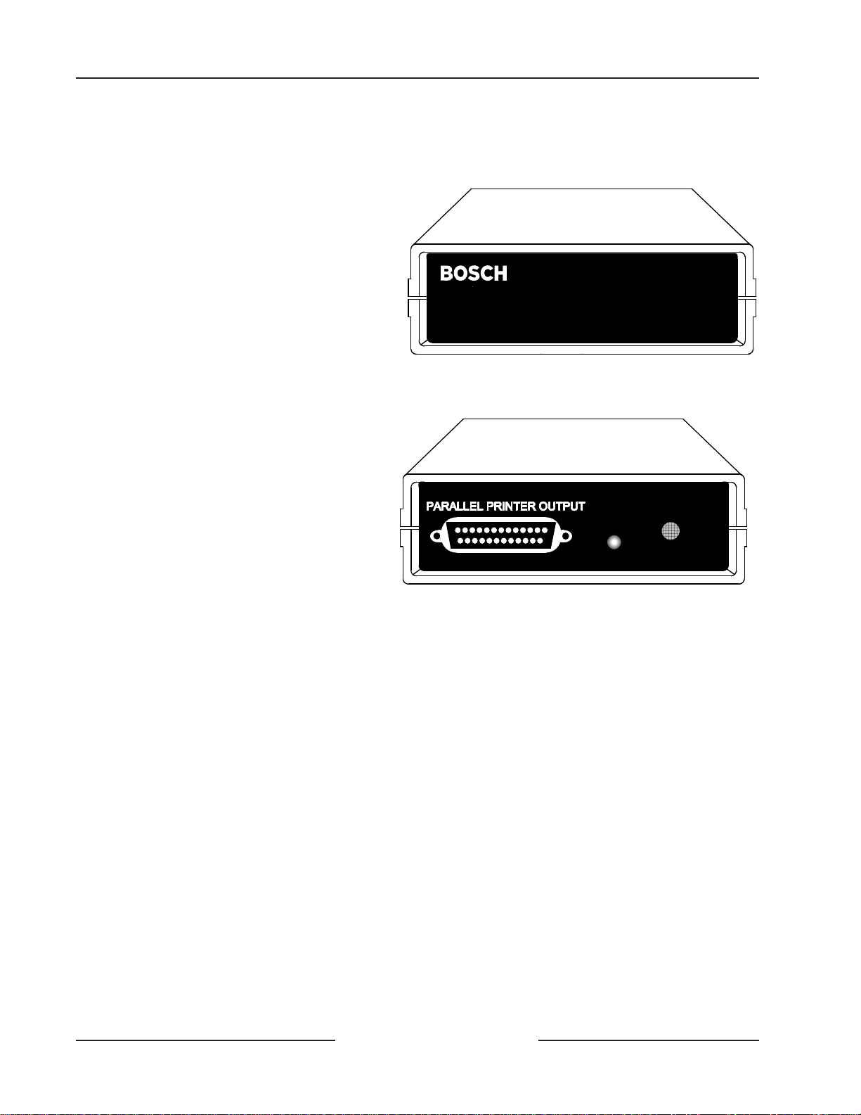
LED Indicators The green LED on the back of the D9131A indicates the
D9131A is being addressed by the control panel and the
D9131A has successfully decoded the information.
Printers Continuous-feed printers, such as dot matrix printers, are
recommended.
The D9131A is com patible only with the D9412GV2, D7412GV 2, D7212G V2, D9412G,
D7412G , D7212G, D9412, D9112, D7412, and D7212 Control Panels. It is not compatible
with the D 9112B1, D7212B1, or D 7112 Control Panels.
Only the D9412GV2 and D7412GV 2 are 9th Edition UL 864 listed panels. The D 9412G,
D7412G , D9412, D 9112, and D7412 are 8th Edition U L 864 listed control panels suitable
fo r re tro fit a p p lic a tio n s o n ly.
The ICP-SDI-9114 m odu le is required for Co m m ercial Fire applications. For wiring
requ iremen ts, refer to the ICP-SDI-9114 SDI Splitter Installation Guide (P/N:
F01U030068).
Fo r all ap p lications, install the D 9131 A in th e sa m e ro om as the p rinter.
Page 2
D9131A
3.0 Features
• Uses a standard parallel printer
• On-premises recording of D9412GV2,
D7412GV2, D7212GV2, D9412G, D7412G,
D7212G, D9412, D9112, D7412, and D7212
system events
• Simple four-wire installation
• Installation up to 305 m (1,000 ft) from the
control panel
• Complete event information including Date,
Time, Event, Account Number, Area
Number, User ID, Point Number, and Point
Te x t
• Three supervised D9131As and printers
supported by one D9412GV2/D9412G/
D9412/D9112. One supervised D9131A and
printer supported by the D7412GV2/
D7212GV2/D7412G/D7412/D7212G/D7212
• Programmable "Scope" allows the printer
to print a specific area's information, an
account's information, or panel-wide
information
• You can program the control panel to
report the following selected events: Fire
Events, Burglar Events, Access Events
(D9412GV2, D7412GV2, D9412G, D7412G,
D9412, D7412 only), User Events, Test Events, Diagnostic Events, Auto Function Events, RAM Events, Relay
Events, Point Events, User Change Events
SDI INPUT
DATA
Bosch Security Systems D9131A
D9131A Installation Guide
F01U135506-01 Page 2 © 2009 Bosch Security Systems, Inc.
Page 3

D9131A
4.0 Installation
4.1 Wiring the D9131A to the Control Panel
You can place the D9131A up to 305 m (1000 ft) from the panel.
Terminal Connections
D9131A Control Panel
SDI PWR 32
SDI-A 31
SDI-B 30
SDI COM 29
4.2 Connecting the D9131A to the Printer
Use a standard parallel printer cable. One end should be a Centronics connector, and the other a DB25 male connector. The
parallel printer connector on the D9131A is a DB25 female connector.
5.0 Switch Settings
Switches 1 and 2 in each D9131A determine its address. Switch 4 determines whether or not a form feed is provided and a
page header is printed. Switches 3, 5, and 6 are not used.
After changing switch settings, the D9131A must be powered off then back on, otherwise the change in switch settings has no
effect.
5.1 Printer Address
The address of each D9131A must match the corresponding address programmed in the control panel. See below for switch
settings for printers 17, 18 and 19. The D7412GV2, D7212GV2, D7412G, D7212G, D7412, and D7212 use address 17. The
D9412GV2, D9412G, D9412 and D9112 use addresses 17, 18, and 19.
Printer Address Switch Settings
Printer 17 1 and 2 ON
Printer 18 1 OFF, 2 ON
Printer 19 1 ON, 2 OFF
The first two switches determine the printer address.
5.2 Header and Form Feed
Switch 4 determines if a header and form feed are provided. Put switch 4 in the ON position to print the header and provide
a form feed.
Turn off the header and form feed feature if you are using a print spooling device to have multiple D9131A interfaces
connected to a single printer.
D9131A Installation Guide
© 2009 Bosch Security Systems, Inc. Page 3 F01U135506-01
Page 4

6.0 FCC Notice
Part 15
This equipment generates, uses, and can radiate radio frequency energy. If it is not installed and used in accordance with the
manufacturer's instructions, it may cause interference to radio and television reception. It has been tested and found to
comply with the specifications in Part 15 of FCC rules for Class B Computing Devices.
If this equipment causes interference to radio or television reception — which can be determined by turning the equipment
on and off — the installer is encouraged to correct the interference by one or more of the following measures: 1) Reorient the
antenna of the radio/television. 2) Connect the AC transformer to a different outlet so the control panel and radio/television
are on different branch circuits. 3) Relocate the control panel with respect to the radio/television.
If necessary, the installer should consult an experienced radio/television technician for additional suggestions, or send for the
"Interference Handbook" prepared by the Federal Communications Commission. This booklet is available from the U.S.
Government Printing Office, Washington D.C. 20402, stock number 004-000-00450-7.
© 2009 Bosch Security Systems, Inc. F01U135506-01 6/09
130 Perinton Parkway, Fairport, NY 14450-9199 USA Installation Guide D9131A
www.boschsecurity.com Page 4 of 4
 Loading...