

Page 1
D9112B
Program Entry Guide
EN
Control Panel
Page 2

D9112B | Program Entry Guide | EN | 2
Notice
The material and instructions covered in this manual
were carefully checked for accuracy and presumed to
be reliable. However, Bosch Security Systems assumes
no responsibility for inaccuracies and reserves the right
to modify and revise this manual without notice.
It is our goal at Bosch Security Systems to always
supply accurate and reliable documentation. If a
discrepancy is found in the documentation, please mail
a photocopy of the corrected material to:
Bosch Security Systems
130 Perinton Parkway
Fairport, NY 14450-9199 USA
Generally words shown in all capital letters indicate
command center displays, and command center keys.
For example, SERVC COMM FAIL is the command
center display for failure to communicate with the
D6500 receiver. ESC is a key on the command center.
Depending on the context of the sentence, all capital
letters can also indicate a recommended programming
selection.
About this Guide
This guide describes the parameters available to the
D9112B Control Panel. This guide follows the
organization of the D9112B product handler in the
D5200 Programmer.
Each programming section, program item, and its page
number is listed in the table of contents.
Throughout this guide, programming prompts are
shown in bold italic letters when used in a sentence. For
example, Phone 1 is the first programming prompt in
the Phone section of the program. References to
modules, categories, and sections of the program are
shown in italic letters. For example, Phone is the first
programming category in the Panel Wide Parameter
programming module.
Use the D9112B Program Record Training Sheet (P/N:
74-06447-000) to review default program entries as you
read this guide.
For a more complete understanding of the D9112B
Control Panel, read the following manuals in addition
to the Program Entry Guide:
•
D9112 Operation and Installation Manual
•
Security System Owners Manual
•
Security System User’s Guide
Other Lettering Conventions
Used in this Manual
D6500 reports are shown in bold italic letters. For
example,
the panel reports an AC power failure.
Bosch Security Systems | 2/04 | 74-06145-000-D
AC Failed
indicates the report sends when
Page 3

D9112B | Program Entry Guide | Contents EN | 3
1.5 RAM Parameters............................................ 22
Table of Contents
1.0 Panel Wide Parameter..................................8
1.1 Phone .................................................................8
Phone 1............................................................................8
Phone 2............................................................................9
Phone 3............................................................................9
Phone 4............................................................................9
Modem Format..............................................................9
Point/User Flag ...........................................................10
DTMF Dialing .............................................................11
Phone Supv Time .......................................................11
Alarm On Fail..............................................................11
Two Phone Lines ........................................................11
BFSK Duress Code .....................................................12
Expanded Test Rpt.....................................................12
Cancel Report .............................................................12
Ground Start................................................................12
1.2 Phone Routing ................................................12
Phone.............................................................................17
Ph# Fire Alarm/Res...................................................17
Ph# Tbl/Res .................................................................17
Ph# Alarm/Res/Cncl .................................................17
Ph# Trouble.................................................................17
Ph# Open/Close .........................................................17
Ph# Test/Stat Rpt .......................................................18
Ph# Diagnostic ............................................................18
Ph# Relay .....................................................................18
Ph# Skeds .....................................................................18
Ph# RAM......................................................................18
Ph# Power/Phone.......................................................18
Ph# Service..................................................................19
1.3 Power Supervision..........................................19
AC Fail Time ...............................................................19
AC Fail/Res Rpt..........................................................19
AC Tag Along..............................................................19
AC/Battery Buzz .........................................................19
Bat Fail/Res Rpt..........................................................20
1.4 Printer Parameters ..........................................20
Printer Address ...........................................................20
P## Scope ....................................................................20
P## Area Assign .........................................................21
P ## Supervision ........................................................21
P## Prt Points..............................................................21
P ## Prt O/C................................................................21
P## Prt Non Alrm ......................................................21
RAM Passcode ............................................................22
Log % Full ....................................................................22
RAM Call Back........................................................... 23
RAM Line Monitor .................................................... 23
Answer Armed............................................................ 23
Answer Disarmed ......................................................23
Ram Ph .........................................................................24
2.0 Area Wide Parameters............................... 25
2.1 Area Parameters............................................. 25
Area #........................................................................... 25
A# Area On.................................................................25
A# Acct Number ........................................................ 25
A# FA Bypass Max ....................................................25
A# Delay Res ..............................................................26
A# Exit Tone...............................................................26
A# Exit Dly Time.......................................................26
A# Auto Watch...........................................................26
A# Verify Time ..........................................................26
2.2 Bell Parameters............................................... 27
Area #........................................................................... 27
A# Fire Time............................................................... 27
A# Fire Pat................................................................... 28
A# Burg Time ............................................................. 28
A# Burg Pat................................................................. 28
A# Single Ring............................................................ 29
A# Bell Test.................................................................29
2.3 Opening and Closing..................................... 29
2.3.1 Open and Close Options .............................. 29
Area...............................................................................30
A# Acct O/C ...............................................................30
A# Area O/C ..............................................................31
A# Restricted O/C.....................................................32
A# Perimeter O/C..................................................... 33
A# Disable O/C in Window....................................33
A# Auto Close ............................................................34
A# Fail To Open ........................................................ 34
A# Fail To Close ........................................................34
2.4 O/C Windows................................................ 35
Window ........................................................................ 35
W## Sunday................................................................ 35
W## Monday.............................................................. 35
W## Tuesday..............................................................35
W## Wednesday........................................................ 35
W## Thursday............................................................36
W## Friday .................................................................36
W## Saturday............................................................. 36
Bosch Security Systems | 2/04 | 74-06145-000-D
Page 4

D9112B | Program Entry Guide | Contents EN | 4
W## Open Early Begin.............................................36
W## Open Window Start ........................................36
2.4.1 Programming Two Opening Windows
on the Same Day ............................................37
2.4.2 Programming to Link Two Days Over
Midnight ..........................................................37
W## Close Early Begin.............................................37
W## Close Window Start.........................................38
W## Close Window Stop.........................................38
W## Xept Holiday.....................................................39
2.4.3 Holiday Indexes for O/C Windows.............39
W## Holiday 1............................................................39
W## Holiday 2............................................................39
W## Holiday 3............................................................39
W## Holiday 4............................................................39
W## Area #.................................................................39
2.4.4 Opening/Closing Windows Worksheet.......40
2.5 Command Center...........................................42
2.5.1 Cmd Cntr Assignment ...................................42
Cmd Center #..............................................................42
CC# Supervised..........................................................42
CC# Scope ...................................................................42
CC# Area .....................................................................43
2.5.2 Area Text.........................................................43
Area ...............................................................................43
Area # Is On ................................................................43
Area # Not Ready.......................................................43
Area # Is Off ................................................................43
Area # Acct Is On.......................................................43
2.5.3 Custom Function ............................................44
Custom Function ###................................................44
CF### Text .................................................................44
CF### Key Strokes....................................................44
2.5.4 Programming Custom Function Keystrokes45
3.0 User Interface................................................45
3.1 Commands ......................................................45
3.2 Command Menu and Custom Functions ....45
3.3 Cmd Center Function ....................................46
3.4 Authority Lvl Assign......................................46
Disarm...........................................................................47
L## Disarm...................................................................47
Master Arm ..................................................................48
L## Master Arm...........................................................48
Mstr Arm Inst...............................................................49
L## Master Arm Inst...................................................50
Perim Instant................................................................50
L## Perim Inst..............................................................51
Perim Delay.................................................................51
L## Perim Delay .........................................................52
Watch Mode ................................................................ 53
L## Watch Mode ........................................................53
Perim Partial ...............................................................53
L## Perim Partial......................................................... 53
View Area Stat............................................................ 53
L## View Area Stat.....................................................53
View Event Mem........................................................ 53
L## View Event Mem ................................................ 53
View Pt Status ............................................................. 54
L## View Pt Stat.......................................................... 54
Walk Test ..................................................................... 54
L## Walk Test .............................................................54
Fire Test........................................................................ 54
L## Fire Test................................................................54
Send Report................................................................. 55
L## Send Report ......................................................... 55
Chg Display................................................................. 55
L## Chg Display .........................................................55
Chg Time/Date........................................................... 55
L## Chg Time/Date.................................................... 55
Chg Passcode............................................................... 55
L## Chg Passcode ....................................................... 55
Add Passcode ..............................................................56
L## Add Passcode.......................................................56
Del Passcode................................................................ 56
L## Del Passcode ........................................................ 56
Extend Close ............................................................... 56
L## Extend Close........................................................56
View Log......................................................................56
L## View Log.............................................................. 57
Print Log....................................................................... 57
L## Print Log...............................................................57
User Cmd 7.................................................................. 57
L## User Cmd 7..........................................................57
User Cmd 9.................................................................. 57
L## User Cmd 9..........................................................57
Bypass a Pt ................................................................... 58
L## Bypass a Pt ...........................................................58
Unbypass a Pt..............................................................58
L## Unbypass a Pt ...................................................... 58
Reset Sensors............................................................... 58
L## Reset Sensors .......................................................58
Relay Control..............................................................58
L## Relay Control....................................................... 58
Remote Program ........................................................ 58
Bosch Security Systems | 2/04 | 74-06145-000-D
Page 5

D9112B | Program Entry Guide | Contents EN | 5
L## Remote Program..................................................59
Move to Area...............................................................59
L## Move to Area........................................................59
Display Rev..................................................................59
L## Display Rev ..........................................................59
Service Walk................................................................59
L## Service Walk.........................................................60
Default Text .................................................................60
L## Default Text..........................................................60
Change Skeds ..............................................................60
L## Change Skeds .......................................................60
3.5 Authority Level Opening and Closing
Options ............................................................60
L## Force Arm.............................................................60
L## Area O/C..............................................................61
L## Restricted O/C.....................................................61
L## Perimeter O/C......................................................61
L## Send Duress..........................................................61
L## Passcode Arm.......................................................62
L## Passcode Disarm ..................................................62
4.0 Command Menu...........................................62
Menu Item ....................................................................62
M## Function..............................................................62
M## CC Address 1.....................................................63
M## CC Address 2.....................................................63
M## CC Address 3.....................................................63
M## CC Address 4.....................................................63
M## CC Address 5.....................................................63
M## CC Address 6.....................................................63
M## CC Address 7.....................................................63
M## CC Address 8.....................................................63
5.0 User Access Windows..................................64
User Window # ...........................................................64
UW## Sunday.............................................................64
UW## Monday ...........................................................64
UW## Tuesday ...........................................................64
UW## Wednesday .....................................................64
UW## Thursday .........................................................64
UW## Friday...............................................................64
UW## Saturday ..........................................................64
UW## Access Window Start....................................64
UW## Access Window Stop....................................64
5.1 Holiday Indexes for User Access Windows65
UW## Xept Holiday..................................................65
UW## Holiday 1.........................................................65
UW## Holiday 2.........................................................65
UW## Holiday 3.........................................................65
UW## Holiday 4 ........................................................ 65
6.0 Passcode Worksheet.................................... 66
Duress ...........................................................................66
User ...............................................................................67
U## Passcode..............................................................67
U## User Window.....................................................67
U## Area 1 Auth........................................................ 68
U## Area 2 Auth........................................................ 68
U## Area 3 Auth........................................................ 68
U## Area 4 Auth........................................................ 68
U## Area 5 Auth........................................................ 68
U## Area 6 Auth........................................................ 68
U## Area 7 Auth........................................................ 68
U## Area 8 Auth........................................................ 68
7.0 Point Index....................................................69
Point Index #............................................................... 69
P## Type...................................................................... 69
P## Pt Response......................................................... 72
P## Entry Delay.........................................................73
P## Entry Tone Off................................................... 73
P## Silent Bell............................................................ 73
P## Ring Until Restored.......................................... 73
P## Audible After 2 Failures .................................. 74
P## Invisible............................................................... 74
P## Buz on Fault........................................................74
P## Watch Point ........................................................74
P## Relay Follows Point .......................................... 75
P## Local While Disarmed ..................................... 75
P## Local While Armed ..........................................76
P## Disable Restorals...............................................76
P## Returnable .......................................................... 76
P## Bypassable........................................................... 77
P## Swinger Bypass.................................................. 77
P## Report Bypass at Occurrence.........................77
P## Defer Bypass Report......................................... 78
P## Fire Point.............................................................78
P## Alarm Verify ......................................................78
P## Resettable............................................................ 78
8.0 Point Assignments ....................................... 79
8.1 Point Assignments..........................................79
Point Number.............................................................. 79
P## Point Index.......................................................... 79
P### Area Assign......................................................79
P### Debounce.......................................................... 79
P### BFSK/Relay...................................................... 79
P### Point Text......................................................... 80
8.2 Command 9....................................................80
Bosch Security Systems | 2/04 | 74-06145-000-D
Page 6

D9112B | Program Entry Guide | Contents EN | 6
Point Index...................................................................80
BFSK Code...................................................................80
Point Text .....................................................................81
8.3 Command 7 ....................................................81
Point Index...................................................................81
BFSK Code...................................................................81
Point Text .....................................................................81
9.0 Relay Parameters .........................................82
9.1 Area Wide Relays...........................................83
Area ...............................................................................83
A# Alarm Bell .............................................................83
A# Fire Bell..................................................................83
A# Reset Sensors ........................................................83
A# Late To Close........................................................83
A# Force Armed.........................................................84
A# Watch Mode..........................................................84
A# Area Armed ..........................................................84
A# Area Fault..............................................................84
A# Duress.....................................................................84
A# Keypad Fail...........................................................84
S## Friday ................................................................... 93
S## Saturday............................................................... 93
S## Xept Holiday ...................................................... 93
S## Holiday 1 ............................................................. 93
S## Holiday 2 ............................................................. 93
S## Holiday 3 ............................................................. 93
S## Holiday 4 ............................................................. 94
11.0 Holiday Indexes...........................................94
11.1 Add/Change/Delete ...................................... 94
Date ............................................................................... 94
Holiday Index 1.......................................................... 94
Holiday Index 2.......................................................... 95
Holiday Index 3.......................................................... 95
Holiday Index 4.......................................................... 95
11.2 View Holidays................................................95
Index 1 Days................................................................ 95
Index 2 Days................................................................ 95
Index 3 Days................................................................ 95
Index 4 Days................................................................ 95
A# Perim Fault............................................................84
A# Silent Alarm..........................................................84
A# Command 7...........................................................85
A# Command 9...........................................................85
9.2 Panel Wide Relays..........................................85
Printer 17 Fail ..............................................................85
Printer 18 Fail ..............................................................85
Printer 19 Fail ..............................................................85
AC Failure....................................................................85
Battery Trouble...........................................................85
Phone Fail.....................................................................85
Comm Fail....................................................................85
Log % Full.....................................................................86
Summary Fire..............................................................86
Summary Alarm..........................................................86
Summary Fire Tbl.......................................................86
Summary Trouble.......................................................86
10.0 Skeds ...............................................................86
Sked Number...............................................................86
S## Function Code ....................................................87
S## Time......................................................................92
S## Date.......................................................................92
S## Sunday..................................................................92
S## Monday ................................................................93
S## Tuesday ................................................................93
S## Wednesday ..........................................................93
S## Thursday ..............................................................93
Bosch Security Systems | 2/04 | 74-06145-000-D
Page 7

D9112B | Program Entry Guide | Contents EN | 7
Table of Tables
Table 1: Modem II Communication Format Data –
User ID Numbers (Point/User Flag)..............10
Table 2: Modem II Communication Format Data –
Point Numbers (Point/User Flag)...................10
Table 3: Phone Routing ...............................................13
Table 4: Phone Routing Worksheet – Fire Alarm/Res
(Fire Alarm/Restoral)....................................13
Table 5: Phone Routing Worksheet – Fire Tbl/Res
(Fire Trouble/Restoral).................................13
Table 6: Phone Routing Worksheet – Alarm/ Res/Cncl
(Non-Fire Alarm/Restoral/ Cancel)............14
Table 7: Phone Routing Worksheet – Trouble (Non-
Fire Trouble)..................................................14
Table 8: Phone Routing Worksheet – Diagnostics ...14
Table 9: Phone Routing Worksheet –Relay ..............14
Table 10: Phone Routing Worksheet – Open/Close15
Table 11: Phone Routing Worksheet – Skeds...........15
Table 12: Phone Routing Worksheet – Test/Stat Rpt
(Test and Status Reports)............................16
Table 13: Phone Routing Worksheet – RAM ...........16
Table 14: Phone Routing Worksheet – Power/Phone17
Table 15: Phone Routing Worksheet – Service ........17
Table 16: Verify Time Examples................................27
Table 17: Programming for Two Opening Windows on
the Same Day ..............................................37
Table 18: Programming to Link Two Days Over
Midnight.......................................................37
Table 19: W# Close Window Stop Programming
Example .......................................................38
Table 20: Opening/Closing Windows Worksheet....40
Table 21: Opening/Closing Windows........................40
Table 22: Normal Store Hours* ..................................41
Table 23: Delivery Schedule*......................................41
Table 24: Monthly Auditor’s Schedule*.....................41
Table 25: CF## Keystrokes ........................................44
Table 26: CF## Custom Function Keystrokes .........45
Table 27: Command Center Function Selections.....46
Table 28: Authority Level Selections .........................47
Table 29: BFSK User ID Report Format ...................66
Table 30: Point Response Table .................................72
Table 31: BFSK/Relay Codes .....................................80
Table 32: Relay Status..................................................82
Bosch Security Systems | 2/04 | 74-06145-000-D
Page 8
D9112B | Program Entry Guide | 1.0 Panel Wide Parameter EN | 8
A Comm Restoral event generates after another
1.0 Panel Wide Parameter
Use this programming module to define the operating
characteristics that affect panel-wide functions. This
module has five categories:
• Phone Operation
• Phone Routing
• Power Supervision
reporting event successfully transmits to any of the
receiver phone numbers. This
is sent according to the routing for
Phone Routing. When you receive a
report, use RAM to download the event log to
determine which events did not send, and which phone
number(s) failed. Receiving the
does not mean that all phone lines are restored, only
that at least one phone line operates.
Comm Restoral
Power/Phone
Comm Restoral
Comm Restoral
report
in
report
• Printer Parameters
• Remote Account Manager (RAM) Parameters
1.1 Phone
The D9112 can dial up to four different telephone
numbers when sending event reports. The program
items in this category describe panel wide
characteristics for telephone dialing, receiver format,
and supervision. All telephone numbers use the same
receiver format.
Communications Failure: When only a primary
phone destination is programmed for a report (see
Phone Routing), the D9112 generates a communication
failure (Comm Fail) event if the panel does not reach
the receiver:
• After ten attempts if the panel contains software
revision 2.93 or lower.
• After five attempts if the panel contains software
revision 2.94 or higher.
When both primary and backup phone destinations are
programmed for a report, the panel alternates between
the primary destination and the backup destination.
• If the panel is equipped with software revision 2.93
or lower, it makes a total of 20 attempts (ten to
each phone destination).
Phone 1
Phone 1 is the telephone number the D9112 dials to
contact the central station receiver when sending event
reports (see Phone Routing).
The D9112 is preprogrammed with a seven sec. dial
tone detect period. When a dial tone is detected or the
waiting period ends, the D9112 begins to dial. To
extend the dial tone detect, program a D before the
phone number. To insert a pause during or after
dialing, use C in the number sequence. For example, if
the D9112 hangs up before it hears a Modem II ack
tone from the D6500, it programs extra Cs after the
phone number. The D9112 waits on the line for three
extra seconds for each C programmed.
Enter up to 24 of the characters in the following table
to define dialing characteristics:
0101
0101
0101
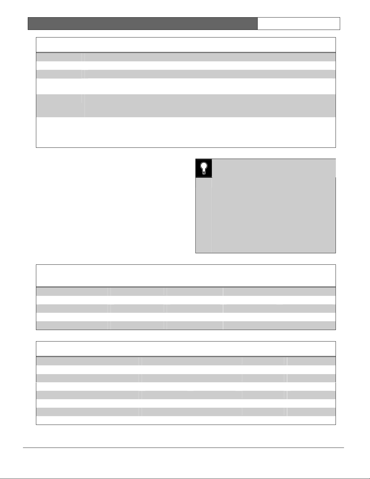
Using both phone data entry lines: The first
line of the phone number data entry line
must be filled (12 characters) before
pressing the [ENT] key to move on to the
second line. If you enter characters on the
second line, and there are less than twelve
characters on the first line, the second line
clears when you press [ENT].
• If the panel is equipped with software revision 2.94
or higher, it makes a total of ten attempts (six to
the primary and four to the backup).
• If these attempts fail, the D9112 generates a Comm
Fail event.
A Comm Fail event appears at the command center as
SERV COMM FAIL. A Comm Fail event is placed in
the event log if Comm Fail occurs on both the primary
and backup phones. Comm Fail does not report to the
D6500 except during
Expand Test Rpt
Bosch Security Systems | 2/04 | 74-06145-000-D
Test
YES).
reports (You must program
Page 9

D9112B | Program Entry Guide | 1.0 Panel Wide Parameter EN | 9
Default: Blank
Selection:
0 - 9
C
D
Up to 24 characters (do not enter [SPACE])
Numbers zero through nine
3 sec. pause
7 sec. dial-tone detect.
The same as pressing this key on a telephone keypad when manually dialing. For example, you may
need an asterisk (*) to access your long distance service. Do not use these characters when pulse
# or *
dialing.
Panel dials no phone number.
Programming this item Blank does not disable phone routing. To disable reporting to this phone see
Blank
Phone Routing.
Phone 2
Default: Blank
Selection: Up to 24 characters (do not enter
[SPACE])
(See explanation of Phone 1.) This number is
“Phone 3,” referenced in Phone Routing Parameters.
Phone 3
Default: Blank
(See explanation of Phone 1.) This number is
“Phone 3,” referenced in Phone Routing Parameters.
Phone 4
Default: Blank
Selection:
Up to 24 characters (do not enter
[SPACE])
(See explanation of Phone 1.) This number is
“Phone 4,” referenced in Phone Routing Parameters.
Selection Up to 24 characters (do not enter
[SPACE])
Modem Format
The central station receiver format for transmitting reports,
Modem Format
provides many reporting advantages
over the BSFK format (see the D6500 Report Directory for more information about the effect of reporting
formats).
Default: Yes
Selection Yes or No
Yes
Modem II (requires Bosch Security Systems D6500 Receiver with MPU EPROM version 6.00 or
higher and Line EPROM version 6.00 or higher)
Modem II format reports identify points as 001 through 135 and passcode User ID codes as 00
through 99 at the D6500 receiver (unless
Point/User Flag
is programmed YES, see the next prompt).
When reporting point events, Modem II also sends point text to the D6500 as programmed in Point
Assignments.
No
BFSK (2300 Hz or 1400 Hz acknowledgment tone).
Basic reporting functions are available, but reporting options are limited to account opening and
closing (see
in Point Assignments
A# Acct O/C
P### BFSK/Relay
and
A# Area O/C
), users are identified by only one digit as programmed
.
Bosch Security Systems | 2/04 | 74-06145-000-D
Page 10
D9112B | Program Entry Guide | 1.0 Panel Wide Parameter EN | 10
Point/User Flag
This program item determines how point and User
ID numbers are presented at the D6500 display,
printer, and computer RS-232 output.
When
Modem Format
is YES, the D9112 sends
expanded Modem II reports to the D6500. If your
central station data files are not set up for D9112
point and User ID number reporting, you can use
When
Modem Format
is YES, the D9112 sends
expanded Modem II reports to the receiver.
Point/User Flag affects Modem II data as shown in
the following table. The leading zero in the User ID
Number with Point/User Flag programmed NO is
added by the Bosch Security Systems D6500
Receiver.
this program item to convert these numbers to
D8112 style ZONEX and COMEX reports.
Default: Yes
Selection: Yes or No
Yes
The D9112 sends a “flag” with each report telling the D6500 to convert D9112 point numbers to
D8112 style ZONEX format and User ID numbers to D8112 style COMEX format. The conversions
are shown in Table 1 and Table 2. [No matter how the D6500 is programmed for output to the
computer system, points and User ID numbers are converted when this item is YES. (See the
D6500:MPU Program Entry Guide, CompOut program item.)]
No
The D9112 does not send the “flag.” The D6500 outputs point numbers as 001 to 135 (rather than
100 to 815) and User ID numbers as 000 to 099 (rather than 000 to F08), as indicated in Table 1 and
Table 2.
Table 1: Modem II Communication Format Data –
User ID Numbers (Point/User Flag)
No Yes
000 000
001 to 005 001 to 005
006 to 013 601 to 608
014 to 021 701 to 708
022 to 029 801 to 808
030 to 037 B01 to B08
038 to 045 C01 to C08
046 to 053 D01 to D08
054 to 061 E01 to E08
062 to 069 F01 to F08
070 to 099 000
Independent Zone Control Notice:
When using
Independent Zone Controls (I.Z.C.) to send
Opening/Closing
reports by point, do not duplicate
reporting independent point numbers with User ID
reports (see Passcode Worksheet). For example: If an
I.Z.C. is connected to point 8, User ID 8 should not
be used.
Table 2: Modem II Communication Format Data –
Point Numbers (Point/User Flag)
No Yes
001 to 008 100 to 800
009 to 024 101 to 116
025 to 040 201 to 216
041 to 056 301 to 316
057 to 071 401 to 415
073 to 088 501 to 516
089 to 104 601 to 616
105 to 120 701 to 716
121 to 135 801 to 816
D6000: Opening/Closing User ID numbers are
identified at the receiver as "ZONEs" (same
identification as independent points).
User ID 1 = ZONE B
User ID 2 = ZONE C
User ID 3 = ZONE D
User ID 4 = ZONE E
Bosch Security Systems | 2/04 | 74-06145-000-D
Page 11
D9112B | Program Entry Guide | 1.0 Panel Wide Parameter EN | 11
User ID 5 = ZONE F
User ID 6 = ZONE 6
User ID 7 = ZONE 7
User ID 8 = ZONE 8
User ID 91 = ZONE 1
User ID 92 = ZONE 2
User ID 93 = ZONE 3
User ID 94 = ZONE 4
User ID 95 = ZONE 5
User ID 96 = ZONE 0
COMMAND 1 = ZONE 9 (only closing)
D6500 Receiving BFSK Format: Opening/closing
User ID numbers are identified at the receiver as ZN
(same identification as independent points). The ZN
numbers are based on the “tens” digit of the User ID
number.
DTMF Dialing
Use DTMF (dual-tone multi-frequency) to dial the
central station receiver phone number(s) for event
reports, and/or the D5300 Remote Account
Manager.
Default:
Yes
Selection: Yes or No
Yes
Dials the programmed phone
number(s) using DTMF.
No
Pulse dialing only
Phone line trouble responses:
Command centers display SERVC PH LINE # and
sound the trouble tone.
Restoral
reports identify the previously failed line
after it restores when a single phone line is used, if
Power/Phone
is enabled in Phone Routing.
Trouble and restoral events are reported if
Power/Phone
is enabled in Phone Routing, a Dual
Phone Line Module is installed, and one of the
phone lines is operational.
Alarm On Fail
Default: Yes
Selection: Yes or No
Yes
Generate alarm responses in Area 1
and trouble responses in all other areas
when a phone line fails.
Time
must be programmed to use this
Phone Supv
feature.
Phone Failure Alarm Responses: An
alarm tone sounds at command centers
assigned to Area 1. The alarm bell
relay for Area 1 activates. The
Fail
relay activates if programmed in
Phone
Relay Parameters.
No
Trouble responses when a phone line
fails.
Phone Supv Time
must be
programmed to use this feature.
Two Phone Lines
Phone Supv Time
Sets the amount of time the panel continues to
monitor a faulted phone line before initiating phone
line trouble responses.
Default: Blank
Selection: Blank or 10 to 240
Blank
10 to 240
No phone line supervision.
Initiate phone line trouble response if
the phone line continues to be faulted
after the programmed amount of
seconds expire. After a faulted phone
line restores, it takes the same amount
of time to initiate restoral responses.
Make settings in ten sec. increments.
Bosch Security Systems | 2/04 | 74-06145-000-D
Use when a Dual Phone Line Module is connected
to the D9112. Both lines must operate the same,
either ground start or loop start. NFPA standards
prohibit the use of ground start phone lines in
systems monitoring fire points.
Default: No
Selection: Yes or No
Yes
Dual Phone Line Module installed.
The LEDs on the module light to
indicate primary or secondary line
trouble and Comm Fail.
No
No Dual Phone Line Module.
0101
0101
0101
IMPORTANT! Program Phone Supv Time
when using two phone lines.
Page 12

D9112B | Program Entry Guide | 1.0 Panel Wide Parameter EN | 12
BFSK Duress Code
Default: 0
Selection: 0 to 9
When transmitting in BFSK (
programmed NO), you must assign a number to
identify
is enabled in Duress in the Passcode Worksheet.
Expanded Test Rpt
Use to add system event information to scheduled
Test
events in the Skeds Parameters section of the program.
Default: No
Selection: Yes or No
Yes
No
Cancel Report
Use to control whether or not
sent.
A
entered to silence an Alarm Bell or Fire Bell before
the bell time expires. The cancel event is stored in
the panel’s event log, and sent to local printers as a
point event.
Use
section of the program to program bell times.
Program Alarm and Fire Bell relay outputs in Relays.
Default: Yes
Selection: Yes or No
Yes
No
Duress
reports.
Cancel
report is created when a passcode is
Burg Time
reports at the central station. Duress
Test
reports are set up as scheduled
Test
report includes the following
system events if the panel is currently in
the condition listed: Log Threshold, Log
Overflow, Point Bus Failure, Successful
Local Programming, Bad Call to RAM,
User Code Tamper, SDI Failure,
Communications Failure, AC Failure,
Battery Missing, Battery Low, Parameter
Bad Checksum.
Do not send system event information
Test
with
and
Fire Time
Send
Cancel
Phone Routing.
Do not send
phone(s).
Modem Format
reports.
Cancel
in the Bell Parameters
reports according to
Cancel
reports to the
is
reports are
Ground Start
Use only when the panel is connected to Ground
Start telephone lines.
Some newer ground start telephone exchange
switches require a shorter amount of time to initiate
a dial tone. If the panel cannot initiate a dial tone on
the ground start line with the default (Long) setting,
try the Short setting.
Both lines must be of the same operation, either
ground start or loop start. NFPA standards prohibit
the use of ground start phone lines in systems
monitoring fire points.
Default: Long
Selection: Short or Long
Long
Short
Standard duration of ground. Use
this setting for most ground start
telephone systems. The duration is
700 ms.
Shorter duration of ground. Use this
setting for telephone systems where
specified. The duration is 250 ms.
1.2 Phone Routing
Phone Routing lets you direct groups of event
reports to four different telephone numbers. The
phone numbers and operating characteristics are
programmed in the previous category Phone.
Fire alarm events have priority over all other events
that must be reported. An event that was not
reported to the primary or backup phone has a
higher priority than an event that needs to be
reported to a duplicate phone.
Event report groups that you do not send to the
central station may be annunciated locally (at the
command centers), printed on a local printer (D9131
required), or retrieved later by the Remote Account
Manager (RAM).
Each of the Report Groups can be programmed to
report to one or more of the phone numbers. The
phones can be used as primary, backup, or duplicate
reporting paths for each of the Report Groups.
Bosch Security Systems | 2/04 | 74-06145-000-D
Page 13
D9112B | Program Entry Guide | 1.0 Panel Wide Parameter EN | 13
Table 3: Phone Routing
Report Group Description
Blank
Not reported to this phone number.
P Primary: Send all reports from this group to this phone number. Only one primary phone
allowed per group.
B Backup: Send reports from this group to this phone if the report is not received by the primary
phone number. A primary phone route must also be programmed for this Report Group in order
to dial the backup phone number. Only one backup phone allowed per group.
D Duplicate: Send all reports from this group to this phone number after they are sent to the
other phone (primary or backup). A primary phone route must be programmed in order to send
a duplicate report. Only one duplicate phone allowed per group. Failure to send a duplicate
report does not generate any user notification or central station report.
Press the [SPACE] bar to scroll through the
selections. Press [ENT] when the correct selection
appears in the display.
0101
0101
0101
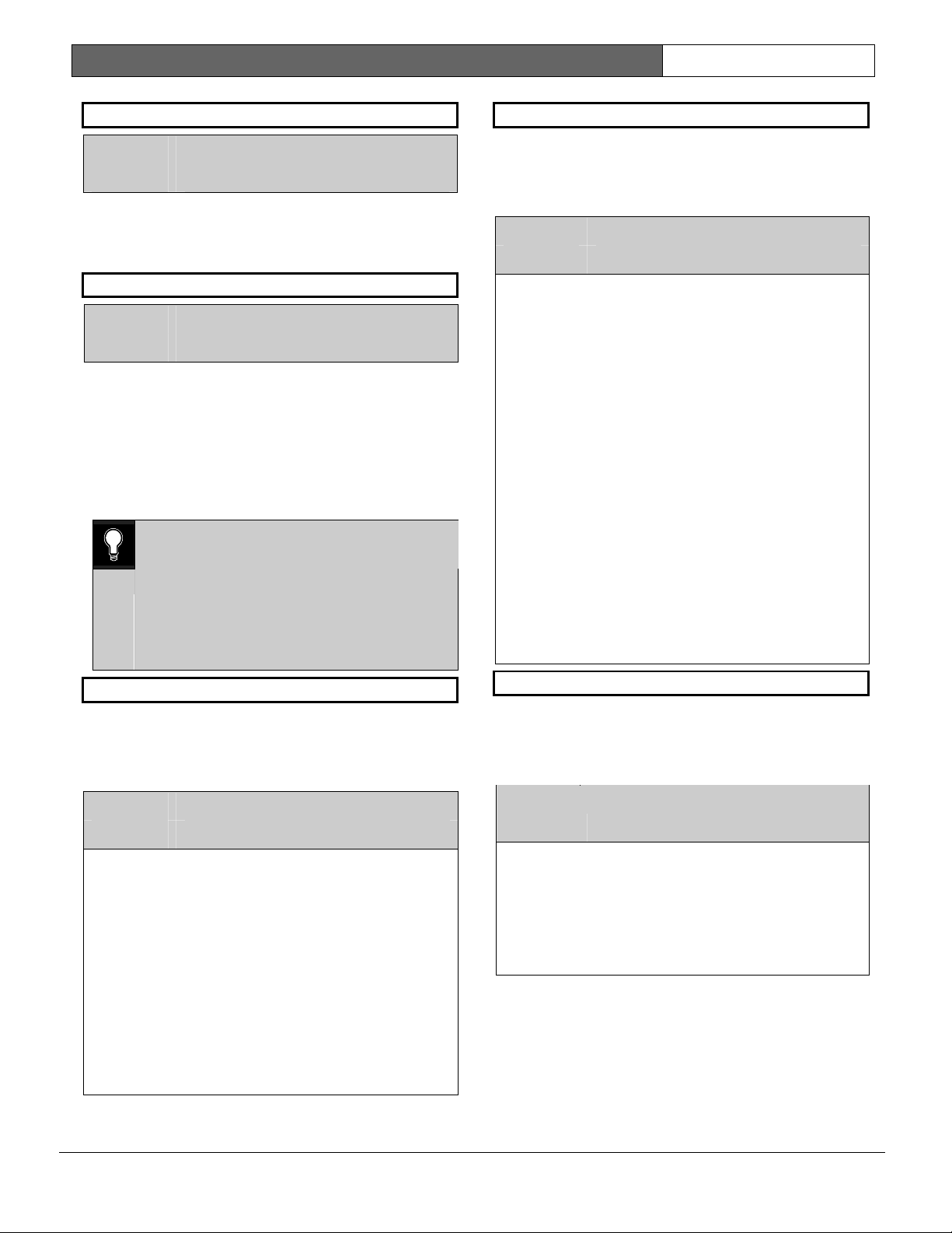
If the D5200 buzzes when you make an
entry, you made a routing error. If you enter
the same route on two different phones for
a particular Report Group the D5200
buzzes. When it buzzes, it accepts the entry
currently in the display, and changes the
matching routing entry to blank. This
disables routing the Report Group to the
other phone.
Recheck the phone routing for the Report
Group for each phone if the programmer
buzzes.
Table 4: Phone Routing Worksheet – Fire
Alarm/Res (Fire Alarm/Restoral)
Report Type Phone 1 Phone 2 Phone 3 Phone 4
Fire Alarm
Fire Restoral (after alarm)
x x
x x
Table 5: Phone Routing Worksheet – Fire Tbl/Res (Fire Trouble/Restoral)
Report Type Phone 1 Phone 2 Phone 3 Phone 4
Fire Trouble
Fire Walk Start
Missing Fire
Fire Restoral (after Trouble or Missing)
Fire Walk End
x x
x x
x x
x x
Bosch Security Systems | 2/04 | 74-06145-000-D
Page 14

D9112B | Program Entry Guide | 1.0 Panel Wide Parameter EN | 14
Table 6: Phone Routing Worksheet – Alarm/
Res/Cncl (Non-Fire Alarm/Restoral/
Cancel)
Report Type Phone 1 Phone 2 Phone 3 Phone 4
Alarm Report
User Alarm CMD 9
Restoral Report
Duress
User Code Tamper
Missing Alarm
User Alarm CMD 7
Cancel Alarm
x x
x x
x x
x x
x x
x x
Table 7: Phone Routing Worksheet – Trouble (Non-Fire Trouble)
Report Type Phone 1 Phone 2 Phone 3 Phone 4
Fire Trouble
Fire Walk Start
Missing Fire
Fire Restoral (after Trouble or Missing)
x x
x x
x x
x x
Table 8: Phone Routing Worksheet – Diagnostics
Report Type Phone 1 Phone 2 Phone 3 Phone 4
SDI Failure
Parm Cksum Fail
SDI Restoral
Re-boot
Watchdog Reset
Table 9: Phone Routing Worksheet –Relay
Report Type Phone 1 Phone 2 Phone 3 Phone 4
Sensor Reset
Relay Set
Relay Reset
x x
x x
Bosch Security Systems | 2/04 | 74-06145-000-D
Page 15

D9112B | Program Entry Guide | 1.0 Panel Wide Parameter EN | 15
Table 10: Phone Routing Worksheet – Open/Close
Report Type Phone 1 Phone 2 Phone 3 Phone 4
Point Opening
Late to Open
Closing Early
Extn Close Time
Perim Dlay Armed
F Close Early
F Close Pr Dlay
Command Bypass
Swinger Bypass
Early to Open
Fail to Open
Closing Late
Fail to Close
Was Force Armed
F Close Late
Forced Point
Sked Bypass
Opening Report
Point Closing
Closing Report
Perim Inst Armed
Forced Close
F Close Pr Inst
Point Bypass
RAM Bypass
x x
x x
x x
x x
x x
x x
x x
x x
x x
x x
x x
x x
x x
x x
x x
x x
x x
x x
x x
Table 11: Phone Routing Worksheet – Skeds
Report Type Phone 1 Phone 2 Phone 3 Phone 4
Sked Executed
Sked Changed
Bosch Security Systems | 2/04 | 74-06145-000-D
Page 16

D9112B | Program Entry Guide | 1.0 Panel Wide Parameter EN | 16
Table 12: Phone Routing Worksheet – Test/Stat Rpt (Test and Status Reports)
Report Type Sub Group Phone 1 Phone 2 Phone 3 Phone 4
Test Report (Includes
expanded panel wide
events as shown)
Status Report (includes
area events as shown)
Log Threshold
Prog Access OK
SDI Failure
Battery Missing
Pt Bus Trouble
AC Failure
Log Overflow
Bad Call to RAM
Comm Failure
Battery Low
User Tamper
Params Bad Cksm
S: Alarm
S: Opening
S: Perim Delay
Point Bypass
S: Trouble
S: Closing
S: Perim Instant
Forced Point
Table 13: Phone Routing Worksheet – RAM
Report Type Phone 1 Phone 2 Phone 3 Phone 4
Log Threshold
Bad Call to RAM
RAM Access OK
Parameters Changed
RAM Access Fail
Remote Reset
Bosch Security Systems | 2/04 | 74-06145-000-D
Page 17

D9112B | Program Entry Guide | 1.0 Panel Wide Parameter EN | 17
Table 14: Phone Routing Worksheet – Power/Phone
Report Type Phone 1 Phone 2 Phone 3 Phone 4
Comm Restoral
AC Failure
Battery Low
Phone Line Fail
AC Restoral
Battery Restore
Phone Restoral
Battery Missing
x x
x x
x x
x x
x x
x x
Table 15: Phone Routing Worksheet – Service
Report Type Phone 1 Phone 2 Phone 3 Phone 4
Usr Code Change
Prog Access Bad
Usr Code Delete
Date Change
Prog Access OK
Time Change
x x
x x
x x
x x
x x
x x
Phone
Default: 1
Selection: 1 to 4
Enter the phone’s number for which you are
selecting report group routing.
Ph# Fire Alarm/Res
Default: Blank
Selection: Blank, P, B, or D
See the introduction to Phone Routing for a
description of the selections.
Ph# Tbl/Res
Default: Blank
Selection: Blank, P, B, or D
See the introduction to Phone Routing for a
description of the selections.
Ph# Alarm/Res/Cncl
Default: Blank
Selection: Blank, P, B, or D
See the introduction to Phone Routing for a
description of the selections.
Ph# Trouble
Default: Blank
Selection: Blank, P, B, or D
See the introduction to Phone Routing for a
description of the selections.
Ph# Open/Close
Default: Blank
Selection: Blank, P, B, or D
See the introduction to Phone Routing for a
description of the selections.
Bosch Security Systems | 2/04 | 74-06145-000-D
Page 18

D9112B | Program Entry Guide | 1.0 Panel Wide Parameter EN | 18
Ph# Test/Stat Rpt
Default: Blank
Selection: Blank, P, B, or D
See the introduction to Phone Routing for a
description of the selections.
Test
reports and
Skeds section of the program. For
Sked Function Code #9. For
Sked Function Code #10.
Test
and
Status
using the account number for Area 1.
If
Expand Test Rpt
includes additional system events, if the panel is
currently in one of these conditions: Prog Access
OK, SDI Failure, Comm Failure, Battery
Missing, Battery Low, Pt Bus Trouble,
AC Failure, Params Bad Cksm, Log
Threshold, Log Overflow, Bad Call to
RAM, and User Tamper.
After a Reset-Bye or disable restart, the panel
checks to see if the following conditions exist. If they
do, the panel sends appropriate reports with the test
report:
to RAM
are cleared and do not report at test time.
To clear Bad Call to RAM and User Tamper
events, simply contact the panel with RAM II. To
clear Log Threshold and Log Overflow
contact the panel with RAM II and perform a
Receive Log and Set Pointer function from the
Logger menu.
Ph# Diagnostic
Default: Blank
Selection: Blank, P, B, or D
See the introduction to Phone Routing for a
description of the selections.
If a Parameter Checksum Fail (
report is received, the user can silence the panel’s
buzzer, but cannot clear the system trouble display.
To correct a Parameter Checksum Fail condition, reload the program into the panel using RAM or the
D5200
Log Threshold, Log Overflow, Bad Call
, and
Status
reports are enabled in the
Test
reports, see
Status
reports, see
reports are identified at the D6500
in Phone is YES, the
User Tamper
. All other system events
Test
report
Parm Cksum Fail
)
Ph# Relay
Default: Blank
Selection: Blank, P, B, or D
See the introduction to Phone Routing for a
description of the selections.
Ph# Skeds
Default: Blank
Selection: Blank, P, B, or D
See the introduction to Phone Routing for a
description of the selections.
Note:
The panel uses Skeds 18 to 49 for opening and closing
windows and Skeds 50 to 64 for User Access
Windows. Routing Skeds activity to a receiver when
using these features can result in excessive receiver
traffic.
Ph# RAM
Default: Blank
Selection: Blank, P, B, or D
See the introduction to Phone Routing for a
description of the selections.
These events are associated with RAM functions.
RAM reports are identified at the D6500 using the
account number for Area 1.
RAM Access Fail may indicate a wrong
passcode when communicating with the panel, or a
valid RAM session was terminated by a means other
than a Good-bye or Reset-bye command. Log
Threshold is programmed in RAM Parameters
. Remote Reset indicates a Reset-Bye
% Full
command issued from RAM. Bad Call to RAM
indicates that the panel called RAM but was unable
to connect.
Ph# Power/Phone
Default: Blank
Selection: Blank, P, B, or D
See the introduction to Phone Routing for a
description of the selections.
Log
Bosch Security Systems | 2/04 | 74-06145-000-D
Page 19
D9112B | Program Entry Guide | 1.0 Panel Wide Parameter EN | 19
Ph# Service
Default: Blank
Selection: Blank, P, B, or D
See the introduction to Phone Routing for a
description of the selections.
1.3 Power Supervision
AC Fail Time
Default: 10
Selection: 1 to 90 sec. (Blank and 0 are invalid)
Amount of time (in seconds) that AC power must be
off before the D9112 responds to the AC failure.
The response to restoral of AC power is delayed for
the same amount of time. The panel always monitors
AC. To disable audible and reporting failure
responses, program the following items NO:
Fail/Res Rpt, AC Tag Along
Buzz
.
0101
0101
0101
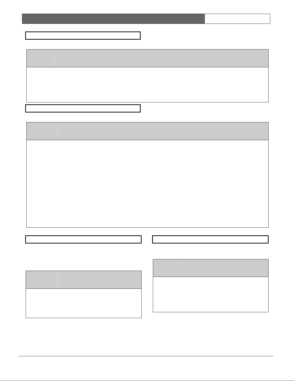
Visual AC Failure Response: When a
failure occurs, the SERVC AC FAIL
message displays at command centers.
You can program other AC failure
responses in the program items that follow,
and you can program a relay to activate in
Relay Parameters.
, and
AC/Battery
AC
,
AC Tag Along
Send
AC Failure
(tag along) with other reports. To comply with UL
864 requirements for Commercial Fire Systems,
program
Default: No
Selection: Yes or No
Yes When AC fails, the report is not sent
No
AC Tag Along
report as an additional message
YES.
until another event occurs. The
Fail
report is sent to the receiver with
subsequent event reports until the
Restoral
reports are routed to the phone
destination of the event with which it is
sent. If AC power restores before any
other event occurs, the report is not
sent.
Note:
AC Fail
events.
report is sent. These
If both
AC Fail/Res Rpt
Tag Along
Failure
Power/Phone
once as the primary message, and once
as the “tag along” report.
reports are not tag along
are YES, two
reports are sent to the
telephone number(s),
AC
AC Fail
and
AC
AC
AC
AC Fail/Res Rpt
AC Power Supervision
central station when they occur. To comply with UL
864 requirements for Commercial Fire Systems,
program
Default: No
Selection: Yes or No
Yes
AC Fail/RES Rpt
AC Failure
are sent to the central station when the
panel generates the event. They are
routed to the telephone number for
Power/Phone
reported as Trouble Zone 0 when
transmitting in BFSK.
No
AC Failure
are NOT sent when they occur. They
can still be sent with subsequent
reports if
programmed YES.
reports are sent to the
NO.
and
AC Restoral
events. AC Failure is
and
AC Restoral
AC Tag Along
is
reports
reports
AC/Battery Buzz
Turn the command center trouble buzzer on when
AC fails or the battery is low or missing. This
program item does not prevent the SERVC AC
FAIL or SERVC BATT LOW displays.
Default: No
Selection: Yes or No
Yes Buzz command center sounder when
AC fails or the battery is low or missing.
To comply with NFPA standards for fire
systems, program this item YES.
No Do not audibly indicate AC failure or
battery trouble on the command center.
Bosch Security Systems | 2/04 | 74-06145-000-D
Page 20

D9112B | Program Entry Guide | 1.0 Panel Wide Parameter EN | 20
Bat Fail/Res Rpt
Determines if battery (DC) power supervision
reports are sent.
Default: Yes
Selection: Yes or No
The battery must be discharged below 12.1 VDC for
16 sec. before the D9112 responds to a low battery
(see the D9112 Operation and Installation Guide for
discharge schedule).
Yes
No
Note:
When a battery problem occurs, the trouble buzzer sounds at the command centers unless it is disabled by
Buzz
1.4 Printer Parameters
Up to three D9131 Printer Interface Modules can be
connected to the D9112’s SDI bus. Each printer is
identified by an address of 17, 18, or 19. Options
are available for
assignments.
P## Scope
Press the [SPACE] bar to scroll through the selections. Press [ENT] when the correct selection appears in the
display.
Default: No Printer
Battery Failure
number programmed for Power/Phone events.
Modem Reports:
BFSK Reports:
Battery Failure and Restoral reports are NOT sent to the central station.
(see AC/Battery Buzz).
Routing
and
Restoral
reports and area
reports are sent to the central station. They are routed to the telephone
Missing or shorted
Discharged below 12.1 VDC
Missing, shorted, low battery
Printer Address
Default: 17
Selection: 17, 18, or 19
The printer address you are programming.
BATTERY MISSING
BATTERY LOW
TROUBLE ZONE 9
AC/Battery
Selection: No Printer, Panel Wide, Account, and Area
No Printer Printer disabled
Panel Wide Printer prints all designated events that occur panel-wide. A panel-wide printer crosses account
boundaries.
Account Printer prints all designated events that occur in the area where the printer is assigned and all other
areas that are assigned to the same account. A single account printer displays all the information in
the account but cannot cross boundaries.
Area Printer prints all designated events that occur in the assigned area.
Bosch Security Systems | 2/04 | 74-06145-000-D
Page 21

D9112B | Program Entry Guide | 1.0 Panel Wide Parameter EN | 21
P## Area Assign
Default: 1
Selection: 1 to 8
Assign each installed printer to an area of the
D9112. This allows the proper routing of events as
determined by the Printer Scope. Assign printers
with Panel Wide scope to Area 1. Assign printers
with Account scope to an area within the account
number you want to record.
System events such as power supervision, passcode
changes, RAM events and such, are only sent to the
printer assigned to AREA 1. To record these events,
make sure a printer is assigned to Area 1 and that
PRT Non Alrm
is programmed YES for that
printer.
P ## Supervision
Use this prompt to determine if any responses are
generated when the printer at this address fails. See
the D9131 Printer Interface Operation and Installation
Guide for conditions that are supervised.
Default: No
Selection: Yes or No
Yes No report or local annunciation if this
printer fails.
No
Send an
SDI Fail
report identifying the
printer address (17, 18, or 19) to the
receiver if this printer fails. (Program
Diagnostic
reports for a primary
phone destination in the Phone Routing
Worksheet). Sends a message to all other
printers as non-alarm events. Display
SERVC PRINTER at all command
centers. A relay can be assigned to
indicate printer trouble (see Relay
Assignments).
P## Prt Points
Point events include every event that can be
generated by a point. Events include all of the events
listed in the Fire Alarm/Restoral, Fire Tbl/Rest,
AlarmRest/Cancel, and Trouble logs shown in the
Phone Routing Worksheet.
Default: Yes
Selection: Yes or No
Yes Print point events according to the
Printer Scope and Area Assignment.
All point events are printed on the
local printer regardless of how many
points are programmed.
No Do not print any point events.
P ## Prt O/C
O/C events are all of the events listed in the
Opening and Closing log shown in the Phone Routing
Worksheet.
Default: Yes
Selection: Yes or No
Yes Print Opening and Closing events
according to the Printer Scope and
Area Assignment. All arming and
disarming events are printed on the
local printer regardless of the
programming of any other prompts
associated with openings and closings.
No Do not print any Opening and Closing
events.
P## Prt Non Alrm
Non-Alarm Events are all of the events except Point
events and Opening/Closing events. Non-Alarm
events include all of the events listed in the
Test/Status, Diagnostic, Relay, Skeds, RAM,
Power/Phone, and Service logs shown in the Phone
Routing Worksheet. Information from
reports is not printed when the
Expanded Test
Test
report is
generated.
Bosch Security Systems | 2/04 | 74-06145-000-D
Default: Yes
Selection: Yes or No
Yes Print non-alarm events according to the
Printer Scope and Area Assignment.
No Do not print any non-alarm events.
Page 22

D9112B | Program Entry Guide | 1.0 Panel Wide Parameter EN | 22
1.5 RAM Parameters
These program items are used to enable RAM
functions in the D9119.
RAM Passcode
Default: 999999
Selection: 0 to 9, A to F (6 characters required)
RAM programming security passcode. Enter six
characters. Do not use [SPACE] in the passcode.
The RAM passcode must be typed into the RAM
computer terminal and transmitted to the D9112
before the D9112 allows RAM Access.
When the panel is programmed to send reports in
Modem Format
panel and the passcode is incorrect, the panel sends
a
Ram Access Fail
Access Fail
terminated with either a Good-bye or Reset-bye
command.
Valid RAM Access
routing when a Good-bye command is entered from
RAM to terminate the call.
When a Reset-bye is used to terminate the call, a
Remote Reset
Valid RAM Access
log. Reports in the event log that have not been sent
prior to the Reset-bye are never sent to the D6500.
Parameters Changed
Ram Access Fail
whenever programming parameters are changed by
RAM. A
the
programming with a D5200.
To disable remote programming, enter Blank in
both
Parameters Changed
Valid RAM Access
Answer Armed
, if the RAM makes contact with the
report to the D6500.
is also generated when the call is not
is sent according to phone
report is sent to the D6500, and a
is placed into the panel’s event
is sent to the D6500 with the
or
Valid RAM Access
report sent without
report indicates
and
Answer Disarmed
Ram
report
.
If communication with RAM is not successful, or if
there is no phone number programmed in
the panel sends a
RAM
report to the D6500. This indicates that the
log is filling and the panel cannot download its
events.
If there is no
the
Log Threshold
immediately. If there is a
panel makes multiple attempts to reach RAM before
sending the reports. See
of dialing characteristics.
The panel will not call RAM again until it
downloads the log and the
again reached. These events are also sent to the
panel’s event log and to the local printer(s) if
installed.
The panel continues to log events after the
Threshold
capacity, the panel generates a Log Overflow event
and stores it in the local event log but does not send
any report to the D6500. Log Overflow events are
sent with
programmed YES. When the log overflows, the
oldest events are overwritten by new events. If the
log is not downloaded to RAM and the log pointer is
not reset, no additional LOG OVERFLOW events
are sent to the log.
Every time an event is generated, the event is sent to
the log. Many events have “modifiers” attached to
them which are stored in the log as separate events.
For example, each time an area is force armed,
several events are sent to the log. The log in the
D9112 can store up to 499 events.
Blank disables the Log Threshold and Log
Overflow events. These events are not put in the log
or reported to the D6500 or to the local printer.
Test
Log Threshold
RAM Ph
programmed, the panel sends
and
Bad Call to RAM
RAM Ph
RAM Ph
and a
programmed, the
for an explanation
Log % Full
report is sent. When it reaches 100%
reports if
Expand Test Rpt
RAM Ph
Bad Call to
reports
percentage is
Log
is
,
Log % Full
Default: Blank
Selection: 1 to 99 or Blank
When the event log in the D9112 reaches this
percentage of its capacity, the D9112 calls the
number programmed in
connects to RAM, it waits for instructions from the
RAM to download its event log. (See the RAM II
Operation and Installation Guide for further
information on call pick-up procedures.)
Bosch Security Systems | 2/04 | 74-06145-000-D
RAM Ph
. When the panel
Page 23
D9112B | Program Entry Guide | 1.0 Panel Wide Parameter EN | 23
RAM Call Back
Used to add an additional level of communication security to RAM sessions.
Default: No
Selection: Yes or No
Yes When the D9112 hears the proper RAM passcode, it hangs up the phone, seizes the phone line, then
dials the programmed RAM phone number (see
RAM Ph
). This ensures that the D9112 only
communicates with RAM units connected to the programmed phone number.
No The RAM session is initiated immediately. No call back is required. The D9112 can engage in RAM
sessions when called from any phone number and a proper RAM passcode is identified.
RAM Line Monitor
Enables an answering machine work-around.
Default: Yes
Selection: Yes or No
Yes When a telephone answering machine is programmed to pick up the phone before the D9112, the
panel listens for RAM lead-in tone. If the RAM tone is identified, the panel seizes the phone line
from the other device and begins a RAM session.
You must program
Answer Armed
and/or
Answer Disarmed
proper armed state.
If
RAM Call Back
is programmed YES, the panel hangs up on the phone after the RAM tone and
a proper RAM passcode is identified, then it calls the RAM phone number.
No The item should be programmed NO if you are not using RAM.
This item should be programmed NO if the panel is not sharing the phone line with an answering
machine.
This item should be programmed NO if it causes false seizures of the phone line. (This indicates a
device using the same frequency tone is also using the phone line to which the panel is connected.)
Answer Armed
Set telephone ring counter to answer when all areas
are master armed. If any area in the panel is
perimeter armed or disarmed, the
Disarmed
ring counter is used.
Answer
Default: Blank
Selection: 1 to 15, or Blank
Blank No answer.
1 to 15 The D9112 answers the phone after
the specified number of rings when
all areas are master armed.
Note:
Perimeter armed is considered a disarmed state for this
Answer Disarmed
Set telephone ring counter to answer when any area
is in a perimeter armed or disarmed state.
Default: Blank
Selection: 1 to 15, or Blank
Blank No answer.
1 to 15 The D9112 answers the phone after the
specified number of rings when any
area in the system is in a perimeter or
disarmed state.
Note:
Perimeter armed is considered a disarmed state for this
prompt.
prompt.
and the panel must be in the
Bosch Security Systems | 2/04 | 74-06145-000-D
Page 24

D9112B | Program Entry Guide | 1.0 Panel Wide Parameter EN | 24
Ram Ph
The phone number the panel dials to contact RAM.
The panel dials the programmed number as a result
of the following events:
•
Log % Full
• The panel is contacted by RAM and
Back
threshold is achieved
RAM Call
is programmed YES
• Command 43 is initiated and the user selects the
CALL RAM option
Once in contact with RAM, RAM issues instructions
to the panel. (See the RAM II Operation and
Installation Guide for further information on call pickup procedures.)
When dialing the RAM phone number, the D9112
immediately makes two attempts to reach the RAM.
If the D9112 does not reach the RAM on the first
two attempts, it waits ten min. then tries eight more
Default: Blank
Selection: Up to 24 characters
0 to 9 Numbers zero through nine
C Three sec. pause
D Seven sec. dial tone detect
# or * Used for the same purpose as pressing
this key on a telephone keypad when
manually dialing. For example, an
asterisk (*) may be needed to access
your long distance service.
Blank Panel does not dial a phone number for
RAM. Use Blank when the panel is
connected directly to the RAM modem
(Demo Mode: the panel seizes the line
then waits for instructions from RAM).
times with a ten min. interval between each attempt.
One hour after the last failed attempt, the D9112
starts dialing the RAM phone number again. It
immediately makes two more attempts then waits
ten min. and tries eight more times with ten min.
intervals between each attempt before generating a
Bad Call to RAM
report and abandoning the effort.
Note:
Command 43 Dialing Exception: When dialing the
RAM phone number in response to the Command 43
CALL RAM option, the D9112 makes only one
attempt. If it does not make contact with RAM, the
panel abandons the effort and creates a Bad Call to
RAM report.
The D9112 is pre-programmed with a seven sec. dial
tone detect period. When dial tone is detected or the
waiting period ends, the D9112 begins to dial. To
extend the pause or dial tone detect, program a C
and/or D before the prefix/area code.
Enter up to 24 of the characters in the following
table to define dialing characteristics:
Bosch Security Systems | 2/04 | 74-06145-000-D
Page 25

D9112B | Program Entry Guide | 2.0 Area Wide Parameters EN | 25
A# Acct Number
2.0 Area Wide Parameters
This programming module contains three
programming categories:
• Area Parameters
• Bell Parameters
• Opening and Closing
2.1 Area Parameters
This program item determines the account number
reported for this area. An account number must be
assigned to each active area.
Account numbers are used to group areas together.
Each area can have a different account number, or
several areas may share the same account number.
The D9112 uses the account number as a reference
for arming and command center text displays.
Area #
Default: 1
Selection: 1 to 8
Enter the area number you are programming.
A# Area On
Use this program to enable or disable the area
specified.
Note:
Area 1 must be enabled: System events such as power
and phone supervision will not report properly if Area
1 is disabled.
Default: Yes (Area 1 only)
Selection: Yes or No
Yes Area is enabled.
No Area is disabled.
Points assigned to this area do not
generate events.
Command centers with Area scope that
are assigned to this area display AREA
# DISABLED.
When arming and disarming, this area
number is not displayed at command
centers with scope to view this area.
Status for this area is not reported with
Status
reports.
All user authority in this area is turned
off while the area is disabled.
Default: 0000
Selection: For BFSK: 0000 to 0999, 0BBB to
0FFF
For Modem: 0000 to 9999, BBBB to
FFFF
BFSK Only the last three digits are
transmitted. Insert a 0 as the first digit
of the account number. Example: 0 2 3
4
Note:
If you want to send opening and closing
reports and identify the user who armed
or disarmed, assign a different account
number to each active area.
Modem II Enter four characters.
A# FA Bypass Max
Default: 1
Selection: 0 to 134
The maximum number of controlled points that can
be faulted (Force Armed) or bypassed when arming
this area.
Force arming allows the area to be armed when
points are not normal. Points that are not normal can
be left out of the system during the arming
procedure and do NOT detect violations. Other
points operate as programmed.
Bypassing a point allows you to take a point out of
the system at any time.
Bosch Security Systems | 2/04 | 74-06145-000-D
Page 26
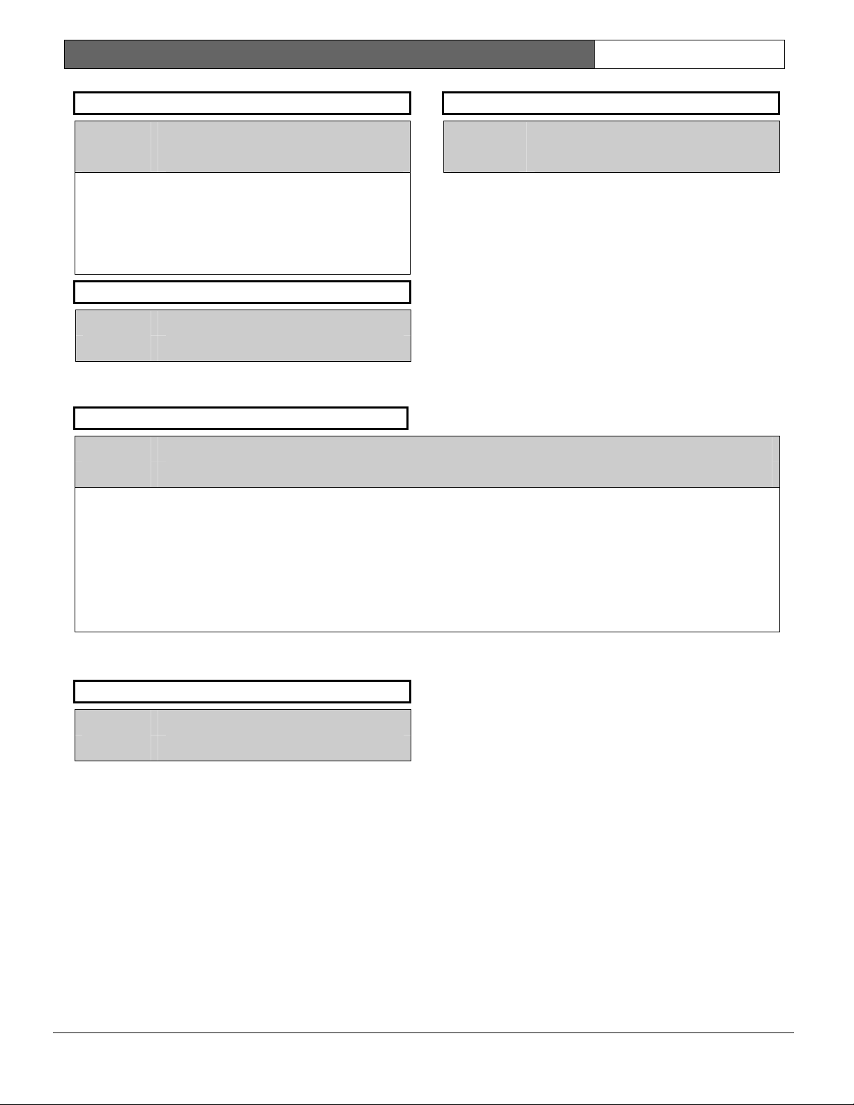
D9112B | Program Entry Guide | 2.0 Area Wide Parameters EN | 26
A# Delay Res
Default: No
Selection: Yes or No
Yes
No
A# Exit Tone
Default: Yes
Selection: Yes or No
Sound an exit tone during exit delay at command
centers assigned to this area.
A# Auto Watch
Default: No
Selection: Yes or No
Yes When disarmed, this area automatically goes into watch mode regardless of the status of Watch
Restoral
area bell time expires, and the point
returns to normal.
Restoral
restores, regardless of bell time.
Mode before the area is armed.
report is delayed until the
reports are sent when point
A# Exit Dly Time
Default: 60
Selection: 0 to 600
Exit delay time for this area. Select an entry that is a
five sec. increment.
Points programmed for “instant” alarms generate
alarms immediately. Even during exit delay.
Note:
Fail to Close reports require exit delay time: If Fail
To Close in Opening and Closing is programmed
YES, you must enter an exit delay time.
Automatic Watch does not affect manual Watch Mode toggle. You can still control Watch Mode
using Command 6.
No Watch Mode status is maintained between arm/disarm cycles. If the Watch Mode was ON at the
time the area was armed, it will be ON again when the area is disarmed. If the Watch Mode was
OFF at the time the area is disarmed, it will be OFF when the area is disarmed.
Note:
Watch Mode does not work while the area is perimeter armed.
A# Verify Time
Default: 60
Selection: 10 to 60 sec.
Alarm Verification is designed for use with smoke
detectors to reduce the number of false fire alarms.
When
Verify Time
double check smoke detector point activations
before generating alarm signals.
Note:
Check with your Authority Having Jurisdiction (AHJ)
to determine the maximum verification time allowed.
Points are programmed individually to activate the
verification feature. See Point Index. Any resettable
fire point can activate alarm verification for the area
to which it is assigned. Bosch Security Systems
recommends the use of separate area alarmverification relays.
is programmed, the panel can
To enable alarm verification on a point, program
Point Index
Resettable
When an alarm verification point trips, the D9112
automatically removes power to all resettable points
connected to the areas
sensor reset removes power to the sensors for the
amount of time programmed in
power is reapplied, a 60 sec. confirmation window
begins. If the detector is still in alarm, or trips again
during the confirmation window, or if a different
resettable verification point in the area trips, an
alarm is generated.
Example 1:
Verify Time
verification cycle starts when the detector trips. No
report is generated.
Fire Point, Alarm Verify
as Yes.
Reset Sensors
, and
relay. The
Verify Time
is set for 20 seconds. The alarm
. When
Bosch Security Systems | 2/04 | 74-06145-000-D
Page 27
D9112B | Program Entry Guide | 2.0 Area Wide Parameters EN | 27
Immediately after the detector trips, the area’s sensor
reset relay interrupts power to points connected to it
for the time in
When power is restored to the points, the 60 sec.
confirmation window is established. If any detector
reset during the verification time is tripped again
during the confirmation window, an alarm is
generated. If no activity occurs during this period,
no alarm is generated and the verification window
ends. If a verification point trips again after the
window ends, a new verification cycle begins.
Table 16: Verify Time Examples
Verify Time
.
Example 2:
Verify Time
verification cycle starts when the detector trips. The
following events happen as described in example 1,
except the sensor reset is 50 seconds.
is set for 50 seconds. The alarm
Verification Point
Example 1: Total Cycle
time 80 seconds
Example 2: Total Cycle
time 110 seconds
2.2 Bell Parameters
Area #
Default: 1
Selection: 1 to 8
Enter the area number you are programming.
A# Fire Time
Default: 6
Selection: 1 to 90
Enter the number of minutes the bell rings for fire
alarm points.
The bell output begins as soon as the fire alarm
occurs. When the panel’s internal clock begins a new
minute, it considers the first minute expired. It shuts
off the bell when the programmed number of
minutes expire.
If a passcode is entered to silence the bell before the
time expires, and
YES in Phone, a
to the same phone that the alarm message is routed
to.
Note:
Check with your AHJ to determine the appropriate
time in your application.
Cancel
Cancel
Verify Time/Reset
Trip
☛
☛
report is programmed
report is generated and sent
Sensors
Power Removed
Ignore Activity
■ 20 Seconds ■
■ 50 Seconds ■
The output for the fire bell is determined by
programming in the Relays section of the program.
Relay A is the programmed default providing fire
bell output for all eight areas. Relay A is the D9112’s
on-board relay providing powered alarm output
from terminal 6. An optional D136 Relay can be
installed on the D9112 to provide powered alarm
output from terminal 7 (known as relay “B”).
Because the relay number is programmable by area,
you may change the relay number to provide
separate fire alarm outputs for each area. The relay
assigned provides bell output for the number of
minutes specified in
parttern set in
Summary Fire
A
section of the program. It does not follow bell
pattern or time.
Confirmation
Generate alarm if
additional activity
received.
■■■■■■
■■■■■■
Fire Time
Fire Pat
.
relay is also available in the Relays
Restart Alarm
Verification Cycle
if an Alarm
Verification Point
trips.
and follows the
Bosch Security Systems | 2/04 | 74-06145-000-D
Page 28

D9112B | Program Entry Guide | 2.0 Area Wide Parameters EN | 28
A# Fire Pat
Select the bell pattern this area uses to signal an alarm on a fire point.
Press the [SPACE] bar to scroll through the selections. Press [ENT] when the correct selection appears in the
display.
Default: Pulse
Selection: Steady, Pulse, CaStnd, TmCod3
Steady Steady output
Pulse Pulse March Time: 120 beats per minute at an even tempo
CaStnd California Standard: 10 sec. audible + 5 sec. silent + 10 sec. audible + 5 sec. silent.
Note:
This sequence repeats until bell time expires.
TmCod3 Temporal Code 3: 0.5 to 1.0 sec. audible + 0.5 sec. silent + 0.5 sec. to 1.0 sec. audible + 0.5 sec. silent
+ 0.5 sec. to 1.0 sec. audible + 2.5 sec. silent.
Note:
±
This sequence repeats for a minimum of three min. with
25% timing tolerance (1991 NFPA standards
allow automatic silencing as permitted by the AHJ, and carry a minimum ring time of five min.).
A# Burg Time
Default: 6
Because the relay number is programmable by area,
you may change the relay number to provide
separate alarm outputs for each area. The relay
assigned provides bell output for the number of
Selection: 1 to 90
Enter the number of minutes the bell rings for nonfire alarm points.
The bell output begins as soon as the alarm occurs.
When the panel’s internal clock begins a new
minute, it considers the first minute expired. It ends
the timing and shuts off the bell when the
programmed number of minutes expires.
If a passcode is entered to silence the bell before the
time expires, and
YES in Phone, a
Cancel
Cancel
report is programmed
report is generated and sent
to the same phone that the alarm message is routed
to.
The output for the alarm bell is determined by
programming in the Relays section of the program.
Relay A is the programmed default providing non-
minutes specified in
pattern set in
Summary Alarm
A
Burg Time
Burg Pat
.
and follows the
relay is also available in the
Relays section of the program. It does not follow bell
pattern or time.
A# Burg Pat
Default: Steady
Selection: Steady, Pulse, CaStnd, TmCod3
Select the bell pattern this area uses to signal an
alarm on a non-fire point.
See
Fire Pat
for a description of each selection.
Press the [SPACE] bar to scroll through the
selections. Press [ENT] when the correct selection
appears in the display.
fire alarm bell output for all eight areas. Relay A is
the D9112’s on-board relay providing powered
alarm output from terminal 6. An optional D136
Relay can be installed on the D9112 to provide
powered alarm output from terminal 7 (known as
relay “B”).
Bosch Security Systems | 2/04 | 74-06145-000-D
Page 29
D9112B | Program Entry Guide | 2.0 Area Wide Parameters EN | 29
A# Single Ring
This program item determines if an alarm from a
non-fire point can restart the alarm bell time with
each alarm event, or only initiate alarm output once
per arming period.
This does not silence the command center alarm bell
tone, nor prevent any reports. This feature does not
affect fire points. Fire points restart bell time with
each new alarm.
Default: No
Selection: Yes or No
Yes
No
A# Bell Test
Default: No
Selection: Yes or No
Provide alarm output from the programmed
Bell Relay
In areas that report opening and closing activity, the
bell test happens after the panel sends the
report and receives the acknowledgement from the
receiver. For proper operation of the bell, test in an
area where closings are reported:
• Program a phone number and appropriate
routing for the
• Program
• Do not suppress
in O/C Windows.
• Make sure all users have the authority to
generate
• Do not restrict
• If you are using opening and closing windows,
be sure that
programmed NO in Open/Close Options.
In areas that do NOT report opening and closing
activity, the alarm bell relay output for this area is
activated for two sec. after exit time expires. For
proper operation of the bell test, program
NO.
One bell output per arming. After one
alarm during the armed period, alarms
on non-fire points in the same area
cannot restart the bell.
Restart bell output with each alarm
event.
Alarm
for two sec. after arming the area.
Closing
Open/Close
Area O/C
YES.
Opening
Closing
reports.
Opening
Disable O/C in Window
report group.
and
Closing
and
Closing
reports
reports.
is
Area O/C
0101
0101
0101
Bell test may be erratic. If several areas
programmed for bell test are armed at the
same time, and all the areas share the same
alarm bell relay, the relay operation may be
erratic, or longer than expected.
For example, if all eight areas are
programmed for bell test, share the same
alarm bell relay, have the same exit delay
time, and are armed at the same time, the
bell may ring for as long as 16 sec. during
the bell test.
2.3 Opening and Closing
Use this programming category to define opening
and closing supervision characteristics for each area
in the D9112. In this category are two programming
modules: Open/Close Options and O/C Windows.
Additional programming in Authority Lvi Assign and
Phone Routing modules can affect
Closing
recommends that you review all four of these
modules before programming the D9112.
All arming and disarming activities create local
events which are stored in the panel’s event log and
printed on the local printer, if installed.
Programming determines if the reports are sent to
the central station.
About the default programming: To enable
typical area
supervision in Modem II, the only programming
change needed is to select a phone destination for
the reports in Phone Routing,
2.3.1 Open and Close Options
There are two different ways to generate
and
generate
account status and/or according to area status.
Account Opening and Closing Reports
Whether
are generated or not depends on programming in
A# Acct O/C
Area Opening and Closing Reports
Whether
generated or not depends on programming in
Area O/C
reports. Bosch Security Systems
Closing
Opening
Opening
reports from a D9112. You can
and
and
Closing
Account Opening
in this section of the program.
Area Opening
in this section of the program.
and
Opening
Closing
report
Open/Close
Opening
reports according to
and
Closing
Closing
reports are
and
.
reports
A#
Bosch Security Systems | 2/04 | 74-06145-000-D
Page 30

D9112B | Program Entry Guide | 2.0 Area Wide Parameters EN | 30
Selective Combinations of Account and Area
Opening and Closing Reports
You can eliminate
reports from selected areas in the account by
programming
an area that is not programmed for
and
Closing
close, only the
report is sent.
You can suppress
reports from selected users by programming
Area O/C
NO for their authority level. If a user, not
programmed for
reports, opens the first area in the account, or closes
the last area in the account, only the
Opening
Combining Account and Area Opening and
Closing Reports
To send both Account openings and closings, and
individual Area openings and closings for all areas in
the account, program
areas in the account, program
for all areas in the account, and program
O/C
YES, then programming
and
YES for the authority levels used in the areas.
Area Opening
A# Area O/C
reports is the first to open, or the last to
Account Opening
Area Opening
Area Opening
Closing
report is sent.
A# Acct O/C
and
Closing
NO for those areas. If
Area Opening
and
and
Closing
Closing
A#
L## Area O/C
and
Closing
Account
YES for all
A# Area O/C
YES
L## Area
Closing Reports: In this configuration, when areas
in the account are independently armed, each area
generates an
when the last area is armed, it also generates an
Account Closing
Opening Reports: In this configuration, when the
first area in the account is disarmed, it generates an
Account Opening
Opening
the account are disarmed, each area will generate an
Area Opening
Additional Opening/Closing Supervision Features
This section of the program also provides several
other features you can use to supervise opening and
closing activity by area.
and
Fail to Close
Acct O/C
you must program O/C Windows.
Area
Default: 1
Selection: 1 to 8
Enter the area number you are programming.
Area Closing
report.
report along with an
report. Then when the rest of the areas in
report.
report. In addition,
Area
Auto Close, Fail to Open
all work independently of the
feature. To use these features however,
A#
,
A# Acct O/C
This program item determines if
item the same for all areas in the account.
Default: No
Selection: Yes or No
Send
Yes
Opening
Use this selection if the panel reports to an automation system that cannot interpret multiple area
Opening/Closing
Format is in use and
Account Opening
An
After the
another
in an account is closed (armed).
information.
Note:
Account Opening
Account Opening
Opening and Closing Windows affect Account Opening and Closing reports: If an account opening or
closing is generated while an opening or closing window for this area is in effect, and
Window
sharing the same account number use the same Opening and Closing Window times.
No
Do not send
Account Opening
and
Closing
reports, or if
Opening
report is generated when the first area in an account is opened (disarmed).
is programmed YES, the report is not sent. Bosch Security Systems recommends that all areas
Opening
and
and
Closing
reports by account.
Modem Format
and
Closing
report is sent, disarming other areas in the account does not generate
report. An
reports are enabled).
Account Closing
Account Opening
reports are generated by this area. Program this
is programmed NO in the Phone category (BFSK
report is generated only when the last area
and
Closing
reports do not contain any area
Disable O/C in
Closing
reports by account.
Bosch Security Systems | 2/04 | 74-06145-000-D
Page 31

D9112B | Program Entry Guide | 2.0 Area Wide Parameters EN | 31
A# Area O/C
An
Area Opening
Closing
area information.
Default: Yes
Selection: Yes or No
report is sent to the central station when each individual areas is closed (armed). This report includes the
report is sent to the central station when each individual area is opened (disarmed). An
Area
Yes
No
Generate
reports to an automation system that cannot interpret multiple Area
Whether
Authority Level Assignment: The first factor is the authority level of the passcode entered. If a
passcode is required to arm or disarm, and the Authority Lvl Assign program item
disabled for the user’s authority level, the report is not sent. See the User Interface Authority Lvl Assign
section,
Note:
Opening/Closing Window: The second factor is whether or not an opening or closing “window” is
in effect at the time of the opening or closing. When a window is in effect, programming in
O/C in Window
Do not generate
Use this selection if the panel reports to an automation system that cannot interpret multiple
Opening/Closing
Format is in use and
Note:
Area Opening
Area Opening
L## Area O/C prompt
If a passcode is not required for arming or disarming and this item is YES, the area sends Opening and
Closing reports. Since there is no need to enter a passcode, there is no authority level screening to prevent the
report from being sent.
and
and
Closing
Closing
.
reports for this area. Do NOT use this selection if the panel
Opening/Closing
reports are sent or not depends on two factors:
reports.
L## Area O/C
is
Disable
determines whether or not the report is sent.
Area Opening
reports, or if
Opening
Even if
and closings are not reported by area when this item is NO.
Programming this item NO does NOT prevent Account Opening and Closing reports if they are enabled
in
L## Area O/C
A#Acct O/C
.
and
Closing
Modem Format
and
Closing
is Enabled for the authority level of the passcode used to arm or disarm, openings
reports for this area.
is programmed to NO in the Phone category (BFSK
reports are enabled).
Area
Bosch Security Systems | 2/04 | 74-06145-000-D
Page 32

D9112B | Program Entry Guide | 2.0 Area Wide Parameters EN | 32
A# Restricted O/C
This item determines if this area can restrict
Restricted Opening
A
disarmed after a non-fire alarm.
A
Restricted Closing
master armed with controlled points that were faulted during the arming sequence. The sequence of reports
generated by a restricted closing are:
Default: No
Selection: Yes or No
Yes
Restrict
generate
Note:
Opening /Closing Window does not affect this report: Windows do not prevent
Opening
Opening
reports.
No
Do not restrict
Regardless of programming in Authority Levels
area when this item is programmed NO.
report refers to the panel sending an
report refers to the panel sending an
Opening
and
Closing
Restricted Opening
If a passcode is not required for arming or disarming and this item is YES, the area only sends Restricted
Opening and Closing reports. In this case, restricted reports are sent without User ID.
and
Closing
/Closing reports when they are sent according to the rules for restricted Opening/Closing
reports from being sent. Early or late designations are NOT added to
Opening
Opening
and
Closing
Area Closing
report activity.
Area Opening
report ONLY when the area has been
report ONLY when the area is
Was Forced Armed, Forced Point, Forced Close
reports for this area.
and
Closing
and
Closing
reports.
reports for this area.
A# Area O/C
L## Restricted O/C
must be programmed YES to
, reports are not restricted in this
, then
Closing Report
Restricted
.
Bosch Security Systems | 2/04 | 74-06145-000-D
Page 33

D9112B | Program Entry Guide | 2.0 Area Wide Parameters EN | 33
A# Perimeter O/C
This item determines if this area can send
Modem Format
Perimeter Opening
A
being in a perimeter armed state. A
when the area is perimeter armed.
The area can be perimeter armed using either the perimeter instant, or perimeter delayed arming options. In these
cases, the area is only partially armed and is considered in a disarmed state for the following:
and
Closing
Default: No
Selection: Yes or No
Yes
No
reporting is required.
report refers to the panel sending an
reports and RAM II programming.
This area can send
Whether
the user’s authority level. If a passcode is required to arm or disarm, and the Authority Lvl Assign
program item L## Perimeter O/C is disabled for the Authority Level,
Closing
program, L## Perimeter O/C prompt.
Note:
Opening/Closing Window does not affect this report: Windows do not prevent
and
There are no reports for Perimeter Partial arming (Command 8).
This area can not send
Even if L## Perimeter O/C is Enabled for the authority level of the passcode used to perimeter arm or
disarm the area, reports are not sent when this item is programmed NO.
Perimeter Opening
reports are disabled for that user. See the User Interface, Authority Lvl Assign section of the
If a passcode is not required for perimeter arming or disarming and this item is YES, the area sends
Perimeter Opening and Closing reports. In this case, the report is sent without User ID.
Closing
Perimeter Opening
reports from being sent.
Perimeter Opening
Perimeter Closing
and
and
Closing
Perimeter Opening
and
Closing
Opening
report refers to the panel sending a
reports to the central station.
report when the area is disarmed after
Closing
report
Account Opening
Closing
reports for a particular user are sent or not depends on
reports.
Perimeter Opening
and
Perimeter Opening
and
Closing
reports.
A# Disable O/C in Window
This item determines if opening and closing activity is reported when it occurs inside an Opening or Closing
window as programmed in O/C Windows.
Reports are always logged and printed on a local printer, if installed.
Default: Yes
Selection: Yes or No
Yes
No
Do not send
window.
If an
Opening
See O/C Windows.
The active window must be a closing window for
for
Opening
Send
Opening
programmed window. If an opening or closing occurs outside of the appropriate window, it reports
but does NOT have an early or late modifier.
If you want to monitor all opening and closing activity, but you also want to use features provided
by Opening and Closing Windows, program this item to NO, and program appropriate O/C
Windows.
Opening
or
Closing
reports.
and
Closing
and
Closing
report occurs outside of a window, send it with an early or late modifier.
reports to the central station even when they occur inside a
reports to the central station if they occur inside an active
Closing
reports. It must be an opening window
Bosch Security Systems | 2/04 | 74-06145-000-D
Page 34

D9112B | Program Entry Guide | 2.0 Area Wide Parameters EN | 34
A# Auto Close
The panel can automatically arm the area at the end of the closing window.
Default: No
Selection: Yes or No
Yes The area automatically arms at the end of the close window.
When the area is armed automatically, the area sends a
Area O/C
but no
When the panel is armed automatically at the end of the closing window, all faulted points
(including non-bypassable points) are force armed, even if the number of faulted points exceeds the
limit set in
No Do not automatically arm the area at the end of the close window.
A# Fail To Open
is programmed YES. If
Area Closing
report is sent. See also
A# Force Arm Max
A# Area O/C
A# Acct O/C
.
Closing
is programmed NO, the area automatically arms,
report without a user ID if
.
A#
This entry allows you to determine if
Default: 0
Selection: 0 or 1
Yes
No
A# Fail To Close
This entry allows you to determine if
Default: 0
Selection: 0 or 1
Yes
No
Fail to Open
installed) at the end of the opening window if the area has not been disarmed. Normal
and
Closing
No
Fail to Open
Fail to Close
installed) at the end of the closing window if the area was not armed. An exit delay time must be
programmed in
programmed to use this feature.
If
Auto Close
YES, the
No
Fail to Close
reports are sent to the central station, logged, and recorded on a local printer (if
reports do not need to be programmed to use this feature.
reports or log events are generated.
reports are sent to the central station, logged, and recorded on a local printer (if
Exit Dly Time
is programmed YES, a
Fail to Close
reports or log events are generated.
Fail to Open
Fail to Close
reports are sent.
reports are sent.
. Normal
Opening
Fail to Close
report is followed by
and
Closing
report is sent. If
Closing Late
reports do not need to be
Disable O/C in Window
or
F(orce) Close Late
.
Opening
is
Bosch Security Systems | 2/04 | 74-06145-000-D
Page 35

D9112B | Program Entry Guide | 2.0 Area Wide Parameters EN | 35
2.4 O/C Windows
Set a schedule for disarming and arming. The
disarming and arming schedules provide several
independent features:
• Suppress normal
reports when
programmed YES.
• Generate a
disarmed on schedule when
is programmed YES.
• Provide a warning tone and PLEASE COME
NOW display at the command center when it is
time to arm the area.
• Generate a
armed on schedule when
programmed YES.
• Automatically arm the area at the end of the
closing window when
programmed YES.
Opening and closing schedules can be set up
independently. For example, if you only want to use
features provided by closing windows, leave times
blank in the opening window prompts and program
closing window times.
A worksheet is provided at the end of this section for
your convenience. Following the worksheet are
examples of how to program opening and closing
windows for particular applications.
About the Program Record Sheet: Two columns
labeled “Sked #” appear on the Program Record Sheet
provided with the D9112. These numbers appear in
D6500 reports and local printer reports when the
window
Window
Begin Time
Opening
and/or
Closing
A# Disable O/C in Window
Fail to Open
report if the area is not
A# Fail To Open
Fail to Close
report if the area is not
A# Fail To Close
A# Auto Close
executes.
is
is
is
Exceptions: To prevent the windows from
activating on certain days of the year, program
Holiday
Index. When
executes on the days of the week programmed
unless the date is designated as a Holiday by the
Holiday Index selected.
If opening and/or closing windows are only needed
on certain days of the year, do not program the
windows to execute on any days of the week.
Instead, program
Holiday Index with the days of the year you want
the window to be active.
Default: No
Selection: Yes or No
Yes
No
W## Monday
Default: No
Selection: Yes or No
Yes
No
W## Tuesday
Default: No
Selection: Yes or No
Yes
No
YES, and enable at least one Holiday
Xept Holiday
Xept Holiday
Activate this window on Sundays.
Do not activate this window on
Sundays.
Activate this window on Mondays.
Do not activate this window on
Mondays.
Activate this window on Tuesdays.
Do not activate this window on
Tuesdays.
is YES, the window
NO, and select a
Xept
Default: 1
Selection: 1 to 16
Enter the window number you want to program.
W## Sunday
This prompt, and the next six days of the week
prompts, select the days of the week that the
opening and/or closing windows are active.
Bosch Security Systems | 2/04 | 74-06145-000-D
W## Wednesday
Default: No
Selection: Yes or No
Yes
No
Activate this window on Wednesdays.
Do not activate this window on
Wednesdays.
Page 36

D9112B | Program Entry Guide | 2.0 Area Wide Parameters EN | 36
W## Thursday
Default: No
Selection: Yes or No
Yes
No
Activate this window on Thursdays.
Do not activate this window on
Thursdays.
W## Friday
Default: No
Selection: Yes or No
Yes
Activate this window on Fridays.
- Disarming the area between the
Window Start
and
Open Window Stop
time creates a local event in the D9112 log,
but does not send the
Opening
the central station.
- Disarming the area after the
Stop
and the next window’s
Begin
time (or midnight, whichever comes
first) generates an
adds a
• If
Disable O/C in Window
Late to Open
the area generates an
Opening
modifier.
is NO, disarming
Opening
the “early” or “late” modifier, regardless of when
the area is disarmed.
Open
report to
Open Window
Open Early
report and
report without
When you are programming multiple windows to
No
W## Saturday
Default: No
Selection: Yes or No
Yes
No
W## Open Early Begin
Default: _ _ : _ _
Selection:
This program item is one of three required to create
an opening window. To finish programming an
opening window,
Window Stop
Open Early Begin
Use
the panel to look for an opening window. When
Opening
disarming the area between midnight and the
Early Begin
addition:
• If Disable O/C in Window is YES:
- Disarming the area between the Open Early
Do not activate this window on
Fridays.
Activate this window on Saturdays.
Do not activate this window on
Saturdays.
HH:MM (hours and minutes)
00:00 to 23:59
Open Window Start
and
Open
must be programmed.
to set the time that you want
and
Closing
reports are enabled,
Open
time generates an
Opening
report. In
Begin time and the Open Window Start
time generates an
an
Early to Open
Opening
report and adds
modifier. (If the Open
Early Begin time is the same as the Open
Window Start time, the EARLY TO OPEN
modifier is not sent.)
activate on a single day, program the windows in
chronological order. Be careful not to program a
window’s
between any other window’s
and
0101
0101
0101
Open Early Begin
time for a time that is
Open Window Start
Open Window Stop
time.
Disabled windows have a blank “Begin”
time. If the entry for this prompt is blank, but
times are programmed for Open Window
Start and Open Window Stop the window
is disabled.
To disable the window, both the hours and minutes
spaces must be blank.
00:00 is Midnight, 23:59 is 11:59 p.m. Make entries
using a 24 hr. clock. For example, 7:00 a.m. is
entered as 07:00; 2:45 p.m. is entered as 14:45.
0101
0101
0101
Disable/Restart the panel to activate today’s
window. If you are programming a window
that needs to activate on the same day that
you are programming it, do a disable/restart
after programming.
W## Open Window Start
Default: _ _ : _ _
Selection:
HH:MM (hours and minutes)
Enter the time that you want the panel to start the
opening window. The window goes into effect at the
beginning of the minute.
See
Open Early Begin
for report feature
explanations.
0101
0101
0101
Do not use a time of 23:59 as a window
stop time unless another window begins on
the next day at 00:00.
Fail to Open reports are not sent for
windows that stop at 23:59.
Bosch Security Systems | 2/04 | 74-06145-000-D
Page 37

D9112B | Program Entry Guide | 2.0 Area Wide Parameters EN | 37
2.4.1 Programming Two Opening Windows on the Same Day
Table 17: Programming for Two Opening Windows on the Same Day
W# Day of Week Early
1
2
0101
0101
0101
S M T W T F S
S M T W T F S
Do not program a single window to cross the midnight boundary. This window stop time must be later
than the window start time. To program a window that effectively crosses the midnight boundary, you
have to program two windows.
OPEN CLOSE
Start Stop Early
Begin
06:00 07:00 08:00
13:00 14:00 15:00
Begin
For example, to program two windows for an area that opens between 11:30 p.m. and 12:30 a.m., five
days a week, use two windows as shown in Table 18:
2.4.2 Programming to Link Two Days Over Midnight
Table 18: Programming to Link Two Days Over Midnight
W# Day of Week Early
1
2
S M T W T F S
S M T W T F S
OPEN CLOSE
Start Stop Early
Begin
22:00 23:30 23:59
00:00 00:00 00:30
Begin
W## Close Early Begin
Default: _ _ : _ _
Selection:
HH:MM (hours and minutes)
00:00 to 23:59
This program item is one of three required to create
a closing window. To finish programming a closing
window,
Stop
Use
panel to look for a closing window. When
and
between midnight and the
generates a
Close Window Start
must be programmed.
Close Early Begin
Closing
reports are enabled, arming the area
Closing
to set the time you want the
report. In addition:
and
Close Window
Opening
Close Early Begin
time
• If Disable O/C in Window is YES:
- Arming the area between the
Begin
time and the
time generates a
Closing Early
Early Begin
time is the same as the
Window Start
Close Window Start
Closing
modifier. (If the
time, the CLOSING EARLY
Close Early
report and adds a
Close
Close
modifier is not sent.)
Start Stop eXcept On
Start Stop eXcept On
- Arming the area between the
Holiday
Holiday
Yes No
Yes No
Holiday
Yes No
Yes No
Index
1 2 3 4
1 2 3 4
Holiday
Index
1 2 3 4
1 2 3 4
Area(s)
1 2 3 4 5 6 7 8
1 2 3 4 5 6 7 8
Area(s)
1 2 3 4 5 6 7 8
1 2 3 4 5 6 7 8
Close
Window Start
Stop
time creates a local event in the D9112
log but does not send the
and the
Close Window
Closing
report to
the central station.
- Arming the area after the
Stop
and the next window’s
Begin
time (or midnight, whichever comes
sooner) generates a
adds a
• If
Disable O/C in Window
Closing Late
the area generates a
Closing
Close Window
Close Early
Closing
reports and
modifier.
is NO, disarming
report without the
“early” or “late” modifier, regardless of when the
area is armed.
When you are programming multiple windows to
activate on a single day, program the windows in
chronological order. Be careful not to program a
window’s
between any other window’s
and
Close Early Begin
Close Window Stop
time for a time that is
Close Window Start
time.
Bosch Security Systems | 2/04 | 74-06145-000-D
Page 38

D9112B | Program Entry Guide | 2.0 Area Wide Parameters EN | 38
0101
0101
0101
Disabled windows have a blank “begin”
time. If the entry for this prompt is blank, but
the times are programmed for Close
Window Start and Close Window Stop the
window is disabled.
To disable the window, both the hours and minute
spaces must be blank.
00:00 is Midnight and 23:59 is 11:59 p.m. Make
entries using a 24 hr. clock. For example, 7:00 a.m.
is entered as 07:00, and 2:45 p.m. is entered as
14:45.
0101
0101
0101
Disable/Restart the panel to activate today’s
window. If you are programming a window
that needs to activate on the same day that
you are programming it, do a disable/restart
after programming.
W## Close Window Start
Default: _ _ : _ _
Selection:
HH:MM (hours and minutes)
Enter the time that you want the panel to start the
closing window. The window goes into effect at the
beginning of the minute.
A warning tone sounds and PLEASE CLOSE NOW
displays at the command center if the area is not
armed when the
Close Window Start
time comes.
To temporarily silence the tone, press the [ESC] key
on the command center. The warning tone restarts
in ten min. if the area is not armed.
See
Close Early Begin
for report feature
explanations.
W## Close Window Stop
Default: _ _ : _ _
Selection:
HH:MM (hours and minutes)
Enter the time that you want the panel to start the
closing window. The window stops at the end of a
minute.
If the area is not armed by the time the
Window Stop
Fail to Close
Close Early Begin
See
time expires, the panel generates a
report if enabled in
for other report feature
Close
Fail To Close
.
explanations.
0101
0101
0101
Do not use a time of 23:59 as a window
stop time unless the window continues on
the next day at 00:00. Fail to Close reports
are not sent, and the Auto Close feature
does not work for windows that stop at
23:59.
Do not program a single window to cross
the midnight boundary. The window stop
time must be later than the window start
time. To program a window that effectively
crosses the midnight boundary, you have to
program two windows.
For example, to program windows for an
area that closes between 11:30 p.m. and
12:30 a.m., five days a week, use two
windows as shown in Table 19
Table 19: W# Close Window Stop Programming Example
W# Day of Week Early
1
2
S M T W T F S
S M T W T F S
OPEN CLOSE
Start Stop Early
Begin
22:00 23:30 23:59
00:00 00:00 00:30
Bosch Security Systems | 2/04 | 74-06145-000-D
Begin
Start Stop eXcept On
Holiday
Yes No
Yes No
Holiday
Index
1 2 3 4
1 2 3 4
Area(s)
1 2 3 4 5 6 7 8
1 2 3 4 5 6 7 8
Page 39

D9112B | Program Entry Guide | 2.0 Area Wide Parameters EN | 39
W## Xept Holiday
You can determine if the window is disabled on
holidays, or is active only on holidays.
To prevent the windows from activating on certain
days of the year, program
enable at least one Holiday Index. When
Holiday
is programmed YES, the window executes
Xept Holiday
YES, and
Xept
on the days of the week programmed unless the
date is designated as a Holiday by the Holiday
Index(es) selected.
Default: No
Selection: Yes or No
Yes
Do not activate this window on
holidays.
To use this selection, the window
must be programmed to activate on at
least one day of the week and a
Holiday Index must be enabled.
No
A holiday will not prevent this
window from activating.
You also use this selection if opening
and/or closing windows are only
needed on certain days of the year.
Do not program the windows to
execute on any days of the week.
Instead, program
Xept Holiday
NO,
and select at least one Holiday Index
with the days of the year you want the
window to be active.
2.4.3 Holiday Indexes for O/C Windows
You can enable up to four Holiday Indexes for use
with Opening/Closing Windows. Enable at least one
Holiday Index if
W## Xept Holiday
is
programmed YES for this window, or if you want
this window to activate only on specific dates.
Holidays are programmed in the Holiday Indexes
section of the program.
W## Holiday 1
W## Holiday 2
Default: No
Selection: Yes or No
Yes
Use Holiday Index 2 with this
window.
No
Do not use Holiday Index 2 with this
window.
W## Holiday 3
Default: No
Selection: Yes or No
Yes
Use Holiday Index 3 with this
window.
No
Do not use Holiday Index 3 with this
window.
W## Holiday 4
Default: No
Selection: Yes or No
Yes
Use Holiday Index 4 with this
window.
No
Do not use Holiday Index 4 with this
window.
W## Area #
Eight separate program items determine whether a
particular window activates in each of the eight areas
of the panel.
Default: No
Selection: Yes or No
Yes
Activate the window in the area
number (#) specified.
No
Disable the window in the area
number (#) specified.
Default: No
Selection: Yes or No
Yes
Use Holiday Index 1 with this
window.
No
Do not use Holiday Index 1 with this
window.
Bosch Security Systems | 2/04 | 74-06145-000-D
Page 40

D9112B | Program Entry Guide | 2.0 Area Wide Parameters EN | 40
2.4.4 Opening/Closing Windows Worksheet
Use Table 21 to determine the proper entries for your application.
Table 20: Opening/Closing Windows Worksheet
W# Day of Week
1 S M T W T F S
2 S M T W T F S
3 S M T W T F S
4 S M T W T F S
5 S M T W T F S
6 S M T W T F S
7 S M T W T F S
8 S M T W T F S
9 S M T W T F S
10 S M T W T F S
11 S M T W T F S
12 S M T W T F S
13 S M T W T F S
14 S M T W T F S
15 S M T W T F S
16 S M T W T F S
OPEN CLOSE
Early
Begin Start Stop
_ _:_ _ _ _:_ _ _ _:_ _ _ _:_ _ _ _:_ _ _ _:_ _
_ _:_ _ _ _:_ _ _ _:_ _ _ _:_ _ _ _:_ _ _ _:_ _ Yes No 1 2 3 4
_ _:_ _ _ _:_ _ _ _:_ _ _ _:_ _ _ _:_ _ _ _:_ _
_ _:_ _ _ _:_ _ _ _:_ _ _ _:_ _ _ _:_ _ _ _:_ _ Yes No 1 2 3 4
_ _:_ _ _ _:_ _ _ _:_ _ _ _:_ _ _ _:_ _ _ _:_ _
_ _:_ _ _ _:_ _ _ _:_ _ _ _:_ _ _ _:_ _ _ _:_ _ Yes No 1 2 3 4
_ _:_ _ _ _:_ _ _ _:_ _ _ _:_ _ _ _:_ _ _ _:_ _
_ _:_ _ _ _:_ _ _ _:_ _ _ _:_ _ _ _:_ _ _ _:_ _ Yes No 1 2 3 4
_ _:_ _ _ _:_ _ _ _:_ _ _ _:_ _ _ _:_ _ _ _:_ _
_ _:_ _ _ _:_ _ _ _:_ _ _ _:_ _ _ _:_ _ _ _:_ _ Yes No 1 2 3 4
_ _:_ _ _ _:_ _ _ _:_ _ _ _:_ _ _ _:_ _ _ _:_ _
_ _:_ _ _ _:_ _ _ _:_ _ _ _:_ _ _ _:_ _ _ _:_ _ Yes No 1 2 3 4
_ _:_ _ _ _:_ _ _ _:_ _ _ _:_ _ _ _:_ _ _ _:_ _
_ _:_ _ _ _:_ _ _ _:_ _ _ _:_ _ _ _:_ _ _ _:_ _ Yes No 1 2 3 4
_ _:_ _ _ _:_ _ _ _:_ _ _ _:_ _ _ _:_ _ _ _:_ _
_ _:_ _ _ _:_ _ _ _:_ _ _ _:_ _ _ _:_ _ _ _:_ _ Yes No 1 2 3 4
Table 21: Opening/Closing Windows
Early
Begin Start Stop
eXcept
On
Holiday
Yes No
Yes No
Yes No
Yes No
Yes No
Yes No
Yes No
Yes No
Holiday
Index Area(s)
1 2 3 4
1 2 3 4
1 2 3 4
1 2 3 4
1 2 3 4
1 2 3 4
1 2 3 4
1 2 3 4
1 2 3 4 5 6 7 8
1 2 3 4 5 6 7 8
1 2 3 4 5 6 7 8
1 2 3 4 5 6 7 8
1 2 3 4 5 6 7 8
1 2 3 4 5 6 7 8
1 2 3 4 5 6 7 8
1 2 3 4 5 6 7 8
1 2 3 4 5 6 7 8
1 2 3 4 5 6 7 8
1 2 3 4 5 6 7 8
1 2 3 4 5 6 7 8
1 2 3 4 5 6 7 8
1 2 3 4 5 6 7 8
1 2 3 4 5 6 7 8
1 2 3 4 5 6 7 8
Day of Week
Program at least one
day as Yes.
Program at least one
day as Yes.
Program at least one
day as Yes.
All days must be
programmed No.
* This column describes how to activate an Opening/Closing Window. Use the guidelines shown in the other columns to
choose the appropriate entries.
Activating an
Opening/Closing
Window * eXcept On Holiday Holiday Index Areas
Day(s) of the Week
Day(s) of the Week,
but NOT on Holidays
Day(s) of the Week,
PLUS Holidays
Only on Holidays
No
Yes
No
No
None Program at least one
area as Yes.
Select at least one
Index
Select at least one
Index
Select at least one
Index
Program at least one
area as Yes.
Program at least one
area as Yes.
Program at least one
area as Yes.
Bosch Security Systems | 2/04 | 74-06145-000-D
Page 41

D9112B | Program Entry Guide | 2.0 Area Wide Parameters EN | 41
Table 22: Normal Store Hours*
W# Day of Week
1
S M T W T F S
2
S M T W T F S
* Monday through Friday, Opening between 5 and 6 a.m. Closing between 11:00 p.m. and 1:00 a.m.
OPEN CLOSE
Early
Begin Start Stop
04:00 05:00 06:00 20:00 23:00 23:59
_ _:_ _ _ _:_ _ _ _:_ _ 00:00 00:00 01:00
Early
Begin Start Stop
eXcept
On
Holiday
Yes No
Yes No
Holiday
Index Area(s)
1 2 3 4
1 2 3 4
Table 23: Delivery Schedule*
W# Day of Week
3
S M T W T F S
Program at
OPEN CLOSE
Early
Begin Start Stop
02:30 02:45 03:00 03:05 03:15 03:30
Day(s) of the week, but NOT on holidays. Yes Select
Early
Begin Start Stop
least one day
as Yes.
* Monday and Wednesday, In between 2:45 and 3:00 a.m. Out between 3:15 and 3:30 a.m.
eXcept
On
Holiday
Yes No 1 2 3 4 1 2 3 4 5 6 7 8
Holiday
Index Area(s)
at least
one
index.
Another alternative for delivery schedules is to automatically bypass specific points using Skeds.
1 2 3 4 5 6 7 8
1 2 3 4 5 6 7 8
Program at
least one area
as Yes.
Table 24: Monthly Auditor’s Schedule*
W# Day of Week
4 S M T W T F S
All days must
OPEN CLOSE
Early
Begin Start Stop
07:00 08:00 08:30 14:00 14:30 17:00
Only on holidays. No Select
Early
Begin Start Stop
be
programmed
No.
* Sunday, In between 8:00 and 8:30 a.m. Out between 2:30 and 5:00 p.m.
eXcept
On
Holiday
Yes No 1 2 3 4 1 2 3 4 5 6 7 8
Holiday
Index Area(s)
Program at
at least
one
index.
least one area
as Yes.
Bosch Security Systems | 2/04 | 74-06145-000-D
Page 42

D9112B | Program Entry Guide | 2.0 Area Wide Parameters EN | 42
2.5 Command Center
This programming module contains three
programming categories:
• Cmd Cntr Assignment
System Security Notice: Install unsupervised
command centers inside the protected area. All
equipment installed outside of the protected area
should be enclosed in tamper resistant housing.
CC# Scope
• Area Text
• Custom Function
2.5.1 Cmd Cntr Assignment
Determines if the command center is supervised and
which area information the command center
displays.
Cmd Center #
Default: 1
Selection: 1 to 8
Enter the command center address you want to
program. Corresponding DIP switches on the
command center are set to identify each command
center. See the D9112B Program Record Sheet for DIP
switch settings for each address.
Scope determines if the command center is capable
of viewing the status and arming and disarming
areas other than the one to which the command
center is assigned.
A Security System Owner’s Guide is
provided with each panel. This guide further
explains how Scope and other relationships
like Authority Levels and Skeds affect
command center displays and operation.
Press the [SPACE] bar to scroll through the
selections. Press [ENT] when the correct selection
appears in the display.
Default: PanelWide (address 1 only)
Selection: PanelWide, Account. Area, or No
Keypad 0 or 1
CC# Supervised
This entry tells the panel if the command center at
the address specified is supervised. The panel polls
the command centers by address number. If a
supervised address does not respond, an
SDI Fail
report with the address number is sent to the log.
SERVC KEYPAD displays at all other command
centers, and a report is sent to the
Diagnostic
phone
route, if programmed.
Default: No
Selection: Yes or No
Yes
Only one command center can be installed
with this address number (see the command
center manual for address switch settings).
If the address number is supervised and the
DIP switches for more than one command
center are programmed for this address, the
command centers intermittently sound the
keypad encoding tone.
No
More than one command center can be
installed with this address number.
Command centers with the same address
echo the operation of all other command
centers with the same address (in other
words, they all show the same displays and
emit the same tones at the same time).
PanelWide A Panel-Wide Command Center can
view information and perform arming
and disarming functions for all areas
in the panel. A Panel-Wide command
center can cross account boundaries.
Account An Account Command Center can
view information, and perform arming
and disarming functions for all areas
that are assigned to the same account
as the area where the command
center is assigned. An Account
command center cannot cross
boundaries.
Area An Area Command Center can view
information and perform arming and
disarming functions only for the area
to which it is assigned.
No Keypad No command center installed at this
address. CALL FOR SERVICE
displays at command centers
programmed for this address.
Bosch Security Systems | 2/04 | 74-06145-000-D
Page 43

D9112B | Program Entry Guide | 2.0 Area Wide Parameters EN | 43
CC# Area
Default: 1
Selection: 1 to 8
Each installed command center must be assigned to
an area of the D9112. This allows proper event
displays as well as user authority operations.
Blank entries are not acceptable.
2.5.2 Area Text
Create custom “Idle Text” displays for the command
centers.
Area
Default: 1
Selection: 1 to 8
Each area number you are programming.
Area # Is On
Default: See
Selection:
Note:
Period (.), comma (,), percent (%), parenthesis [()],
equal (=), greater/less than (< >), exclamation (!),
and colon (:) are not allowed.
Text that displays at command centers assigned to
this area when the area is master armed. The text for
each area is programmed separately, so each area
can have a custom display.
Check the Program Record Sheet (P/N: 74-06447-000)
for default text.
Area # Not Ready
Default: See
Selection:
Note:
Period (.), comma (,), percent (%), parenthesis [()],
equal (=), greater/less than (< >), exclamation (!),
and colon (:) are not allowed.
Text that displays at command centers assigned to
this area when the area is disarmed and has faulted
points. Enter the text that displays at command
centers when the area has faulted controlled points.
Program Record Sheet
16 alphanumeric characters - enter
alphabetic characters A to Z in capital
letters.
Program Record Sheet
16 alphanumeric characters - enter
alphabetic characters A to Z in capital
letters.
The text for each area is programmed separately, so
each area can have a custom display.
Check the Program Record Training Sheet (P/N: 7406447-000) for default text.
Area # Is Off
Default: See
Selection:
Note:
Period (.), comma (,), percent (%), parenthesis [()],
equal (=), greater/less than (<>), exclamation (!),
and colon (:) are not allowed.
Text that displays at command centers assigned to
this area when the area is disarmed. Enter the text
that displays at command centers when the area is
ready to be armed (there are no faulted controlled
points).
The text for each area is programmed separately, so
each area can have a custom display.
Check the Program Record Sheet (P/N: 74-06447-000)
for default text.
Area # Acct Is On
Default: Blank
Selection:
Note:
Period (.), comma (,), percent (%), parenthesis [()],
equal (=), greater/less than (< >), exclamation (!),
and colon (:) are not allowed.
When all areas in the account are master armed, the
Area # Is On
The
Acct Is On
that are assigned to this area. (See Cmd Cntr
Assignment
Number
Each area can have unique
can program the same text in each area of the
account.
A blank entry disables the
this area. Each area’s armed text continues to display
after the last area in the account is armed.
CC# Area
.)
Program Record Sheet
16 alphanumeric characters - enter
alphabetic characters A to Z in capital
letters.
16 alphanumeric characters - enter
alphabetic characters A to Z in capital
letters.
text is replaced by
text appears at all command centers
, and Area Parameters
Acct Is On
Acct Is On
Acct Is On
text.
Account
text, or you
display for
Bosch Security Systems | 2/04 | 74-06145-000-D
Page 44

D9112B | Program Entry Guide | 2.0 Area Wide Parameters EN | 44
2.5.3 Custom Function
Custom Functions are a way to simplify the use of
complex keystroke sequences that can be entered at
the command center. These items are similar to
“speed dialing” on a telephone. In other words, they
can be programmed to perform a series of
keystrokes that automatically perform specific
functions with a single menu entry.
Each menu item has a 16 character programmable
title (see
CF# Text
). Use the text to describe the
function so that the user understands what happens
when using the menu item.
Once programmed the Custom Function item
number can be added to the Command Menu. The
user accesses the Command Menu using the
[MENU/ESC] key at the command center.
Access to menu items from specific command center
addresses is determined by programming Command
Menu in the User Interface section of the program.
The user must have the appropriate authority level
to use the functions executed by the Custom
Function. The Scope of the command center used to
access the Custom Function item must also be
considered. This is especially important when the
Custom Function is used to execute arming and
disarming functions. For a further discussion see
CF# Key Stroke
0101
0101
0101
Test all Custom Functions! Incorrect entries
in CF### Key Stroke can cause
unexpected operation. For example, with
certain combinations of entries, a portion of
.
the function can start repeating in an
endless loop and may disable the panel. If
this happens during testing, reboot the
panel using the reset pin and reprogram the
keystrokes for the function.
Custom Function ###
Default: 128
Selection:
128 to 143
Enter the Custom Function number you want to
program. You can program up to 16 Custom
Functions, which are numbered 128 to 143.
CF### Text
Default: See
Selection:
Program Record Sheet
16 alphanumeric characters - enter
alphabetic characters A to Z in capital
letters.
Note:
Period (.), comma (,), percent (%), parenthesis [()],
equal (=), greater/less than (< >), exclamation (!),
and colon (:) are not allowed.
Determines the menu text displayed at the
command center for the Custom Function item. Use
this text to represent the functions performed by this
menu item. You can program up to 16 characters for
each Custom Function.
CF### Key Strokes
Default: See Training Sheet
Selection:
Up to 32characters: 0 to 9, A, B, C, D,
and E
The keystrokes simulate any sequence of keystrokes
the user can perform at a command center. You can
program up to 32 keystrokes for each Custom
Function. Use Table 25 to enter appropriate
keystrokes.
Table 25: CF## Keystrokes
Selection Key Faceplate
Label
0 to 9 = 0 to 9
A = COMMAND
B = PREV (Previous) up arrow
C = ESC (Escape) MENU
D = NEXT down arrow
E = ENT (Enter) YES
0101
0101
0101
D5200 Data Entry:
Use the D5200 down-arrow key to move the
cursor to the first data entry line. When you
want to enter more than 16 keystrokes, the
first line of the data entry line must be filled
before you move on to the second line. If
you make entries on the second line, and
the first line has less than 16 characters, the
second line clears when you press [ENT].
Command Center Function/Authority Lvl
Assign affects how a Custom Function executes:
Depending on the programming in User Interface,
some functions may require a passcode before a
function executes. When a passcode is required,
either embed the passcode within the function, or
make the function requiring the passcode the LAST
one in the keystroke string.
Bosch Security Systems | 2/04 | 74-06145-000-D
Page 45

D9112B | Program Entry Guide | 3.0 User Interface EN | 45
Command Center Scope affects how a Custom
Function executes:
The
Scope
of the command center where the
Custom Function is accessed can affect the way the
Custom Function operates.
2.5.4 Programming Custom Function
Keystrokes
• Find the command you want to execute on the
User Interface page of the Program Record Sheet.
• Single digit commands must be programmed
with “9” as the second digit.
Table 26: CF## Custom Function Keystrokes
Command Keystroke
1 (Master Arm Area) A19
2 (Perimeter Instant Arm) A29
3 (Perimeter Delay Arm) A39
6 (Watch Mode) A69
7 (Special Alert) A79
8 (Perimeter Partial Area) A89
9 (Special Alert) A99
0 (Bypass a Point) A09
• Some functions cannot be entered directly using
a Command number because they are nested
inside a higher level function. To automatically
execute these functions, you must add the
appropriate keystrokes.
• For example, in the Change Display (CMD 49)
function there are three sub-functions:
- Bright Display: Enter [A] [4] [9] [E]
- Dim Display: Enter: [A] [4] [9] [D] [E]
- Date/Time Display: Enter [A] [4] [9] [B]
[E]
• Custom Functions can perform several tasks at
once. For example: To toggle relays 7, 8 and 9
in one Custom Function enter: [A] [5] [4] [7] [E]
[E] [8] [E] [E] [9] [E] [E] [C]
• To program multiple area arming or disarming
functions, use keystroke sequences including
[COMMAND][50] (Move to Area) and
[COMMAND][1].
The previous examples assume none of the
functions require a passcode.
3.0 User Interface
This programming module contains three
programming categories: Cmd Center Functions,
Authority Lvl Assign, and Command Menu. Use these
programming categories, and Custom Function in the
Command Center module, to enable user interface
features.
There are two ways to access command center
functions: Commands and the Command Menu.
The Security System User’s Guide provides instructions
on how to access the Command Menu along with
step by step instructions for basic command center
functions. The Security System Owner’s Manual
explains the more advanced features.
3.1 Commands
“Commands” is the same method of command
initiation used in previous Bosch Security Systems’
products. This method is made available to provide
continuity in the arming commands across product
line and to make an easy transition for dealers using
other Bosch Security Systems products. With
commands, the end user presses the [COMMAND]
key and then the numeral of the command they
want to initiate. For example pressing [Command]
[2]” arms the perimeter of the area.
The D9112 Program Record Sheet lists the commands
available with the D9112 system. Command
numbers are shown in the third column (labeled
“Command”) next to the function name. If a
particular function does not have a command
number, it can only be accessed through the
Command Menu.
If the end user is going to use only commands to
operate their system, along with arming and
disarming by entering a passcode, then you do not
need to program Custom Function or Command Menu.
3.2 Command Menu and Custom
Functions
The Command Menu is accessed when the user
presses the [ESC]/[MENU] key while the command
center is displaying idle text. Each command center
address can display a unique list of functions to suit
the application. The function name shown in the
second column on the Program Record Sheet appears
in all capital letters in the command center display
when the function is programmed for the Command
Menu. See Command Menu for instructions.
Bosch Security Systems | 2/04 | 74-06145-000-D
Page 46

D9112B | Program Entry Guide | 3.0 User Interface EN | 46
Custom functions simplify the use of the command
center by providing a method of displaying complex
functions in a simplified form using custom text.
Custom Functions can only be accessed through the
Command Menu.
In order to use command center functions in
See the Security System User’s Guide for
descriptions and operating instructions for
the most commonly used functions. See
the Security System Owner's Guide for
advance command center functions.
Custom Function programming, the functions must
be enabled as described in Cmd Center Functions.
If a function that requires the use of a passcode is
programmed for a Custom Function, the user’s
passcode must have the authority to execute the
function in at least one of the areas within the scope
of the command center, otherwise, NO
AUTHORITY displays.
0101
0101
0101
Fill out the Program Record Sheet as you
design the system.
To enable a function panel wide with no
restrictions, enter an “E” in the fourth
column. To completely disable it, enter a
blank in the fourth column. To restrict use to
users with a particular authority level, place
a “P” in the fourth column next to the
function.
You only need to program Authority Levels
for functions restricted by passcode. To
enable a function for a particular authority
level, put an “E” under the authority level
column. A blank under an authority level
disables the function for the authority level
specified.
In the User Interface section of this guide, descriptions
of prompts found in Cmd Center Functions and
Authority Lvl Assign are combined. This makes the
relationship between the two sections easier to
understand when you are learning how to program
the panel.
0101
0101
0101
In the D5200 programmer, the prompts for
Center Functions
Cmd Center Function prompts are shown
in plain boxes. Authority Lvl Assign prompts
are shown in dashed boxes.
Cmd
and Authority Lvl Assign appear in
3.3 Cmd Center Function
Programming choices in this section of the program
determine if command center functions are disabled
(Blank), enabled (E), or restricted (P) panel-wide.
Table 27: Command Center Function Selections
Blank Disable the function panel-wide.
E Enable the function panel-wide. The
P Passcode required. When the passcode
3.4 Authority Lvl Assign
Use this section to program command center
functions so that they can be used by specific User
Authority Levels.
Programming Time Saver: Only functions that are
programmed to require a passcode (P) in the Cmd
Center Functions section of the program need to be
programmed in Authority Lvl Assign.
Functions that are disabled (Blank) in Cmd Center
Functions are disabled panel-wife for all authority
levels. Functions that are enabled (E) in Cmd Center
Functions are enabled panel-wide for all authority
levels.
Fill out the worksheets in the Owner’s
Guide when you are done, or remove the
Appendix section of the Owner’s Guide.
Accessing the function using a command
or the Command Menu displays NO
AUTHORITY.
function can be executed without entering
a passcode.
is entered at the command center, the
panel checks the authority level. See
Authority Lvl Assign.
separate sections of the User Interface module.
Bosch Security Systems | 2/04 | 74-06145-000-D
Page 47

D9112B | Program Entry Guide | 3.0 User Interface EN | 47
Table 28: Authority Level Selections
Blank
E
Disarm
There are two disarming functions enabled by this prompt: Disarm All Areas and Disarm An Area. Blank and E
are not valid entries for this item.
Disarm All Areas: Disarms all areas according to the
entered (see Cmd Cntr Assignment).
Disarm An Area: Disarms a single area. When this function is accessed the command center displays the armed
status of areas within its
Disable this function for the authority level specified.
Enable this function for the authority level specified. When the passcode is entered at the command
center, the panel checks the authority level. The panel executes the function only in areas where the
passcode has the authority to use the function.
When a passcode is entered into a command center that has either Account or Panel-Wide scope, the
user can use any panel-wide feature (such as Send a Report or Display Rev) as long as the user has
authority for the feature in at least one area where the command center has scope. If the function is area
specific the authority must be set for the specific function such as, Watch Mode.
Scope
of the command center where the function is
Scope
.
How Command Center Scope affects area execution: An Area Command Center can execute this
function only in the area where the command center is assigned. An Account command center can
Default: P
Selection: P
P Passcode is always required for this function. When the passcode is entered at the command center,
Default: See
Selection: Blank or E
Blank
E
execute this function in all areas in the account where the user has authority. A Panel-Wide Command
Center can execute this function in all areas in the panel where the user has authority.
the panel checks the authority level.
The panel disarms areas where the passcode is authorized within the
center. The command center display shows the disarmed areas.
Programming in O/C Options
Closing
L## Disarm
Disable this function for Authority Level (L##) specified.
Enable this function for Authority Level specified. When the passcode is entered at the command
center, the panel checks the authority level. The panel executes the function only in areas where the
passcode is authorized.
Programming in O/C Options
Closing
Whether
Area O/C
reports can be generated for a particular area.
Training Sheet
reports can be generated for a particular area.
Opening
and
and
L## Restricted O/C
Area O/C
Area O/C
Closing
and
Restricted O/C
and
Restricted O/C
reports are generated by this user or not depends on the
prompts in Authority Lvl Assign.
determines whether
determines whether
Scope
of the command
Opening
Opening
L##
and
and
Bosch Security Systems | 2/04 | 74-06145-000-D
Page 48

D9112B | Program Entry Guide | 3.0 User Interface EN | 48
Master Arm
There are three arming functions enabled by this prompt:
• Master Arm All Areas: Arms all areas according to the
Scope
of the command center where the function is
entered (see Cmd Cntr Assignment).
• Master Arm an Area: Allows the user to select a single area to arm.
• Command 1: Local area arming; only arms the area where the command center is assigned.
How command center Scope affects area execution:
An Area Command Center can execute this function only in the area where the command center is
assigned. An Account Command Center can execute this function in all areas in the account where the
user has authority. A Panel-Wide Command Center can execute this function in all areas in the panel
where the user has authority.
Default: P
Selection: Blank, E, or P
Blank Disable the function panel-wide. Attempting to access the function displays NO AUTHORITY.
E Enable this function panel-wide. The function can be executed from any area within the command
center’s Scope without entering a passcode.
Programming in O/C Options Area O/C and Restricted O/C determines whether
Opening
and
Closing
reports can be generated for a particular area.
P Passcode required. When the passcode is entered at the command center, the panel checks the
authority level.
The panel only arms areas where the passcode is authorized that are within the Scope of the
command center. The command center display shows the areas it is arming.
0101
0101
0101
Force Arming: If a passcode is not required to arm these functions, all authority levels can force arm. To
disable force arming in an area, enter 0 in FA Bypass Max in the Area Parameters section of the program.
L## Master Arm
Default: See
Program Record Sheet
Selection: Blank or E
Blank Disable this function for Authority Level (L##) specified, if this item in Command Center Function
requires a passcode (P).
E Enable this function for Authority Level specified. When the passcode is entered at the command
center, the panel checks the authority level. The panel executes the function only in areas where the
passcode is authorized.
Programming in O/C Options
Closing
Whether
Area O/C
reports can be generated for a particular area.
Opening
and
and
L## Restricted O/C
Area O/C
Closing
and
Restricted O/C
determines whether
Opening
reports are generated by this user or not depends on the
prompts in Authority Lvl Assign.
Bosch Security Systems | 2/04 | 74-06145-000-D
and
L##
Page 49

D9112B | Program Entry Guide | 3.0 User Interface EN | 49
Mstr Arm Inst
Master Arm Instant: [COMMAND] [1] [1]
There are three instant master arming functions enabled by this prompt: Master Arm All Areas Instant, Master
Arm An Area Instant, and Command 11 Local Area Arm Instant.
Normally, these instant master arming functions provide no entry or exit delay, however, if a disable restart is
performed while the area is instant master armed, then an entry delay is provided for the current armed cycle.
Master Arm All Areas (Instant): Arms all areas according to the
Scope
of the command center where the
function is entered (see Cmd Cntr Assignment). No entry or exit delays are provided with this arming function.
Master Arm An Area (Instant): Allows the user to select a single area to arm. No entry or exit delays are
provided with this arming function.
Command 11: Only arms the area where the command center is assigned. No entry or exit delays are provided
with this arming function.
How command center Scope affects area execution:
An Area command center can execute this function only in the area where the command center is
assigned. An Account command center can execute this function in all areas in the account where the
user has authority. A Panel-Wide command center can execute this function in all areas in the panel
where the user has authority.
Default: Blank
Selection: Blank, E, or P
Blank Disable the function panel-wide. Accessing the function using a command, the Command Menu, or
a custom function, displays NO AUTHORITY.
E Enable this function panel-wide. The function can be executed from any area within the command
center’s Scope without entering a passcode.
Programming in O/C Options
Closing
reports can be generated for a particular area.
Area O/C
and
Restricted O/C
determines whether
Opening
and
P Passcode required. When the passcode is entered at the command center, the panel checks the
authority level.
The panel only arms areas where the passcode is authorized and within the
Scope
of the command
center. The command center display shows the areas it is arming.
0101
0101
0101
Force Arming: If a passcode is not required to arm these functions, all authority levels can force arm. To
disable force arming in an area, enter 0 in FA Bypass Max in the Area Parameters section of the program.
Bosch Security Systems | 2/04 | 74-06145-000-D
Page 50

D9112B | Program Entry Guide | 3.0 User Interface EN | 50
L## Master Arm Inst
Master Arm
Default: See
Program Record Sheet
Selection: Blank or E
Blank
Disable this function for Authority Level (L##) specified, if this Command Center Function item
requires a passcode (P).
E
Enable this function for Authority Level specified. When the passcode is entered at the command
center, the panel checks the authority level. The panel executes the function only in areas where the
passcode is authorized.
Programming in O/C Options
Closing
Whether
Area O/C
reports can be generated for a particular area.
Opening
and
and
L## Restricted O/C
Area O/C
Closing
and
Restricted O/C
determines whether
Opening
reports are generated by this user or not depends on the
prompts in Authority Lvl Assign.
and
L##
Perim Instant
Perimeter Instant Arm [COMMAND] [2]:
This command center function arms all perimeter points (see Point Index
Point Type
) in the area where the
command center is assigned. No entry or exit delays are provided with this arming function.
Default: P
Selection: Blank, E or P
Blank Disable the function panel-wide. Accessing the function using a command, the Command Menu, or
a custom function, displays NO AUTHORITY.
E Enable the function panel-wide. The function can be executed without entering a passcode.
Programming in O/C Options
Perimeter O/C
determines whether
Perimeter Closing
reports can
be generated for a particular area.
P Passcode required. When the passcode is entered at the command center, the panel checks the
authority level. The panel only arms the area if the passcode is authorized.
0101
0101
0101
Force Arming: If a passcode is not required to arm these functions, all authority levels can force arm. To
disable force arming in an area, enter 0 in FA Bypass Max in the Area Parameters section of the program.
Bosch Security Systems | 2/04 | 74-06145-000-D
Page 51

D9112B | Program Entry Guide | 3.0 User Interface EN | 51
L## Perim Inst
Perimeter Instant Arm
Default: See Training Sheet
Selection: Blank or E
Blank
Disable this function for Authority Level (L##) specified, if this Command Center Function item
requires a passcode (P).
E
Enable this function for Authority Level specified. When the passcode is entered at the command
center, the panel checks the authority level. The panel executes the function only in areas where the
passcode is authorized.
Programming in O/C Options Perimeter O/C determines whether Perimeter Closing reports can be
generated for a particular area.
Whether Perimeter Closing reports and subsequent Opening reports are generated by this user or
not depends on the L## Perimeter O/C prompt in Authority Lvl Assign.
Perim Delay
Perimeter Delay Arm [COMMAND] [3]:
This command center function arms all perimeter points (see Point Index
Point Type
) in the area where the
command center is assigned. No entry or exit delays are provided with this arming function.
Default: Blank
Selection: Blank, E, or P
Blank Disable the function panel-wide. Accessing the function using a command, the Command Menu, or
a custom function, displays NO AUTHORITY.
E Enable the function panel-wide. The function can be executed without entering a passcode.
Programming in O/C Options
Perimeter O/C
determines whether
Perimeter Closing
reports can
be generated for a particular area.
P Passcode required. When the passcode is entered at the command center, the panel checks the
authority level. The panel only arms the area if the passcode is authorized.
0101
0101
0101
Force Arming: If a passcode is not required to arm this function, all authority levels can force arm. To
disable force arming in an area, enter 0 in FA Bypass Max in the Area Parameters section of the program.
Bosch Security Systems | 2/04 | 74-06145-000-D
Page 52

D9112B | Program Entry Guide | 3.0 User Interface EN | 52
L## Perim Delay
Perimeter Delay Arm
Default: See Program Record Sheet
Selection: Blank or E
Blank Disable this function for Authority Level (L##) specified, if this item in Command Center Function
requires a passcode (P).
E Enable this function for Authority Level specified. When the passcode is entered at the command
center, the panel checks the authority level. The panel executes the function only in areas where the
passcode is authorized.
Programming in O/C Options
Perimeter O/C
determines whether
Perimeter Closing
reports can
be generated for a particular area.
Whether
Perimeter Closing
reports and subsequent
Opening
reports are generated by this user or
not depends on the L## Perimeter O/C prompt in Authority Lvl Assign.
Bosch Security Systems | 2/04 | 74-06145-000-D
Page 53

D9112B | Program Entry Guide | 3.0 User Interface EN | 53
Watch Mode
Default: E
Selection: Blank, E, or P
Watch Mode [COMMAND] [6]:
This command center function operates only in the
area where the command center is assigned. No
entry or exit delays are provided with this arming
function.
This function provides command center and
optional relay annunciation of faults from points that
are programmed as
See Command Center Function Selections in the
introduction to the Command Center Functions
programming module for descriptions of selections.
L## Watch Mode
Default: See
Selection: Blank or E
Watch Mode: See Authority Level Selections in the
introduction to the Authority Lvl Assign programming
module for descriptions of selections.
Perim Partial
Default: E
Selection: Blank, E, or P
This command center function arms only perimeter
points which are not faulted in the area where the
command center is assigned. Entry and exit delays
are provided with this arming function.
This function ignores the
in Area Parameters.
No
Closing
however, a Perimeter Delay event is recorded and
faulted points are identified as “forced” in the event
log.
See Command Center Function Selections in the
introduction to the Command Center Functions
programming module for descriptions of selections.
report is sent to the central station,
L## Perim Partial
Watch Points
in Point Index.
Program Record Sheet
A# FA Bypass Max
entry
View Area Stat
Default: P
Selection: Blank, E, or P
View Area Status: This command center function
allows the user to view the armed status of areas
other than the one to which the command center is
assigned. This function shows the following status for
areas where the passcode is authorized: armed,
disarmed, perimeter armed (partial, instant, delayed)
not ready to arm, account armed text, exit delay
text, entry delay text.
L## View Area Stat
Default: See
Selection: Blank or E
View Area Status: See Authority Level Selections in
the introduction to the Authority Lvl Assign
programming module for descriptions of selections.
View Event Mem
Default: E
Selection: Blank, E, or P
View Event Memory [COMMAND] [4] [O]:
View prior alarm and trouble activity that occurred
during the last armed period. The user can view
activity in areas within the
center where the function is entered (see Cmd Cntr
Assignment). Event memory is not cleared until the
area is rearmed.
See Command Center Function Selections in the
introduction to the Authority Lvl Assign programming
module for descriptions of selections.
L## View Event Mem
Default: See
Selection: Blank or E
View Event Memory: See Authority Level Selections
in the introduction to the Authority Lvl Assign
programming module for descriptions of selections.
Program Record Sheet
Scope
of the command
Program Record Sheet
Default: See
Selection: Blank or E
Perimeter Partial Arm: See Authority Level Selections
in the introduction to the Authority Lvl Assign
programming module for descriptions of selections.
Bosch Security Systems | 2/04 | 74-06145-000-D
Program Record Sheet
Page 54

D9112B | Program Entry Guide | 3.0 User Interface EN | 54
View Pt Status
Default: E
Selection: Blank, E, or P
View Point Status: View points assigned to the area
where the command center is assigned. This function
shows point text and the electrical condition
(normal, open, short) of each point in the area.
0101
0101
0101
Points 72 and 136 appear in the Point Status
List. Notice that text for Commands 7 and 9
is followed by a MISSING condition on point
72 and point 136. Points 72 and 136 serve
dual purposes. They are used for Command
7 and Command 9, and they are also used to
supervise the data expansion bus. When you
see that points 72 and 136 are missing, do
not be alarmed. When these points are
missing the point bus is normal.
See Command Center Function Selections in the
introduction to the Command Center Functions
programming module for descriptions of selections.
L## View Pt Stat
Default: See
Program Record Sheet
Selection: Blank or E
View Point Status: See Authority Level Selections in
the introduction to the Authority Lvl Assign
programming module for descriptions of selections.
Walk Test
Default: E
Selection: Blank, E, or P
Walk Test [COMMAND] [4] [4]:
Test controlled points in disarmed areas within the
Scope
of the command center without sending
reports to the central station.
See Command Center Function Selections in the
introduction to the Command Center Functions
programming module for descriptions of selections.
L## Walk Test
Fire Test
Default: P
Selection: Blank, E, or P
Fire Test [COMMAND] [5] [8]:
Scope
Test 24-Hour points in areas within the
of the
command center where the function is entered.
When a Fire Test is initiated one person can
typically test a fire system without assistance. The
following features are provided with the Fire Test
Mode:
• Central station report is transmitted when the
Fire Test Mode is initiated and when it is
terminated.
• Local alarm annunciation without report
transmission.
All reports from 24-Hour points within the
Scope of the command center are
suppressed during Fire Test.
• Automatic smoke detector reset (executing Reset
Sensors from the Function Menu is not required
after each device is tested).
• Command centers equipped with an alpha-
numeric display show a sequential count after
each point is activated and restored.
• Printed record of each alarm test response is
available if a local printer is installed and has the
Scope
required to record events from the area
being tested (D9131 Printer Interface required).
See Command Center Function Selections in the
introduction to the Command Center Functions
programming module for descriptions of selections.
L## Fire Test
Default: See
Program Record Sheet
Selection: Blank or E
Fire Test: See Authority Level Selections in the
introduction to the Authority Lvl Assign programming
module for descriptions of selections.
Default: See
Program Record Sheet
Selection: Blank or E
Walk Test: See Authority Level Selections in the
introduction to the Authority Lvl Assign programming
module for descriptions of selections.
Bosch Security Systems | 2/04 | 74-06145-000-D
Page 55

D9112B | Program Entry Guide | 3.0 User Interface EN | 55
Send Report
Default: P
Selection: Blank, E, or P
Send Report [COMMAND] [4] [1] and
[COMMAND] [4] [2]:
Test the communications link between the panel and
the central station receiver(s). It can send a
report or a
programmed in Phone Routing. The
includes additional information if
Status
report to the phone numbers as
Test
Expand Tst Rpt
Test
report
enabled in the Phone section.
0101
0101
0101
Test/Stat Rpt in Phone Routing must be
programmed with a primary destination. If no
routing is programmed for the report, the
command center displays SENDING
REPORT but the confirming message
REPORT SENT never displays.
This is a panel-wide function that can be executed
from any command center assigned to an area where
the user has authority.
See Command Center Function Selections in the
introduction to the Command Center Functions
programming module for descriptions of selections.
L## Send Report
Default: See
Program Record Sheet
Selection: Blank or E
Send Report: See Authority Level Selections in the
introduction to the Authority Lvl Assign programming
module for descriptions of selections.
Chg Display
Default: E
Selection: Blank, E, or P
Change Display [COMMAND] [4] [9]:
This command center function affects only the
command center address where the function is
entered. The user can select either a bright or dim
display with loud or soft command center warning
tones,
Chg Display
also turns on the continuous
time and date display. (The time and date display
clears when a higher priority message needs to be
displayed.)
See Command Center Function Selections in the
introduction to the Command Center Functions
programming module for descriptions of selections.
is
L## Chg Display
Default: See
Program Record Sheet
Selection: Blank or E
Change Display: See Authority Level Selections in the
introduction to the Authority Lvl Assign programming
module for descriptions of selections.
Chg Time/Date
Default: E
Selection: Blank, E, or P
Change Time and Date [COMMAND] [4] [5]:
Set the time and date in the panel. This is a panelwide function that can be executed from any
command center with the scope to view an area
where the user has authority to perform this
function.
See Command Center Function Selections in the
introduction to the Command Center Functions
programming module for descriptions of selections.
L## Chg Time/Date
Default: See
Program Record Sheet
Selection: Blank or E
Change Time and Date: See Authority Level
Selections in the introduction to the Authority Lvl
Assign programming module for descriptions of
selections.
Chg Passcode
Default: P
Selection: Blank or P
Change Passcodes [COMMAND] [55]:
Change the passcode numbers for users already
programmed into the panel. This is a panel-wide
function that can be executed from any command
center assigned to an area where the user has
authority.
If you enter E, the panel treats the entry as P.
See Command Center Function Selections in the
introduction to the Command Center Functions
programming module for descriptions of selections.
Bosch Security Systems | 2/04 | 74-06145-000-D
Page 56

D9112B | Program Entry Guide | 3.0 User Interface EN | 56
L## Chg Passcode
Default: See
Program Record Sheet
Selection: Blank or E
Change Passcodes:
See Authority Level Selections in the introduction to the
Authority Lvl Assign programming module for
descriptions of selections.
Add Passcode
Default: P
Selection: Blank, E, or P
Add Passcode [COMMAND] [5] [6]:
Add user numbers, associated passcodes, and assign
authority levels for each area. This is a panel-wide
function that can be executed from any command
center assigned to an area where the user has
authority.
Bosch Security Systems recommends this item be
programmed P or disabled.
See Command Center Function Selections in the
introduction to the Command Center Functions
programming module for descriptions of selections.
L## Del Passcode
Default: See
Program Record Sheet
Selection: Blank or E
Delete Passcode: See Authority Level Selections in the
introduction to the Authority Lvl Assign programming
module for descriptions of selections.
Extend Close
Default: P
Selection: Blank, E, or P
Extend Close:
Change the expected closing time for the area where
the function is entered. The window cannot be
adjusted until the
Close Early Begin
time has
passed and the closing window is active.
See Command Center Function Selections in the
introduction to the Command Center Functions
programming module for descriptions of selections.
L## Extend Close
Default: See
Program Record Sheet
Selection: Blank or E
L## Add Passcode
Default: See
Program Record Sheet
Selection: Blank or E
Add Passcode: See Authority Level Selections in the
introduction to the Authority Lvl Assign programming
module for descriptions of selections.
Del Passcode
Default: P
Selection: Blank, E, or P
Delete Passcode:
Delete user numbers and associated passcodes from
the system. This is a panel-wide function that can
be executed from any command center assigned to
an area where the user has authority.
Bosch Security Systems recommends this item be
programmed P or disabled.
See Command Center Function Selections in the
introduction to the Command Center Functions
programming module for descriptions of selections.
Extend Close: See Authority Level Selections in the
introduction to the Authority Lvl Assign programming
module for descriptions of selections.
View Log
Default: E
Selection: Blank, E, or P
View Log: This is a panel-wide function that can
be executed from any command center assigned to
an area where the user has authority.
This command center function allows the user to
view all of the events stored in the D9112 log. This
is particularly useful for system troubleshooting.
Every time an event is generated, the event is sent to
the log. Many events have “modifiers” attached to
them. Modifiers are stored in the log as separate
events. For example, each time an area is force
armed several events are sent to the log.
The log in the D9112 can store up to 499 events
panel-wide. When the number of stored events
exceeds 499, the panel overwrites the oldest event,
regardless of the area in which it occurred. See
% Full
in RAM Parameters for more information
Log
about the event log.
Bosch Security Systems | 2/04 | 74-06145-000-D
Page 57

D9112B | Program Entry Guide | 3.0 User Interface EN | 57
See Command Center Function Selections in the
introduction to the Command Center Functions
programming module for descriptions of selections.
This function generates an
Alarm
report each time it
is activated, but only one alarm appears in the alarm
memory count at the local area command centers. If
this function is activated in more than one area
L## View Log
Default: See
Program Record Sheet
Selection: Blank or E
View Log: See Authority Level Command Center
Function Selections in the introduction to the Authority
Lvl Assign programming module for descriptions of
selections.
within the scope of the command center, the alarm
memory count is increased.
See the Point Assignment module, Command 7 section
for additional programming requirements for the
Command 7 function.
See Command Center Function Selections in the
introduction to the Command Center Functions
programming module for descriptions of selections.
Print Log
Default: P
Selection: Blank, E, or P
Print Event Log: Print all of the events stored in the
D9112. Events are printed on Printer 17 (D9131
Printer Interface required).
The D9912 log can store up to 499 events panelwide. When the number of stored events exceeds
499, the panel overwrites the oldest event, regardless
of the area in which it occurred. See
Log % Full
in
RAM Parameters for more information about the
event log.
This is a panel-wide function that can be executed
from any command center assigned to an area where
the user has authority.
See Command Center Function Selections in the
introduction to the Command Center Functions
programming module for descriptions of selections.
L## Print Log
Default: See
Program Record Sheet
Selection: Blank or E
Print Event Log: See Authority Level Selections in the
introduction to the Authority Lvl Assign programming
module for descriptions of selections.
User Cmd 7
Default: P
Selection: Blank, E, or P
User Command 7 [COMMAND] [7]:
This command center function generates a special
manually activated alarm.
L## User Cmd 7
Default: See
Program Record Sheet
Selection: Blank or E
User Command 7: See Authority Level Selections in
the introduction to the Authority Lvl Assign
programming module for descriptions of selections.
User Cmd 9
Default: P
Selection: Blank, E, or P
User Command 9 [COMMAND] [9]:
This command center function generates a special
manually activated alarm.
This function generates an
Alarm
report each time it
is activated, but only one alarm appears in the alarm
memory count at the local area command centers. If
this function is activated in more than one area
within the scope of the command center, the alarm
memory count is increased.
See the Point Assignment module, Command 9 section
for additional programming requirements for the
Command 9 function.
See Command Center Function Selections in the
introduction to the Command Center Functions
programming module for descriptions of selections.
L## User Cmd 9
Default: See
Program Record Sheet
Selection: Blank or E
User Command 9: See Authority Level Selections in
the introduction to the Authority Lvl Assign
programming module for descriptions of selections.
Bosch Security Systems | 2/04 | 74-06145-000-D
Page 58

D9112B | Program Entry Guide | 3.0 User Interface EN | 58
Bypass a Pt
Default: P
Selection: Blank, E, or P
See Command Center Function Selections in the
introduction to the Command Center Functions
programming module for descriptions of selections.
L## Reset Sensors
Bypass a Point [COMMAND] [0]: Bypass points in
areas within the
Scope
of the command center
where the function is entered (see Cmd Cntr
Assignment). Bypassed points do not respond to faults.
See Command Center Function Selections in the
introduction to the Command Center Functions
programming module for descriptions of selections.
L## Bypass a Pt
Default: See
Program Record Sheet
Selection: Blank or E
Bypass a Point: See Authority Level Selections in the
introduction to the Authority Lvl Assign programming
module for descriptions of selections.
Unbypass a Pt
Default: P
Selection: Blank, E, or P
Unbypass a Point [COMMAND] [0] [0]: Unbypass
points in areas within the
Scope
of the command
center where the function is entered (see Cmd Cntr
Assignment). When unbypassed, a point can detect
faults and respond according to programming.
See Command Center Function Selections in the
introduction to the Command Center Functions
programming module for descriptions of selections.
L## Unbypass a Pt
Default: See
Program Record Sheet
Selection: Blank or E
Unbypass a Point: See Authority Level Selections in
the introduction to the Authority Lvl Assign
programming module for descriptions of selections.
Reset Sensors
Default: E
Selection: Blank, E, or P
Reset Sensors [COMMAND] [4] [7]: Activate the
Reset Sensors function in areas within the
Scope
of
the command center where the function is entered
(see Cmd Cntr Assignment). See Relays section for
information about Reset Sensors relay activation.
Default: See Training Sheet
Selection: Blank or E
Reset Sensors: See Authority Level Selections in the
introduction to the Authority Lvl Assign programming
module for descriptions of selections.
Relay Control
Default: P
Selection: Blank, E, or P
Relay Control [COMMAND] [5] [4]: Manually
operate relays installed in the D9112 system. This is
a panel-wide function that can be executed from
any command center assigned to an area where the
user has authority. See the D9112 Operation and
Installation Manual for information about optional
relays.
See Command Center Function Selections in the
introduction to the Command Center Functions
programming module for descriptions of selections.
L## Relay Control
Default: See
Program Record Sheet
Selection: Blank or E
Relay Control: See Authority Level Selections in the
introduction to the Authority Lvl Assign programming
module for descriptions of selections.
Remote Program
Default: P
Selection: Blank, E, or P
Remote Programming [COMMAND] [4] [3]:
Initiate Remote Account Manager (RAM) sessions.
This is a panel-wide function that can be executed
from any command center assigned to an area where
the user has authority. Reports concerning the
remote programming session are generated as Area
1 events.
See Command Center Function Selections in the
introduction to the Command Center Functions
programming module for descriptions of selections.
Bosch Security Systems | 2/04 | 74-06145-000-D
Page 59

D9112B | Program Entry Guide | 3.0 User Interface EN | 59
L## Remote Program
Default: See
Selection: Blank or E
Remote Programming: See Authority Level Selections
in the introduction to the Authority Lvl Assign
programming module for descriptions of selections.
Move to Area
Default: P
Selection: Blank, E, or P
Move to Area [COMMAND] [5] [0]:
This command center function allows the user to
temporarily switch the command center’s assignment
to a different area. Users are limited to performing
functions enabled by the authority level they have in
the area that the command center is moved to.
While the Move to Area function is active, the
command center has the same
Command menu in the new area (as programmed in
Cmd Cntr Assignment and Command Menu).
After fifteen sec. of no activity at the keypad, the
command center reverts back to the original area as
programmed in Cmd Cntr Assignment.
See Command Center Function Selections in the
introduction to the Command Center Functions
programming module for descriptions of selections.
L## Move to Area
Default: See
Selection: Blank or E
Move to Area: See Authority Level Selections in the
introduction to the Authority Lvl Assign programming
module for descriptions of selections.
Display Rev
Default: E
Selection: Blank, E, or P
Display Software Revision [COMMAND] [5] [9]:
This command center function allows the user to
show the panel’s software revision number in the
command center display.
See Command Center Function Selections in the
introduction to the Command Center Functions
programming module for descriptions of selections.
Program Record Sheet
Scope
and
Program Record Sheet
L## Display Rev
Default: See
Selection: Blank or E
Display Software Revision: See Authority Level
Selections in the introduction to the Authority Lvl
Assign programming module for descriptions of
selections.
Service Walk
Default: P
Selection: Blank, E, or P
Service Walk Test: This test is similar to a Walk
Test. The
from all disarmed areas in the panel when the
Service Walk test is initiated from a command center
with Panel-Wide
be initiated from command centers with Account or
Area
the command center’s
Extra Points: points with a blank
Index
If the panel is not in the service walk test mode
when an extra point trips, the panel responds to it as
a local Trouble event at the command center. It
displays the custom text for the point number set in
the point’s DIP switch or on-board point location.
When an extra point is tripped during the service
walk test, it reports as an EXTRA POINT in the
panel’s event log (View Log function) and at the
local printer if it is installed. Once an extra point is
identified, you can check the programming to see if
it has a
appropriate for the application, and make sure the
area assignment is correct.
If you incorrectly set the switches on a POPIT, you
may create both a missing and extra point. When
you find a missing point, performing a Service Walk
test for extra points may help diagnose the problem.
See the D9112 Operation and Installation Manual for
test instructions.
Service Walk
Scope
but the test is limited to the areas within
are “extra” points.
Point Index
Points assigned to a disabled area do not
appear during a Service Walk Test.
Points assigned to an area that is currently
in Walk Test or Fire Test mode do not
appear during a Service Walk Test.
Points assigned to an area that is armed
do not appear during a Service Walk Test.
Program Record Sheet
test can also display points
Scope
. The service walk test can
Scope
.
P### Point
, determine if the index is
Bosch Security Systems | 2/04 | 74-06145-000-D
Page 60

D9112B | Program Entry Guide | 3.0 User Interface EN | 60
See Command Center Function Selections in the
L## Change Skeds
introduction to the Command Center Functions
programming module for descriptions of selections.
L## Service Walk
Default: See
Program Record Sheet
Selection: Blank or E
Default: See Training Sheet
Selection: Blank or E
Change Skeds: See Authority Level Selections in the
introduction to the Authority Lvl Assign programming
module for descriptions of selections.
Service Walk Test: See Authority Level Selections in
the introduction to the Authority Lvl Assign
programming module for descriptions of selections.
Default Text
Default: P
Selection: Blank, E, or P
Display Default Command Center Text
[COMMAND] [5] [7]: This command center
function affects only the command center address
where the function is entered. This command center
function allows the user to display the noncustomized command center idle text for the area
where the command center is assigned. This may be
helpful in troubleshooting if the service technician or
user cannot remember the area number or meaning
of custom idle text.
See Command Center Function Selections in the
introduction to the Command Center Functions
programming module for descriptions of selections.
L## Default Text
Default: See
Program Record Sheet
Selection: Blank or E
Display Default Command Center Text: See
Authority Level Selections in the introduction to the
Authority Lvl Assign programming module for
descriptions of selections.
Change Skeds
3.5 Authority Level Opening and
Closing Options
L## Force Arm
Arm the area to be armed even if the controlled
points are not normal. Points that are not normal are
left out of the system during the arming procedure
and do NOT detect violations. Other points operate
as programmed.
This program item is used in conjunction with
programming for other arming functions. When a
passcode is required to arm, use this program item to
restrict the ability to force arm.
0101
0101
0101
Default: See
Selection: Blank or E
Blank Force Arming is disabled for users
E Enable Force Arming for the
If a passcode is not required to arm using
a particular function, all authority levels can
force arm with that function. To disable
force arming in an area, enter 0 in FA
Bypass Max in the Area Parameters
section of the program.
Program Record Sheet
with the authority level specified if a
passcode is required to arm with the
function used to initiate the force
arming sequence.
authority level specified.
Default: P
Selection: Blank, E, or P
Change Skeds [COMMAND] [5] [2]: A panel-
wide function that can be executed from any
command center assigned to an area where the user
has authority. Use to make adjustments to Skeds
numbered 1 to 17. See the Security System Owner’s
Guide for operating instructions.
See Command Center Function Selections in the
introduction to the Command Center Functions
programming module for descriptions of selections.
Bosch Security Systems | 2/04 | 74-06145-000-D
Page 61

D9112B | Program Entry Guide | 3.0 User Interface EN | 61
L## Area O/C
Send Area Opening and Closing Reports:
Default: See
Selection: Blank or E
Blank Disable this function for the authority level
specified.
E
Send Restricted Opening and Closing Reports:
The area sends one
alarm and one
Default: See
Selection: Blank or E
Blank If a passcode is required to arm or
E If a passcode is required to arm or
Send
report when an area is disarmed or armed
by a user with this authority level.
To send
reports in Modem II format, A# Acct O/C
must be programmed YES and A# Area
O/C must be programmed NO in
Open/Close Options.
To send
reports in BFSK Format, A# Acct O/C must
be programmed YES and A# Area O/C
must be programmed NO in Open/Close
Options.
L## Restricted O/C
Program Record Sheet
Opening
and
Closing by Area
Area Opening
and
Account Opening
Opening
Closing
report after a non-fire
report after force arming.
Program Record Sheet
disarm, restricted openings and
closings are disabled for this user.
disarm, send only restricted openings
and closings for users with this
authority level.
L## Area O/C
A# Area O/C
O/C
must be programmed YES in
Open/Close Options.
must be enabled.
and
A# Restricted
Closing
and
Closing
L## Perimeter O/C
Determines if
reports are sent to the central station or logged only
when a user with this authority level perimeter arms
the area.
Default: See
Selection: Blank or E
Blank Disable this function for the authority
E Enable this function for the authority
Determines if users with this authority level can send
a duress alarm to the central station. See Passcode
Worksheet
Default: See
Selection: Blank or E
Blank Disable Duress for users with the
E Enable this function for the authority
Perimeter Opening
Program Record Sheet
level specified.
level specified. To send
Opening
an area,
programmed YES in Open/Close
Options.
L## Send Duress
Duress
for an explanation of Duress.
and
Closing
A# Perimeter O/C
Program Record Sheet
authority level specified.
level specified.
and
Closing
Perimeter
reports from
must be
Bosch Security Systems | 2/04 | 74-06145-000-D
Page 62

D9112B | Program Entry Guide | 4.0 Command Menu EN | 62
L## Passcode Arm
Determines the user’s ability to arm the panel
without having to use the Command menu or an
arming command. When enabled for an authority
level, users with that authority level can arm the area
by entering their passcode.
If a bell is ringing in any area within the
the command center and you enter a passcode, it
silences the bell but does not arm the area.
Default: See
Selection: Blank or E
Blank The user cannot arm the area by
E The user can arm the area by entering
L## Passcode Disarm
Determines the user’s ability to disarm the panel
without having to use the menu structure. When
enabled for an authority level, users with that
authority level can disarm the area by entering their
passcode.
If a bell is ringing in any area within the
the command center and you enter a passcode, it
silences the bell and disarms the area.
Default: See
Selection: Blank or E
Blank The user cannot disarm the area by
E The user can disarm the area by
Program Record Sheet
entering their passcode. NO
AUTHORITY displays if the passcode is
entered while the command center is
displaying idle text.
their passcode.
To send
this authority level
be programmed YES in Open/Close
Options.
enabled for this authority level.
Closing
reports for users with
A# Area O/C
L## Area O/C
Program Record Sheet
entering their passcode. NO
AUTHORITY displays if the passcode is
entered while the command center is
displaying idle text or the area is in
entry delay.
entering their passcode.
To send
this authority level
be programmed YES in Open/Close
Options.
enabled for this authority level.
Opening
reports for users with
A# Area O/C
L## Area O/C
Scope
must be
Scope
must be
of
must
of
must
4.0 Command Menu
Use this programming category to create a list of
functions that appear in command center displays
when the user presses the [ESC]/[MENU] key while
the command center is displaying idle text. The
Command menu is customized according to
command center address.
Each command center address can display a unique
list of functions to suit the application. For example,
command centers with Address 1 may be located in
a secure area. Therefore, you want to enable all 32
function displays. But command centers with
Address 2 may be located in a part of the building
where you do not want casual access to any
functions. Disabling all of the function displays
forces the user at Address 2 to initiate all functions
using commands.
Area assignment and scope have no impact on
which functions appear in the Command Menu,
however these functions may affect the way that the
functions operate when selected from the list.
Menu Item
Default: 1
Selection: 1 to 32
Enter the menu item number you are programming.
Do not skip over menu item numbers. Do not leave
M## Function
When the panel reaches a
Menu Function
items.
M## Function
Default: See
Selection: Blank, 1 to 35 and 128 to 143
Enter the Command Center Function number you
want to appear in at least one command center
display. Use the D9112 Program Record Sheet to
determine function number.
Function numbers 1 to 35 are shown in the first
column on the User Interface Command Function page
of the D9112 Program Record Sheet. The function
name is shown in the second column labeled
“Function.” The function name appears in the
command center display as the user advances
through the Command Menu.
blank within the sequential list.
Menu Item
, it stops looking for more menu
Program Record Sheet
with a blank
Bosch Security Systems | 2/04 | 74-06145-000-D
Page 63

D9112B | Program Entry Guide | 4.0 Command Menu EN | 63
Function numbers 128 to 143 are programmed in
the Custom Function section of the program. See the
Command Center, Custom Function page of the D9112
Program Record Sheet to determine which custom
functions you can use in the Command menu. The
text programmed for the custom function appears in
the command center display as the user advances
through the Command Menu.
You can assign the Command Center Function to
any menu item number. You can even assign the
same Command Center Function to several menu
item numbers if you want to customize the order in
which they appear at different command center
addresses.
Do not leave any
sequential list. If you no longer want a
display at any command centers, turn off the
function by programming
M## CC Address 8
number.
M## CC Address 1
M## Function
M## CC Address 1
NO, or change the
blank within the
Function
to
to
Function
M## CC Address 5
Default: See
Selection: Yes or No
Should this menu item appear in Command Menu
at Address #5?
M## CC Address 6
Default: See
Selection: Yes or No
Should this menu item appear in Command Menu
at Address #6?
M## CC Address 7
Default: See
Selection: Yes or No
Should this menu item appear in Command Menu
at Address #7?
Program Record Sheet
Program Record Sheet
Program Record Sheet
Default: See
Selection: Yes or No
Should this menu item appear in Command Menu
at Address #1?
M## CC Address 2
Default: See
Selection: Yes or No
Should this menu item appear in Command Menu
at Address #2?
M## CC Address 3
Default: See
Selection: Yes or No
Should this menu item appear in Command Menu
at Address #3?
M## CC Address 4
Default: See
Program Record Sheet
Program Record Sheet
Program Record Sheet
Program Record Sheet
M## CC Address 8
Default: See
Selection: Yes or No
Should this menu item appear in Command Menu
at Address #8?
Program Record Sheet
Selection: Yes or No
Should this menu item appear in Command Menu
at Address #4?
Bosch Security Systems | 2/04 | 74-06145-000-D
Page 64

D9112B | Program Entry Guide | 5.0 User Access Windows EN | 64
UW## Thursday
5.0 User Access Windows
Build up to 15 User Access Windows. Once the
windows are set up, assign a window to selected
passcodes. See
User Window
in the Passcode
Worksheet section of the program.
When you assign a
User Window
to a passcode, the
passcode is disabled except during the times
programmed in the selected User Access Window.
If a User Access Window is not assigned, the
passcode is enabled all the time.
About the Program Record Sheet: A column
labeled “Sked #” appears on the Program Record Sheet
provided with the D9112. These numbers
correspond to the Sked numbers that appear in
D6500 reports and on the Local Printer when a
window begins and ends.
User Window #
Default: 1
Selection: 1 to 15
Enter the window number you are programming.
UW## Sunday
Default: No
Selection: Yes or No
Is this User Window active on Sunday?
UW## Monday
Default: No
Selection: Yes or No
Is this User Window active on Monday?
UW## Tuesday
Default: No
Selection: Yes or No
Is this User Window active on Tuesday?
UW## Wednesday
Default: No
Selection: Yes or No
Is this User Window active on Wednesday?
Default: No
Selection: Yes or No
Is this User Window active on Thursday?
UW## Friday
Default: No
Selection: Yes or No
Is this User Window active on Friday?
UW## Saturday
Default: No
Selection: Yes or No
Is this User Window active on Saturday?
UW## Access Window Start
Default: _ _:_ _
Selection: HH:MM (hours and minutes)
Enter the time of day that the window takes effect.
The window takes effect at the beginning of the
minute. Make entries using a 24 hr. clock (for
example, 7:00 a.m. is entered as 07:00 and 2:45 p.m.
is entered as 14:45).
To disable the window, both the hours and minutes
spaces must be blank.
To program a starting time:
1. Press the two digits representing the hour.
2. The cursor advances past the colon (:) in the
display.
3. Press the two digits representing the minutes.
4. Press [ENT].
0101
0101
0101
Disable/Restart the panel to activate today’s
window. If you are programming a window
that needs to activate on the same day that
you are programming it, do a disable/restart
after programming.
UW## Access Window Stop
Default: _ _:_ _
Selection: HH:MM (hours and minutes)
Enter the time of day that the window ends. The
window stops at the end of the minute. Make entries
using a 24 hr. clock (for example, 7:00 a.m. is
entered as 07:00 and 2:45 p.m. is entered as 14:45).
Bosch Security Systems | 2/04 | 74-06145-000-D
Page 65

D9112B | Program Entry Guide | 5.0 User Access Windows EN | 65
To disable the window, both the hours and minutes
spaces must be blank.
0101
0101
0101
Do not program a single window to cross
the midnight boundary. The window stop
time must be later than the window start
time.
5.1 Holiday Indexes for User Access
Windows
You can enable up to four holiday indexes to use
with User Access Windows. Enable at least one
Holiday Index if
programmed YES for this user window, or if you
UW## Xept Holiday
is
want this window active only on specific dates.
Holidays are programmed in the Holiday Indexes
section of the program.
UW## Xept Holiday
Determine if the window is disabled on holidays.
To prevent the window from activating on certain days of the year, use the
appropriately programmed Holiday Index. When a
Xept Holiday
is programmed YES, the window executes on
Xept Holiday
the days of the week programmed unless the date is designated as a holiday by the
program item with an
Holiday Index(es)
selected for use with this window.
Default: No
Selection: Yes or No
Yes Do not activate this window on holidays.
To use this selection, the window must be programmed to activate on at least one day of the week,
and at least one Holiday Index must be used with this window.
No A holiday does not prevent this window from activating.
Use this selection if the User Window is only needed on certain days of the year, or if you want the
User Window to activate regardless of the holiday.
To activate the User Window on certain days of the year, do not program the windows to activate
on any days of the week. Instead, program XEPT Holiday NO and select at least one Holiday Index
with the days of the year you want the window to be active.
UW## Holiday 1
Default: No
Selection: Yes or No
Yes Use Holiday Index 1 with this User
Access Window.
No Do not use Holiday Index 1 with this
User Access Window.
UW## Holiday 2
Default: No
Selection: Yes or No
Yes Use Holiday Index 2 with this User
Access Window.
No Do not use Holiday Index 2 with this
User Access Window.
Bosch Security Systems | 2/04 | 74-06145-000-D
UW## Holiday 3
Default: No
Selection: Yes or No
Yes Use Holiday Index 3 with this User
Access Window.
No Do not use Holiday Index 3 with this
User Access Window.
UW## Holiday 4
Default: No
Selection: Yes or No
Yes Use Holiday Index 4 with this User
Access Window.
No Do not use Holiday Index 4 with this
User Access Window.
Page 66

D9112B | Program Entry Guide | 6.0 Passcode Worksheet EN | 66
station automation computer system can only accept
6.0 Passcode Worksheet
The next 100 groups of entries determine the user
passcodes and the authority level each user has in
each area. Within these groups are entries to
determine the supervision reporting for the user
passcode.
Each user is identified by a two digit number. These
numbers are called User ID Codes, and they range
from 00 through 99. Both of these digits are logged
in the D9112 memory with user events.
In reporting systems using
digits of the User ID Code are transmitted to the
central station with associated reports. If the central
Table 29: BFSK User ID Report Format
Modem Format
, both
ZONEX and COMEX style user IDs, see
Point/User Flag
Parameters.
In BFSK, only one number is transmitted. This
number represents a group of ten users as shown in
Table 29. To report the proper User ID number with
Opening
and
Passcodes are generally used to arm and disarm a
security system. In the D9112, a passcode can also
be used to access a number of command center
functions. Command center functions are enabled
for each authority level in the User Interface module
of the program.
and
A# Acct O/C
in the Phone section of Panel Wide
Closing
reports see
.
A# Area O/C
User
00 to 09
BFSK
Report
0
Duress
Create a secondary passcode. This secondary passcode has all the features of the user’s primary passcode. In
addition, it can send DURESS alarm if enabled in Authority Lvl Assign
To use a secondary passcode, the user increases the value of the last digit of their primary passcode when entering
it at the command center. The
Note:
All users use the same formula for the duress code. You only need to program Duress one time.
Default: Blank
Selection: Blank, 1, or 2
1 Create a unique secondary (duress) passcode for each user where the last digit of the primary
User
10 to 19
BFSK
Report
1
Passcode
For example:
User
20 to 29
BFSK
Report
2
is increased by “1.”
User
30 to 39
BFSK
Report
3
Duress
User
40 to 49
BFSK
Report
4
entry determines if users add one or two to the last digit of the passcode.
User
50 to 59
BFSK
Report
5
User
60 to 69
BFSK
Report
6
Send Duress
User
70 to 79
BFSK
Report
7
.
User
80 to 89
BFSK
Report
8
User
90 to 99
BFSK
Report
9
• If the primary passcode is 6123, 6124 is the secondary passcode.
• If the last digit of the primary pass code is 9, the last digit of the secondary passcode is 0.
2 Create a unique secondary (duress) passcode for each user where the last digit of the primary
passcode is increased by “2.”
For example:
• If the primary passcode is 6123, 6125 is the secondary passcode.
• If the last digit of the primary pass code is 8, the last digit of the secondary passcode is 0.
• If the last digit of the primary pass code is 9, the last digit of the secondary passcode is 1.
Blank Do not create secondary passcodes (disable duress feature).
Bosch Security Systems | 2/04 | 74-06145-000-D
Page 67

D9112B | Program Entry Guide | 6.0 Passcode Worksheet EN | 67
User
Default: 1
Selection: 0 or 1 to 99
Enter the User number you are programming.
0101
0101
0101
User 0 is the Service Authority Level (Level
15). The Program Record Training Sheet
shows the functions enabled for Authority
Level 15.
You cannot change the programming for
Authority Level 15 functions.
The authority level cannot be changed for
User 0, and no User Access Window can
be assigned. The passcode number for
User 0 can only be changed on the
programmer, or by User 0 from the
command center.
As ENTER PASSCODE message displays
at the command center when User 0 is
entered in response to the User prompt in
the DEL PASSCODE command center
function. Only the Service Authority Level
(User 0) can delete User 0. When a user
other than User 0 tries to delete the
The D9112 generates a
after six consecutive attempts to enter a passcode
that does not exist in the system. There is no time
limit for the consecutive attempts, but all attempts
must be made from the same command center
address. After a valid passcode is entered, the
counter resets to zero. Entering a passcode with no
authority to execute a function does not count as an
attempt, as long as the passcode is programmed in
the panel.
The D9112 operation depends on the D5200 or
D5300 programmer revision.
In the D5200 revision 1.4 and the D5300 revision
2.15, any passcode entered in the Passcode
Worksheet can turn off bell relays within the scope
of the command center. This is true even if the
passcode has no authority level assigned for any
area.
In the D5200 revision 1.60 and the D5300 revision
2.23 (or higher) , a passcode must be programmed
with an authority level in the area in order to turn
off bell relays for the area. Even if the authority level
does not have the authority to perform any
command center function, if the passcode is assigned
any authority level for the area, it can be used to
turn off bell relays in the area.
Usr Code Tamper
report
passcode for User 0, the command center
displays NOT IN USE.
U## User Window
User 0 cannot be added from the command
center once it has been deleted. It must be
re-entered using the programmer.
U## Passcode
Default: _ _ _ _ _ _
Selection: Three to six digits ( 0 to 9)
Enter from three to six digits to enable a primary
passcode for this User number.
User ID Code 00 is the Service Authority Level. The
default passcode for the Service Authority Level is
123.
The programmer does not allow you to enter any
passcode number that could conflict with a
secondary (duress) passcode. This rule applies even
if
Duress
is disabled. For example, once a passcode
of 654321 is entered, 654322, 654323, 654320, and
654329 can not be entered.
Default: Blank
Selection: Blank or 1 to 15
When a User Window is assigned, the user’s
passcode is valid during the time programmed for
the User Window. Program User Window in User
Access Windows.
To enable the user’s passcode all the time, leave this
item blank.
To enable the user’s passcode only during specific
times, enter a User Window number.
Bosch Security Systems | 2/04 | 74-06145-000-D
Page 68

D9112B | Program Entry Guide | 6.0 Passcode Worksheet EN | 68
0101
0101
0101
User Window times cannot be changed
from the command center.
Once a window is assigned to a user
number, the user number always has a
window. The only way to turn the window
U## Area 6 Auth
Default:
Selection: 1 to 14 or Blank
Assign an authority level to the user for this area.
Blank means the user has no authority in this area.
off is by reprogramming the panel from the
D5200 or RAM.
U## Area 7 Auth
If, for example, the command center is used
to delete a passcode, then later to re-add a
passcode, the new passcode automatically
takes the User Window that was originally
assigned to the first passcode.
U## Area 1 Auth
Default:
Selection: 1 to 14 or Blank
Assign an authority level to the user for this area.
Blank means the user has no authority in this area.
U## Area 2 Auth
Default:
Selection: 1 to 14 or Blank
Assign an authority level to the user for this area.
Blank means the user has no authority in this area.
U## Area 3 Auth
Default:
Default:
Selection: 1 to 14 or Blank
Assign an authority level to the user for this area.
Blank means the user has no authority in this area.
U## Area 8 Auth
Default:
Selection: 1 to 14 or Blank
Assign an authority level to the user for this area.
Blank means the user has no authority in this area.
Selection: 1 to 14 or Blank
Assign an authority level to the user for this area.
Blank means the user has no authority in this area.
U## Area 4 Auth
Default:
Selection: 1 to 14 or Blank
Assign an authority level to the user for this area.
Blank means the user has no authority in this area.
U## Area 5 Auth
Default:
Selection: 1 to 14 or Blank
Assign an authority level to the user for this area.
Blank means the user has no authority in this area.
Bosch Security Systems | 2/04 | 74-06145-000-D
Page 69

D9112B | Program Entry Guide | 7.0 Point Index EN | 69
7.0 Point Index
Use this programming module to construct
“personality types”: for points used in the D9112
system. The index numbers are used in “point
assignments.” Each unique Point Index number
determines the D9112 responses to specific
conditions occurring on the protective points.
The NEW RECORD program contains default
entries for Point Indexes. See the Program Record
Training Sheet (P/N:74-06447-000) for defaults.
P## Type
This entry defines the “Point Type.” Definitions for each type of point follows:
Note:
Keyswitch Points:
the same way to the Point Response entry as point Types 1, 2, and 3. Responses for keyswitch point types are described
in 4 through 7.
Special rules apply to points used for keyswitch functions. These special point Types do not respond
Point Index #
Default: 1
Selection: 1 to 31
The number of the point personality you are about
to program. You can define up to 31 individual
personalities.
Default: See
Selection: 0 to 7
0
1
24-hour: A 24-hour point is not turned on and off from a command center. 24-hour points are
armed all the time, and can be used for fire protection (see Fire Point), panic, medical, and police
alerts.
Note:
24-hour points can be programmed as bypassable; however, the application should be carefully considered
before using the bypassable option. Bypassable 24-hour points should be programmed to Buzz on Fault.
When a 24-hour point is bypassed, the report should be sent as it occurs. If the area contains all 24-hour
points, the area is never armed or disarmed; therefore, a deferred bypass report is not sent.
Note:
24-hour protection for fire doors, roof hatches, and so on.
Instead of programming this type of protection as a 24-hour point, consider using a perimeter point type
with a Point Response of 9 to D. 24-hour points do not show faults when an arming command is entered,
but perimeter points do. When programming for this type of protection, you may also want to consider using
the Buz on Fault and Local While Disarmed options.
Perimeter: Perimeter points are armed with all arming commands. Points programmed as
perimeter can also be armed as a group (using COMMAND 2, COMMAND 3, and COMMAND
8) separately from points programmed as interior. This lets the user partially arm the system to
establish perimeter protection and still occupy the interior of the protected premises.
Perimeter points can be programmed to initiate entry delay time. If the point initiates entry delay, it
can also initiate an entry tone.
When a Perimeter point is programmed for entry delay, entry delay time is always provided. If the
area is in entry delay when a second Perimeter Point trips, the panel compares the remaining entry
delay time to the time programmed for the second Perimeter Point. If the second Perimeter Point’s
entry delay time is less than the remaining time, it shortens the entry delay time.
Perimeter Points programmed for instant
tripped. Even during entry or exit delay.
Program Record Sheet
Point Response
generate an alarm immediately when
Bosch Security Systems | 2/04 | 74-06145-000-D
Page 70

D9112B | Program Entry Guide | 7.0 Point Index EN | 70
2
3
Interior: Interior points are armed only by master arming the area. They are NOT armed when
using perimeter arming commands (COMMAND 2, COMMAND 3, and COMMAND 8). These
points are typically used to monitor interior detection devices such as interior doors, motion
detectors, photoelectric beams, carpet mats, and so on.
Instant Interior Points: Interior points are usually programmed for an instant alarm (see
Response
). Points programmed for instant alarms generate alarms immediately, even during entry
Point
or exit delay.
Delayed Interior Points: Interior points can be programmed for a delayed
Point Response
. A
delayed response means that if the point is tripped while the area is armed, it initiates entry delay. It
does not generate an alarm until entry delay expires.
When an interior point is programmed for entry delay, entry delay time is always provided. If the
area is in entry delay when the interior point trips, the panel compares the remaining entry delay
time to the time programmed for the interior point. If the interior point’s entry delay time is less
than the remaining time, it shortens the entry delay time.
Delayed points can also initiate an entry tone at the command center (see P## Entry Tone Off).
Note:
In some cases you may need to create an interior point that causes an instant alarm only if entry delay
protection is not tripped first. Use Interior Follower to create this type of protection.
Interior Follower: Interior follower points are armed only by master arming the area. They are
NOT armed when using perimeter arming commands (COMMAND 2, COMMAND 3, and
COMMAND 8).
An interior follower point does not create an alarm if it trips while the area is in entry delay. An
interior follower does not change the amount of remaining entry delay time.
In no entry delay is in effect when the interior follower trips, it creates an instant alarm.
You must program a delayed
panel ignores the entry in
Point Response
P## Entry Delay
(4, 5, 6, 7, or 8) for an Interior Follower point. The
for an Interior Follower point.
Bosch Security Systems | 2/04 | 74-06145-000-D
Page 71

D9112B | Program Entry Guide | 7.0 Point Index EN | 71
4
There are two ways to use
Keyswitch Maintain: Program
Keyswitch point.
Normal: The area is disarmed
Open: When this point changes from normal to open, the area arms.
Short: A short is a trouble while the area is disarmed.
• A short is an alarm while the area is armed.
• When this point changes from shorted to normal or open, it restores.
Trouble
Alarm
D279: Program
of an account command center should be programmed to include the D279’s area.
Cut the W1 jumper on the D279 to send
Area Parameters and to provide bell control. If the D279’s W1 jumper is NOT cut then no
Open
no matter how the D9112 is programmed.
Normal: When this point changes from open to normal, the area arms.
Open: The area is disarmed. The alarm bell silences if an alarm occurred while the area was
armed.
Short: A short is a trouble while the area is disarmed.
and
Restoral
and
Restoral
or
Area Close
Point Response
Point Type
Point Response
reports are not sent if
reports are not sent if
4 to arm and disarm an area:
as 1. Do not connect initiating devices to a
Local Disarmed
Local Armed
as 2. The D279 should be the ONLY point in the area. The scope
Area Opening
is YES.
is YES.
and
Closing
reports as programmed in
Area
report is sent, and alarm bells can only be silenced from a command center,
5
6
• A short is an alarm while the area is armed.
• When this point changes from shorted to normal or open, it restores but does not send a
Restoral
Keyswitch Momentary: Used for Area Arming and Disarming.
programmed 1. Do not connect initiating devices to a Keyswitch point.
N→S→N: When this point momentarily changes from normal to shorted to normal, it toggles the
armed state of the area.
Open: An open is a trouble while the point is disarmed.
• An open is an alarm while the point is armed.
• When this point changes from shorted to normal to open, it restores.
Trouble
Trouble
Open/Close: Used for Point Arming and Disarming.
Local bells are silenced through the command center.
Normal: The point is armed and sends
YES.
Open: An open is an alarm while the point is armed.
• An open is a trouble while the point is disarmed.
•
Alarm
Short: The point is disarmed and sends
sounding.
report.
and
Restoral
and
Restoral
and
Restoral
Point Opening
Point Response
reports are not sent if Local Disarmed is YES.
reports are not sent if Local Armed is YES.
Point Response
Point Closing. Point Closing
reports are not sent if
Point Opening
is not sent if
Local Armed
Local Disarmed
. Local bells are silenced if they were
is YES.
is YES.
must be
must be programmed 1.
is not sent if
Local Alarm
is
Bosch Security Systems | 2/04 | 74-06145-000-D
Page 72

D9112B | Program Entry Guide | 7.0 Point Index EN | 72
7
Point Open/Close with a D279: Used for Point Arming and Disarming.
Point Response
must be
programmed 1. Local bells are silenced through the command center (to have bell control at the
D279 see
Cut the W1 jumper on the D279 to send
W1 jumper is NOT cut then no
Point Index
entry 4).
Open
Point Opening
or
Close
report is sent, regardless of the D9112
and
Point Closing
reports. If the D279’s
programming.
Normal: The point is armed and sends
Point Closing. Point Closing
is not sent if
Local Alarm
YES.
Open: The point is disarmed and sends a
Armed
is YES.
Point Opening. Point Opening
is not sent if
Local
Short: A short is an alarm condition.
Alarm
and
Restoral
reports are not sent if
Local Disarmed
is YES.
P## Pt Response
Default: See
Program Record Sheet
Selection: 0 to D
Point Response defines the “Point Response to Opens and Shorts” for this point. Table 30 show each selection
available for controlled (non-24-Hour) point types and 24-Hour point types.
Table 30: Point Response Table
Pt Response
Controlled Points:
Armed Open
Armed Short
Disarmed Open
Disarmed Short
24-Hour Points:
Open
Short
Key: I = Instant Alarm, D = Delayed Alarm, T = Trouble, Blank = no response
0 1 2 3 4 5 6 7 8 9 A B C D
I I I I D D I I D I I I I I
I I I I I I D D D I I I I I
T T T I I T I
T T T I T I I
I T I T I T
I I T T I T
is
0101
0101
0101
Applications for Point response 9 to D
Combine Point Responses 9 to D with Perimeter Point Types to create more flexible 24-hour protection.
Unlike 24-hour points, a faulted perimeter point with a Point Response of 9 to D displays at the command
center when arming. Like a 24-hour point, a point programmed this way can generate alarms whether the
area is armed or disarmed.
Combining Point Response 9 with the Local Disarmed feature provides off-site reporting when the area
is armed, but only local alarm annunciation when the area is disarmed.
Combining Point Response 9 with the Local Armed feature provides off-site reporting when the area is
disarmed, but only local alarm annunciation when the area is armed.
Bosch Security Systems | 2/04 | 74-06145-000-D
Page 73

D9112B | Program Entry Guide | 7.0 Point Index EN | 73
P## Entry Delay
Default: See
Selection: 5 sec. to 600 sec.
This program item does not require an entry unless
the point
entry delay on this point. The panel ignores this
entry if the point
When a Perimeter or Interior point is programmed
for entry delay, entry delay time is always provided
when that point is tripped before an instant point.
Points programmed for “instant” alarms generate
alarms immediately, even during entry or exit delay.
If a delay point trips while the area is in entry delay,
the panel compares the remaining entry delay time
to the time programmed for the newly tripped point.
If the newly tripped point’s entry delay time is less
than the remaining time, it shortens the entry delay
time.
Enter the time allowed prior to this delay point
going into alarm. Make entries in five sec.
increments. The programmer does not allow offincrement entries.
Type
Program Record Sheet
and
Point Response
Type
does not provide entry delay.
entry provides
P## Silent Bell
Default: No
Selection: Yes or No
Yes
No
Activate the
this point goes into alarm. Command
centers do not sound the alarm tone
for non-fire points.
Activate either the
Alarm Bell
alarm tone at command centers when
this point goes into alarm. If this is a
Fire Point it activates the
replay programmed in Relay
Parameters, otherwise, it activates the
Alarm Bell
time and pattern of the relay
activation is programmed by area in
Bell Parameters.
P## Ring Until Restored
Default: See
Selection: Yes or No
Program Record Sheet
Silent Alarm
Fire Bell
relay and sound the
relay when
or
Fire Bell
relay. The amount of
P## Entry Tone Off
Enable/disable the entry delay warning tone for this
point.
This panel ignores this entry point if the
not provide entry delay.
Default: See
Selection: Yes or No
Yes Disable entry delay tone. You may
No A tone sounds at command centers
Program Record Sheet
want to disable the entry tone in high
security applications where you do
not want to annunciate entry delay.
Caution:
The possibility of false alarms
increases if the entry delay warning is
not used.
when this point initiates entry delay.
Type
does
Yes The relay programmed to provide fire
alarm output for this point cannot be
de-activated until the point restores to
normal. If the point restores and the
fire alarm is not silenced from the
command center, the fire alarm
output continues until
expires. If the point does NOT
restore, the fire alarm output
continues even after bell time expires.
Use this option for fire applications to
meet the requirement that audible
alarms cannot be silenced until the
fault condition clears. The area cannot
be armed until the bell is silenced.
No The relay programmed to provide fire
alarm output for this point can be deactivated before the point restores to
normal.
Fire Bell
time
Bosch Security Systems | 2/04 | 74-06145-000-D
Page 74

D9112B | Program Entry Guide | 7.0 Point Index EN | 74
P## Audible After 2 Failures
Use with non-fire points programmed for “silent
bell” to provide local alarm bell output in the event
that the panel cannot send the
Alarm
report.
The amount of time and pattern of the relay
activation is programmed by an area in Bell
Parameters.
A# Burg Time
must be programmed for
at least four minutes. To allow time for reporting
attempts. The bell timer starts when the alarm trips,
but the bell output starts only after two failed
attempts by the panel to communicate the report.
Default: No
Selection: Yes or No
Default: No
Selection: Yes or No
Yes Sound the command center buzzer for
any fault on this point.
If this is a
Fire Point
, COMMAND 4
does not silence the tone. To silence
the tone, the point must be restored to
normal.
If this is a non-fire point,
COMMAND 4 or a passcode can
silence the tone. CHECK DEVICE
displays until the point is restored to
normal.
No Do not sound the command center
Yes When this point goes into alarm, if the
D9112 fails after two attempts to
communicate the report, it activates
the relay programmed to provide
buzzer for fault conditions. Only
specific trouble conditions as
programmed in
Point Response
generate a trouble buzzer.
alarm output for the area where the
point is assigned.
No Points programmed for silent bell: do
not activate the alarm relay if the
panel cannot send the
Alarm
report.
P## Watch Point
Default: No
Selection: Yes or No
P## Invisible
Default: No
Selection: Yes or No
Yes Command centers do not display
alarm activity from this point. This
option is designed for use with holdup devices. Typically, an invisible
point is NOT programmed to activate
the “buzzer on fault.” Often invisible
points are not programmed to create
audible alarms, but instead provide a
silent alarm output. Alarm events
from invisible points can be viewed or
printed using the event log.
The “relay follows point” option does
not work for invisible points. Do not
use this feature with invisible points.
No Activity from this point is visible at
the command centers.
P## Buz on Fault
Yes This point activates Watch Mode
responses if it is faulted while the
panel is in Watch Mode. Alarm and
Trouble responses override Watch
Mode responses.
No Do not activate Watch Mode
responses for this point.
The “buzz on fault” option allows the point to
generate a tone for any fault condition (open, short,
or missing). Some common applications for this
option are: annunciation of emergency exits during
business hours, and pool gates.
Bosch Security Systems | 2/04 | 74-06145-000-D
Page 75

D9112B | Program Entry Guide | 7.0 Point Index EN | 75
P## Relay Follows Point
Default: No
Selection: Yes or No
Yes When this point goes into alarm, it activates a relay with the same address number. For example, if
this were point #28, relay #28 activates when the point goes into alarm. When the alarm is
acknowledged and COMMAND 4 is entered to clear alarm memory, the relay resets.
Note:
The relay does not work for invisible points. Do not use this feature with invisible points, or points
numbered 129 or higher.
BFSK/Relay
can activate relays too. BFSK/Relays 1 to 8 activate relays 73 to 80. If Relay
Follows Point and BFSK/Relays are both used, two relays may activate. See Point Assignments
BFSK/Relay
for more information.
No Do not activate a follower relay for this point.
P## Local While Disarmed
Default: No
Selection: Yes or No
Yes
Suppress
Alarm, Trouble
, and
Restoral
reports from this point while the area it is assigned to is
disarmed. Local annunciation of activity from this point is provided as programmed.
Note:
Local While Disarmed
does not work with 24-hour points.
24-hour points are always armed, they are never disarmed. To provide 24-hour protection and limit
central station Alarm reports:
1. Program point
2. Choose a
Type
as 1 (perimeter).
Point Response
from 9 to D that provides the appropriate response in both
the armed and disarmed conditions.
3. Enable and/or disable
Local While Disarmed
and
Local While Armed
appropriate for the application.
Note:
Local While Disarmed
affects Keyswitch Points.
When using this feature with keyswitch points, carefully test to make sure the desired reports are received at
the central station under all conditions.
Maintained with
Point Response
1: Suppresses troubles and restorals.
Momentary: Suppresses trouble and restorals.
D279: Suppresses alarms, trouble, and restorals.
No Report events occurring from this point while the area is disarmed.
as
Bosch Security Systems | 2/04 | 74-06145-000-D
Page 76

D9112B | Program Entry Guide | 7.0 Point Index EN | 76
P## Local While Armed
Default: No
Selection: Yes or No
Yes
This option suppresses
Alarm, Trouble
, and
Restoral
reports from this point while the area it is
assigned to is armed. Local annunciation of activity from this point is provided as programmed.
Note:
Local While Armed
suppresses all reports from 24-hour points.
24 hour points are always armed. To provide 24-hour protection and limit central station Alarm reports:
1. Program point
2. Choose a
Type
as 1 (perimeter).
Point Response
from 9 to D that provides the appropriate response in both
the armed and disarmed conditions.
3. Enable and/or disable
Local While Disarmed
and
appropriate for the application.
Note:
Local While Armed
affects Keyswitch Points.
When using this feature with keyswitch points, carefully test to make sure the desired reports are received at
the central station under all conditions.
Maintained with
Point Response
1: Suppresses alarms and restorals.
Momentary: Suppresses trouble and restorals.
D279: Suppresses openings and closings
No Report events occurring from this point while the area is armed.
P## Disable Restorals
P## Returnable
Local While Armed
as
Default: No
Selection: Yes or No
Yes
Disable
Restoral
point.
No
Enable
Restoral
When this option is enabled, a
Restoral
report is sent to the receiver
when the point returns to normal after
being in an alarm or trouble
condition.
reports for this
reports for this point.
Use this item to automatically put this point back
into the system.
Default: No
Selection: Yes or No
Yes
If this point was force armed, it
automatically returns to the system
when it restores to normal.
If this point was bypassed, it
automatically returns to the system
when the area is disarmed.
No
If this point is force armed, it stays out
of the system until the area is
disarmed.
If this point is bypassed, it stays out of
the system through arming and
disarming cycles. It can only be
unbypassed by using Unbypass a
Point (Command 00), sending the
RAM II unbypass command, or
executing an Unbypass a Point SKED.
Bosch Security Systems | 2/04 | 74-06145-000-D
Page 77

D9112B | Program Entry Guide | 7.0 Point Index EN | 77
P## Bypassable
Bypass and force arm the point. Points can be bypassed by entering the Bypass a Point function at a command
center, a RAM II command, or a “Bypass a Point” SKED.
To automatically return a bypassed point to the system when disarming, program
you can use Unbypass a Point (Command 00), RAM II UNBYPASS command, or “Unbypass a Point” SKED.
When a controlled point is force armed, it can return to the system when the fault clears if
programmed YES. If it is not returnable, the point stays out of the system until the area is disarmed.
If the panel is reset while a point is bypassed, a
returns to normal.
Default: No
Selection: Yes or No
Yes This point can be bypassed and force armed.
Note:
24-hour points can be bypassable, but the application should be carefully considered.
Report Bypass at Occurrence
When a 24-hour point is bypassed, the report should be sent as it occurs. If the area does not send a
Closing report, a Deferred Bypass report is not sent.
Instead of programming a bypassable 24-hour point, consider a bypassable perimeter point type with a
Point Response
entered, but perimeter points do.
No This point cannot be bypassed or force armed from the command center or RAM II. However, it
can be force armed by automatic arming at the end of the closing window (see Opening & Closing
Auto Close
) or by a Sked programmed to arm the area.
of 9 to D. 24-hour points do not show faults or bypasses when an arming command is
Restoral
report is not sent when the point is unbypassed and it
should be YES for bypassable 24-hour points.
Returnable
Returnable
YES. Otherwise,
is
Buz on Fault
and
P## Swinger Bypass
Automatically bypass a point if it generates four
alarms or four troubles during one clock hour (for
example, between 2:00 and 2:59). If the point has a
partial count (less than four events during an hour),
the count is reset to zero on the hour.
To return a swinger bypass point to the system:
disarm the area, use the Unbypass a Point
(Command 00) function, send the RAM II unbypass
command, or execute an “Unbypass a Point” Sked.
When a point is bypassed because of a swinger
condition, a
Default: No
Selection: Yes or No
Yes Enable Swinger Bypass for this point.
No
Swinger Bypass
Disable Swinger Bypass for this point.
report is sent.
P## Report Bypass at Occurrence
Generate a
bypassed. This option should be enabled for all
bypassable 24-hour points. You may also elect to
report bypassed 24 –hour points at the time the area
is armed. See
Default: No
Selection: Yes or No
Yes
No
Command Bypass
Defer Bypass
Send a
the time the point is bypassed.
Do not send
time the point is bypassed.
Command Bypass
report as soon as it is
report.
Command Bypass
report at
at the
Bosch Security Systems | 2/04 | 74-06145-000-D
Page 78

D9112B | Program Entry Guide | 7.0 Point Index EN | 78
P## Defer Bypass Report
A 24-hour point generates a
it was previously bypassed and is still bypassed at
the time the area is armed. Closing reports must be
enabled.
(Bypassed or force armed controlled points are
always reported with the
Closing
sent.)
Default: No
Selection: Yes or No
Yes
report is not sent, no
Send a
Closing
not sent if the
suppressed for any reason. YES forces
a
Point Bypass
this is a 24-point and it is bypassed at
the time the
Report Bypass at Occurrence
If
Defer Bypass Report
enabled, a
is sent as soon as it occurs and a
Point Bypass
report.
No
Do not send a
with the
Report Bypass at Occurrence
If
Defer Bypass
and this point index is for 24-hour
points, points with this index never
send reports or bypassed conditions.
P## Fire Point
Fire points are separated from other kinds of 24-hour
points using this option. Activity on a Fire point is
given the highest priority in the panel.
Fire points are identified at the command center, in
the event log, and in central station reports when
transmitting by Modem. Fire point activity is
separated from all other activity in Phone Routing. A
Fire point activates the
in Relay Parameters. The amount of time and pattern
of relay activation is programmed by area in Bell
Parameters
Fire Pat
.
Point Bypass
Closing
report. If a
Point Bypass
Point Bypass
report. The bypass report is
Closing
report to be sent if
Closing
Command Bypass
is sent with the
Point Bypass
Closing
Fire Bell
report.
report are both NO,
relay programmed
report if
report is
report with the
report is
report is sent.
and
are both
report
Closing
report
and
Default: No
Selection: Yes or No
Yes
No
P## Alarm Verify
Use only with Fire points to designate them for
alarm verification.
When an alarm verification point goes into alarm.
The D9112 removes power to all re-settable points.
The amount of time the power is removed is
determined in Area Parameters
point (or another re-settable point in the area) goes
into alarm within 60 sec. after the reset, an alarm is
generated.
Alarm verification is turned off during Fire Walk
Test functions (Command 58).
Default: No
Selection: Yes or No
Yes
No
P## Resettable
The re-settable point option is typically used with
smoke detectors and glass break detectors. Enable
this option if this is a powered point that requires
interruption of power to reset a latch alarm
condition.
Power to this point is interrupted when a sensor reset
is performed. When a sensor reset is initiated, the
panel does not accept alarms from re-settable points
during the five sec. reset time. (See
Default: See
Selection: Yes or No
Yes
No
This is a Fire point
This is not a Fire point.
Verify Time
Enable verification on this point.
Alarm verification points must be
programmed as
Disable alarm verification on this
point.
Resettable
. If the
.
Alarm Verify
Program Record Sheet
This point is reset by Command 47,
or alarm verification.
This point is not reset by Command
47, or alarm verification.
.)
If you assign all your Fire points to a single
area in a multiple area system, install a
Bosch Security Systems | 2/04 | 74-06145-000-D
command center or other annunciator in
each area of the system that is capable of
annunciating the activity of the Fire points.
Page 79

D9112B | Program Entry Guide | 8.0 Point Assignments EN | 79
P### Area Assign
8.0 Point Assignments
These entries assign Point Indexes to the points and
the points to the areas. Also included in this section
are parameters used to set the point’s debounce
count, BFSK/Relay (for use when transmitting in
BFSK or assigning relays to follow alarms for a
group of points), and custom command center, and
report text for each point.
The Point Assignments section defines points 1 to 71
and 73 to 135. The Command 9 and Command 7
sections define how Command 7 and Command 9
functions operate. Program these sections if
Cmd 7
and/or
User Cmd 9
are enabled in Authority
User
Lvl Assign module.
8.1 Point Assignments
These entries assign Point Indexes to points 1 to 71
and 73 to 135, and the points to the areas. Also
included in this section are parameters used to set
the point’s debounce count, BFSK/Relay (for use
when transmitting in BFSK or assigning relays to
follow alarms for a group of points), and custom
command center and report text for each point.
Point Number
Default: 1
Selection: 1 to 135 (except 72)
Enter the point number you are programming.
When transmitting in Modem II the three-digit point
number is reported to the D6500. When transmitting
in BFSK you must assign a “zone number” in
BFSK/Relay
Point number 72 is invalid. Point 72 is reserved for a
panel function.
P## Point Index
Default: See
Selection: Blank or 00 to 31
Use to select one of the 31 Point Index Codes that
define the points’ characteristics and determine how
the D9112 responds to various point conditions.
0101
0101
0101
.
Program Record Sheet
Point Index 00 (or blank) only works with
Command 7 and Command 9. It is a silent,
invisible, reporting point. Point Index 00
disables a normal point.
Default: 1
Selection: 1 to 8
The areas are numbered 1 to 8. Select the area
number that controls the point.
P### Debounce
Default: 2
Selection: 1 to 15
The de-bounce count is the number of times the
panel scans a point before initiating an alarm. Scan
cycles are 300 ms.
For appropriate settings consult the manufacturer’s
instructions for the device connected to this point.
1 = 300 ms
2 = 600 ms
3 = 900 ms
.
.
.
15= 4.5 secs.
P### BFSK/Relay
Default: See
Program Record Sheet
Selection: 0 to 9
Use this entry to determine the point number
reported in BFSK when this point is tripped.
Normally, you only use this item when transmitting
reports to the central station in BFSK Format.
However, it can also be used to activate a relay,
even if the panel is programmed for Modem
reporting (see “Activating Relays..” below).
0101
0101
0101
Activating Relays: A
Command centers and local printers
display the actual point number (1 to 135)
not the BFSK report code.
BFSK/Relay
code can be
assigned to a point to activate a relay as shown in
Table xx on page xx:
Bosch Security Systems | 2/04 | 74-06145-000-D
Page 80

D9112B | Program Entry Guide | 8.0 Point Assignments EN | 80
Table 31: BFSK/Relay Codes
BFSK Code Trips Relay
1 = 73
2 = 74
3 = 75
4 = 76
5 = 77
6 = 78
7 = 79
8.2 Command 9
Defines how the Command 9 function operates.
Program this section if
User Interface module.
This function generates an
area where the command center is assigned. A new
report is generated each time it is activated, but only
one alarm appears in the alarm memory count at the
local area command centers. If this function is
activated in more than one area within the scope of
the command center, the alarm memory count is
increased.
User Cmd 9
Alarm
report from the
is enabled in the
8 = 80
Point Index
Use these codes to activate relays on the D8129
OctoRelay or C8137 Transmitter Interface. You can
assign the same code to several points and effectively
provide a “summary zone” alarm output.
When the point goes into alarm the relay activates.
When the alarm is acknowledged and is no longer
scrolling in the command center display, the relay
resets. To reset the relay when a silent point trips,
enter a Passcode and press the [ENT] key, then a
Passcode and the [ESC] key.
Note:
The relay does not work for invisible points.
Two relays may activate when this point goes into
alarm if the Point Index used for this point is
programmed YES for
Relay Follows Point
.
P### Point Text
Default: See
Program Record Sheet
Selection: Enter Alphabetic characters A to Z
in Capital Letters.
Note:
Period (.), comma (,), percent (%), parenthesis [()],
equal (=), greater/less than (< >), exclamation (!),
and colon (:) are not allowed.
Enter up to sixteen characters of text to describe the
point. This point text is displayed at command
centers (if the point is programmed as “visible”) and
reported to the D6500 when transmitting in Modem
II format (if it is a reporting point).
Bosch Security Systems recommends you include
the point number in custom point text. This helps
the user, for example, when viewing events or
initiating bypasses, and can simplify troubleshooting.
Default: 4
Selection: Blank or 00 to 31
Enter the
0101
0101
0101
Point Index
code used with Command 9.
Point Index 00 (or blank) only works with
Command 7 and Command 9. It is a silent,
invisible, reporting point. Point Index 00
disables a normal point.
0101
0101
0101
Do NOT use a point index with Resettable
programmed YES.
Do NOT use a point index with Swinger
Bypass programmed YES.
BFSK Code
Default: 9
Selection: Blank or 0 to 9
Use this entry to determine the point number
reported in BFSK when this point is tripped.
Normally, you only use this item when transmitting
reports to the central station in BFSK format.
0101
0101
0101
Command centers and local printers display
the actual point number (1 to 135) not the
BFSK report code.
Activating Relays: To activate a relay on the
D8129 OctoRelay or C8137 Transmitter Interface,
see Relays
A# Command 9
.
Bosch Security Systems | 2/04 | 74-06145-000-D
Page 81

D9112B | Program Entry Guide | 8.0 Point Assignments EN | 81
Point Text
Default: Command 9
Selection: Up to 16 characters alphanumeric
Enter alphabetic characters A to Z
in capital letters
Note:
Period (.), comma (,), percent (%), parenthesis [()],
equal (=), greater/less than (< >), exclamation (!),
and colon (:) are not allowed.
Use this entry to determine the point number
reported in BFSK when this point is tripped.
Normally, you only use this item when transmitting
reports to the central station in BFSK format.
Command centers and local printers display the
actual point number (1 to 135) not the BFSK report
code.
Activating Relays: To activate a relay on the
D8129 OctoRelay or C8137 Transmitter Interface,
see Relays
A# Command 7
.
Point Text
Enter up to 16 characters of text to describe the
Command 9 function. This point text is displayed at
command centers (if the point is programmed as
“visible”) and reported to the D6500 when
transmitting in Modem II ( if it is a reporting point).
8.3 Command 7
The Command 7 section defines how the Command 7
function operates. Program this section if
7
is enabled in the User Interface module.
This function generates an
Alarm
report from the
area where the command center is assigned. A new
report is generated each time it is activated, but only
one alarm appears in the alarm memory count at the
User Cmd
Default: Command 7
Selection: Enter alphabetic characters A to Z
in capital letters
Note:
Period (.), comma (,), percent (%), parenthesis [()],
equal (=), greater/less than (< >), exclamation (!),
and colon (:) are not allowed.
Enter up to sixteen characters of text to describe the
Command 7 function. This point text is displayed at
command centers (if the point is programmed as
“visible”) and reported to the D6500 when
transmitting in Modem II ( if it is a reporting point).
local area command centers. If this function is
activated in more than one area within the scope of
the command center, the alarm memory count is
increased.
Point Index
Default: 4
Selection: Blank or 00 to 31
Enter the
0101
0101
0101
0101
0101
0101
Point Index
code used with Command 7.
Point Index 00 (or blank) only works with
Command 7 and Command 9. It is a silent,
invisible, reporting point. Point Index 00
disables a normal point.
Do NOT use a point index with Resettable
programmed YES.
Do NOT use a point index with Swinger
Bypass programmed YES.
BFSK Code
Default: 7
Selection: Blank or 0 to 9
Bosch Security Systems | 2/04 | 74-06145-000-D
Page 82

D9112B | Program Entry Guide | 9.0 Relay Parameters EN | 82
9.0 Relay Parameters
Relays provide basic alarm system functions (such as
Bell Output and Reset Sensors) as well as a number
of more advanced functions typically used in
association with system annunciation devices.
Up to three on-board voltage-output relays can be
installed on the D9112 circuit board. (see the D9112
Operation and Installation Manual for instructions).
The D9112 can also control up to 128 dry contact
form “C” relays when optional D8129 OctoRelay
Modules are installed.
One relay is provided with the D9112 to provide a
+12 VDC Alarm Bell output from the D9112
terminal 6 (Relay A).
Two additional optional relay sockets are provided
with the D9112. The D9112 provides a +12 VDC
Alternate Alarm output from terminal 7 (Relay B),
and a +12 VDC Switched Aux Power output from
terminal 8 (Relay C). Optional relay sockets require
Bosch Security Systems D136 Relays.
If relay activity is reported to the receiver (see Phone
Routing), on-board relays are reported as follows: A
= 253, B = 254, C = 255.
Up to sixteen D8129 OctoRelay Modules can be
connected to the D9112 to provide 128 dry contact
form “C” relays. You can set DIP switches on each
D8129 to use a group of eight numbered relays as
shown in the D9112 Operation and Installation Manual.
0101
0101
0101
Check relay status after reprogramming or
resetting the panel. All relays are turned off
after the panel is reset. Certain relay
functions are checked by the panel each
minute and resume the correct state after
the reset. Other relays must be manually set
to the correct state (using Cmd 54).
Table 32: Relay Status
Resumes Proper State
within 1 min.
Alarm Bell Late to Close
Perimeter Fault Command 9
Summary Fire Force Armed
Summary Trouble Duress
Printer 18 Fail Command 7
Communications Fail Log % Full
Silent Alarm
Fire Bell
AC Fail
Summary Alarm
Keypad Fail
Printer 19 Fail
Area Armed
Watch Mode
Area Fault
Battery Trouble
Summary Fire Tbl
Printer 17 Fail
Phone Fail
Relay Follows Point
Reset Sensors
Functions must be
manually reset with
Command 54
Bosch Security Systems | 2/04 | 74-06145-000-D
Page 83

D9112B | Program Entry Guide | EN | 83
9.1 Area Wide Relays
Each area can be assigned a unique relay number
for each of the events listed in this section. Do not
use the same relay for different functions, or share
the same relay between areas, unless they are
appropriate for sharing as indicated in the Program
Record Sheet.
0101
0101
0101
The default program uses the same relay
that is assigned for Burglary Bell output in
all areas. If both a Fire Alarm and a Burglary
Alarm are activated at the same time, the
Fire Alarm has priority. When assigning fire
points to the area, it is recommended that
you program the Fire Bell output for a
Area
different relay. For example, program the
Fire Bell output for relay B and install a
Default: 1
Selection: 1 to 8
Enter the area number you are programming.
A# Alarm Bell
The following point index entry combinations cause
this relay to respond when the point goes into alarm:
• Silent Bell: No
D136 relay in the panel.
• Fire Point: Yes
Default: A
A# Reset Sensors
Selection: Blank, 1 to 128, A, B, or C
This relay activates when a non-fire point assigned to
the specified area causes an alarm bell response.
Burg Time
and
Burg Pat
must be programmed in
Bell Parameters. This relay activates according to the
bell pattern and remains active until the bell time
expires.
The following point index entry combinations cause
the Alarm Bell relay to respond when the point goes
into alarm:
• Silent Bell: No
• Audible After 2 Failures: Yes (if the report
does not get through to the receiver after two
attempts.)
• Fire Point: No
A# Fire Bell
Default: C
Selection: Blank, 1 to 128, A, B, or C
Activates for five sec. when the Reset Sensors
function is entered at a command center assigned to
the area specified. It also activates for the amount of
time programmed in Area Parameters
Verify Time
when an alarm verification point assigned to the area
goes into alarm (also see Point Index for an
explanation of alarm verification points).
If you use a common relay for several areas,
program the command center scope to include the
same common areas and make sure the user
authority level for those areas includes the ability to
Reset Sensors. Failure to do so can cause troubles in
areas where the user has no control.
When relay C is activated. It interrupts the positive
12 VDC at terminal 8 on the D9112 circuit board.
Default: A
Selection: Blank, 1 to 128, A, B, or C
To use relay C, install a D136 relay in the panel.
A# Late To Close
This relay activates when a fire point assigned to the
specified area causes a fire alarm response.
Time
and
Fire Pat
must be programmed in “Bell
Fire
Default: Blank
Selection: Blank, 1 to 128, A, B, or C
Parameters.” This relay activates according to the
bell pattern and remains active until the bell time
expires.
Activates when the closing window expires for the
specified area. It remains activated until midnight, or
until another closing window starts, or the panel is
reset, whichever occurs first.
Bosch Security Systems | 2/04 | 74-06145-000-D
Page 84

D9112B | Program Entry Guide | EN | 84
A# Force Armed
Default: Blank
Selection: Blank, 1 to 128, A, B, or C
Activates when the specified area is Force Armed. It
remains activated until the area is disarmed or the
panel is reset. (Perimeter arming and disarming does
not affect this relay.)
A# Watch Mode
Default: Blank
Selection: Blank, 1 to 128, A, B, or C
Activates when a perimeter point is tripped in the
specified area while the area is in Watch Mode. It
remains activated for two seconds.
A# Area Armed
Default: Blank
Selection: Blank, 1 to 128, A, B, or C
This relay activates when the specified area begins
the master arming sequence. The relay remains
activated until the area is disarmed. Entry delay does
not reset this relay.
A typical application for this relay is to control an
“Armed” LED on a keyswitch.
If multiple areas use the same relay, the relay sets
when the last area begins the arming sequence. It
resets when the first area disarms.
A# Area Fault
Default: Blank
Selection: Blank, 1 to 128, A, B, or C
Activates whenever a perimeter or interior point is
faulted. The relay remains activated until all
perimeter and interior points in the area are normal,
bypassed or force armed.
A typical application for this relay is to control a
“faulted point” LED on a keyswitch to indicate that
the area is not ready to arm.
A# Duress
Default: Blank
Selection: Blank, 1 to 128, A, B, or C
Activates when a duress alarm is generated from a
command center assigned the specified area. A
Time
must be programmed in Bell Parameters. The
Burg
relay provides steady output and remains active until
the bell time expires or the panel is reset.
Duress is a panel-wide function which is enabled in
the Passcode Worksheet. Reporting can be
suppressed by Authority Level.
A# Keypad Fail
Default: Blank
Selection: Blank, 1 to 128, A, B, or C
Activates when a supervised command center
assigned to the area fails (does not respond when the
address is polled). The relay remains activated until
the command center responds. There may be a short
delay between the time the command center fails or
restores and the relay response.
A# Perim Fault
Default: Blank
Selection: Blank, 1 to 128, A, B, or C
Activates when a perimeter point assigned to the
specified area is faulted. This relay activates
regardless of the area’s armed state. This relay
provides a steady output until all perimeter points in
the area are normal, bypassed or force armed.
Any point programmed for
Point Type
“1” causes
this relay to respond when the point is opened,
shorted, or missing.
A# Silent Alarm
Default: Blank
Selection: Blank, 1 to 128, A, B, or C
Activates when a point assigned to the specified area
and programmed for
response.
Burg Time
Silent Bell
causes an alarm
must be programmed in Bell
Parameters. The relay provides steady output and
remains active until the bell time expires or the
panel is reset.
Point Index
Silent Bell
YES, causes this relay to
respond when the point goes into alarm.
Bosch Security Systems | 2/04 | 74-06145-000-D
Page 85

D9112B | Program Entry Guide | EN | 85
A# Command 7
Default: Blank
Selection: Blank, 1 to 128, A, B, or C
Activates when Command 7 is executed at a
command center assigned to the specified area.
Time
must be programmed in Bell Parameters. The
relay provides steady output and remains active until
the bell time expires, a valid passcode is entered, or
the panel is reset.
A# Command 9
Default: Blank
Selection: Blank, 1 to 128, A, B, or C
Burg
Activates when Printer 19 (SDI address 19) fails. It
remains active until the printer responds. The printer
must be supervised.
Wide Parameter
AC Failure
Default: Blank
Selection: Blank, 1 to 128, A, B, or C
Activates when the panel responds to an AC power
failure as programmed in
Power Supervision section. It remains active until AC
power is restored.
has no effect on this relay.
Battery Trouble
Printer Supervision
must be programmed YES.
AC Fail Time
in
Panel
in the
Buzz on AC/Low Battery Fail
Activates when Command 9 is executed at a
command center assigned to the specified area.
Time
must be programmed in Bell Parameters. The
relay provides steady output and remains active until
the bell time expires, a valid passcode is entered, or
the panel is reset.
Burg
9.2 Panel Wide Relays
One relay number can be assigned for each of the
events listed in this section. All areas share the same
relay for these events. Do not use the same relay
number for two different functions.
Printer 17 Fail
Default: Blank
Selection: Blank, 1 to 128, A, B, or C
Activates when Printer 17 (SDI address 17 fails). It
remains active until the printer responds. The printer
must be supervised;
Wide Parameter must be programmed YES.
Printer 18 Fail
Default: Blank
Selection: Blank, 1 to 128, A, B, or C
Activates when Printer 18 (SDI address 18) fails. It
remains active until the printer responds. The printer
must be supervised;
Wide Parameter must be programmed YES.
Printer 19 Fail
Default: Blank
Printer Supervision
Printer Supervision
in Panel
in Panel
Default: Blank
Selection: Blank, 1 to 128, A, B, or C
Activates when battery voltage falls below 12.1 V or
is missing.
effect on this relay.
Phone Fail
Default: Blank
Selection: Blank, 1 to 128, A, B, or C
Activates when a telephone line failure alarm is
generated. (See
programming section.) This relay provides steady
output until a phone line
acknowledged by the receiver.
Comm Fail
Default: Blank
Selection: Blank, 1 to 128, A, B, or C
Activates when the panel is unable to communicate
a report. See
explanation of Comm Fail. This relay provides
steady output until a report is successfully sent.
Note:
Buzz on AC/Low Battery Fail
Alarm On Fail
in the Phone
Restoral
report is sent and
Panel Wide Parameters
Points can be programmed to be silent alarms that
become audible after two attempts at communicating a
report (see Point Index Audible After 2
Failures). If you use silent points and never want
them to become audible, do not use this relay in
conjunction with an audible device.
has no
Phone for an
Selection: Blank, 1 to 128, A, B, or C
Bosch Security Systems | 2/04 | 74-06145-000-D
Page 86

D9112B | Program Entry Guide | 10.0 Skeds EN | 86
Log % Full
10.0 Skeds
Default: Blank
Selection: Blank, 1 to 128, A, B, or C
Enter the number of the relay that activates when
the log has reached the programmed percentage of
its capacity as programmed in RAM Parameters
program item
steady output until a “vacuum log” is performed
from the RAM, or the panel is reset.
Summary Fire
Default: Blank
Selection: Blank, 1 to 128, A, B, or C
Enter the number of the relay that activates when a
fire point goes into alarm. This relay provides a
steady output until the alarm is cleared from alarm
memory at the command center.
Log % Full
. This relay provides a
Use the Skeds module to program the D9112 to
automatically execute functions on a specific date or
day of the week. You can program up to seventeen
Skeds in the D9112.
Each Sked can be programmed with one of fifteen
functions. Some functions codes require that you
enter additional parameters. The functions and their
associated parameters are listed in the “Sked
Function Code Table” in the Program Record Sheet,
and they are explained in detail following the
Function Code
Each Sked can be programmed with up to four
Holiday Indexes. The Holiday Indexes can be used
to execute the Sked on the holidays in the addition
to the Date or Day(s) of the week, or they can be
used to prevent the Sked from executing on the
holidays (see
prompt.
S## Xept Holiday
).
S##
Summary Alarm
Default: Blank
Selection: Blank, 1 to 128, A, B, or C
Enter the number of the relay that activates when a
controlled point goes into alarm. This relay provides
a steady output until the alarm is cleared from alarm
memory at the command center.
Summary Fire Tbl
Default: Blank
Selection: Blank, 1 to 128, A, B, or C
Activates when any fire point in the panel is in
trouble. This relay provides a steady output until the
trouble is cleared from alarm memory at the
command center.
Summary Trouble
Default: Blank
Selection: Blank, 1 to 128, A, B, or C
Sked Number
Default: 1
Selection: 1 to 17
Enter the number of the Sked you are programming.
Activates when any on-fire point in the panel is in
trouble. This relay provides a steady output until the
trouble is cleared from alarm memory at the
command center.
Bosch Security Systems | 2/04 | 74-06145-000-D
Page 87

D9112B | Program Entry Guide | 10.0 Skeds EN | 87
S## Function Code
Enter the function code you want this Sked to execute.
The programmer automatically displays the parameter prompt after you enter the function code if the Sked
function requires additional parameters.
After you program the parameters associated with the Sked function, press [EXIT GROUP] to continue
programming the Sked.
Default: Blank
Selection: 1 to 15 (except 12)
Default Description Sub-prompt Selection
1
Arm Area. Entries in the Arm
Area prompts define the area(s) this
Sked arms. The Sked can arm
multiple areas. If any point is
faulted when the Sked executes, it is
force armed.
S## Area 1
S## Area 2
S## Area 3
S## Area 4
S## Area 5
S## Area 6
S## Area 7
S## Area 8
Yes
No
Yes
No
Yes
No
Yes
No
Yes
No
Yes
No
Yes
No
Yes
No
Arm Area 1.
Do not arm Area 1.
Arm Area 2.
Do not arm Area 2.
Arm Area 3.
Do not arm Area 3.
Arm Area 4.
Do not arm Area 4.
Arm Area 5.
Do not arm Area 5.
Arm Area 6.
Do not arm Area 6.
Arm Area 7.
Do not arm Area 7.
Arm Area 8.
Do not arm Area 8.
Bosch Security Systems | 2/04 | 74-06145-000-D
Page 88

D9112B | Program Entry Guide | 10.0 Skeds EN | 88
Default Description Sub-prompt Selection
2
Disarm Area(s). Entries in the
Disarm Area prompts define the
area(s) this Sked disarms. The Sked
can disarm multiple areas.
S## Area 1
S## Area 2
S## Area 3
S## Area 4
S## Area 5
S## Area 6
S## Area 7
S## Area 8
Yes
No
Yes
No
Yes
No
Yes
No
Yes
No
Yes
No
Yes
No
Yes
No
Disarm Area 1.
Do not disarm Area 1.
Disarm Area 2.
Do not disarm Area 2.
Disarm Area 3.
Do not disarm Area 3.
Disarm Area 4.
Do not disarm Area 4.
Disarm Area 5.
Do not disarm Area 5.
Disarm Area 6.
Do not disarm Area 6.
Disarm Area 7.
Do not disarm Area 7.
Disarm Area 8.
Do not disarm Area 8.
3 Bypass a Point. The entry in the Bypass Point prompt defines the point this Sked bypasses. The point
can be bypassed only if
reported if
Bypass
Bypassable
is YES in the Point Index assigned to the point. The bypass is
reports are enabled in the Point Index assigned to the point. The Sked can bypass one
point regardless of the area’s armed state.
4
Unbypass a Point. The entry in the
The Sked can unbypass one point regardless of the area’s armed state. The point can be bypassed only
if Bypassable is YES in the Point Index assigned to the point. The bypass is reported if
enabled in the Point Index assigned to the point.
5
Unbypass All Points. The entry in
the
Unbypass All
the area(s) where the Sked
unbypasses all points. The Sked
unbypasses all points in the area,
regardless of how they were
bypassed. This Sked can unbypass
all points in multiple areas.
prompt defines
Unbypass Point
S## Area 1
S## Area 2
S## Area 3
S## Area 4
prompt defines the point this Sked unbypasses.
Bypass
Yes
No
Unbypass all points in Area
1.
reports are
Do not unbypass all points
in Area 1.
Yes
No
Unbypass all points in Area
2.
Do not unbypass all points
in Area 2.
Yes
No
Unbypass all points in Area
3.
Do not unbypass all points
in Area 3.
Yes
No
Unbypass all points in Area
4.
Do not unbypass all points
in Area 4.
Bosch Security Systems | 2/04 | 74-06145-000-D
Page 89

D9112B | Program Entry Guide | 10.0 Skeds EN | 89
Default Description Sub-prompt Selection
6 Relay On. The entry in the
On
prompt defines the relay this
Relay
Sked activates. The Sked can
activate one relay.
7 Relay Off. The entry in the
Off
prompt defines the relay this
Relay
Sked turns off. The Sked can turn
off only relays that were set by a
Sked. The Sked can turn off one
relay.
8 All Relays Off. This Sked function
turns off all relays that were turned
on by a Sked. This is a panel-wide
function.
S## Area 5
S## Area 6
S## Area 7
S## Area 8
S## Relay Number
S## Relay Number
Yes
No
Unbypass all points in Area
5.
Do not unbypass all points
in Area 5.
Yes
No
Unbypass all points in Area
6.
Do not unbypass all points
in Area 6.
Yes
No
Unbypass all points in Area
7.
Do not unbypass all points
in Area 7.
Yes
No
Unbypass all points in Area
8.
Do not unbypass all points
in Area 8.
Enter a relay number 1 to
128.
Enter a relay number 1 to
128.
Bosch Security Systems | 2/04 | 74-06145-000-D
Page 90

D9112B | Program Entry Guide | 10.0 Skeds EN | 90
Default Description Sub-prompt Selection
9 Test Report. This function
generates a
1. The report is sent to the Phone(s)
programmed for
reports in Phone Routing (see
Test/Stat Rpt
Expand Test Rpt
If
programmed YES, the
also includes the following system
events if the panel is currently in the
condition listed: Log Threshold,
Log Overflow, Point Bus Failure,
Successful Local Programming,
Failure to Call RAM, User Code
Tamper, SDI Failure,
Communications Failure, AC
Failure, Battery Missing, Battery
Low, Parameter Checksum Failure.
The
Test
any other report was sent since the
last
Test
report, program
The
Test
hour beginning at the time
scheduled in
Test
report every hour, program
Hourly Rpt
10 Status Report. This function
generates a
area that is enabled. The report is
sent to the Phone(s) programmed
for
Test
Routing (see
The
Status
any other report was sent since the
last
Status
Status
Report
Test
report from Area
Test
and
Status
).
in Phone is
Test
report can be deferred if
report. To defer the
Defer Test.
report can be sent every
.
Status
and
S## Time
Status
. To send a
report for each
reports in Phone
PH# Test/Stat Rpt
report can be deferred if
report. To defer the
report, program
.
Status
report
Ph#
Test
).
Test
S## Defer Test
S## Hourly Report
S## Defer Status
Yes
No
Yes
No
Yes
No
Defer the
Send the
schedule.
Send the
hour.
Send the
as scheduled.
Defer the
Send the
schedule.
report.
Test
report on
Test
report every
Test
report only
Status
report.
Status
report on
Bosch Security Systems | 2/04 | 74-06145-000-D
Page 91

D9112B | Program Entry Guide | 10.0 Skeds EN | 91
Default Description Sub-prompt Selection
11 Execute Custom Func. This
function executes one of the custom
function items programmed in
Custom Function
. When a custom
function is executed by a Sked, it is
S## Cmd Center
S## Custom Func
Enter a command address,
1 to 8.
Enter a Custom Function
number, 128 to 143.
subject to the same command center
scope and authority level
restrictions that are in place when
the custom function is accessed by
the user at the command center.
You must make an entry in
Center
and in
Custom Func
Cmd
.
Cautions:
Avoid having multiple functions
occur at the same time at the same
address. Functions can clash and the
effect on the panel is unpredictable.
• Do not program multiple Skeds
to execute at the same address
at the same time.
• Do not program Skeds to
execute at times when a user is
likely to be executing functions
at the command center. If it is
necessary to do so, there are two
ways to work around the
situation:
1. Program “CC” at the
beginning of the Custom
Function
Key Strokes
entry. This aborts the user’s
function and allows the
Sked to execute.
2. Program the Sked to execute
at an address (
Center
Cmd
) that has no
command center physically
attached to it. The address
must be assigned to an area,
have appropriate
Supervised
and
Scope
must be
,
programmed NO.
13 Adjust Time Forward One Hour. This Sked function is used to make adjustments to the panel’s
clock. A typical application is to program this to take effect at 2:00 a.m. on the date that Daylight
Savings Time begins (during the spring). No
Time Change
report is sent or logged, but the new time
appears in the next report logged.
Bosch Security Systems | 2/04 | 74-06145-000-D
Page 92

D9112B | Program Entry Guide | 10.0 Skeds EN | 92
Default Description Sub-prompt Selection
14 Adjust Time Backward One Hour. This Sked function is used to make adjustments to the panel’s
clock. A typical application is to program this to take effect at 2:00 a.m. on the date that Daylight
Savings Time ends (during the fall). This function can operate only once in a day, even if multiple
Skeds with this function are programmed. No
Time Change
report is sent or logged, but the new
time appears in the next report logged.
15 Sound Watch Tone at Command
Center. This function sounds the
Watch Tone at the command center
S## Cmd Center
Enter a command center
address, 1 to 8.
address programmed. The Watch
Tone sounds at all command
centers set for the address
programmed. Press [ESC] to silence
the tone.
Sound Watch Tone. Defines the
command center address where the
Watch Tone sounds.
S## Time
Default: _ _:_ _
Selection: HH:MM (hours and minutes)
3. Press the two digits representing the day of the
month.
4. Press [ENT].
S## Sunday
Enter the time the Sked executes.
0101
0101
0101
Disabled Skeds have a Blank time. If you
copy the panel and the entry for this prompt
is blank, but times were at one time
programmed, the Sked may have been
disabled from the command center using
the CHANGE SKEDS function.
To program a time:
1. Press the two digits representing the hour.
2. The cursor advances past the colon (:) in the
display.
3. Press the two digits representing the minutes.
4. Press [ENT].
S## Date
Default: _ _/_ _
Selection: MM/DD or Blank
This entry selects the month and day that the Sked
operates (Date of the Year, Sked Type 1).
Leave this item blank if this Sked operates on a Day
of the Week schedule.
To program a date:
1. Press the two digits representing the month.
2. The cursor advances past the (/) in the display.
This prompt and the next six-day of the week
prompts, select the days of the week that the Sked is
active. (Day of Week, Sked Type 2).
Exceptions: To prevent the Sked from activating on
certain days of the year, program
Xept Holiday
YES, and enable at least one Holiday Index. When
Xept Holiday
is programmed YES, the window
executes on the days of the week programmed
unless the date is designated as a holiday by the
Holiday Index selected.
If a Sked is only needed on certain days of the year,
do not program the Sked to execute on any days of
the week. Instead, program
Xept Holiday
NO, and
select a Holiday Index with the dates you want the
window to be active.
Default: No
Selection: Yes or No
Yes
No
Activate this Sked on Sundays.
Do not activate this Sked on Sundays.
Bosch Security Systems | 2/04 | 74-06145-000-D
Page 93

D9112B | Program Entry Guide | 10.0 Skeds EN | 93
S## Monday
Default: No
Selection: Yes or No
Yes
No
Activate this Sked on Mondays
Do not activate this Sked on
Mondays.
S## Tuesday
Default: No
Selection: Yes or No
Yes
No
Activate this Sked on Tuedays
Do not activate this Sked on
Tuesdays.
S## Wednesday
Default: No
Selection: Yes or No
Yes
No
Activate this Sked on Wednesdays
Do not activate this Sked on
Wednesdays.
S## Xept Holiday
Default: No
Selection: Yes or No
Yes
Enter YES to prevent this Sked from
operating on the holidays
programmed in the Holiday Index(es)
selected.
No
Enter NO to have this Sked operate
on holidays programmed in the
Holiday Index(es) used with this Sked.
If no Days of the Week, or Date of the
Year is programmed, this Sked
operates only on the holidays
programmed in the Holiday Index(es)
used with this Sked. This Sked also
operates if the holiday falls on a day
of the week, or a date that is
programmed.
S## Holiday 1
If no Holiday Index is selected, the Sked operates
regardless of any holiday.
Default: No
S## Thursday
Default: No
Selection: Yes or No
Yes
No
Activate this Sked on Thursdays
Do not activate this Sked on
Thursdays.
S## Friday
Default: No
Selection: Yes or No
Yes
No
Activate this Sked on Fridays
Do not activate this Sked on Fridays.
S## Saturday
Default: No
Selection: Yes or No
Yes
No
Activate this Sked on Saturdays
Do not activate this Sked on
Saturdays.
Selection: Yes or No
Yes
No
Use Holiday Index 1 with this Sked.
Do not use Holiday Index 1 with this
Sked.
S## Holiday 2
If no Holiday Index is selected, the Sked operates
regardless of any holiday.
Default: No
Selection: Yes or No
Yes
No
Use Holiday Index 2 with this Sked.
Do not use Holiday Index 2 with this
Sked.
Bosch Security Systems | 2/04 | 74-06145-000-D
Page 94

D9112B | Program Entry Guide | 11.0 Holiday Indexes EN | 94
S## Holiday 3
11.0 Holiday Indexes
If no Holiday Index is selected, the Sked operates
regardless of any holiday.
Default: No
Selection: Yes or No
Yes
No
S## Holiday 4
If no Holiday Index is selected, the Sked operates
regardless of any holiday.
Default: No
Selection: Yes or No
Yes
No
Use Holiday Index 3 with this Sked.
Do not use Holiday Index 3 with this
Sked.
Use Holiday Index 4 with this Sked.
Do not use Holiday Index 4 with this
Sked.
This programming module has two sections:
Add/Change/Delete and View Holidays. Use the
Add/Change/Delete section to program the Holiday
Indexes. The View Holiday section is a “view only”
section provided for your convenience. Use View
Holidays to review the dates programmed in the
Holiday Indexes.
11.1 Add/Change/Delete
Use this section to program the dates for each of the
Holiday Indexes. You can program up to four
Holiday Indexes in the D9112. Within each index,
you can select up to 365 dates to be designated as
holidays.
The Holiday Indexes function independently from
each other. The same day can be programmed in all
four schedules. Holiday Indexes are used in
programming O/C Windows, User Access Windows, and
Skeds.
Date
Default: _ _/_ _
Selection: MM/DD
This entry selects the month and day you are
designating as a holiday.
To program a date:
1. Press the two digits representing the month.
2. The cursor advances past the slash (/) in the
display.
3. Press the two digits representing the day of the
month.
4. Press [ENT].
To delete a date:
1. At the Date prompt, enter the month and day
you want to delete and press [ENT].
2. Advance to the
to delete the date from. Change the entry to
NO. Press [ENT].
If you want the date completely removed as a
holiday, it must be programmed NO for all the
Holiday Index
Holiday Index 1
Default: No
Holiday Index #
# entries.
that you want
Bosch Security Systems | 2/04 | 74-06145-000-D
Selection: Yes or No
Yes
No
Use this date in Holiday Index 1.
Do not use this date in Holiday Index 1.
Page 95

D9112B | Program Entry Guide | 11.0 Holiday Indexes EN | 95
Holiday Index 2
Index 3 Days
Default: No
Selection: Yes or No
Yes
No
Use this date in Holiday Index 2.
Do not use this date in Holiday Index 2.
Holiday Index 3
Default: No
Selection: Yes or No
Yes
No
Use this date in Holiday Index 3.
Do not use this date in Holiday Index 3.
Holiday Index 4
Default: No
Selection: Yes or No
Yes
No
Use this date in Holiday Index 4.
Do not use this date in Holiday Index 4.
11.2 View Holidays
The View Holidays section is a “view only” section
provided for your convenience. Use View Holidays to
review the dates you programmed into each of the
Holiday Indexes.
You can view the first 100 dates programmed in
each of the indexes.
Default: Blank
Selection:
Enter Group or Press [↓]
Press [ENTER GROUP] to view the dates
programmed in Holiday Index 1.
Press the [↓] key to advance to the next Holiday
Index.
Index 4 Days
Default: Blank
Selection:
Enter Group or Press [↓]
Press [ENTER GROUP] to view the dates
programmed in Holiday Index 1.
Press the [↓] key to advance to the next Holiday
Index.
Index 1 Days
Default: Blank
Selection:
Enter Group or Press [↓]
Press [ENTER GROUP] to view the dates
programmed in Holiday Index 1.
Press the [↓] key to advance to the next Holiday
Index.
Index 2 Days
Default: Blank
Selection:
Enter Group or Press [↓]
Press [ENTER GROUP] to view the dates
programmed in Holiday Index 1.
Press the [↓] key to advance to the next Holiday
Index.
Bosch Security Systems | 2/04 | 74-06145-000-D
Page 96

Bosch Security Systems
130 Perinton Parkway
Fairport, NY 14450-9199
Customer Service: (800) 289-0096
Technical Support: (888) 886-6189
© 2004 Bosch Security Systems
74-06145-000-D
 Loading...