

Page 1

R A D I O N I C S
D9112 Control/Communicator
Operation and Installation Manual
74-06144-000-C 2/96
© 1993-1996 Radionics
Page 2

Notice
FCC Notices
Part 15
The material and instructions covered in this manual have been carefully checked for
accuracy and are presumed to be reliable. However, Radionics, Inc. assumes no
responsibility for inaccuracies and reserves the right to modify and revise this manual
without notice.
It is our goal at Radionics to always supply accurate and reliable documentation. If a
discrepancy is found in this documentation, please mail a photocopy of the corrected
material to:
Radionics, Inc.
c/o Technical Writing
1800 Abbott Street
P.O. Box 80012
Salinas, CA 93912-0012
© 1993 Radionics, Inc., Salinas, CA, U.S.A. All rights reserved.
This equipment has been tested and found to comply with the limits for a Class A digital
device, pursuant to part 15 of the FCC rules. These limits are designed to provide
reasonable protection against harmful interference when the equipment is operated in a
commercial environment.
This equipment generates, uses, and can radiate radio frequency energy and, if not
installed and used in accordance with the instruction manual, may cause harmful
interference to radio communications.
Operation of this equipment in a residential area is likely to cause harmful interference in
which case the user will be required to correct the interference at his own expense.
Part 68
This equipment complies with Part 68 of FCC rules. A label contains, among other
information, the FCC registration number and ringer equivalence number (REN). If
requested, this information must be provided to the telephone company.
The Radionics D9112 Control/Communicator is registered for connection to the public
telephone network using an RJ38X or RJ31X jack.
The ringer equivalence number (REN) is used to determine the number of devices that
may be connected to the telephone line. Excessive RENs on the telephone line may
result in the devices not ringing in response to an incoming call. In most, but not all areas,
the sum of the RENs should not exceed five (5). To be certain of the number of devices
that may be connected to the line, as determined by the RENs, contact the telephone
company to determine the maximum REN for the calling area.
If the D9112 Control/Communicator causes harm to the telephone network, the telephone
company will notify you in advance. If advance notice isn’t practical, the telephone
company will notify the customer as soon as possible. Also, you will be advised of your
right to file a complaint with the FCC if you believe it is necessary.
D9112 Operation & Installation Manual
Page 274-06144-000-C 2/96
© 1993-1996 Radionics
Page 3

Part 68 (Continued)
The telephone company may make changes in its facilities, equipment, operations, or
procedures that could affect the operation of the equipment. If this happens, the
telephone company will provide advance notice in order for you to make the necessary
modifications in order to maintain uninterrupted service.
If trouble is experienced with the D9112 Control/Communicator, please contact Radionics
Customer Service for repair and/or warranty information. If the trouble is causing harm to
the telephone network, the telephone company may request that you remove the
equipment from the network until the problem is resolved. User repairs must not be
made, and doing so will void the user’s warranty.
This equipment cannot be used on public coin service provided by the telephone
company. Connection to Party Line service is subject to state tariffs. (Contact your state
public utilities commission for information.)
FCC Registration Number: AJ9USA-18808-AL-E
Ringer Equivalence: 0.1A 0.2B
Service Center in U.S.A.: Radionics, Inc.
1800 Abbott Street
P.O. Box 80012
Salinas, CA 93912-0012
(800) 538-5807
74-06144-000-C 2/96
D9112 Operation & Installation Manual
Page 3
© 1993 Radionics
Page 4

Table of Contents
Introduction ......................................................... 7
Areas and Accounts........................................ 8
Communicator ................................................ 8
D1255 Alpha III Command Center................... 8
Keyswitch ....................................................... 8
Event Memory ................................................ 9
Event Log ....................................................... 9
EMI/Lightning Transient Protection.................. 9
Programming .................................................. 9
Other Features.............................................. 10
D9112 Control/Communicator Assembly ....... 11
Ordered Separately .................................. 11
Listings and Approvals .................................. 12
Fire........................................................... 12
Burglary.................................................... 12
Installation......................................................... 13
Before You Begin.......................................... 13
Enclosure Options......................................... 13
Beginning the Installation .............................. 13
Mounting the Enclosure ............................ 13
Premises Wiring ....................................... 14
Installing the D9112 Assembly .................. 14
Connecting Earth Ground.............................. 14
Locking the Reset Pin ................................... 15
Finishing the Installation................................ 16
Charge the Battery as You Finish.............. 16
Install and Wire Detection Devices............ 16
Install Modules and Relays ....................... 16
Make the Telephone Connections............. 17
Connect the On-Board Points and Command
Centers..................................................... 17
Power Up ................................................. 17
Programming the Panel ................................ 17
Install the Point Chart Label .......................... 17
Testing the System ....................................... 18
Power Supply .................................................... 19
Primary Power .............................................. 19
Primary (AC) Power Circuit ....................... 19
Installing the Transformer ......................... 19
Secondary Power ......................................... 20
Secondary (DC) Power ............................. 20
Installing the Battery ................................. 20
Battery Supervision................................... 20
Battery Charging Circuit ............................ 21
Battery Discharge/Recharge Schedule
(No AC Power) ......................................... 21
Charging Status and Low Battery LEDs ........ 22
Charging Status LED (Yellow)................... 22
Low Battery LED (Red) ............................. 22
Power Outputs .................................................. 23
Circuit Protection .......................................... 23
Available Power ............................................ 23
Continuous Power Outputs ........................... 24
Continuous Current Draw ......................... 24
Programmable Power Outputs ...................... 25
Programming............................................ 25
Optional Relays Required ......................... 25
Terminals 6 and 7..................................... 26
Terminal 8 ................................................ 26
Fire System Power Formula...................... 26
Telephone Connections .................................... 27
Registration .................................................. 27
Notification.................................................... 27
Location........................................................ 27
Phone Cord Connection................................ 28
Phone LED (Red) ......................................... 28
Operation Monitor LED (Green) .................... 28
Dialing Format .............................................. 28
Phone Line Monitor....................................... 28
Phone Line Test Points ................................. 29
Communication Failure ................................. 29
Ground Start ................................................. 29
Relay Installation ...................................... 29
Ground Start Jumper ................................ 30
D128 Dual Phone Line Switcher.................... 30
Operation ................................................. 30
Primary Phone Lines,
Primary Phone Numbers........................... 31
Watchdog Feature .................................... 31
Installing the D128 .................................... 31
D128 Status LEDs .................................... 32
On-Board Points ............................................... 33
Description ................................................... 33
Point Sensor Loops....................................... 33
Point Parameters .......................................... 34
Point Response Time.................................... 34
Off-Board Points ............................................... 35
Point (ZONEX) Buss ..................................... 35
D8125 POPEX Module
D8127 POPIT Modules ................................. 35
Installing the D8125 POPEX Module............. 36
Wiring the D8125 to the D9112 ................. 36
Wiring POPITs to the
Data Expansion Loop ............................... 38
Wiring Data Expansion Loops to
POPEX Modules....................................... 39
POPIT Sensor Loops................................ 39
Point Assignments .................................... 40
D9112 Operation & Installation Manual
Page 474-06144-000-C 2/96
© 1993-1996 Radionics
Page 5

D8128A OctoPOPIT Module ......................... 42
Listing....................................................... 42
Installing the OctoPOPIT .......................... 42
Wiring OctoPOPITs to the D9112.............. 43
Line Termination ....................................... 44
OctoPOPIT Sensor Loops......................... 45
Testing Off-board Points ............................... 47
Installation Guide for UL and Fire Applications61
Listings and Approvals .................................. 61
Fire........................................................... 61
Burglary.................................................... 61
Optional Compatible Equipment .................... 62
Burglary Applications ................................ 62
Fire Applications ....................................... 62
Off-board Relays ............................................... 48
D8129 OctoRelay ......................................... 48
Configuring the D8129 OctoRelay............. 48
Relay Outputs........................................... 48
Installation ................................................ 50
Wiring Connections................................... 50
D811 Arm Status Relay Module .................... 51
Relay Output ............................................ 51
Installation ................................................ 51
Wiring Connections................................... 52
Arming Devices ................................................. 53
Description.................................................... 53
D1255 Command Centers............................. 53
Assigning the D1255 an Address .............. 53
Installation ................................................ 54
D268/D269 Independent Zone Control
D279 Independent Zone Control ................... 55
Keyswitch ..................................................... 56
Description ............................................... 56
Programming ............................................ 56
Installation ................................................ 56
Keyswitch Operation ................................. 56
Programmer and Accessory Connections ....... 57
Programmer Connector (J7).......................... 57
Expansion Port (J4) ...................................... 58
Programmer Access Reports .................... 58
Accessory Connector (J2) ............................. 58
System Chart..................................................... 64
System Wiring Diagram, Issue A ...................... 65
Current Rating Chart for
Standby Battery Calculations ........................... 66
Standby Battery Requirements ........................ 67
Standby Battery Calculation for
Fire Alarm Applications .................................... 68
Troubleshooting Guide ..................................... 70
Introduction................................................... 70
Self Diagnostics ............................................ 70
Phone Line Trouble....................................... 72
Communications Failure ............................... 73
Problems Programming the Panel................. 74
Problems with Points..................................... 75
Problems with the D8125 POPEX
Data Expansion Loops .................................. 78
Checking Shielded Cable .............................. 79
EMI on Long Wire Runs ................................ 79
Problems with Command Centers ................. 80
Battery and Power Reports ........................... 81
Watchdog Reset Reports .............................. 81
Runaway Reports to the Receiver ................. 81
Overloaded Power Supply............................. 82
Service Walk Test ......................................... 83
Command 57 Toggles Default Idle Text ........... 85
D9112 Faceplate ................................................ 59
Quick Reference Terminal Description ............ 60
D9112 Operation & Installation Manual
74-06144-000-C 2/96
Command 59 Toggles Default Idle Text ........... 85
Specifications.................................................... 85
Page 5
© 1993 Radionics
Page 6

Figures and Tables
Figure 1: D9112 System Configuration ....................................................7
Figure 2: Enclosure Mounting ................................................................13
Figure 3: Reset Pin..................................................................................15
Figure 4: Charging and Battery LEDs .................................................... 22
Figure 5: Relays for Terminals 7 and 8 .................................................. 25
Figure 6: RJ31X Wiring ...........................................................................27
Figure 7: Telephone Connections ..........................................................29
Figure 8: Ground Start Relay ..................................................................29
Figure 9: Ground Start Jumper...............................................................30
Figure 10: D128 Dual Phone Line Switcher
Figure 11: On-board Point Sensor Loop Wiring .................................... 33
Figure 12: D8125 Connections ............................................................... 37
Figure 13: Typical Expansion Loop/POPIT Configuration.....................39
Figure 14: D9112 Program Record Sheet............................................... 40
Figure 15: POPIT Labels .........................................................................41
Figure 16: D8128A OctoPOPITs..............................................................43
Figure 17: D8129 OctoRelay Connections .............................................50
Figure 18: D811 Module Wiring .............................................................. 52
Figure 19: Power at Command Centers ................................................. 55
Figure 20: Keyswitch Wiring...................................................................56
Figure 21: Reset Pin................................................................................ 57
Figure 22: Programmer and Accessory Connections ........................... 58
Figure 23: Service Walk Test Flow Chart ...............................................84
Table 1: Data Expansion Loop Wire Specifications...............................38
Table 2: D8128A OctoPOPIT Switch Settings ........................................46
Table 3: D8129 Switch Settings .............................................................. 49
Table 4: D1255 Address Settings ........................................................... 53
Table 5: D1255 Connections ................................................................... 54
D9112 Operation & Installation Manual
Page 674-06144-000-C 2/96
© 1993-1996 Radionics
Page 7
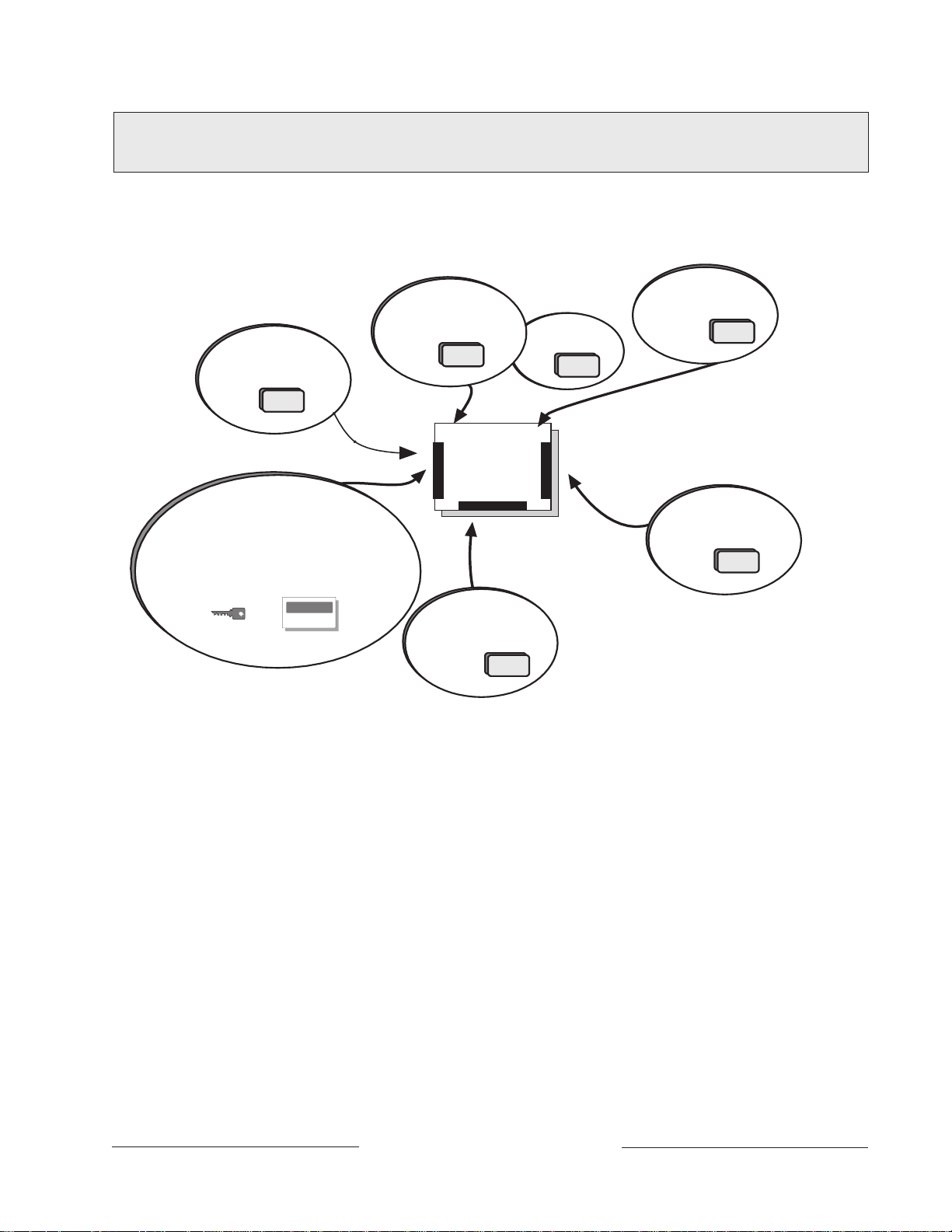
Introduction
D9112
D8128 COctoPOPIT combines
8 POPIT Points in one module.
D8125 Interface for
D8127POPITS
Points 9-71
Use D1255 Command Centers and/or
keyswitches to arm the D9112 by area. Each
panel can have up to 8 areas.Each area can
have its own account number or areas can be
grouped together with a common account number.
Points of protection are assigned to areas.
D128 module allows the
D9112 to monitor two
phone lines.
D9131 module connects
to a parallel printer to
print event log locally.
On-board Points
1 to 8
2nd D8125 adds
Points 73-135
D8129 OctoRelay
provides alarm and
auxiliary relay output.
(Other functions available.)
Points
74-06144-000-C 2/96
Figure 1: D9112 System Configuration
The Radionics D9112 Control/Communicator panel provides up to 134 separate points of
protection. Point programming parameters determine the panel’s response to open and
shorted conditions on the point’s sensor loop. Points are programmed individually with
several options to custom-fit the protection to your installation.
Points 1 to 8 are located on the D9112 circuit board (on-board points). They are standard
sensor loops. The remaining 126 off-board points are POPIT (Point of Protection Input
Transponder) points. Each off-board point requires a POPIT module. D8127 POPIT
modules require the D8125 POPEX module. The D8128A OctoPOPIT module combines
eight POPITs in a single module and does not require the D8125 POPEX module.
D9112 Operation & Installation Manual
Page 7
© 1993 Radionics
Page 8

Areas and Accounts
The D9112 supports up to eight separate areas. You can assign all points to a single
area or spread them out over up to eight areas.
You arm and disarm the D9112 panel by area. You can arm and disarm several areas
with one menu function. You can also assign a passcode an authority level that allows a
user to arm an area from a remote command center in another area. Assigning each
area its own account number creates eight separate accounts in one D9112 panel.
Assigning the same account number to different areas, groups them together in a single
account.
Area options include: exit tone and delay, separate fire and burglary outputs, and multiple
opening and closing windows.
Communicator
The Radionics D9112 Control/Communicator panel uses a built-in digital communicator
to send reports to the receiver. The panel transmits reports in either the Modem II or
BFSK format. Your D6500 receiver's MPU and line cards must have software revision
6.00 (or greater) installed to accept Modem II reports from the D9112. Power your
receiver down and up to print the software revision numbers.
The D9112 connects to an RJ31X jack for phone line seizure. Connection to the RJ31X
complies with FCC regulations for using the public telephone network. You can program
the panel to direct reports to four separate phone numbers. Adding the D128 Dual Phone
Line Switcher module allows you to connect and supervise a second phone line.
D1255 Alpha III Command Center
The D1255 Alpha III Command Center offers complete system control and annunciation.
The D1255 features an illuminated keypad, a 16-character English language display, and
a built-in speaker that offers several distinct warning tones. Switches on the D1255
assign an address (1 to 8) to the command center. You assign addresses to areas in the
Command Center Assignments section of the program.
You can connect a maximum of 32 command centers to the D9112. The available power,
number of supervised command centers, and number of areas you intend to use, affect
the total number of command centers you can connect to the D9112.
The D9112 can supervise up to 8 command centers. The panel transmits a serial device
trouble report, SDI FAILURE in the Modem II format or TROUBLE ZN D in the BFSK
format, if it loses communication with a supervised command center. You can add more
command centers but only eight can be supervised. See Command Center in the D9112
Program Entry Guide (74-06145-000) for complete details on command center options.
Keyswitch
You can arm and disarm any of the eight available areas with maintained or momentary
closure devices such as keyswitches. Keyswitches connect to points. Point programming
determines which area a keyswitch controls. See Options in the Point Index Parameters
module of the D9112 Program Entry Guide (74-06145-000).
D9112 Operation & Installation Manual
Page 874-06144-000-C 2/96
© 1993-1996 Radionics
Page 9

Event Memory
The D9112 uses event memory to store events for each area. You can view the events
for an area at a D1255 Command Center assigned to the area. The D9112 panel clears
the events for an area from event memory and starts storing new events when you
master arm the area.
NCI
154
Event Log
The D9112 stores up to 500 events and event modifiers from all areas in it's event log.
Event modifiers add information about an event to the log. Some events are always
followed by a modifier. For example, the D9112 adds at least two items to the log each
time you arm or disarm an area, the open (or close) event and an event modifier showing
the previous arming state.
All events and their modifiers are stored even if the D9112 does not send a report for
them. You can view the log at a D1255 Command Center, print it locally using the
D9131 Parallel Printer Interface and a parallel printer, or upload it to a D5300 Remote
Account Manager II (RAM II).
See S- View Log in the Security System User's Guide (71-06141-000) for a complete
listing of log events and event modifiers.
EMI/Lightning Transient Protection
The D9112 maintains the Radionics high level of quality and field dependability. Its
design significantly reduces electromagnetic interference and malfunction generally
caused by lightning.
Programming
74-06144-000-C 2/96
Use either the Radionics D5200 Programmer, or the D5300 Remote Account Manager II
(RAM II) to program the D9112. Refer to the D9112 Program Entry Guide (74-06145-000)
for programming options.
D9112 Operation & Installation Manual
Page 9
© 1993 Radionics
Page 10

Other Features
The D9112 has many programmable features. A short list of some of the features follows.
Complete details on all the D9112’s features can be found in the D9112 Program Entry
Guide (74-06145-000).
• Supervision of AC (primary power), battery (secondary power), ZONEX and SDI
• Automatic system test reports
• Remote access for programming, diagnostics, and log uploads using the Radionics
• RAM Line Monitor answering machine work-around
• Fire Alarm Verification
• Programmable Alarm Output
• Programmable Relay Output using the D8129 OctoRelay Module
• Opening and Closing Windows
• Skeds (scheduled events)
buses, CPU (Central Processing Unit), up to 3 printers, and telephone lines
D5300 Remote Account Manager II (RAM II)
D9112 Operation & Installation Manual
Page 1074-06144-000-C 2/96
© 1993-1996 Radionics
Page 11

D9112 Control/Communicator Assembly
The Radionics D9112 Control/Communicator is shipped pre-assembled from the factory.
You should receive the following parts with your D9112 panel.
Literature Pack
• D9112 Installation Reference Guide (74-06144-000)
• D9112 Program Record Sheet (74-06100-000)
• UL Smoke Detector Compatibility Technogram (73-06143-000)
• Point Chart Label (79-06660-000)
• Eight 1k ý end-of-line resistors
• Two 14", 18 AWG, color-coded battery leads
D9112 Assembly:
• D9112 PC board
• Faceplate shield
• Mounting Skirt
• One #6x1¦4" screw
Ordered Separately
Order the following to complete a basic 8 point D9112 installation.
• D1255 Command Center (or keyswitch)
• D1640 Transformer
• D126 Battery
• D161 or D162 Phone Cord
(order two cords if you are using the D128 Dual Phone Switcher)
• D8103, D8109, or D8108A Enclosure
74-06144-000-C 2/96
D9112 Operation & Installation Manual
Page 11
© 1993 Radionics
Page 12

Listings and Approvals
Fire
UL
Underwriters Laboratories lists the D9112 Control/Communicator as a Signal System Control
Unit for:
Central Station, Local, Auxiliary, Remote Station, and Household Fire Warning.
CSFM
Approved by the California State Fire Marshal.
NYC-MEA
Approved by New York City's Materials and Equipment Acceptance System.
Factory Mutual (FM)
Submitted for evaluation by Factory Mutual.
Burglary
UL
Underwriters Laboratories lists the D9112 Control/Communicator for:
Central Station, Local, Police Connect, Mercantile Safe and Vault, and Grade A Household
systems.
Department of Defense (DOD)
The D9112 has been granted approval for Department of Defense (DOD) installations in
Sensitive Compartmented Information Facilities (SCIF).
D9112 Operation & Installation Manual
Page 1274-06144-000-C 2/96
© 1993-1996 Radionics
Page 13
Before You Begin
This
Installation
sections of the manual for detailed instructions.
Radionics recommends you review this manual and the
(74-06145-000) before you begin the installation to determine the hardware and wiring
requirements for the features you want to use.
Have the following additional documents handy as you read through this manual:
•
D9112 Program Record Training Sheet
•
Security System Owner’s Manual
•
D1255 Command Center Installation Manual
Before you begin the installation of the D9112 you should be familiar with the operation of
the D5200 programmer or the RAM II remote programmer.
Enclosure Options
Mount the D9112 Control/Communicator assembly in any of the Radionics enclosures
listed below. Refer to the
determine if your application requires a specific enclosure.
Installation
section contains a general installation procedure. It refers you to other
D9112 Program Entry Guide
(74-06447-000)
(71-06633-000)
(74-06819-000)
Installation Guide for UL and Fire Applications
in this manual to
• D8103 Universal Enclosure (gray)
• D8109 Fire Enclosure (red)
• D8108A Attack Resistant Enclosure (gray)
Beginning the Installation
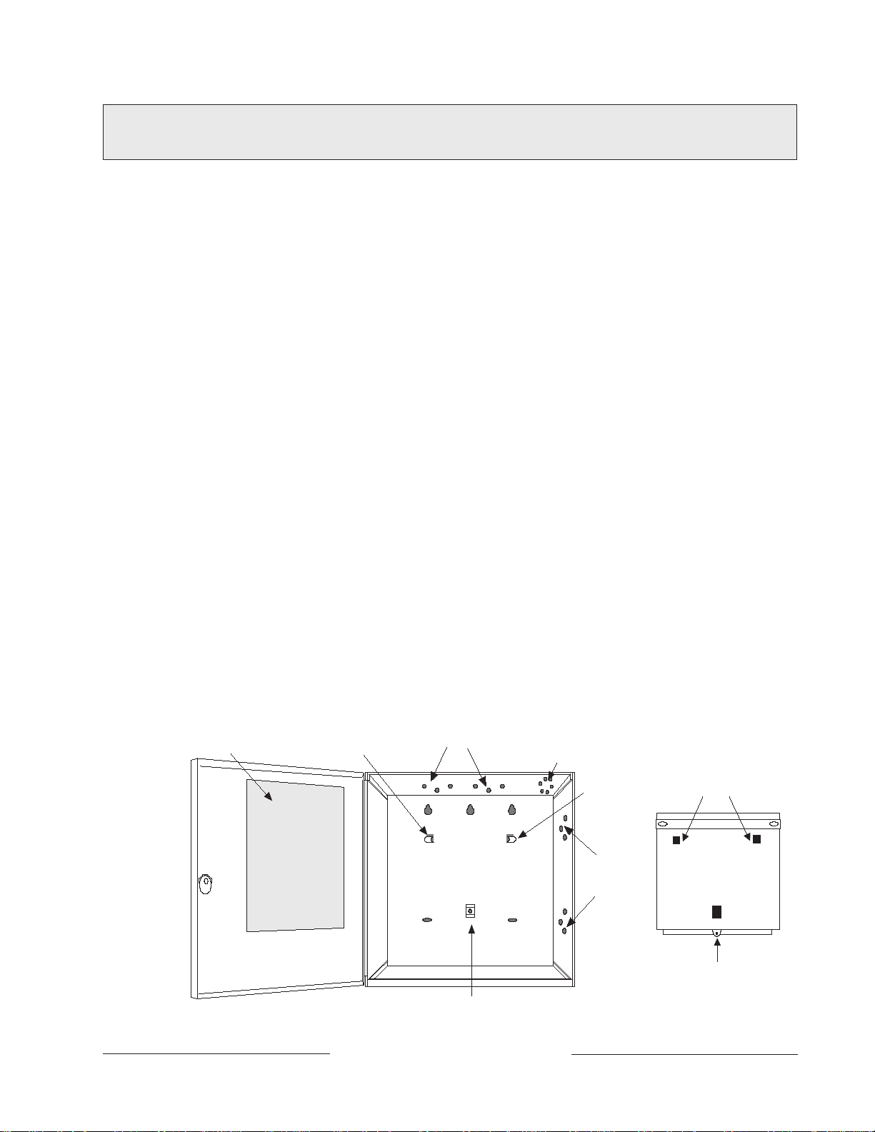
Mounting the Enclosure
Mount the enclosure in the desired location. Be certain to use all five mounting holes. See
Figure 2.
POINT CHART LABEL
MOUNTING
SKIRT HOOK
MODULE MOUNTING
LOCATIONS
TAMPER SWITCH
MOUNTING LOCATION
MOUNTING
SKIRT HOOK
MODULE
MOUNTING
LOCATIONS
HOOK OPENINGS
BACK OF D9112
LOCK-DOWN TAB
74-06144-000-C 2/96
SKIRT MOUNTING HOLE
Figure 2: Enclosure Mounting
D9112 Operation & Installation Manual
Page 13
© 1993 Radionics
Page 14

Premises Wiring
Run the necessary wiring throughout the premises and pull the wires into the enclosure.
EMI (Electro Magnetic Interference) may cause problems: EMI may occur if you
install the D9112 system or run system wires near the following:
• Computer network system
• Electrical lines, fluorescent fixtures or telephone cabling
• Ham radio transmitter site
• Heavy machinery and motors
• High voltage electrical equipment or transformers
• PBX telephone system
• Public service (police, fire departments, etc.) using radio communications
• Radio station transmitter site, or other broadcast station equipment
• Welding shop
If you think that EMI may be a problem, use shielded cable. The drain wire for the
shielded cable must have continuity from terminal 10 on the D9112 to the end of the wire
run. If continuity is not maintained, the shielded cable may aggravate potential noise
problems rather than eliminate them.
Connecting the drain wire to ground at other than terminal 10 may also produce
problems. If you cut the drain wire to install devices be certain to splice it together. Solder
and tape all splices.
Installing the D9112 Assembly
1. Place the D9112 assembly over the inside back of the enclosure, aligning the large
rectangular openings of the mounting skirt with the mounting hooks of the enclosure.
Slide the D9112 down so it hangs on the hooks. See Figure 2.
2. Remove the tape from the #6x1/4" screw in the mounting tab on the D9112
assembly. The screw passes through the mounting tab and into the skirt mounting
hole in the enclosure. Tighten the screw to secure the D9112 assembly in the
enclosure.
3. Connect earth ground to the panel before making any other connections. See Connecting Earth Ground below.
Connecting Earth Ground Terminal 10
To help prevent damage from electrostatic charges or other transient electrical surges,
connect the D9112 to earth ground at terminal 10 before making any other connections.
A grounding rod or cold water pipe are recommended earth ground references.
Do not use telephone or electrical ground for the earth ground connection. Use 16
AWG wire when making the connection. Do not connect any other panel terminals to
earth ground.
D9112 Operation & Installation Manual
Page 1474-06144-000-C 2/96
© 1993-1996 Radionics
Page 15
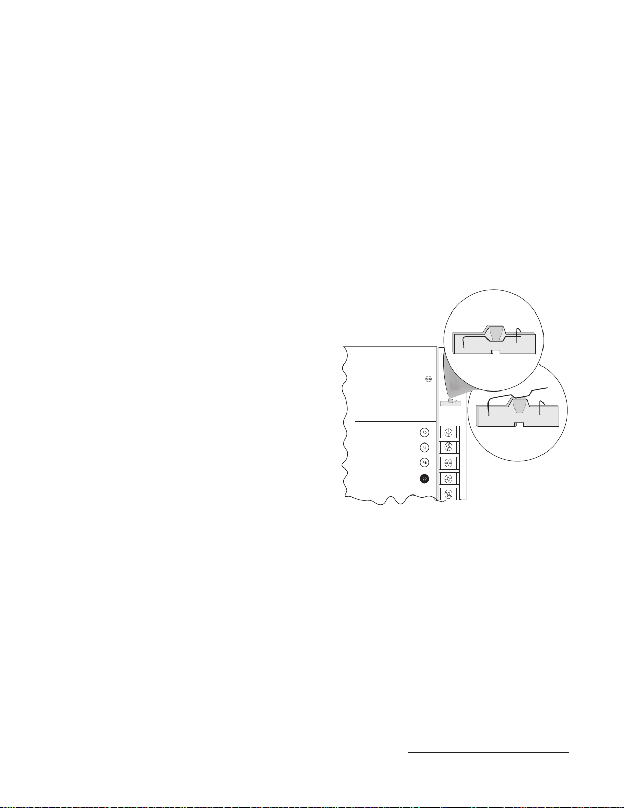
Locking the Reset Pin
RESET PIN
LOCKED (CLOSED)
RESET PIN
NORMAL (OPEN)
Operation Monitor
Pulses When Normal
Flickers When Ringing
Reset Pin
Disable All Except Battery
Charging and Local Programming
RED POWER +
YELLOW DATA BUS A
GREEN DATA BUS B
BLACK COMMON
Locking the Reset Pin disables the panel. See Figure 3. The D9112 ignores the command
centers and points while disabled. CALL FOR SERVICE appears in command center
displays while the pin is locked down.
Existing reports transmitted with Reset Pin locked down:
Any reports that are in the
panel’s report buffer when you lock down the Reset Pin, will be transmitted. However, no
new reports can be created with the pin locked down.
To prevent buffered reports from being transmitted, momentarily close the Reset Pin, wait
for the buzzer to stop sounding, and then lock the pin down to prevent new reports from
being generated.
Locking Reset Speeds Programming:
If you have supervised command centers or
other supervised devices connected to the Data Bus (terminals 30 and 31), locking the
Reset Pin will speed communication between the panel and the D5200.
On-board relays (terminals 6, 7, and 8) and off-board relays,
deactivate when the panel is reset. There is power at
terminal 8 when the relay is deactivated. Activation
interrupts power at that terminal. The relays remain
deactivated while the Reset Pin is
locked in the disable position.
You can program the panel while it
is locked in the disable position with
either the D5200 or D5300 (RAM II)
programmers. If you place the reset
pin in the disable position with one
or more areas disarmed, there must
be an entry in the
Answer Disarmed
program item to use RAM II.
NCI
142,
347, 353
74-06144-000-C 2/96
If you place the reset pin in the
disable position when all areas are
armed, there must be an entry in the
Answer Armed
program item. See
RAM Parameters
in the
Figure 3: Reset Pin
D9112 Program Entry Guide
(74-06145-000).
Releasing the reset pin from the closed position resets the panel. The panel resets all its
timers, counters, indexes, and buffers.
Changes to some program parameters require a reset before they become
effective:
Radionics recommends that you reset the panel after changing program
parameters with the D5200 programmer. The D5300 (RAM II) programmer prompts you
for a "RESET BYE" when a program change requires that the panel be reset.
Lock the Reset Pin Now
Locking the pin in the disable position allows you to power up the panel and charge the
battery as you install the detection devices and command centers. Lock the pin down
now.
D9112 Operation & Installation Manual
Page 15
© 1993 Radionics
Page 16

Finishing the Installation
Earth ground and reset pin first: Make the earth ground connection to terminal 10 and
lock the reset pin in the closed position if you haven’t already done so.
Charge the Battery as You Finish
Connect the battery and then the transformer so that the panel can charge the battery as
you finish the installation. See the Power Supply section for instructions.
On-board Buzzer Sounds at Power Up and Reset: The D9112 performs a series of
self diagnostic tests of its hardware, software, and program at power up and at reset. The
buzzer on the D9112 sounds during the tests. They take about 10 seconds to complete.
If the panel fails any of the tests, the buzzer continues sounding and a system trouble
message appears at the command centers. See Self Diagnostics in the Trouble Shooting
section for a description of each system trouble message.
Touch Terminal 10 first: If the on-board buzzer sounds briefly when you touch the
panel, you're discharging any static charge you may be carrying to the panel. The panel
may generate WATCHDOG RESET and/or PARAM FAIL events. See the Trouble
Shooting section for a description of these events. Always touch terminal 10, the panel's
earth ground connection, before beginning work on the panel.
Install and Wire Detection Devices
Install and wire detection devices and command centers at their locations throughout the
premises. DO NOT make the connections at the panel end of the wiring yet.
The On-Board Points section of this manual contains instructions for wiring the on-board
points to detection devices. The Arming Devices section contains instructions for wiring
the command centers.
Instructions for wiring the off-board point POPIT sensor loops are found in the
instructions packaged with the POPIT modules.
Install Modules and Relays
1. Power Down First: Power down the D9112 by unplugging the transformer and
disconnecting the battery. Radionics recommends that you power down the D9112
when installing modules or relays, or when making wiring connections to the panel.
2. Install and wire any modules required for your installation as described in the
module’s installation instructions.
Instructions for the D8125 POPEX Module, the D8128A OctoPOPIT Module, the
D8129 OctoRelay Module, the D811 Arm Status Relay Module, and the D128 Dual
Phone Line Switcher appear in this manual.
See Off-board Points for D8125 and D8128A instructions. See Relays for D8129 and
D811 instructions. See Dual Line Transmitting in the Telephone Connections section
for instructions for the D128.
3. If you are using the power outputs at terminals 7 or 8, install a D136 relay in the
appropriate sockets. See Programmable Power Outputs in the Power Outputs
section for instructions.
4. If you are using a ground start phone system, insert a D136 relay in socket K6/J5 and
set the ground start pin in the ground start position. See Ground Start in the
Telephone Connections section.
D9112 Operation & Installation Manual
Page 1674-06144-000-C 2/96
© 1993-1996 Radionics
Page 17

Make the Telephone Connections
See Telephone Connections. If you are connecting the D9112 to a ground start phone
system, you need to install D136 relay, see Install Modules and Relays on the previous
page.
Connect the On-Board Points and Command Centers
Connect the on-board point and command center wiring to the D9112. See the On-Board
Points and Arming Devices sections for instructions.
Power Up
Reconnect the battery and then plug in the transformer. Remember the buzzer sounds
for 10 seconds when you first power up the panel.
Leave the reset pin locked down for now.
Yellow Charging Status LED doesn’t go out: If the yellow charging status LED doesn’t
go out within 5 minutes of powering up the panel, the battery may be deeply discharged,
or you may have connected too many powered devices to the panel. Combined
continuous current draw for terminals 3, 8, 24, and 32, the Accessory Connector (J2),
and the Expansion Port (J4) cannot exceed 1.4A. See the Power Outputs section for
help.
Programming the Panel
If you haven’t created a program for the panel, review the D9112 Program Entry Guide
(74-06145-000). Check to be certain you have all the required accessory modules
installed for the features you want to use.
Use the D5200 Programmer or the RAM II remote programmer to load your custom
program into the panel.
Move the reset pin to the normal position. See Figure 3. The panel transmits reboot and
battery reports to the receiver.
Install the Point Chart Label
Radionics recommends you fill out the Point Chart Label (79-06660-000) provided in the
literature pack and install it inside the enclosure doors for all systems.
Point chart label required for fire systems with verification points: You must install
the point chart label for fire or combined fire/burglary systems using verification points.
Use the program record sheet to gather the information you need to fill out the point
chart. Install the label on the enclosure door as shown in figure 2. To avoid smearing your
entries on the chart, use the label's peel off backing to press the label in place.
74-06144-000-C 2/96
D9112 Operation & Installation Manual
Page 17
© 1993 Radionics
Page 18

Testing the System
After finishing the installation and programming of the panel, make a complete functional
test of the D9112 system. Test the panel and all devices for proper operation. Test after
you first program the panel and after any subsequent programming session.
Service Walk Test shows extra points: Use the service walk test at a panel wide
command center to perform a complete test of the panel. The service walk test function is
similar to the ordinary walk test function, with the additional ability to display points that
are not properly programmed.
If you test a POPIT with it’s switches set for a point with a blank point index and/or no
area assignment, it appears as an extra point during a Service Walk Test.
If you test a device, and the panel doesn’t respond, there may be a problem with the
device, the wiring, the POPIT ID setting, or the programming for the point. If you
incorrectly set the switches on a POPIT, you may create both a missing and extra point.
When you find a missing point, performing a service walk test for extra points may help
diagnose the problem.
See the Trouble Shooting Section of this manual for complete service walk test
instructions.
Clear after test: To clear the event memory and report buffer, momentarily close the
reset pin. Events stored in the panel's event log are not cleared.
D9112 Operation & Installation Manual
Page 1874-06144-000-C 2/96
© 1993-1996 Radionics
Page 19

Power Supply
Primary Power Terminals 1 2
Primary (AC) Power Circuit
A 16.5 VAC, 40 VA internally fused transformer (Radionics model D1640) is the primary
power source for the D9112. The AC power circuit provides 1.9 Amps of rectified AC
power. The panel reserves 500 mA of this power for internal operations leaving 1.4 Amps
for powered devices.
Transient suppressors and spark gaps protect the circuit from power surges. This
protection relies on the ground connection at terminal 10. Make sure you connect
terminal 10 to a proper ground. See Connecting Earth Ground in the Installation section.
AC Power Failure
The D9112 indicates an AC power failure when the power at terminals 1 and 2 is missing.
The AC Fail Time program item sets the number of seconds that AC must be missing
before the panel acknowledges the failure and the number of seconds after the power
returns before the panel acknowledges the restoral of power.
You can program AC Fail Time from 1 to 90 seconds. The Radionics default sets AC
Fail Time at 10 seconds.
Installing the Transformer
Do not short the terminals of the transformer: Shorting the terminals opens the
internal fuse causing permanent failure. Connect the transformer to terminals 1 and 2 of
the panel before plugging it into the power source.
Use 18 AWG (minimum) wire to connect the transformer to the panel. Wire length should
be kept as short as possible. Maximum length is 50 feet.
Connect the battery and then plug in the transformer: Radionics recommends that
you always connect the battery first and then plug in the transformer. Instructions for
Installing the Battery appear on the next page.
Only plug the transformer into an unswitched, 120 VAC, 60 Hz power outlet. Secure the
transformer to the outlet with the screw provided.
Never share the transformer with other equipment: Foreign grounds on the AC input
damage the D9112 power circuit.
AC wiring can induce both noise and low level voltage into adjacent wiring. Route phone
and sensor loop wiring away from any AC conductors, including the transformer wire.
Route data wiring away from AC and phone wiring.
D8004 Transformer Enclosure required for fire systems: Use the D8004 Transformer
Enclosure for the D1640 transformer in fire and combined fire/burglary applications.
74-06144-000-C 2/96
D9112 Operation & Installation Manual
Page 19
© 1993 Radionics
Page 20

Secondary Power Terminals 4 5
Secondary (DC) Power
A 12V, 7 Ah sealed lead-acid rechargeable battery (Radionics D126) supplies secondary
power for auxiliary and alarm outputs, and powers the system during interruptions in
primary (AC) power.
Lead Acid Batteries ONLY: The D9112 charging circuit is only calibrated for lead-acid
batteries. Do not use gel-cell or nicad batteries.
Extra Batteries Increase Back-up Time: To increase battery back-up time, connect a
second 12V, 7 Ah battery in parallel to the first battery to form a 12V, 14 Ah battery. Use
a D122 Dual Battery Harness to ensure proper and safe connection. You can use the
D8132 Battery Charger Module to connect two additional batteries for a total of four. See
the D9112 Standby Battery and Current Rating Chart in this manual for battery standby
time calculations.
Installing the Battery
Place the battery upright in the base of the enclosure. Locate the red and black leads
supplied in the literature pack. Connect the black battery lead to terminal 4, and then to
the negative (-) side of the battery. Connect the red battery lead to terminal 5, and then to
the positive (+) side of the battery.
Warning, High Current Arcs Possible: The positive (red) battery lead and Terminal 5
can create high current arcs if shorted to other terminals or the enclosure. Use caution
when working with the positive lead and terminal 5. Always disconnect the positive (red)
lead from the battery before removing it from terminal 5.
Replacement
Radionics recommends battery replacement every 3 to 5 years under normal use.
Exceeding the maximum output ratings, or installing the transformer in an outlet that is
routinely switched off, causes heavy discharges. Routine heavy discharges can lead to
premature battery failure.
D8132 boosts battery backup: Adding a D8132 Battery Charger Module supports
additional batteries of up to 36 Ah capacity if required.
Warning: The transformers for the D9112 and any D8132 modules connected to it must
be powered from the same 120 VAC circuit. The D9112 supervises AC power by
monitoring the power from the transformer connected to terminals 1 and 2. It cannot
supervise the AC power for D8132 modules if their transformers are not plugged into the
same AC circuit as the transformer for the panel.
Battery Supervision
When the battery voltage drops to 13.8 VDC, the yellow Charging Status LED lights.
When the battery drops to 12.1 VDC the red Low Battery LED lights and the panel, if
programmed for power supervision, transmits a BATTERY LOW report in the Modem II
transmission format. It transmits a TROUBLE ZN 9 report in the BFSK format.
If the battery is missing or shorted, the red Low Battery LED flashes at the same rate as
the green Operation Monitor LED. If the panel is programmed for power supervision, it
transmits a BATTERY MISSING report in the Modem II transmission format, or TROUBLE
ZN 9 report in the BFSK format.
D9112 Operation & Installation Manual
Page 2074-06144-000-C 2/96
© 1993-1996 Radionics
Page 21

Battery Supervision (Continued)
When battery voltage returns to 13.7 VDC the Low Battery LED goes out. If the panel is
programmed for power supervision, it transmits a BATTERY RESTORAL report in the
Modem II transmission format or RESTORAL ZN 9 report in the BFSK format. At 13.9
VDC the Charging Status LED goes out.
Investigate low battery reports right away
discharge continues, the panel becomes inoperative when the battery voltage drops
below 10.2 VDC.
: If primary (AC) power is off and the
Battery Charging Circuit
Float Charge
The float voltage for the battery charging circuit is 13.9 VDC at a maximum current of 1.4
Amps. Deduct any continuous load for devices connected to the panel from 1.4 Amps to
find the actual current available for charging.
Load Shed Relay protects battery:
power to the security system. If the battery voltage falls below 10.2 volts during an AC
power loss, a “load shed” relay isolates the battery from the panel and disables the panel.
Load shed protects the battery from being damaged by deep discharge. When AC power
restores, the load shed relay resets and battery voltage is again available.
Reset or power down required for shorted battery:
battery is shorted, it uses the load shed relay to disconnect the battery. You must reset or
power down the panel after correcting the problem to reset the load shed relay and
reconnect the battery.
Reset the panel by momentarily placing the reset pin in the disable position. See Figure
3. The red Low Battery LED continues to flash until you reset the panel.
During an AC power loss the battery supplies all
If the D9112 determines the
Battery Discharge/Recharge Schedule (No AC Power)
74-06144-000-C 2/96
A shorted battery condition is created either by a shorted cell inside the battery or by a
short on terminals 4 and 5. A shorted battery may generate WATCHDOG RESET
reports.
Discharge Cycle
AC OFF AC fail report when AC fails if panel is programmed to report AC failure at
occurrence.
13.9 VDC Charging float level
13.8 VDC Charging Status LED on
12.1 VDC Low Battery & AC fail reports if programmed; Low Battery LED on
10.2 VDC Battery load shed (processing functions continue if AC is present)
Recharge Cycle
AC ON Load shed relay resets, battery charging begins, battery trouble and
AC restoral reports sent.
13.7 VDC Battery restoral reports sent, Low Battery LED off
13.9 VDC Charging Status LED off, battery float charged
D9112 Operation & Installation Manual
Page 21
© 1993 Radionics
Page 22

Charging Status and Low Battery LEDs
Low Battery
LEDs Off When Normal
YEL
RED
Charging Status
Charging Status LED (Yellow)
The yellow LED shows the charging status
of the battery. Figure 4 shows its location.
• Yellow LED off
The yellow LED is off when the battery is
fully charged.
LED off when battery is missing,
shorted, or reversed:
is off when the battery is missing,
shorted, or reversed, but the red Low
Battery LED is flashing.
• Yellow LED on
A steadily lit yellow LED indicates the
battery float voltage is below 13.8. If AC
is present the battery is charging.
The yellow LED also comes on when the combined current draw from all outputs
exceeds 1.4 Amps. This is normal under alarm conditions for non-fire systems when
sirens or bells draw more than 1.4 Amps. If the LED comes on regularly for extended
periods or doesn’t go out, check the current draw for devices connected to the power
outputs. See the
• Yellow LED flashing once per minute
The yellow LED normally flashes once per minute as the D9112 checks the battery.
• Yellow and red LEDs flashing once per minute
The yellow and red LEDs flash on once every minute when current draw for devices
connected to the power outputs exceeds 1.4 Amps and the battery is missing.
The charging LED
Power Outputs
section in this manual for instructions.
Figure 4: Charging and Battery LEDs
74-06144-000-C 2/96
Low Battery LED (Red)
The red LED shows the condition of the battery. Figure 4 shows the location of the LED.
• Red LED off
The red LED is off when the battery is fully charged. When battery voltage drops below
12.1 VDC, the red LED comes on. It goes out when battery voltage reaches 13.7 VDC.
• Red LED on
A steadily lit red LED indicates battery voltage has fallen below 12.1 VDC. The LED
goes out when battery voltage reaches 13.7 VDC.
• Red LED flashing (same rate as green LED)
The red LED flashes with the green Operation Monitor LED when the battery is
missing or shorted.
Reset required for shorted battery:
battery remains disconnected and the red Low Battery LED continues to flash until you
reset the panel.
No missing battery with D192A
from recognizing a missing battery condition.
• Red and yellow LEDs flashing once per minute
The yellow and red LEDs flash once every minute when current draw for devices
connected to the power outputs exceeds 1.4 Amps and the battery is missing.
D9112 Operation & Installation Manual
Page 22
If the D9112 detects a shorted battery, the
Using a D192A with a D9112, prevents the D9112
© 1993-1996 Radionics
Page 23

Circuit Protection
Three self-resetting thermal circuit breakers protect the panel from short circuits on both
the continuous and programmable power outputs. The circuit breakers are thermal rated
and open at 3 to 5 Amps. If the panel is programmed for power supervision and short is
sustained on one of the power outputs, the panel transmits a BATTERY LOW or
BATTERY MISSING for Modem II, or TROUBLE ZN 9 for BFSK.
One thermal circuit breaker protects Terminal 3 - Auxiliary Power and Terminal 24 ZONEX Power and the Expansion Port (J4). A short on one disrupts the power to the
others.
One breaker protects Terminal 6 - Alarm Power Output, Terminal 7 - Alternate Alarm
Power Output, and Terminal 8 - Switched Auxiliary Power. A short on one of these
terminals disrupts the power to the other two.
One circuit breaker protects terminal 32 - Power +.
Power Outputs
Warning, Minimum Requirement for Wire Length:
terminals 3, 6, 7, 8, 24, and 32 with at least 5 feet of 22 AWG wire or 14 feet of 18 AWG
wire. A D9112, with devices connected with shorter lengths of wire, may not operate
properly if AC power is interrupted.
Available Power
The D9112 produces up to 1.4A of power at 10.2 VDC to 13.9 VDC for powered devices.
The outputs listed below share the available power.
Terminal 3 - Auxiliary Power
Use this terminal to power devices requiring continuous power.
Terminal 6 (Relay A) - Alarm Power Output
Terminal 7 (Relay B) - Alternate Alarm Power Output
Use terminals 6 and 7 to power devices requiring power on alarm. See
Power Outputs.
Terminal 8 (Relay C) - Switched Auxiliary Power
Use this terminal to power devices requiring a programmable power interruption.
Command 47 or Alarm Verification interrupts the power . See
Outputs
Terminal 24 - ZONEX Power
Use this terminal to power ZONEX modules such as the D8125, D8128A, and D8129
modules.
Terminal 32 - Power +
Use this terminal to power SDI (Serial Device Interface) devices such as the D1255
Command Center and the D9131 Parallel Printer Interface.
Connect powered devices to
Programmable
Programmable Power
in this manual.
74-06144-000-C 2/96
D9112 Operation & Installation Manual
Page 23
© 1993 Radionics
Page 24

Available Power (Continued)
Accessory Connector (J2)
The D128 Dual Phone Line Switcher connects to J2.
Expansion Port (J4)
The Expansion Port is reserved for future use.
Continuous Power Outputs Terminals 3 24 32
J2 J4
Continuous Current Draw
The continuous current draw for powered devices connected to terminals 3, 8, 24, and
32, the Expansion Port (J4), and the Accessory Connector (J2) must not exceed 1.4A .
Devices powered from these outputs must operate over a range of 10.2 VDC to 13.9
VDC.
Power restricted for fire and combined fire/burglary systems:
Power Formula
systems. See
to calculate the current available for fire and combined fire/burglary
Programmable Power Outputs
.
Use the
Fire System
74-06144-000-C 2/96
D9112 Operation & Installation Manual
Page 24
© 1993-1996 Radionics
Page 25
Programmable Power Outputs Terminals 6 7 8
J1
J9
Programming
The power outputs at terminals 6, 7, and 8 are programmed as relays A, B, and C. All
relays are programmed in the
relay type, Fire Bell for example, when they are assigned to an area. Relays can be
assigned to one or more areas.
The Radionics defaults set relay A (terminal 6) as an Alarm Bell output, relay B (terminal
7) as a Fire Bell output, and relay C (terminal 8) as a Verification/Reset output. The
D9112 Program Entry Guide
programming relays. Descriptions of the functional characteristics of each terminal
appear on the next page.
Relays
module of the program. Relays are assigned a
(74-06145-000) contains complete instructions for
See the
Bell Parameters
section of the program to set the Fire Bell, Alarm Bell output
responses for relays. Four annunciation patterns: Steady, Pulsed, California Standard,
and Temporal Code 3 are available.
Unexpected Output at Terminals 6, 7 and 8:
If terminals 6, 7, and 8 don’t provide the
output you expect:
• Check the programming for relays A, B, and C in the
• Check the
Bell Parameters
section of the program to verify the Alarm and Fire Bell
Relays
module of the program.
responses are programmed for the duration and pattern you expect.
• Check the
Point Assignments
to verify each point is programmed for the local
response you expect.
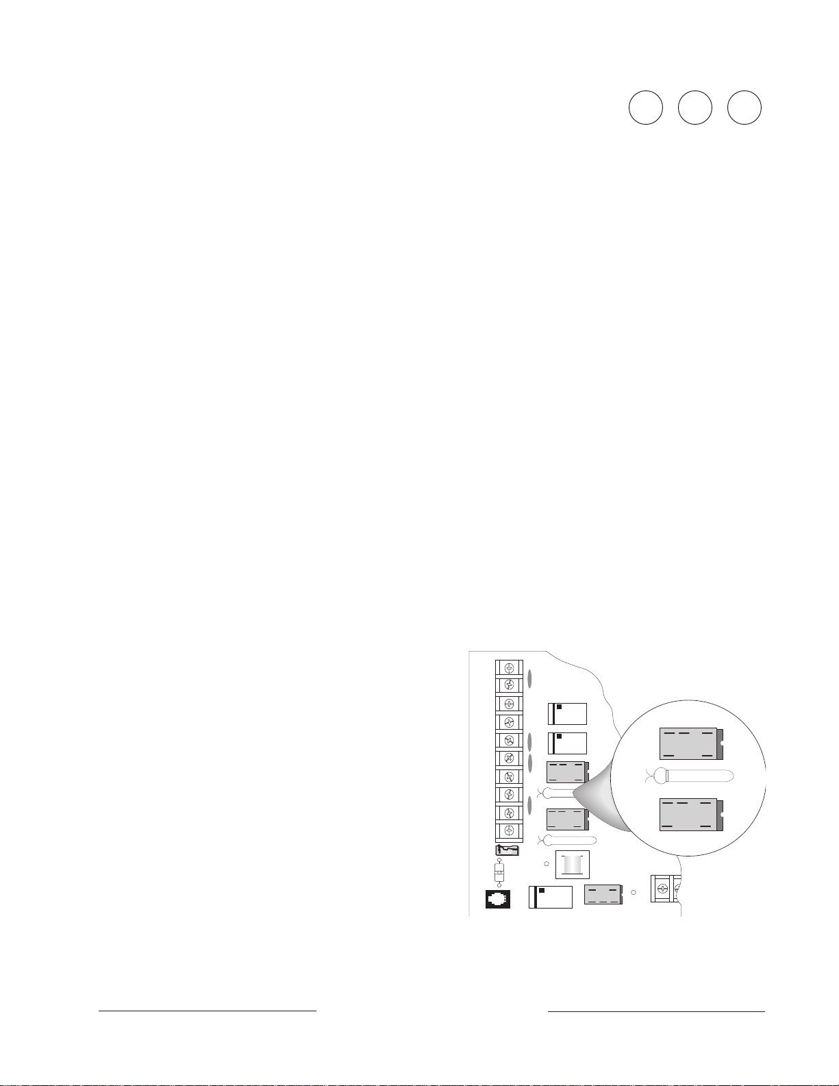
Optional Relays Required
Install an optional D136 plug-in relay into socket J1 to enable the output at terminal 7.
Install a D136 in socket J9 to enable the output at terminal 8. The relay sockets are under
the faceplate as shown in Figure 5.
Relay Installation
Power down the D9112 before
inserting the D136 relays. The plug-
M
in relays are shorter than the
sockets they plug into. See Figure
5. You can install them in either the
left or right end of the socket.
Aromat
DS2E-M-DC12V
M
Aromat
DS2E-M-DC12V
K6
74-06144-000-C 2/96
Don’t rely on relay labelling:
You shouldn’t rely on the labelling
to install D136 relays. Check for the
side with three pins. The three pins
go on the top side.
Incorrect insertion does not
damage the relay or the D9112,
however the related circuits do not
function properly.
D9112 Operation & Installation Manual
Page 25
J1
J9
M
Aromat
DS2E-M-DC12V
GND START
Figure 5: Relays for Terminals 7 and 8
© 1993 Radionics
Page 26

Terminals 6 and 7
Terminals 6 (relay A) and 7 (relay B), provide positive (+) 10.2 VDC to 13.9 VDC power
output when activated. Use the power at terminals 6 and 7 to power bells, siren drivers,
piezo fire sounders, electronic horns, or other devices. Programming determines the
format of the output and the conditions that activate it. One self-resetting circuit breaker
protects terminals 6, 7, and 8 against shorts.
Available Power
The D9112 combines the 1.4A of primary power produced by the power supply with the
secondary power source (the battery) to produce a total of 2.0A of alarm power at 10.2 to
13.9 VDC. Terminals 6 and 7 share the available alarm power.
Power restricted for fire and combined fire/burglary systems:
Power Formula
systems.
below to calculate the current available for fire and combined fire/burglary
Use the
Fire System
Fire System Power Formula
To calculate the current available at terminals 6 and 7 for fire and combined fire/burglary
systems:
1. Add together the current draws for all devices connected to terminals 3, 8, 24, and
32, the Expansion Port (J4), and the Accessory Connect (J2). This total is the total
current required for the Normal Standby Condition (NSC).
2. The current available for Normal Standby Condition (NSC) for the D9112 is 1.4A.
Subtract the NSC current required calculated in step 1 from the NSC current
available, 1.4A. The difference is the Alarm Current available for terminals 6 and 7.
In formula format:
NSC current available – NSC current required = Alarm Current available
Terminal 8
Terminal 8 provides continuous positive (+) 10.2 VDC to 13.9 VDC power. Relay C
interrupts the power at terminal 8 when activated. Use terminal 8 to power smoke
detectors or other devices that are reset by interrupting power. One self-resetting circuit
breaker protects terminals 6, 7, and 8 against shorts.
74-06144-000-C 2/96
Verification/Reset Relay
The D9112 default program sets relay C (terminal 8) as a verification/reset relay. See the
Relay Parameters
(74-06145-000) for instructions on programming verification/reset relays and points.
Performing a CMD 47 at a command center produces a 5 second relay activation of
verification/reset relays. The panel ignores verification/reset points during the 5 seconds
of relay activation.
and
Point Assignments
D9112 Operation & Installation Manual
Page 26
modules in the D9112 Program Entry Guide
© 1993-1996 Radionics
Page 27
Registration
PREMISES
E
Notification
Telephone Connections
The Radionics D9112 Control/Communicator panel is registered with the Federal
Communication Commission under part 68, for connection to the public telephone system
using an RJ31X jack installed by your local phone company.
FCC Registration Number: AJ9USA-18808-AL-E
Ringer Equivalence: 0.1A 0.2B
Do not connect registered equipment to party lines or coin-operated telephones. You
must notify the local telephone company and supply them with the following information
before connecting the panel to the telephone network.
• The particular line you are going to connect the panel to
• Make (Radionics), model (D9112), and serial number of the panel
Location
• FCC registration number and ringer equivalence for the panel (see
above)
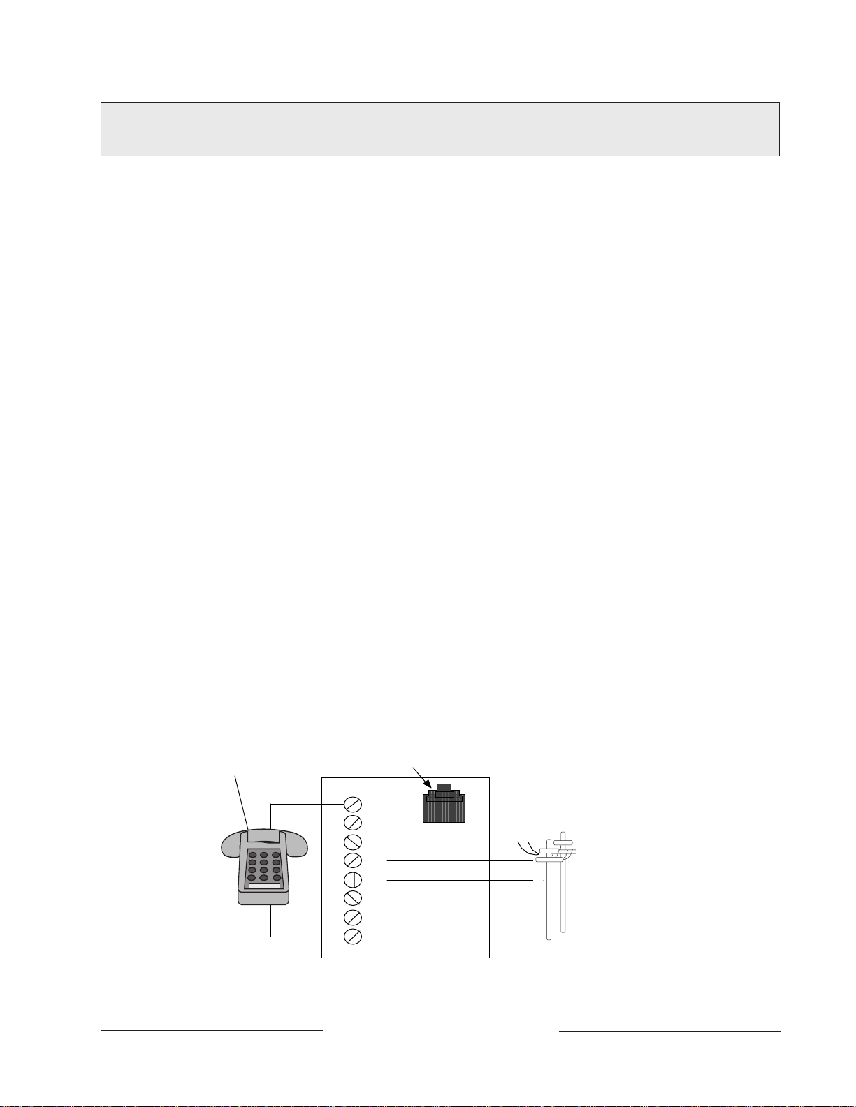
To prevent jamming of signals, wire the RJ31X jack before the in-house phone system to
support line seizure. See Figure 6. Install the jack on the street side of the phone switch,
wired ahead of any PBX equipment. Line seizure provides for a temporary interruption of
normal phone usage while the communicator transmits data. After installation, confirm
that the panel seizes the line, acquires dial tone, reports correctly to the receiver, and
releases the phone line to the in-house phone system.
PHONE
FULL MODULAR PHONE JACK
R1
1
Registration
2
3
R
T
INCOMING
TELCO LIN
%
4
5
6
T1
7
8
74-06144-000-C 2/96
RJ31X MODULE
Figure 6: RJ31X Wiring
D9112 Operation & Installation Manual
Page 27
© 1993 Radionics
Page 28

Phone Cord Connection
Connect one end of a D161 (8') or D162 (2') Telephone Cord to the D9112 TELCO Cord
connector, J3, located on the bottom left corner of the D9112. See Figure 7. Connect the
other end to the RJ31X jack.
Phone LED (Red)
The red Phone LED lights when the panel seizes the phone line and remains lit until the
panel returns the phone line. See Figure 7 for the location of the red LED.
Operation Monitor LED (Green)
The green LED indicates the operation of the CPU (Central Processing Unit). When the
CPU is operating normally, the LED flashes 0.5 second on, 0.5 second off.
The green LED also serves as a ring indicator. See Figure 7 for the location of the LED.
When there is ring voltage on the phone line (the phone is ringing), the green LED
flickers at a faster rate for the duration of each ring. Ring voltage must reach a minimum
of 45 VAC before the D9112 detects it.
Dialing Format
You can program the D9112 to use DTMF or pulse dialing. See
D9112 Program Entry Guide
Phone Line Monitor
The D9112 panel has a built-in phone line monitor that tests the phone line for voltage
and current. If you use the D128 Dual Phone Line Switcher to connect 2 phone lines to
the D9112, the panel monitors both lines. The normal voltage on a telephone line is
approximately 48 VDC (24 VDC for some phone systems). The phone line monitor
senses trouble when the voltage on the line falls below 4.5 to 7.5 VDC, without a
corresponding current increase to 8 to 13 mA.
If the monitor senses trouble, it starts a programmable phone line trouble timer. The timer
continues to run as long as the monitor senses trouble. It resets to zero when the panel
senses a normal line. If the timer reaches the delay time in the
program item, it begins a phone line trouble response. Programming determines what the
response is. See
NCI
#221
The panel stops monitoring the phone line during its phone line trouble response. If the
response includes sending a report, the panel does not resume monitoring until the report
is acknowledged or it goes into communication failure.
Bad line may test OK:
test the status of the phone line. In some instances a given telephone line may be out of
service without affecting the voltage on the line. The phone line monitor can not
recognize this trouble condition.
Phone Parameters
(74-06145-000).
Phone Supervision
Phone Parameters
The telephone line monitor uses voltage and current levels to
in the
D9112 Program Entry Guide
(74-06145-000)
in the
.
74-06144-000-C 2/96
D9112 Operation & Installation Manual
Page 28
© 1993-1996 Radionics
Page 29

Phone Line Test Points
EARTH GROUND
COMMON
LINE SNIFFER SELECT
Loop Start
Ground Start
TELCO CORD
MODEL No. D161
PHONE
LED
ON WHEN
COMMUNICATING
OFF WHEN IDLE
Requires
Optional Relay
Model No. D136
Operation Monitor
Pulses When Normal
Flickers When Ringing
Solid When Held In Reset
32
31
30
+
25
27
28
RED
GROUND
START
YEL
RED
RADIONICS D9112
23
29
26
Reset Pin
Disable All Except Battery
Charging And Local Programming
GRN
+
+
+
24
Also Suitable for Supplementary and Supervisory Electrically Actuated Transmitter Use
ALL TERMINALS EXCEPT #5 (BATTERY POSITIVE) POWER LIMITED
See 73-06143-000 for Compatible Smoke Detectors
12 15 18 211311 14 16 17 19 20 22
3
5
6
7
8
9
10
1
4
2
OPERATION
MONITOR LED
(GREEN)
M
Aromat
DS2E-M-DC12V
You can attach a telephone test set to
the D9112 at the TELTEST points
located above the TELCO jack on the
lower left corner of the panel. See
Figure 7.
Communication Failure
After 10 attempts to reach the
receiver, the panel goes into
communication failure. The
panel clears any reports in its
phone buffer. SERVC COMM
FAIL appears in the display at
command centers.
If you use the D128 Dual Phone Line
Switcher, the D9112 makes 10 attempts on each line before going into communication
failure.
Pressing Command 4 silences the tone. When communication restores (a report is
acknowledged by the receiver), the display clears automatically. See
in the
D9112 Program Entry Guide
PHONE LINE
MONITOR SELECT
JUMPER
PHONE LINE
TELCO CORD
CONNECTOR (J3)
TEST POINTS
M
M
GROUND START
RELAY (J5)
PHONE LED
(RED)
Figure 7: Telephone Connections
Phone Parameters
(74-06145-000) for reporting options
.
Ground Start
74-06144-000-C 2/96
Some telephone systems require a momentary ground input to initiate dial tone. To
interface with a ground start system, insert a plug-in relay (D136) into socket K6/J5 and
set the ground start jumper in the GND START position. Terminal 10 must be connected
to an earth ground reference.
Relay Installation
Power down the D9112 before inserting the D136 relay into socket K6/J5. The relay
socket is in the lower left corner as shown in Figure 8. The plug-in relay is shorter than
the socket it plugs into. You can install it in either the left or right end of the socket.
Don’t rely on relay labeling:
relays. Check for the side with three pins. The three pins go on the top
side.
Incorrect insertion does not damage the
relay or the D9112, however the
related circuits do not function
properly. A ground start relay must
not be inserted when dialing loop
start.
D9112 Operation & Installation Manual
You shouldn’t rely on the labelling to install D136
GROUND START RELAY
Figure 8: Ground Start Relay
Page 29
© 1993 Radionics
Page 30

LINE SNIFFER SELECT
8
9
10
RED
GROUND
START
EARTH GROUND
COMMON
Ground Start
Loop Start
TELCO CORD
MODEL No. D161
Requires
Optional Relay
Model No. D136
M
LOOP START
POSITION
Ground Start Jumper
The ground start jumper is above the TELCO
connector and TELTEST point at the lower left
corner of the panel. Set it in the ground start
position. See Figure 9.
GROUND START
POSITION
Figure 9: Ground Start Jumper
Ground start not for use in NFPA applications:
telephone systems for NFPA 71 Central Station Protective Signaling or NFPA 72 (Chap.
8) Remote Station applications.
D128 Dual Phone Line Switcher
Description
The optional D128 Dual Phone Line Switcher allows the D9112 to transmit reports over a
primary or secondary phone line. The D9112 monitors both phone lines. You can hear a
relay click as the D128 switches between the two phone lines.
Do NOT use the instructions packaged with the D128:
D128 Dual Phone Line Switcher does not include complete instructions for connecting
the module to the D9112 panel. Use the instructions that follow.
Set the ring count above 2 on answering machines:
feature may not operate correctly if you connect an answering machine with a ring count
of less than 2 rings, to a phone line used by the D128 module.
Operation
The D9112 always uses the primary phone line to initiate phone calls, unless it has been
detected as faulty. See
D9112’s phone line monitor operation.
Phone Line Monitor
You can not use ground start
The manual packaged with the
The D9112's RAM Monitor
in this manual for a description of the
74-06144-000-C 2/96
See the
Entry Guide
the
Phone
(74-06145-000) for phone supervision and reporting options. You must set
Two Phone Lines
section of the
Panel Wide Parameters
prompt to YES to use the D128.
D9112 Operation & Installation Manual
Page 30
module of the
D9112 Program
© 1993-1996 Radionics
Page 31

Primary Phone Lines, Primary Phone Numbers
Don’t confuse primary phone lines with primary phone numbers:
Dual Phone Line Switcher installed, the D9112 uses two phone lines, primary and
secondary, to dial up to four phone numbers.
With the D128
These four phone numbers are designated as primary, backup, or duplicate. See
Routing
06145-000) for a description of these designations.
The D128 uses the primary or secondary phone line to dial a primary, secondary, or
backup phone number. After two failed attempts to reach the receiver on the primary
phone line, the D9112 switches to the secondary line.
It alternates between the two phone lines, making two attempts on each line, until it
makes ten attempts on each line. After ten failed attempts on each phone line, the
D9112 goes into communication failure. See
in the
Panel Wide Parameters
module of the
D9112 Program Entry Guide
Communication Failure
in this section.
Watchdog Feature
The D128 Watchdog circuit monitors the D9112’s CPU (Central Processing Unit) for
proper operation. If the CPU fails, the buzzer on the D128 sounds in addition to the
sounder on the D9112. The D128 only stops sounding when the D9112’s CPU begins
operating normally.
Installing the D128
1. Mount the D128 on the lower right side of the enclosure using the screws provided
with the switcher. See Figure 2.
2. Connect the green lead from the D128 to terminal 1 on the D9112.
3. Connect the black lead from the D128 to terminal 9 on the D9112.
4. Plug one end of the ribbon cable provided with the D128 into J4 on the D128. Plug
the other end into J2 (ACCESSORY) on the D9112.
5. Plug one end of the D162 (2') phone cord provided with the D128 into J3 on the
D128. Plug the other end into J3 (TELCO) on the D9112.
6. Plug one end of a D161 (8') or D162 (2') phone cord into J1 on the D128. Plug the
other end into the RJ31X for the primary phone line.
7. Plug one end of a D161 or D162 phone cord into J2 on the D128. Plug the other end
into the RJ31X for the secondary phone line.
Phone
(74-
74-06144-000-C 2/96
D9112 Operation & Installation Manual
Page 31
© 1993 Radionics
Page 32

D128 Status LEDs
Four LEDs mounted on the front edge of the D128 module show the status of AC power
for the D9112, the status of the two phone lines, and communication failure. See Figure
10.
AC Power LED
The green AC power status LED lights when there is AC power at terminals 1 and 2 on
the D9112 panel.
Primary Fail LED
The yellow Primary Fail LED lights when the D9112’s phone line monitor determines the
primary phone line is faulted. See
phone line monitor operation.
Secondary Fail LED
The yellow Secondary Fail LED lights when the D9112’s phone line monitor determines
the secondary phone line is faulted. See
description of phone line monitor operation.
Communication Failure LED
The yellow Communication Failure LED lights when the D9112 is in communication
failure. See
Communication Failure
Phone Line Monitor
Phone Line Monitor
in this section.
in this section for a description of
in this section for a
CONNECT TO D91 12 ACCESSORY
CONNECTOR (J2) WITH RIBBON CABLE
PHONE JACK TO PRIMARY
PHONE LINE - RJ31X
PHONE JACK TO SECONDARY
PHONE LINE - RJ31X
PHONE JACK TO D9112 TELCO
CONNECTOR (J3)
GREEN ÊÑ TO D9112
TERMINAL 1
BLK ÊÑ TO D9112
TERMINAL 9
AC POWER
LED
(GREEN)
PRIMARY
FAIL LED
(YELLOW)
SECONDARY
FAIL LED
(YELLOW)
COMMUNICATIONS
FAILURE LED
(YELLOW)
74-06144-000-C 2/96
Figure 10: D128 Dual Phone Line Switcher
D9112 Operation & Installation Manual
Page 32
© 1993-1996 Radionics
Page 33

On-Board Points
Description Terminals 11 to 22
The D9112 panel provides eight on-board points. Each point functions independently and
does not interfere with the operation of the others. The panel monitors the sensor loops
for normal, shorted, or open conditions between an input terminal (11, 13, 14, 16, 17, 19,
20, or 22) and any of the point common terminals (12, 15, 18, and 21). Programming for
the point determines how the panel responds to those conditions. See the
Program Entry Guide (74-06145-000)
Point Sensor Loops
When wiring the on-board points, install a 1k ý resistor at the far end of the sensor loop
to provide a reference for supervision. You can connect dry contact sensing devices in
series (normally-closed) and/or in parallel (normally-open) to any of these loops.
The number normally-open and/or normally-closed detection devices each sensor loop
can supervise is limited only by the resistance on the loop. Resistance on each sensor
loop must be less than 100ý with the detection devices connected.
for point programming options.
D9112
Ground shunts cause missed alarms:
The possibility of “ground shunts” increases
significantly if you don’t install the resistor at the end of the line. If you install the resistor
for points 1 to 8 before a detection device on the sensor loop and the loop becomes
grounded after the resistor, any devices beyond the ground are “ground shunted”. Alarm
or trouble conditions beyond the ground are not seen by the panel.
POINT INPUT
TERMINAL
1K Ω
COMMON
POINT INPUT
TERMINAL
COMMON
POINT INPUT
TERMINAL
COMMON
NORMALLY CLOSED CONTACTS
NORMALLY OPEN CONTACTS
COMBINATION: NORMALLY OPEN AND
NORMALLY CLOSED CONTACTS
BROWN
BLACK
RADIONICS MODEL
D105F OR D105BL (UL
LISTED BURGLAR
APPLICATIONS)
END-OF-LINE RESISTOR
RED
74-06144-000-C 2/96
Figure 11: On-board Point Sensor Loop Wiring
D9112 Operation & Installation Manual
Page 33
© 1993 Radionics
Page 34

Point Parameters
You can determine the condition of on-board points 1 to 8 by measuring the voltage
across the point input terminal and one of the common terminals. The sensor loops must
be connected and the 1k ý end of line resistor in place.
Open Loop = Greater than 3.7 VDC, but less than 5.0 VDC.
Normal Loop = Greater than 2.0 VDC, but less than 3.0 VDC.
Shorted Loop = Greater than 0.0 VDC, but less than 1.3 VDC.
Point Response Time
The D9112 Control/Communicator scans both on-board and off-board point sensor loops
every 300 milliseconds. The
module determines point response time by setting the number of scans that a point must
be faulted before the panel initiates an alarm.
The debounce count can range from 1 to 15. Therefore point response time ranges from
300 milliseconds to 4.5 seconds. The Radionics default for Debounce Count is 2.
Debounce Count
program item in the
Point Assignment
Warning, increasing debounce count may cause missed alarms:
Debounce Count, detection devices may go into alarm and reset without exceeding the
point response time.
Radionics recommends you leave the debounce count at 2 for all points.
If you increase the
74-06144-000-C 2/96
D9112 Operation & Installation Manual
Page 34
© 1993-1996 Radionics
Page 35

Off-Board Points
Point (ZONEX) Buss Terminals 23 to 28
You can use POPIT (Point of Protection Input Transponder) modules to provide up to
126 off-board points, bringing the total number of points the D9112 can monitor to 134.
Each off-board point requires a POPIT module.
POPITs connect to supervised two-wire data expansion loops run from POPIT to POPIT
throughout the premises. Data expansion loops connect to a D8125 POPEX (Point of
Protection Expander) module. POPEX modules connect to the point buss on the panel,
terminals 23 and 24 for power, and terminals 25 and 26, or 27 and 28 for data.
If a POPIT is disconnected from the expansion loop, a trouble message appears
immediately. See the
options.
If you connect a POPIT that is programmed for a point number that does not appear in
the program for the D9112 to the expansion loop, it appears as an extra point at the
command centers when the point is faulted, and during the service walk test.
Placing a short on the data expansion loop generates a PT BUS TROUBLE report. The
panel sees all points on the shorted expansion loop as shorted, and responds according
to point programming.
D9112 Program Entry Guide
(74-06145-000) for programming
POPIT modules monitor their sensor loops for three conditions, loop normal, loop open,
and loop shorted. They report these three conditions to the D9112. A ground on a POPIT
sensor loop reports as an open.
The D9112 uses point programming to interpret the sensor loop information reported by
the POPITs and make the appropriate system response.
D8125 POPEX Module
D8127 POPIT Modules
D8127 POPITs use the D8125 POPEX module to report to the D9112. Each D8125
supports up to 63 POPIT points. Connect two D8125 modules to the D9112 to bring the
combined total number of POPIT and on-board points to 134. Points 9 to 71 connect to
the first POPEX module. The D9112 reserves Points 72 and 136 for internal use. Points
73 to 135 connect to the second POPEX module. The D9112 only annunciates activity for
each POPIT, not each detection device connected to the sensor loop.
There are two versions of the D8127 modules. Both module enclosures are made of UL
listed fire resistant material. D8127T modules contain tamper switches. D8127U
modules come with an untampered cover. Unless the module is mounted in a tampered
enclosure, UL requires D8127T modules for certificated accounts.
POPEXs manufactured prior to the expiration date (located on the packaging box) of
X9434 may cause POPITs to report as missing after the AC has failed and after the panel
goes into a low battery condition but before the panel goes into load shed. POPEXs
manufactured after X9434 will not cause missing POPITs prior to load shed on an AC
FAIL.
74-06144-000-C 2/96
D9112 Operation & Installation Manual
Page 35
© 1993 Radionics
Page 36

Listings
The D8125 POPEX and D8127 POPIT modules are UL listed for Local or Police
Connected Burglar Alarm, Central Station Burglar Alarm, Household Burglar Alarm,
Central Station Fire (NFPA 71), Local Fire (NFPA 72, Chapter 6), Remote Station Fire
(NFPA 72, Chapter 8), Household Fire (NFPA 74) and Electrically Actuated Transmitter
Applications. See the
determine the required equipment and enclosures for your application.
Installation Guide for UL and Fire
Installing the D8125 POPEX Module
Applications in this manual to
Do not use the instructions packaged with the D8125:
D8125 POPEX module does not include instructions for connecting the module to the
D9112 panel. Follow the instructions below.
Save the D9112 POPIT Label Sheets:
label sheets. One is marked
label the POPITs.
Mounting
Follow the procedure below to install the D8125 in the enclosure with the D9112.
1. Align the D8125 POPEX module with any of the four mounting locations in the
enclosure. See Figure 2.
2. Use the screws provided with the module to secure it in the enclosure.
For use with D9112
The D8125 is packaged with two sets of POPIT
. Save this set. You will use it later to
The manual packaged with the
Wiring the D8125 to the D9112
Follow the procedure below to wire one or two D8125 modules to the D9112.
See Figure 12.
Power down first:
lead at the battery and unplugging the transformer.
Warning, reversed polarity damages the D8125:
D8125 AUX and GND terminals to the D9112.
Power down the D9112 by disconnecting the positive (red) battery
Make sure you correctly wire the
74-06144-000-C 2/96
For points 9 to 71:
1. Connect the GND terminal of the D8125 to terminal 23 on the D9112.
2. Connect the OUT terminal of the D8125 POPEX module to ZONEX IN 1, terminal 27
on the D9112.
3. Connect the IN terminal of the D8125 POPEX module to ZONEX OUT 1, terminal 28
on the D9112.
4. Connect the AUX terminal of the D8125 to terminal 24 on the D9112.
For point numbers from 73 to 135:
1. Connect the GND terminal of the D8125 to terminal 23 on the D9112.
2. Connect the OUT terminal of the D8125 POPEX module to ZONEX IN 2, terminal 25
on the D9112.
3. Connect the IN terminal of the D8125 POPEX module to ZONEX OUT 2, terminal 26
on the D9112.
4. Connect the AUX terminal of the D8125 to terminal 24 on the D9112.
D9112 Operation & Installation Manual
Page 36
© 1993-1996 Radionics
Page 37

Wiring the D8125 to the D9112 (Continued)
T
D8125
T
)
Do not connect more than one D8125 to ZONEX 1, terminals 27 and 28, or ZONEX 2,
terminals 25 and 26.
See
Wiring POPITs to the D8125
POPEX module.
D9112
for instructions on connecting POPITs to the D8125
POPEX
(-)
(-)
(+)
(+)
UP TO 63 POIN
(POINTS 9-71)
ZONEX OUT 1
ZONEX IN 1
ZONEX OUT 2
ZONEX IN 2
ZONEX POWER +
ZONEX COMMON
28
27
26
25
24
23
Figure 12: D8125 Connections
GND
OUT
IN
AUX
(-)
(-)
(+)
(+)
GND
OUT
IN
AUX
UP TO 63 POIN
(POINTS 73-135
74-06144-000-C 2/96
D9112 Operation & Installation Manual
Page 37
© 1993 Radionics
Page 38

Wiring POPITs to the Data Expansion Loop
You can connect up to 63 POPITs to each D8125 module. Use one 2-wire data
expansion loop or distribute the POPITs on up to three loops. Setting DIP switches on the
POPIT modules assigns them to point numbers. See
POPIT Module Point Assignments.
Review
wire is required. Determine the required wire gauge for each data expansion loop using
Table 1.
Combine data expansion loops:
data expansion loops connected to the same POPEX module combined.
Before installing the POPITs, make sure the resistance on the data expansion loop is no
more than 60ý.
Wiring POPITs together:
tap. Doing so may cause random missing POPIT conditions. Follow the procedure below
to connect POPITs to one another in parallel. Figure 13 shows a typical configuration.
1. Connect the positive (+) Data terminal from one POPIT to the positive (+) Data
2. Connect the negative (-) Data terminal from one POPIT to the negative (-) Data
3. Repeat steps 1 and 2 to connect all POPITs to the expansion loop. You don’t need to
Three inch clearance for tampered POPITs:
three inches apart to prevent the tamper magnets from interfering with each other.
Premises Wiring
terminal on the next POPIT.
terminal on the next POPIT.
wire the POPITs in any particular order on the loop. The switch setting on each
POPIT assigns it a point number, regardless of its physical location.
in the
Installation
The maximum lengths shown in Table 1 are for all
Do NOT connect POPITs to each other in series, or with a T-
section of this manual to determine if shielded
Mount tampered POPIT Modules at least
74-06144-000-C 2/96
Maximum Length of All
Data Expansion Loops
Combined
AWG Length (Feet)
22 1,800
20 2,890
18 4,600
16 7,320
14 11,650
Table 1: Data Expansion Loop Wire Specifications
D9112 Operation & Installation Manual
Page 38
© 1993-1996 Radionics
Page 39

D8125
POPEX
MODULE POINTS 9 - 71
(-)
(-)
(+)
(+)
GND
OUT
IN
AUX
D8125
MODULE POINTS 73 - 135
POPEX
(-)
(-)
(+)
(+)
GND
OUT
IN
AUX
Figure 13: Typical Expansion Loop/POPIT Configuration
SWITCHES 1 TO 6
D8127
POPIT
DATA
(-)(+) LOOP
DATA EXPANSION LOOP
DATA
(-)(+) LOOP
DATA EXPANSION LOOP
33K Ω E.O.L.
RESISITOR
NEGATIVE (-)
POSITIVE (+)
SWITCHES 1 TO 6
33K Ω E.O.L.
RESISITOR
NEGATIVE (-)
POSITIVE (+)
DATA
(-)(+) LOOP
DATA
(-)(+) LOOP
DATA
(-)(+) LOOP
DATA
(-)(+) LOOP
DATA
(-)(+) LOOP
UP TO 63 POPITS
DATA
(-)(+) LOOP
UP TO 63 POPITS
Wiring Data Expansion Loops to POPEX Modules
There are two positive (+) and two negative (-) data expansion loop terminals on each
POPEX module. Follow the procedure below to connect the data expansion loops to the
D8125 POPEX Module. See Figure 13. Remember, you can only connect a maximum of
63 POPITs to one D8125.
1. Connect the positive (+) Data terminal from the first POPIT on the data expansion
loop to one of the D8125 module’s positive (+) terminals.
2. Connect the negative (-) Data terminal from the first POPIT on the data expansion
loop to one of the D8125 module’s negative (-) terminals.
POPIT Sensor Loops
The number of normally-open and/or normally-closed detection devices each sensor loop
can supervise is limited only by the resistance on the loop. Resistance on each sensor
loop must be less than 100 ý with the detection devices connected.
Certain UL and NFPA applications may limit the number of detection devices. Consult the
appropriate UL or NFPA standards.
POPITs detect open, shorted, normal, and grounded circuit conditions on their sensor
loops. They transmit the condition of their loops to the D9112. A ground on the sensor
loop reports as a open condition. Each POPIT is programmed and transmits to the D9112
separately.
74-06144-000-C 2/96
Terminate each POPIT sensor loop with the 33k ý end-of-line resistor (Radionics
D106F) included with each POPIT.
Radionics recommends you use twisted-pair wire in all POPEX/POPIT installations for
both the data expansion loop wiring and the POPIT sensor loops. Run wires away from
AC sources to prevent AC induction. If you suspect a noisy environment, use shielded
cable. See
Premises Wiring
in the
Installation
D9112 Operation & Installation Manual
Page 39
section.
© 1993 Radionics
Page 40

Figure 14: D9112 Program Record Sheet
Point Assignments
Six switches on each POPIT assign the module to a point number. POPIT switch settings
are found in the
D9112 Program Record Sheet
The first column on the program record sheet contains the switch settings for the
POPITs. Switches are numbered 1 to 6, left to right. Set switches whose number appears
in the setting to the ON position. Set switches with a dash (-) in the switch position in the
setting to the OFF position. See Figure 14.
The second column contains the translation of the point number into the D8112 ZONEX
format. See
Program Entry Guide
The third column contains the point number as it is displayed at command centers. The
fourth column contains the point index. See the
D9112 Program Entry Guide
The fifth column of the record sheet shows the area the point is assigned to. The sixth
column shows the Debounce Count for the point. See
Assignments
The seventh column shows the BFSK report code. It is the point number reported for this
point when the panel is using the BFSK format. The eighth column contains the text
displayed at command centers for the point. The text is transmitted to the receiver when
the panel is using the Modem II format.
Point Assignment
Point User Flag
(74-06145-000) for an explanation of this feature.
module in the
section of the
in the
Panel Wide Parameters
(74-06145-000) for an explanation of the point index.
D9112 Program Entry Guide
D9112 Program Sheet
module of the
. See Figure 14.
Point Index Parameters
Debounce Count
(74-06145-000).
D9112
module in the
in the
Point
74-06144-000-C 2/96
D9112 Operation & Installation Manual
Page 40
© 1993-1996 Radionics
Page 41

POPIT Labels
1 2 3 4 5 6
ZN 101
PX1
1 2 3 4 5 -
ZN 102
PX1
1 2 3 4 - 6
ZN 103
PX1
1 2 3 4 - -
ZN 104
PX1
1 2 3 - 5 6
ZN 105
PX1
1 2 3 - 5 -
ZN 106
PX1
1 2 - 4 5 6
ZN 109
PX1
1 2 - 4 5 -
ZN 110
PX1
1 2 - 4 - 6
ZN 111
PX1
1 2 - 4 - -
ZN 112
PX1
1 2 - - 5 6
ZN 113
PX1
1 - 3 4 5 6
ZN 201
PX1
1 - 3 4 5 -
ZN 202
PX1
1 - 3 4 - 6
ZN 203
PX1
1 - 3 4 - -
ZN 204
PX1
1 - - 4 5 6
ZN 209
PX1
1 - - 4 5 -
ZN 210
PX1
1 - - 4 - 6
ZN 211
PX1
1 - - 4 - -
ZN 212
PX1
PT 12
PT 11PT 13
PT 17
PT 17
PT 10
PT 10PT 13
PT 19
PT 12
PT 09
PT 09
PT 11
PT 20
PT 18
PT 18
PT 19
PT 20
PT 21
PT 25
PT 25
PT 26
PT 26
PT 27
PT 21
Off-board points are numbered 9 to 71 and 73 to 135. The D9112 reserves points 72 and
136 for internal use. You must connect POPITs for points 73 to 135 to expansion loops
connected to POPEX #2.
Four sheets of peel-off POPIT labels are supplied with the D8125 POPEX module. Use
the sheet marked
Vertical Grid for POPEX #2
Vertical Grid for POPEX #1
for points 73 to 135
for points 9 to 71
.
.
Use the sheet marked
Each label has two parts. Place the smaller part, with just the point number on it, on the
POPIT terminal block as shown in Figure 15. Place the larger part with the switch settings
on the POPIT cover. Set the switches and cover the POPIT.
Do not program two POPITs for the same point number. After you program all the points,
perform a walk test. The
Security System User's Guide
Security System Owner's Manual
(74-06633-000) and the
(71-06141-000) contain instructions for performing a walk
test. If a point does not test, check the programming for a duplicated address.
PT 132
PLACE SMALL
LABEL ON THIS
TERMINAL
BLOCK
1 2 3 4 5 6
74-06144-000-C 2/96
D9112 POINT NUMBER
POPIT SWITCH SETTING
D8112 STYLE ZONEX FORMAT
POPEX MODULE NUMBER
Vertical Grid for POPEX #1
(Use this Vertical Grid for D9112 Points 9 to 71)
D8112
MASTER ZONE 1
D8112
MASTER ZONE 2
Figure 15: POPIT Labels
D9112 Operation & Installation Manual
Page 41
© 1993 Radionics
Page 42

D8128A OctoPOPIT Module
Description
The D8128A OctoPOPIT Module combines the functions of the D8125 POPEX module
and the D8127 POPIT modules to provide eight off-board points in a single module. You
can use OctoPOPIT and D8125 POPEX modules on the same D9112.
Warning, Do not use D8128 modules, they are not compatible with the D9112, only
use D8128A modules:
restoral reports. Be sure to only use D8128A modules.
Using D8128 modules may cause intermittent missing and
Review the
for the OctoPOPITs and other powered devices you wish to connect to your system.
Do not use the instructions packaged with the OctoPOPIT:
with the OctoPOPIT is not for use with the D9112 panel. Use the instructions below.
Power Outputs
section of this manual to be sure you provide enough power
The literature packaged
Listing
The D8128A OctoPOPIT Module is UL listed for Local or Police Connected Burglary
Alarm, Central Station Burglary Alarm, and Household Burglary Alarm applications. The
D8128A is also suitable for fire supervisory applications, such as indicating circuit
supervision (using the D192A Bell Circuit Supervision Module), sprinkler supervision, and
valve tamper protection. Do not connect fire alarm initiating devices to the D8128A
You must use the D125B Powered Loop Interface Module or D129 Dual Class A initiation
Circuit Module for fire initiation applications. Connect the initiating devices, smoke
detectors for example, to the D125B powered loops or D129 Class A loops.
Connect the zone outputs on the D125B or D129 to the OctoPOPIT sensor loop inputs.
The D125B or D129 and the OctoPOPIT must be mounted in the enclosure with the
D9112 or in an enclose connected to the D9112’s enclosure by conduit not more than 20
feet in length.
Installing the OctoPOPIT
You can install the D8128A OctoPOPIT Module in the enclosure with the D9112, or in a
separate enclosure up to 200 feet from the panel. If you mount the OctoPOPIT in a
separate enclosure, use shielded cable to avoid electro-magnetic interference. See
on Long Wire Runs
in the
Troubleshooting
section of this manual.
EMI
74-06144-000-C 2/96
Tampered enclosures for UL certificated systems:
enclosure for UL certificated systems.
Mounting
Follow the procedure below to install OctoPOPITs in the enclosure with the D9112.
1. It is easier to set the switches on the D8128A before you mount it in the enclosure.
See
Line Termination, Sensor Loop Switches,
2. Align the OctoPOPIT module with any of the four mounting locations in the enclosure.
See Figure 2.
3. Use the screws provided with the module to secure it in the enclosure.
Use the D137 Mounting Bracket to install OctoPOPITs in enclosures with no module
mounting locations available.
D9112 Operation & Installation Manual
Page 42
Mount the D8128A in a tampered
and
Point Assignment Switches.
© 1993-1996 Radionics
Page 43

Wiring OctoPOPITs to the D9112
ZONEX OUT 1
ZONEX IN 1
ZONEX OUT 2
ZONEX IN 2
ZONEX POWER +
ZONEX COMMON
D9112
28
27
26
25
24
23
Follow the procedure below to wire D8128A OctoPOPIT Modules to the D9112. You can
connect OctoPOPIT and POPEX modules to the same Point Buss terminals. The
modules wire in parallel. Remember you can never assign the same point number to
more than one point.
1.
Power down first:
battery lead at the battery and unplugging the transformer.
2. Connect terminal 1 on the OctoPOPIT to terminal 23 on the D9112.
3. Connect terminal 2 on the OctoPOPIT to
terminal 28 on the D9112 if you are going to
assign point numbers from 9 to 71 to this
OctoPOPIT. See
Assignments.
If you are assigning point
numbers from 73 to 135,
connect terminal 2 on the
OctoPOPIT to terminal 26
on the D9112.
Power down the D9112 by disconnecting the positive (red)
P O I N T S
1 2 3 4 5 6 7 8 9 10 11 12
D8128A OCTOPOPITS
FOR POINTS 9 - 71
CONNECT MULTIPLE
OCTOPOPITS IN
PARALLEL.
CONNECT OCTOPOPITS
AND THE D8125 POPEX
MODULE IN PARALLEL.
OctoPOPIT Point
SENSOR
LOOPS
4
TO CONTROL
12
31 ZX 3
34
P1
567 89
COM
P2
P3
COM
P4
10 11 12
P5
COM
P6 P7
13 14
COM
15 16
P8
Z O N E
123456789101112
N
O
74-06144-000-C 2/96
4. Connect terminal 3 on the
OctoPOPIT to terminal 27
on the D9112 if you are
going to assign point
numbers from 9 to 71 to
this OctoPOPIT.
If you are assigning point
numbers from 73 to 135,
connect terminal 3 on the OctoPOPIT
to terminal 25 on the D9112.
5. Connect terminal 4 on the OctoPOPIT
to terminal 24 on the D9112.
6. See
OctoPOPIT Sensor Loops
for
instructions on connecting devices to the
OctoPOPIT’s sensor loops.
Figure 16: D8128A OctoPOPITs
D9112 Operation & Installation Manual
Page 43
SENSOR
LOOPS
4
TO CONTROL
12
31 ZX 3
34
P1
567 89
COM
P2
P3
COM
P4
10 11 12
P5
COM
P6 P7
13 14
COM
15 16
P8
Z O N E
P O I N T S
123456789101112
N
O
1 2 3 4 5 6 7 8 9 10 11 12
D8128A OCTOPOPITS
FOR POINTS 73 - 135
CONNECT MULTIPLE
OCTOPOPITS IN
PARALLEL.
CONNECT OCTOPOPITS
AND THE D8125 POPEX
MODULE IN PARALLEL.
© 1993 Radionics
Page 44

Line Termination
If there is no D8125 POPEX module connected to ZONEX 1, terminals 27 and 28, set
switch 12 on only one OctoPOPIT connected to those terminals to the on position.
If there is a D8125 POPEX module connected to ZONEX 1, terminals 27 and 28, set
switch 12 on all OctoPOPITs connected to those terminals to the off position.
If there is no D8125 POPEX module connected to ZONEX 2, terminals 26 and 25, set
switch 12 on only one OctoPOPIT connected to those terminals to the on position.
If there is a D8125 POPEX module connected to ZONEX 2, terminals 26 and 25, set
switch 12 on all OctoPOPITs connected to those terminals to the off position.
See Figure 16 for the location of the switches on the OctoPOPIT.
74-06144-000-C 2/96
D9112 Operation & Installation Manual
Page 44
© 1993-1996 Radionics
Page 45

OctoPOPIT Sensor Loops
The number normally-open and/or normally-closed detection devices each sensor loop
can supervise is limited only by the resistance on the loop. Resistance on each sensor
loop must be less than 100ý with the detection devices connected.
Certain UL and NFPA applications may limit the number of detection devices. Consult the
appropriate UL or NFPA standards.
The OctoPOPIT detects open, short, closed, normal, and grounded circuit conditions on
its sensor loops and transmits the conditions to the D9112. A ground on the positive leg
of the sensor loop transmits a shorted condition for the point. Each sensor loop is
assigned a point number and transmits to the D9112 separately. See
Switches
Radionics recommends you use twisted-pair wire for the OctoPOPIT sensor loops to
avoid EMI problems. Run wires away from the premises telephone and AC wiring. If you
suspect a noisy environment, use shielded cable. See
Troubleshooting
There are two rows of terminal numbers on the D8128A. See Figure 16. In the row
closest to the terminal blocks, the positive outputs for the sensor loops are labeled
P8
. Sensor loop outputs P1 and P2, P3 and P4, P5 and P6, and P7 and P8 share
common terminals. The common terminals for each pair are labelled
Sensor Loop Switches
Switches 1 to 8 activate each of the eight OctoPOPIT sensor loops. Setting the switch
ON enables reports from that sensor loop. Setting the switch to OFF disables the loop. If
you disable a sensor loop assigned to a point that the D9112 expects to see, the D9112
interprets it as a missing point.
below.
EMI on Long Wire Runs
section.
Point Assignment
in the
COM.
P1
to
NCI
#215
Always set the Sensor Loop switch for points 72 and 136 to OFF:
reserves points 72 and 136 for internal functions. Set switch P8 to OFF to disable the
sensor loop for those points. Setting P8 to ON for points 72 and 136 may cause
erroneous PT BUS TROUBLE reports.
Switch 1 corresponds to sensor loop 1 (terminal P1), switch 2 corresponds to sensor loop
2 (terminal P2), and so on.
Terminate each OctoPOPIT sensor loop with a 1k ý end-of-line resistor. Attach a resistor
even if you don’t enable the loop. The OctoPOPIT comes with a Radionics D105BL
resistor for each sensor loop.
Point Assignment Switches
Switches 9, 10 and 11 on the OctoPOPIT assign the sensor loops to D9112 point
numbers. Table 2 shows the OctoPOPIT switch settings for point assignments. Each
setting assigns point numbers to all eight sensor loops. Set the sensor loop switches (1 to
8) to OFF for points on the OctoPOPIT you don’t intend to use.
Duplicated points do not function correctly:
assignments. Points assigned to both an OctoPOPIT sensor loop and a POPIT, two
OctoPOPIT sensor loops, or two POPITs, do not function properly.
Take care not to duplicate point
The D9112
D9112 Operation & Installation Manual
Page 45
© 1993-1996 Radionics74-06144-000-C 2/96
Page 46

Table 2:
(
D8128A OctoPOPIT
Switch Settings
D8128A
Switches
91011
D8128A
Sensor Loop
D9112 Point #
Connect D8128A
to ZONEX 1
D9112 Point #
Connect D8128A
to ZONEX 2
74-06144-000-C 2/96
NCI
#215
P1
P2
P3
P8
P4
P5
P6
P7
P8
P1
P2
P3
P4
P5
P6
P7
P8
P1
P2
P3
P4
P5
P6
P7
P8
P1
P2
P3
P4
P5
P6
P7
P8
P1
P2
P3
P4
P5
P6
P7
P8
P1
P2
P3
P4
P5
P6
P7
P8
P1
P2
P3
P4
P5
P6
P7
P8
P1
P2
P3
P4
P5
P6
P7
set to
72 used
On On On
On On Off
On Off On
On Off Off
Off On On
Off On Off
Off Off On
Off Off Off
D9112 Operation & Installation Manual
Page 46
10
11
12
13
14
15
16
17
18
19
20
21
22
23
24
25
26
27
28
29
30
31
32
33
34
35
36
37
38
39
40
41
42
43
44
45
46
47
48
49
50
51
52
53
54
55
56
57
58
59
60
61
62
63
64
65
66
67
68
69
70
71
9
73
74
75
76
77
78
79
80
81
82
83
84
85
86
87
88
89
90
91
92
93
94
95
96
97
98
99
100
101
102
103
104
105
106
107
108
109
110
111
112
113
114
115
116
117
118
119
120
121
122
123
124
125
126
127
128
129
130
131
132
133
134
135
136 used
© 1993-1996 Radionics
internallyinternallyOFF)
Page 47

Testing Off-board Points
Use the Service Walk Test item from the command center Service Menu to test off-board
points. See the
instructions.
Service Walk Test
in the
Troubleshooting
section of this manual for
Walk test does not show extra points:
If you incorrectly set the point assignment switches on a POPIT or OctoPOPIT, you may
create both missing and extra points. If you assign the same point number to two or more
POPITs or OctoPOPITs, none of the points with that number will test correctly.
Test to be sure that all off-board points operate properly.
Only the Service Walk Test shows extra points.
D9112 Operation & Installation Manual
Page 47
© 1993-1996 Radionics74-06144-000-C 2/96
Page 48

D8129 OctoRelay
The D8129 OctoRelay allows you to add relay outputs to your system in groups of eight.
Up to 128 OctoRelay outputs (relay numbers 1 to 128) can be added to your system
using 16 OctoRelays. Review the
provide enough power for the OctoRelays and other powered devices you wish to
connect to your system.
OctoRelays for relay numbers 1 - 64 connect to ZONEX 1, terminal 28 on the D9112.
OctoRelays for relay numbers 65-128 connect to ZONEX 2, terminal 26 on the D9112.
See Figure 17.
You can assign alarm output, auxiliary relay, sensor reset, arming status, point status,
alarm memory, or remote functions (Command 54) to the OctoRelay outputs individually.
See
programming details.
Off-board Relays
Relay Parameters
in the
Power Outputs
D9112 Program Entry Guide
section of this manual to be sure you
(74-06145-000) for
D8129 restricted for fire systems:
can not be used in fire or combined fire/burglary installations for primary indicating
devices.
The D8129 relay outputs are not supervised and
Configuring the D8129 OctoRelay
Five switches on the OctoRelay determine the relay numbers for the eight relay outputs.
Table 3 shows the switch settings.
Warning:
programming the panel. You may wish to disconnect equipment connected to relay
outputs while performing these functions.
Relay outputs may activate while setting the OctoRelay switches or
Relay Outputs
Each OctoRelay output provides a Form C dry contact rated for 1.0A at 12 VDC.
Normally-open, common, and normally-closed terminals are available for each relay
output. When an individual output is activated, there is continuity between the normallyopen and common terminals. When the output is not activated, there is continuity
between the normally-closed and common terminals.
74-06144-000-C 2/96
D9112 Operation & Installation Manual
Page 48
© 1993-1996 Radionics
Page 49

D9112
Relay Number
D8129 OctoR elay
Switch Setting
On D9112, connect
D8129 to
1 to 8 Off-On -On-On -On
9 to 16 On- Off-On-On-On
17 to 24 Off- Off-On-On-On
25 to 32 On- On-Off-On-On
33 to 40 Off- On-Off-On-On
41 to 48 On- Off-Off-On-On
49 to 56 Off- Off-Off-On-On
57 to 64 On- On-On-Off-On
65 to 72 Off-On-On-On-On
73 to 80 On- Off-On-On-On
81 to 88 Off- Off-On-On-On
ZON EX 1
Terminal 28
ZON EX 1
Terminal 28
ZON EX 1
Terminal 28
ZON EX 1
Terminal 28
ZON EX 1
Terminal 28
ZON EX 1
Terminal 28
ZON EX 1
Terminal 28
ZON EX 1
Terminal 28
ZON EX 2
Terminal 26
ZON EX 2
Terminal 26
ZON EX 2
Terminal 26
89 to 96 On- On-Off-On-On
97 to 104 Off- On-Off-On-On
105 to 11 2 On- Off-Off-On-On
113 to 12 0 Off- Off-Off-On-On
121 to 12 8 On- On-On-Off-On
Table 3: D8129 Switch Settings
D9112 Operation & Installation Manual
Page 49
ZON EX 2
Terminal 26
ZON EX 2
Terminal 26
ZON EX 2
Terminal 26
ZON EX 2
Terminal 26
ZON EX 2
Terminal 26
© 1993-1996 Radionics74-06144-000-C 2/96
Page 50

Installation
1234567 8
DATA
AUX
GND
1234567 8
DATA
AUX
GND
ZONEX OUT 1
ZONEX IN 1
ZONEX OUT 2
ZONEX IN 2
ZONEX POWER +
ZONEX COMMON
D9112
28
27
26
25
24
23
Do not use the instructions packaged with the D8129:
instructions for connecting the module to the D9112 panel. Follow the instructions below.
They do not include
Set the switches on the OctoRelay before you install it in the enclosure. See
the D8129 OctoRelay
. You can install the OctoRelay in the enclosure with the D9112
Configuring
(see Figure 2) or in an adjacent enclosure not more than 5 feet from the D9112. Use 16
to 22 AWG wire.
Follow the procedure below to install OctoRelays in the enclosure with the D9112.
1. Align the module with one of the mounting locations in the enclosure. See Figure 2.
2. Use the screws provided with the module to secure it in the enclosure.
Use the D137 Mounting Bracket to install OctoRelays in enclosures with no module
mounting locations available.
Wiring Connections
Power down the panel to connect OctoRelays as shown in Figure 17. Note that
OctoRelays for relay numbers 1 to 64 connect to ZONEX 1, terminal 28 on the D9112.
OctoRelays for relay numbers 65 to 128 connect to ZONEX 2, terminal 26 on the D9112.
Only one OctoRelay is shown wired to each ZONEX bus in Figure 17. Wire additional
OctoRelays in parallel. Review the
provide enough power for the relays.
D8125
POPEX
(-)
(-)
(+)
(+)
Power Outputs
section of this manual to be sure you
74-06144-000-C 2/96
GND
OUT
IN
AUX
(-)
(-)
(+)
(+)
GND
OUT
IN
AUX
Figure 17: D8129 OctoRelay Connections
D9112 Operation & Installation Manual
Page 50
D8129 OCTORELAYS FOR RELAY
NUMBERS 1 TO 64. CONNECT
OCTORELAYS IN PARALLEL.
D8129 OCTORELAYS FOR RELAY
NUMBERS 65 TO 128. CONNECT
OCTORELAYS IN PARALLEL.
© 1993-1996 Radionics
Page 51

D811 Arm Status Relay Module
The 811 Arm Status Relay Module allows you to add a single off-board relay output to
your system. When used with the D9112 you can assign alarm output, auxiliary relay,
sensor reset, arming status, point status, alarm memory, or remote functions (Command
54) to the D811 relay output. You are not restricted to the arming status mode only.
Relay numbers for D811 not programmable:
terminal 28 on the D9112, you must use relay number 53 for the relay output. If you
connect the D811 to ZONEX 2, terminal 26 on the D9112, you must use relay number
117 for the relay output.
D811 modules connect as shown in Figure 18. Review the
manual to be sure you provide enough power for the powered devices you wish to
connect to your system. See
06145-000) for programming details.
D811 restricted for fire systems:
be used in fire or combined fire/burglary installations for primary indication devices.
Relay Parameters
The D811 relay output is not supervised and can not
If you connect the D811 to ZONEX 1,
in the
Power Outputs
D9112 Program Entry Guide
section of this
Relay Output
Each D811 relay output provides a Form C dry contact rated for 1.0A at 12 VDC.
Normally-open, common, and normally-closed terminals are available. When an
individual output is activated, there is continuity between the normally-open and common
terminals. When the output is not activated, there is continuity between the normallyclosed and common terminals.
Warning:
disconnect equipment connected to relay outputs while performing these functions.
Relay outputs may activate while programming the panel. You may wish to
Installation
Do not use the instructions packaged with the D811:
the D811 module is not for use with the D9112 panel. Use the instructions below.
The literature packaged with
(74-
You can install the D811 in the enclosure with the D9112 (see Figure 2) or in an adjacent
enclosure not more than 5 feet from the D9112. Use 16 to 22 AWG wire.
Follow the procedure below to install D811 modules in the enclosure with the D9112.
1. Align the D811 module with any of the four mounting locations in the enclosure. See
Figure 2.
2. Use the screws provided with the module to secure it in the enclosure.
Use the D137 Mounting Bracket to install D811 modules in enclosures with no module
mounting locations available.
D9112 Operation & Installation Manual
Page 51
© 1993-1996 Radionics74-06144-000-C 2/96
Page 52

Wiring Connections
Power down the panel to connect D811 modules as shown in Figure 18. Note that the
D811 for relay number 53 connects to ZONEX 1 on the D9112. The D811 for relay
number 117 connects to ZONEX 2 on the D9112.
D8125
POPEX
(-)
(-)
(+)
D9112
ZONEXOUT 1
ZONEXIN 1
ZONEXOUT 2
ZONEXIN 2
ZONEXPOWER +
ZONEXCOMMON
(+)
GND
OUT
IN
28
AUX
DATA
D811 FOR RELAY NUMBER 53
AUX
GND
27
26
25
24
23
5
(-)
(-)
(+)
(+)
GND
OUT
AUX
IN
DATA
AUX
GND
Figure 18: D811 Module Wiring
5
D811 FOR RELAY NUMBER 117
74-06144-000-C 2/96
D9112 Operation & Installation Manual
Page 52
© 1993-1996 Radionics
Page 53

Arming Devices
Description
Command centers, maintained or momentary contact keyswitches, or a combination of
the two are used to arm and disarm areas. The D9112 panel may contain up to 8 areas.
See the
D1255 Command Centers Terminals 29 to 32
The Radionics D1255 Command Center is a 4-wire powered device used to arm and
disarm areas, annunciate complete system status, initiate system tests, and control many
functions of the D9112 security system.
The D9112 can supervise up to eight command centers. The panel transmits a serial
device trouble report, SDI FAILURE in the Modem II format or TROUBLE ZN D in the
BFSK format, if it loses communication with a supervised command center. SERVC
KEYPAD appears at all other command centers connected to the system.
You can connect up to 32 command centers to the D9112 but they all can not be
supervised. The number of supervised command centers, number of areas, and the
available power determine the total number of command centers you can connect to the
D9112. See
complete programming details on command center options.
Introduction
section for a description of areas.
Command Center
in the
D9112 Program Entry Guide
(74-06145-000) for
NCI #40
NCI
#292
CALL FOR SERVICE appears in the display of any command center that loses
communication with the panel.
See the
Guide
Security System Owner’s Manual
(71-06141-000) for operational information.
(71-06633-000) or
Security System User’s
Assigning the D1255 an Address
Switches on the D1255 assign an address (1 to 8) to the command center. The address
determines if the command center is supervised, the command center's scope, and what
area the command center is assigned to. See
D9112 Program Entry Guide
Table 4 shows the correct switch setting for each address.
Address #1
Address #2
Address #3
Address #4
Address #5
Address #6
Address #7
Address #8
(74-06145-000) for a complete description of addresses.
1
ON ON ON ON ON
OFF
ON ON ON ON
OFF
OFF OFF
ON ON ON ON
ON ON ON
OFF OFF
OFF OFF OFF
Command Center Assignment
Switch
23
ON ON ON ON
ON ON ON
OFF
ON ON ON
OFFOFF
4
56
ENCODING TONE ON/OFF
ON ON
in the
Table 4: D1255 Address Settings
D9112 Operation & Installation Manual
Page 53
© 1993-1996 Radionics74-06144-000-C 2/96
Page 54

Installation
Consult the
instructions. Command centers connect to the D9112 panel in parallel as shown in
Table 5.
D1255 Installation Instructions
(74-06819-000) for installation and mounting
D9112 Command Center
Terminal Function Wire Color Function
32 * POWER + Red 12 VDC
31 DATA BUS A Yellow Data-In
30 DATA BUS B Green Data-Out
29 COMMON Black Common
*Connect with at least 5' of 22 AWG wire (14' of 18 AWG wire)
Table 5: D1255 Connections
NCI
#1,
#40
Switching the green and yellow wires affects other command centers:
connecting the green wire from the command center to the D9112's terminal 31 and the
yellow wire to terminal 30, causes other command centers connected to the panel to go
blank and/or sound random beep tones.
You can connect a maximum of 15,000 feet of 22 AWG wire
and printer modules combined
parallel wire runs from the D9112 to each device, run wire device to device, or combine
the two.
Extra power needed for more command centers:
draws 104 mA when it is idle. It draws 206 mA with the back lighting for the keys lit and
the sounder activated. Review the
output requirements for your system.
You may need to add one or more D8132 Battery Charger/Power Supply Modules for the
number of command centers you want to use. Figure 19 shows the D8132 powering
command centers in a stand-alone configuration.
For UL certificated accounts use a UL listed power supply. The D8132 is not UL listed as
a stand-alone power supply.
to the data bus, terminals 30 and 31. You can connect
The D1255 Command Center
Power Outputs
section to determine the total power
for all command centers
D9112 and D8132 (or other power supply) must share COMMON:
19 shows the common from the D8132 module connected to both the command centers'
common and the common on the D9112.
Incorrectly
Note that Figure
74-06144-000-C 2/96
A stand-alone power supply powering any device connected to the D9112 must also be
connected to a common terminal on the D9112. Do not connect the stand-alone power
supply to earth ground other than terminal 10 on the D9112.
D9112 Operation & Installation Manual
Page 54
© 1993-1996 Radionics
Page 55

ED
EEN
32
POWER +
DATA BUS A
DATA BUS B
COMMON
31
30
28
29
Charging And Programming
D9112
Figure 19: Power at Command Centers
D268/D269 Independent Zone Control
D279 Independent Zone Control
+12VDC
DATA
D8132
+12VDC
COMMON
DATA
COMMON
You can program any
on-board
or
OctoPOPIT
point so that the D268/D269 or D279
Independent Zone Control operates as independent point control (arms and disarms the
point).
See the
programming information. See the
(74-04758-000) or the
Point Assignments
D279 Operation and Installation Instructions
in the
D9112 Program Entry Guide
D268/D269 Operation and Installation Instructions
(74-06145-000) for
(74-04993-000) for
wiring and operation instructions.
D9112 Operation & Installation Manual
Page 55
© 1993-1996 Radionics74-06144-000-C 2/96
Page 56

Keyswitch
Description
You can connect a maintained or momentary contact arming station (keyswitch) to
master arm/disarm any of the areas in the D9112. The keyswitch is connected to an onboard or off-board point’s sensor loop. Relays can be programmed to activate arming
status LEDs for keyswitch arming stations. See the
Entry Guide
(74-06145-000).
Relays
section of the
D9112 Program
Programming
See the
for the correct programming for points used for keyswitches.
Point Assignments
section of the
D9112 Program Entry Guide
(74-06145-000)
Installation
For maintained switches, connect the end-of-line resistor for the point at the keyswitch so
that the switch opens the circuit when it operates. A short on the circuit produces an
alarm if the area is armed and a trouble if it is disarmed. See Figure 20.
For momentary switches, connect the end-of-line resistor for the point at the keyswitch so
that the switch shorts the resistor when it operates. An open on the circuit produces an
alarm if the area is armed and a trouble if it is disarmed. See Figure 20.
Keyswitch Operation
Maintained Contact
If you program the point the keyswitch is connected to for a maintained contact, an open
on the arming circuit arms the area. All faulted points are force armed, regardless of the
entry in the
area. See
Guide
FA Bypass Max
Area Wide Parameters
(74-06145-000).
program item. Returning the circuit to normal disarms the
and
Point Assignments
in the
D9112 Program Entry
COMMON
Ω
1K
or
33 K
Ω
POINT INPUT
74-06144-000-C 2/96
Momentary Contact
If you program the point the keyswitch is connected to for a momentary contact, shorting
the arming circuit toggles the area’s arming state between armed and disarmed. All
faulted points are force armed, regardless of the entry in the
item. See
Point Assignments
in the
D9112 Program Entry Guide
FA Bypass Max
(74-06145-000).
program
Silencing the Bell
To silence the bell (stop Alarm Bell output ) if the system is armed, operate the keyswitch
to disarm the area. If the area is disarmed, operate the keyswitch once to start the arming
process and silence the bell. Operate it a second time to stop the arming process.
COMMON
OPEN ON
CIRCUIT ARMS
AREA
1K
or
33 K
POINT INPUT
Ω
Ω
SHORT ON
CIRCUIT
TOGGLES
ARMING STATE
Figure 20: Keyswitch Wiring
D9112 Operation & Installation Manual
Page 56
© 1993-1996 Radionics
Page 57

Programmer and Accessory Connections
Programmer Connector (J7)
The procedure below shows you how to connect and disconnect the programmer. Refer
to
D5200 Programmer Operation Manual
using the D5200 programmer.
1.
Panel is operational during programming: Except when the programmer is
sending or receiving,
It will transmit reports as programmed.
Locking Reset Speeds Programming:
other supervised devices connected to the Data Bus (terminals
30 and 31), locking the Reset Pin will speed communication
between the panel and the D5200.
Radionics recommends that you lock the Reset Pin in
the DISABLE position to prevent
reports from being transmitted
while you are programming. See
Figure 21.
On-board relays (terminals 6, 7,
and 8) and off-board relays,
NCI # 3
deactivate when the panel is
reset. There is power at terminal 8
when the relay is deactivated.
Activation interrupts power at that
terminal. The relays remain
deactivated while the Reset Pin is
locked in the disable position.
(74-06176-000) for complete information on
the D9112 is functional while the programmer is connected to it.
If you have supervised command centers or
Operation Monitor
Pulses When Normal
Flickers When Ringing
POWER +
DATA BUS A
DATA BUS B
COMMON -
Reset Pin
32
31
30
29
Disable All Except Battery
Charging And Local Programming
SDI DEVICE WIRING
RED
YELLOW
GREEN
BLACK
GRN
RESET PIN
LOCKED (CLOSED)
RESET PIN
NORMAL (OPEN)
NCI
#4,
#37,
#47,
142,
347,
353
Figure 21: Reset Pin
2. Plug the D5200 Data/Power cord into the programmer connector (J7).
3. Advance the D5200 display to a D9112 product handler. See
Operation Manual
Troubles after 30 seconds:
(74-06176-000).
If you don’t enter the D9112 handler within 30 seconds
D5200 Programmer
of connecting the programmer, supervised SDI devices (command centers, printer
interface, etc.) connected to the D9112 generate SDI trouble reports.
Once the panel generates the SDI trouble reports all command centers, both
supervised and unsupervised, stop responding to key strokes. Entering the D9112
handler or disconnecting the programmer returns the command centers to normal
operation.
4. Perform the desired programming function (send or receive program).
D9112 Operation & Installation Manual
Page 57
© 1993-1996 Radionics74-06144-000-C 2/96
Page 58

5. Disconnect the programmer.
32
31
30
29
26
24
25
27
28
23
J7
PROGRAMMER
J2
ACCESSORY
CONNECTOR
PROG
CONN
EXP
PORT
POWER +
DATA BUS A
DATA BUS B
COMMON
ZONEX OUT 1
ZONEX IN 1
ZONEX OUT 2
ZONEX IN 2
ZONEX POWER +
ZONEX COMMON
J4
EXPANSION
PORT
6. Changes to some program parameters require a reset before they become effective.
Reset Recommended:
Radionics recommends that you reset the panel after
changing program parameters with the D5200 programmer.
If you locked down the reset pin in step 1, release it now to reset the panel. If you
didn't lock the rest pin, momentarily close it now to reset the panel. See Figure 21.
Remember On-board relays (terminals 6, 7, and 8) and off-board relays, deactivate
when the panel is reset. There is power at terminal 8 when the relay is deactivated.
Activation interrupts power at that terminal. The relays remain deactivated while the
Reset Pin is locked in the disable position.
Remember that the panel's on-board buzzer sounds for 10 seconds whenever you
reset the panel.
Programmer Access Reports
If you send a program to the panel, the panel sends a PROG ACCESS OK report ten
seconds after you exit the handler or when you disconnect the programmer.
If you make 3 consecutive attempts to send or receive a program with an invalid
DataLock code, the panel sends a PROG ACCESS BAD report. Successfully sending or
receiving a program, or powering down the panel, resets the
counter.
Accessory Connector (J2)
Use the Accessory Connector (J2) to connect the
Radionics D9112 to the D128 Dual Phone Line
Switcher. The Accessory Connector is on the
bottom right corner of the I/O board. See Figure
22. The D128 allows the D9112 to use two
telephone lines to transmit reports.
See
D128 Dual Phone Line Switcher
Telephone Connections
manual for installation and operating
instructions.
Expansion Port (J4)
The expansion port is reserved for
future use.
Plugging a programmer into J4
causes PT BUSS TROUBLE report:
(J4) causes a failure of the point (ZONEX) buss and a PT BUSS TROUBLE report.
may also cause erroneous alarm and/or trouble reports from Off-board points.
in the
section of this
Figure 22: Programmer and Accessory
Connections
Plugging a programmer into the Expansion Port
It
74-06144-000-C 2/96
D9112 Operation & Installation Manual
Page 58
© 1993-1996 Radionics
Page 59

CHARGING STATUS LED
D9112 Operation & Installation Manual
LOW BATTERY LED
Page 59
COLOR CODED
BATTERY LEADS
PHONE LINE
MONITOR SELECT
JUMPER
TELEPHONE CORD
CONNECTOR
LEDs Off When Normal
YEL
Charging Status
RED
Low Battery
CLASS 2 TRANSFORMER
1
16.5 VAC 40 VA 60 HZ
Part No. D1640
Internally Fused - Do Not Short
Requires Unswitched Outlet
2
Do Not Share With Other Equipment
+
3
BATTERY NEGATIVE ONLY
4
5
BATTERY POSITIVE ONLY
6
STEADY OR
+
PULSED
7
+
8
+
9
COMMON
10
EARTH GROUND
PHONE MONITOR SELECT
TELCO
CORD
MODEL
D161
M
AUX POWER
Maximum Charging
Current 1.4 Amps.
ALTERNATE
SWITCHED
AUX POWER
Loop Start
Ground Start
GROUND
START
Requires
Relay
#D136
IN J%
PROGRAMMABLE
ALARM OUTPUTS
Terminals
&
7 8
Requires
Optional
D136 Relay
in J1 & J9
PHONE
RED
LED
ON WHEN
COMMUNICATING
OFF WHEN IDLE
FACEPLATE SHIELD
HOOKS
D9112
Digital Alarm, Communicator Transmitter
Reference Manual #74-06144-000 For System Wiring Diagram, Issue A
Reference Manual #73-06143-000 For Compatible Smoke Detectors
POWER SUPPLY REQUIREMENTS
The Power Supply Provides a Maximum of 1.4 Amps For The Control Panel and
All Accessory Devices. For System Loading, See Operation-Installation Manual
#74-06144-000.
All External Connections Except Terminal 5 (Battery Positive) Are Inherently
Power Limited.
Requirements For Battery Standby Time May Reduce Allowable Output.
CAUTION: See Manual For Power Requirements Relating to Terminals 6 7
WARNING!
Multi-Battery Installation Requires
Model No. D122 Dual Battery Harness
Improper Installation Can Be a Fire Hazard.
This equipment should be installed in accordance with the NFPA 70 (National Electrical Code)
and applicable 71 Central Station, 72 Chapter 6 Local, 72 Chapter 8 Remote Station, 74
Household fire (National Fire Protection Association, Batterymarch Park, Quincy, MA 02269).
Printed information describing proper installation, operation, testing, maintenance, evacuation
planning and repair service is to be provided with this equipment.
D9112 Control/Communicator is UL Listed For Central Station, Local, Remote station and Household
Fire Alarm, and Central Station, Local, Police Station Connect ahd Household Burglar Alarm.
ON-BOARD POINTS
1.0K ΩΩ Resistor
Required at End of Line
Point 1 Point 2 Point 3 Point 4 Point 5 Point 6 Point 7 Point 8
12 15 18 211311 14 16 17 19 20 22
Battery: Replace every 3 to
5 years with Model D126,12V
7Amp Hr Lead Acid Battery.
VOLTAGE RANGES
Open 3.7 - 5.0VDC
Normal 2.0 - 3.0VDC
Short 0.0 - 1.3VDC
PERIPHERAL DEVICE WIRING
RED
YELLOW
GREEN
BLACK
N.F.P.A.
Style 3.5
Signaling
Line
Circuits
J2
17-05823-002
Operation Monitor
Pulses When Normal
Flickers When Ringing
Reset Pin
Disable All Except Battery
Charging And Programming
POWER +
DATA BUS A
DATA BUS B
COMMON
ZONEX OUT 1
ZONEX IN 1
ZONEX OUT 2
ZONEX IN 2
ZONEX POWER +
ZONEX COMMON
PROG
CONN
PORT
OPERATION
GRN
MONITOR LED
RESET PIN
D9112 Faceplate
32
31
30
29
28
27
26
25
24
23
EXP
PROGRAMMER
CONNECTOR
J7
EXPANSION PORT
J4
© 1993-1996 Radionics74-06144-000-C 2/96
GROUND START RELAY
J5
ACCESSORY
CONNECTOR
J2
FACEPLATE SHIELD
STANDOFFS
Page 60

Quick Reference Terminal Descri pt io n
Terminal Name Description
1, 2
3
4
5 (+)
6 (+)
7(+)
8 (+)
9
10
11, 13, 14, 16, 17,
19, 20, 22
12, 15, 18, 21
23 (-)
24 (+)
25
26
27
28
29 (-)
30
31
32 (+)
CLASS 2
TRANSFORMER
+AUX POWER
BATTERY
NEGATIVE ONL Y
BATTERY
POSI TIVE O NLY
+ ST EADY OR
PULSED
+ ALTERNA TE
+ SWITCHE D
AUX POWER
COMMON
EARTH GROUND
ON-BOARD
POINTS (inputs)
ON-BOARD
POINTS
(common)
ZONEX COMMON
ZONEX POWER +
ZONEX IN 2
ZONEX OUT 2
ZONEX IN 1
ZONEX OUT 1
COMMON
DATA BUS B
DATA BUS A
POWER +
Conn ect 16.5 VAC, 40 VA transf or m er fo r pri mar y pow er supply.
Supp li es up to 1.4A at 10 .0 VDC to powered de v ices. Use t er m in al 9 for common.
Shares circuit breaker with terminal 24 and the Expansion Port (J4).
Connect 12V, 7Ah rechargeable lead acid type battery’s negative terminal (-) to
te r m ina l 4.
Connect 12V, 7Ah rechargeable lead acid type battery’s positive terminal (+).
Supp li es up to 2 A at 10.0 V DC to 13 .9 VDC for ste ady or pulsed alarm out put .
Use terminal 9 for co m mon. Prog ra mm ed as Re lay A.
Shares c ircui t breaker wi th term i nals 7 and 8.
Supp li es up to 2 A at 10.0 V DC to 13 .9 VDC for ste ady or pulsed alarm out put .
Use terminal 9 for co m mon. Prog ra mm ed as Re lay B.
Shares c ircui t breaker wi th term i nals 6 and 8.
D136 Plug- in Relay requi r ed:
Install a D136 in socket K3 for output at terminal 7.
Supp li es up to 1.4 Amps at 10.0 VDC to 13. 9 VD C . Use term i nal 9 for com m on.
Pr ogramm ed as R ela y C
Continuous output interruptedby CMD 47 or alarm verification.
Shares c ircui t breaker wi th term i nals 6 and 7.
D136 Plug- in Relay requi r ed:
Install a D136 in Socket K1 for output at terminal
8.
Terminal 9 is common for Auxilliary Power, Alternate Alarm Power, and Switched
Aux Power (ter m inals 3, 6, 7 and 8).
Conn ect t o earth grou nd. A cold wate r p ipe or grounding r od i s pre fe rred.
Do not connect to telephone or electr ical ground.
Conn ect normal ly open and/ or nor m ally closed detection devices to l oop wiring .
1 k
resistor required at end of loop.
Ω
Loop r et ur ns f or on- board poi nt s.
Use terminals 23 and 24 to po wer ZONEX mod ules such as the D81 25 POPEX
mod ul e, the D8128A OctoPO PI T, and the D8 129 OctoRela y. Sh ar es circuit
brea ker wi th term i nal 3 and th e Expansion Port (J4).
Conn ect Z ON EX modules fo r p oi nts 73 to 135 and relays 65 to 128 to thes e
terminals.
Conn ect Z ON EX modules fo r p oi nts 9 to 71 and relays 1 to 64 to the se te rminals.
Common terminal for SDI devices
Term inals 30 and 31 are a two wir e bus that dri ve s the com m and center s, printer
inter fa c e, and ot her SDI devi ces.
Powe r for com m and centers , pri nt er interface and othe r S DI devices. This
separ at e pr ot ec t ed power output for SDI devices is not affected by shor ts on any
othe r ter m i nal.
74-06144-000-C 2/96
D9112 Operation & Installation Manual
Page 60
© 1993-1996 Radionics
Page 61

Installation Guide for UL and Fire Applications
Listings and Approvals
Fire
UL
Underwriters Laboratories lists the D9112 Control/Communicator as a Signal System Control
Unit for:
Central Station, Local, Auxiliary, Remote Station, and Household Fire Warning.
CSFM
Approved by the California State Fire Marshal.
NYC-MEA
Approved by New York City's Materials and Equipment Acceptance System.
Factory Mutual (FM)
Submitted for evaluation by Factory Mutual.
Burglary
UL
Underwriters Laboratories lists the D9112 Control/Communicator for:
Central Station, Local, Police Connect, Mercantile Safe and Vault, and Grade A Household
systems.
Department of Defense (DOD)
The D9112 has been granted approval for Department of Defense (DOD) installations in
Sensitive Compartmented Information Facilities (SCIF).
D9112 Operation & Installation Manual
Page 61
© 1993-1996 Radionics74-06144-000-C 2/96
Page 62

Introduction
The
D9112 System Chart
Laboratories for compatibility with the D9112 Control/Communicator. These components
meet the basic system requirements for the applicable standard.
The
System Wiring Diagram, Issue A
the accessory components referred to in the
Optional Compatible Equipment
You can use UL listed components that do not require evaluation for electrical compatibility
in many applications when installed according to the manufacturer’s instructions.
Burglary Applications
You can use UL listed burglary alarm sensors that do not require evaluation for electrical
compatibility in burglary applications. In some cases you must use a UL listed Radionics
interface module in conjunction with the sensors. Consult the individual component
specification and installation documents to determine suitability.
references components evaluated and listed by Underwriters’
shows the relationship between the D9112 panel and
D9112 System Chart.
Test weekly:
applications.
UL Standard 1023 requires a weekly test for residential burglary
Fire Applications
You can use UL listed fire initiating devices not requiring electrical compatibility
evaluation in any application. For example: 4-wire smoke detectors, heat detectors, water
flow switches, and manual pull stations are suitable fire initiating devices. Consult the
individual component specification and installation documents to determine suitability.
Two-wire smoke detectors only connect to the D9112 through the D125B Powered Loop
Interface so that an earth ground will not cause an alarm. Two-wire detectors must be
evaluated for electrical compatibility, and must be UL listed for use with the D9112. See
the Radionics Technogram
000), or you may contact the detector manufacturer.
Other initiating devices, including four-wire smoke detectors connect to the D9112
through the D129 Dual Class A Initiation Circuit Module, the D125B Powered Loop
Interface, or D8127 POPITs. When using 4-wire smoke detectors, install a suitable power
supervision unit according to the manufacturer’s instructions. Use the D130 Relay
Module, D8129 OctoRelay, or terminal 8, Switched Aux Power to provide reset capability.
See the
For battery calculations, refer to pages 68-69 and the current rating chart on page 66.
Test weekly:
The AC power is automatically tested as is the battery per UL 864.
Off-Board Relays
Radionics recommends you perform a Fire Test (Command 58) weekly.
Smoke Detectors Compatible with the D9112
section of this manual for details on installation of the D8129.
(73-06143-
74-06144-000-C 2/96
D9112 Operation & Installation Manual
Page 62
© 1993-1996 Radionics
Page 63

Fire Applications (Continued) Enclosures
Radionics offers three optional enclosures for the D9112.
• The D8103 enclosure is suitable for residential fire and/or burglary installations
and commercial burglary applications that do not require attack resistance or
approval by Factory Mutual or NYC-MEA. (See the
acceptable applications.)
• The D8108A is attack resistant. It is intended primarily for UL commercial burglar
alarm and mercantile safe and vault applications requiring a local bell. You can
use the D8108A in any burglar or fire alarm application where the D8103 or D8109
enclosure is suitable. UL lists the D8108A for all commercial fire alarm
applications. The D8108A is approved by Factory Mutual, California State Fire
Marshal, and the New York City Materials and Equipment Acceptance System.
• The D8109 is normally used for commercial fire alarm applications. UL lists the
D8109 for all commercial fire alarm applications. The D8109 is approved by the
California State Fire Marshal, and must be used for NYC-MEA and FM
applications.
Note: All references to NFPA and related requirements are based upon compliance with
the 1993 edition of NFPA 72, National Fire Alarm Code. Since installation specifications
are nearly always based upon a specific edition of a standard which has been legally
adopted by the Authority Having Jurisdiction (AHJ), earlier editions of NFPA standards
will generally apply. Consult with the appropriate AHJ for confirmation.
D9112 System Chart
for
D9112 Operation & Installation Manual
Page 63
© 1993-1996 Radionics74-06144-000-C 2/96
Page 64

Minimum Hours
of Standby
Battery
D8103 Enclosure
D8108A Enclosure
D8109 Enclosure
D122 Dual Battery
Harness
D125B Powered
Loop Interface
D129 Class A
Initiating Module
D126 Battery
D127 Reversing
Relay
D128 Dual Phone
Line Module
D161 Telephone
Cord
D184 Auxiliary
Interface Kit
D192C Bell Circuit
Supervision
D262 / D260 Smoke
Detector / Base
D268 / D269
Independent
Zone Control
D431, D435, D438,
D440, D442, D448,
Indicating Device
D461 Pull Station
D1255 Command
Center
D1640 Transformer
D8004 Transformer
Enclosure
D8122 Derived
Channel S.T.U.
D8125
POPEX Module
D8127T/U
POPIT Module
D8128A OctoPOPIT
D8129 OctoRelay
D8130 Release
Module
D8132 Battery
Charger
D9131 Printer
Interface
System Chart
Central Station Fire /
Local and Central Station
Remote Station or
Auxiliary Fire
Local Fire / Burglary
(Grade C)
4
Burglary
4
No No
Req.
60 +
5 mins
4
alarm
No
Choose
Req.
one
NoNo No
Req.
#
- D125 or D129 required to connect fire alarm initiating
devices to zones1 to 8. D125 provides two powered loops
Central Station Burglary
Household Fire /
Burglary Combined
Household Fire
Household Burglary
24 +
24 +
4 mins
4 mins
4
D101 lock required for
Calculate current draw to determine
Opt. Opt.Opt.
alarm
alarm
Choose one.
enclosure.
if second battery is required.
##
Opt.
Local Burglary
Police Connected
##
1+
Opt. Opt.
Required to connect panel to
1+ 1+ 1+ 1+ 2+ 1+ 1+ 1+ 1+ 1+ 1+ 1+
1+
Opt. Opt.NoNo No
Opt.
Opt. Opt. Opt.Opt. Opt. Opt.
RJ31X TelCo Block.
Opt.
Required for communication on two phone lines and/or
2 Req.
Combined
24 +
24 +
5 mins
5 mins
alarm
alarm
No
No No No
Req.
Calculate current draw to determine
for connecting listed 2-wire smoke detectors. D129
provides two non-powered Class A initiating circuits.
CPU watchdog function.
Fire Combined
Local Fire
24 +
5 mins
alarm
if second battery is required.
Local and Central Station
24 +
5 mins
alarm
Choose one.
Opt.No
NoOpt.
Two Required to connect D128
Module to RJ31X TelCo Blocks.
*
Opt.
Opt.
Opt.
1¥
1¥
1+
1+
1+
Optional, may be required by job specification and/or Authority Having Jurisdiction.
1+
Opt.
Opt.
See Current Rating Chart and Standby Battery Requirements in D9112 Operation and Installation
1+ 1+ 1+ 1+
1+
Opt.
Opt.
Optional, contact TelCo for availability of derived channel service.
Opt. Opt.
Opt.
No Opt.
Manual to determine if system requires a D8132 module for increased battery standby.
Optional, use with parallel printer to print events from panel log locally.
Opt.
Optional, only connect to zones 1 to 8.
◆
Opt. Opt. Opt.
Required for all applications.
Opt.
Opt.
Required for D8127T/U POPITs.
Opt.Opt. Opt. Opt. Opt.Opt. Opt.
Opt.
Opt.
Optional, for remote annuciation of system functions.
Required for indicating circuits.
Opt.Opt.
Opt. Opt.Opt.Opt.
Opt.
◆
1+ 1+ 1+ 1+
1+,
◆
1+
Opt.Opt.
Opt. Opt.
Opt.
No
Optional
Opt.
1+
Required
Opt.
1+1+ 1+
Opt.
1+
No No Opt.
Burglary Combined
Fire / Burglary (Grade C)
24 +
24 +
5 mins
5 mins
alarm
alarm
No No No
No
Opt.
Opt.
Opt.
Opt. No No
Central Station Fire
Electrically Actuated
Transmitter
24 +
5 mins
alarm
for use with the D125. You could also use the D262 with the D270 four-wire
base and a listed power supervision relay.
(Empty Box) = Not used for this application.
2+ = Two or more required for this application. Consult the appropriate standard.
1• = At least one detector required. You can substitute other 2-wire detectors listed
No = Not acceptable for this application
Req. = Required for this application
Opt. = Optional for this application
# = D125 or D129 required to connect fire alarm initiating devices to zones 1 to 8.
* = Auxiliary applies to the D184 Auxiliary Local Energy Interface Kit.
◆ = Listed bell (siren) housing required for burglary alarm bell or siren.
D125 provides two powered loops for connecting listed 2-wire smoke detectors.
D129 provides two non-powered Class A initiating circuits.
1+ = One or more required for this application. Consult the appropriate standard.
74-06144-000-C 2/96
D9112 Operation & Installation Manual
Page 64
© 1993-1996 Radionics
Page 65

System Wiring Diagram, Issue A
PRINTER
PARALLEL
PRINTER
D9131 PARALLEL
ARMING STATION
D8004
TRANSFORMER
ENCLOSURE
16 VAC
40 VA
UP TO 63
INTERFACE
D1255
UP TO EIGHT
SUPERVISED
17-05823-000
D1640
60 HZ
TRANSFORMER
POPITS
D8127 U/T
D8126 U/T OR
P
P
GRN
Operation Monitor
Pulses When Normal
Flickers When Ringing
Solid When Held In Reset
D9112
Digital Alarm Communicator Transmitter
Charging Status
YEL
LEDs Off When Normal
P
P
Reset Pin
RED
S
P
Disable All Except Battery
Charging And Local Programming
Reference Manual #74-06144-000 figure #19 For Wiring Diagram
Low Battery
TO EIGHT
CONNECT UP
OCTORELAYS
DATA
AUX
GND
-
+
GND
AUX
OUT
IN
D8125 POPEX 1
P S
P S
P S
31
32
282726
30
29
Reference Document #73-06143-000 for Compatible Smoke Detectors
3
1
2
P
POPITS
UP TO 63
D8127 U/T
OR D811 ARM STATUS RELAY
D8126 U/T OR
D8129
OCTORELAY
P S
P
P
24
EXP
23
25
PORT
PROG
CONN
PHONE
LED
RED
GROUND
START
Requires
Relay
Loop Start
Ground Start
LINE SNIFFER SELECT
TELCO
CORD
87654
9
10
11 12 13 14 15 16 17 18 19 20 21 22
ON WHEN
COMMUNICATING
OFF WHEN IDLE
#D136
In J5
MODEL No.
D161
-
+
IN
OUT
AUX
GND
D8125 POPEX 2
TO EIGHT
CONNECT UP
D105 FL
OCTORELAYS
DATA
AUX
GND
EOL DEVICE
(FOR TYPICAL BURGLAR
D8128A OCTORELAY
ALARM APPLICATIONS)
TYPICAL INITIATING DEVICES ARE
DOOR CONTACTS NO/NC, FLOOR
MATS, MOTION SENSORS, GLASS
BREAK DETECTORS, ETC.
DEVICE
D105 FL EOL
OR D811 ARM STATUS RELAY
AND OTHER TYPES OF
SUITABLE FOR VALVE TAMPER
6 7 5 8 9
1 10 3 4 2
SUPERVISION.
EXTINGUISHING SYSTEM
D129
123
LOOP B
D125
or
5
4
D129 PROVIDES OPTIONAL
WATERFLOW ALARM RETARD
L
10 11 12 13
- +
- +
PPS
FEATURE. NOT SUITABLE FOR
2-WIRE SMOKE DETECTORS.
NOTE: USE ZERO RETARD EXCEPT
P A
O
O
S
FOR WATERFLOW.
D122 DUAL
BATTERY HARNESS
P S
P
S
P S
J3
+
D126
12V 7Ah
BATTERY
+
D126
12V 7Ah
BATTERY
- -
AS
REQUIRED
D8132
BATTERY
D192A
CHARGER
AUX PWR
ALARM TRIG
D126
12V 7Ah
BATTERY
D126
12V 7Ah
BATTERY
COM
SUPV IN
ALARM CKT
PPS
D128
S
-
+
LISTED
AUDIBLE
SIGNALING
DEVICES
RATED AT 10.2
TO 13.8 VDC
(DO NOT USE
VIBRATING
TYPE HORNS)
TO RJ31X FOR
PRIMARY
PHONE LINE
TO RJ31X FOR
SECONDARY
PHONE LINE
ECL DEVICE 15-03130-001
= POWER LIMITED
= SUPERVISED
P
S
D9112 Operation & Installation Manual
Page 65
© 1993-1996 Radionics74-06144-000-C 2/96
Page 66

Current Rating Chart for Standby Battery Calculations
AC Power On AC Power Off In Alarm
Normal Current Minimum Current Maximum Current
Model Number Each Each Each
Number Used Unit Total Unit Total Unit Total
D9112 ____ 250 x 1 = 250 250 x 1 = 250 500 x 1 = 500
D125B ____ 20 X Quan.= ____ 19 x Quan.= ____ 123 x Quan.= ____
D127 ____ 13 x Quan.= ____ 12 x Quan.= ____ 45 x Quan.= ____
D128 ____ 14 x Quan.= ____ 14 x Quan.= ____ 45 x Quan.= ____
D129 ____ 25 x Quan.= ____ 25 x Quan.= ____ 26 x Quan.= ____
D192C ____ 15 x Quan.= ____ 26 x Quan.= ____ 50 x Quan.= ____
D1255 ____ 104 x Quan.= ____ 106 x Quan.= ____ 206 x Quan.= ____
D720 ____ 55 x Quan.= ____ 20 x Quan.= ____ 75 x Quan.= ____
D8125 ____ 48 x Quan.= ____ 48 x Quan.= ____ 48 x Quan.= ____
D8127 ____ 3 x Quan.= ____ 3 x Quan.= ____ 4 x Quan.= ____
D8128A ____ 50 x Quan.= ____ 50 x Quan.= ____ 50 x Quan.= ____
D8129 ____ 20 x Quan.= ____ 20 x Quan.= ____ 20 x Quan. + 25 x
# relays = ____
D8130 ____ 5 x Quan.= ____ 5 x Quan.= ____ 54 x Quan.= ____
D9131 ____ 24 x Quan.= ____ 22 x Quan.= ____ 36 x Quan.= ____
Ratings of other devices in the system which are not shown above:
____ ____ ___ x Quan.= ____ ___ x Quan.= ____ ___ x Quan.= ____
____ ____ ___ x Quan.= ____ ___ x Quan.= ____ ___ x Quan.= ____
____ ____ ___ x Quan.= ____ ___ x Quan.= ____ ___ x Quan.= ____
____ ____ ___ x Quan.= ____ ___ x Quan.= ____ ___ x Quan.= ____
Total A = ____ Total B = ____ Total C
Currents shown in milliamperes (1 ampere=1000 milliamperes).
1
If the column C total exceeds 1900 mA, a D8132 is required to provide an additional 1400 mA. You may also
use a UL listed external power supply for this purpose.
1
= ____
74-06144-000-C 2/96
D9112 Operation & Installation Manual
Page 66
© 1993-1996 Radionics
Page 67

Standby Battery Requirements
Household Burglary and Commercial Burglary
Four hours of standby battery capacity required.
Central Station or Local Fire Alarm
24 hours of standby plus 5 minutes of alarm operation required. See
Systems Ampere-Hour Calculation Formula
Fire Alarm Applications
section.
Remote Station or Auxiliary Fire Alarm
60 hours of standby plus 5 minutes of alarm operation required. See
Auxiliary System Ampere-Hour Calculation Formula
NFPA 72 Fire Alarm Applications
section.
Household Fire Warning Equipment
24 hours of standby plus 4 minutes of alarm operation required. See
Hour Calculation Formula
Applications
section.
in the
Standby Battery Calculation for NFPA 72 Fire Alarm
Central Station or Local
in the
Standby Battery Calculation for NFPA 72
Remote Station or
in the
Standby Battery Calculation for
Household Fire Ampere-
D9112 Operation & Installation Manual
Page 67
© 1993-1996 Radionics74-06144-000-C 2/96
Page 68

Standby Battery Calculation for
NFPA 72 Fire Alarm Applications
Current Chart First
See the
formulas below. When connecting two batteries, use either the D122 Dual Battery Wiring
Harness or the D8132 Battery Charger Module.
The D8109 enclosure is required for all commercial fire applications.
The D8108A enclosure is required for fire/burglary applications with a local bell.
D9112 Standby Battery and Current Rating Chart
Central Station or Local Systems
Central Station or Local Systems require 24 hours of standby plus 5 minutes of alarm operation
at the end of the 24 hour period. A single battery is sometimes adequate for Central Station
Systems, but you must install two batteries to meet the basic standby requirements for a
Local System installation. You must use battery ampere hour (Ah) calculations to verify
compliance. The following formula includes the calculation for 5 minutes of alarm operation
at the end of the 24 hour period, as well as a 10% contingency factor which allows for
depletion of battery capacity with age.
Central Stations or Local Systems Ampere-Hour Calculation Formula
Total B Hours Total C Hours Contingency Total Ah
( ________ x 24 ) + ( _______ x .083 ) + 10% = __________
Total Ah requirements must not exceed Ah capacity of batteries:
Two D126 Batteries = 14 Ah
for totals B and C used in the
74-06144-000-C 2/96
D9112 Operation & Installation Manual
Page 68
© 1993-1996 Radionics
Page 69

Remote Station or Auxiliary Systems
Remote Station or Auxiliary Systems require 60 hours of standby plus 5 minutes of alarm
operation at the end of the 60 hour period. A D8132 Battery Charger Module with additional
batteries installed in a separate D8109 or D8108A enclosure may be required in the D9112
system to meet the basic standby requirements for a Remote Station or Auxiliary System
installation. You must use battery ampere hour (Ah) calculations to verify compliance. The
following formula includes the calculation for 5 minutes of alarm operation at the end of the
60 hour period, as well as a 10% contingency factor which allows for depletion of battery
capacity with age.
Remote Station or Auxiliary Systems Ampere-Hour Calculation Formula
Total B Hours Total C Hours Contingency Total Ah
( ________ x 60 ) + ( _______ x .083 ) + 10% = __________
Total Ah requirements must not exceed Ah capacity of batteries:
Two D126 Batteries = 14 Ah
Household Fire Warning Equipment
The Household Fire Warning Equipment Standard requires 24 hours of standby plus 4
minutes of alarm operation at the end of the 24 hour period. You must use battery ampere
hour (Ah) calculations to verify compliance. The following formula includes the calculation
for 4 minutes of alarm operation at the end of the 24 hour period, as well as a 10% contingency
factor which allows for depletion of battery capacity with age.
Household Fire Ampere-Hour Calculation Formula
Total B Hours Total C Hours Contingency Total Ah
( ________ x 24 ) + ( _______ x .067 ) + 10% = __________
Total Ah requirements must not exceed Ah capacity of batteries:
Two D126 Batteries = 14 Ah
D9112 Operation & Installation Manual
Page 69
© 1993-1996 Radionics74-06144-000-C 2/96
Page 70

Introduction
Radionics provides this guide to help you troubleshoot problems with the D9112. To
prevent problems from occurring, read the preceding sections of this manual and the
program entry guide to verify that the panel is correctly installed and programmed.
Self Diagnostics
The D9112 performs a series of self diagnostic tests of its hardware, software, and
program at start up and reset.
Troubleshooting Guide
Buzzer sounding is normal at start-up:
corner of the panel sounds as the D9112 performs its self diagnostic tests at start up and
reset. The tests take approximately ten seconds. If all tests are competed successfully,
the buzzer turns off.
The panel continues periodic internal testing during normal operation. If a fault is
detected during this testing the buzzer begins sounding . One of the system messages
listed below displays at the command centers.
CALL FOR SERVICE - Trouble at Command Center
When a command center stops receiving data from the panel, CALL FOR SERVICE
appears in the command center's display. No buzzer sounds at the command center.
PANEL BROKEN - Hardware, Software Failed
If a hardware or software problem causes the buzzer to sound, the green operation
monitor LED stops flickering or is off. PANEL BROKEN appears in the displays of all
command centers.
Pressing CMD 4 does not silence the buzzer. You must return the panel to Radionics for
repair. Attach a Radionics
PARAM FAIL - Program Parameters Failed
If a corrupted program causes the buzzer to sound, the green operation monitor LED
continues to flicker. See
a description of the green LED. PARAM FAIL alternates with the idle text at the command
centers. The panel sends a PARAM FAIL report to the receiver.
Return Tag
Operation Monitor LED
The on-board buzzer located on the lower right
or call Customer Service for a return authorization.
in the
Telephone Connections
section for
74-06144-000-C 2/96
Pressing CMD 4 may silence the buzzer.
Silencing the buzzer does not correct the problem:
copy of the program in the panel. Load a new copy of the complete program.
The displays clears when you reset the panel after loading a new program.
D9112 Operation & Installation Manual
Page 70
You must replace the corrupted
© 1993-1996 Radionics
Page 71

SERVC AC FAIL - AC Power Failed
An interruption of AC Power at terminals 1 and 2 causes SERVC AC FAIL to appear in
command center displays. You can program the panel to send an AC FAILED report to
the receiver. Pressing CMD 4 silences the buzzer. Restoring power clears the display.
SERVC BATT LOW - Battery Voltage Low
If battery voltage at terminals 4 and 5 falls below 12.1 VDC, a SERVC BATT LOW
appears in command center displays. See
Battery and Power Reports
in this section for
probable causes and remedies.
Pressing CMD 4 silences the buzzer. The display clears when battery voltage reaches
13.7 VDC.
SERVC BATT MSING - Battery Missing, Shorted, or Reversed
If the panel can not detect a battery at terminals 4 and 5, a SERVC BATT MSING
appears in command center displays. You can program the panel to send a BATTERY
MISSING report to the receiver.
Pressing CMD 4 silences the buzzer. Restoring the battery clears the display.
SERVC COMM FAIL - Communications Failure
SERVC COMM FAIL appears in command center displays after the panel makes 10
unsuccessful attempts to report to the receiver.
Pressing CMD 4 silences the buzzer. The display clears when communication restores
(the receiver acknowledges a report). See
Connections
section for a complete description.
Communication Failure
in the
Telephone
SERVC KEYPAD - Supervised Command Center Missing
When the panel loses contact with a supervised command center, SERVC KEY PAD
appears at other command centers connected to the panel. The panel transmits an SDI
FAILURE report to the receiver.
Pressing CMD 4 silences the buzzer. The displays clear when contact with the missing
command center restores.
SERVC PH LINE #1 (or 2) - Phone Line Failure
SERVC PH LINE #1 (SERVC PH LINE #2) appears in command center displays when
the panel detects a phone line as faulted.
Pressing CMD 4 silences the buzzer. The display clears when the panel detects a normal
phone line. See
Phone Line Monitor
in the
Telephone Connections
section for a complete
description.
SERVC PRINTER - Supervised Printer Missing
When the panel loses contact with a supervised printer, SERVC PRINTER appears in
command center displays.
Pressing CMD 4 silences the buzzer. The displays clear when contact with the missing
printer restores.
D9112 Operation & Installation Manual
Page 71
© 1993-1996 Radionics74-06144-000-C 2/96
Page 72

Phone Line Trouble
Phone line problems that are not corrected can result in the D9112 going into
Communications Failure. You can program the D9112 to monitor one or two phone lines.
See the
If you enable the phone line monitor, SERVC PHONE LINE #1 (or 2 if two lines are used)
appears in the command center’s display when the D9112 detects a problem on the
phone line.
Symptom Diagnosis Remedy
D9112 Program Entry Guide
(74-06145-000) for programming instructions.
SERVC PH LINE #1
(or 2 if two lines are
used) appears in
command center
display.
D9112's phone line
monitor detects a
phone line as faulted.
1. Verify that the telephone cord is correctly
connected to the RJ31X and the D9112.
2. Verify the Ground Start Jumper is in the
correct position.
3. If using a ground start phone line, verify
D136 relay is in socket K6/J5.
4. Verify that the RJ31X jack is wired
correctly. The incoming phone line must
be wired to terminals 4 and 5. The inhouse phone system must be wired to
terminals 1 and 8.
5. Verify that all telephones are on-hook.
Leaving a telephone on hold after the
other party hangs up creates an off-hook
condition. Verify that no phones are on
hold.
If completing the steps above does not restore
the phone line, meter the phone lines. You
should meter at least 7.5 VDC when the line is
idle (on-hook). You should meter at least 13
mA of current when the line is active (off-hook).
If your readings are below the minimum values,
contact your telephone company repair
service.
74-06144-000-C 2/96
D9112 Operation & Installation Manual
Page 72
© 1993-1996 Radionics
Page 73

Communications Failure
Symptom Diagnosis Remedy
The line rings but the
D6500 receiver does
not pick up.
RING indicator on line
card does not light.
Can not hear ring with
headset at receiver
location.
Line is not ringing at
the receiver.
1. Verify that the lines are correctly
connected to the receiver.
2. Verify that correct prefixes and phone
numbers for the receiver have been
programmed into the D9112.
If completing the steps above does not correct
the problem, contact your telephone company
repair service.
The line rings but the
receiver does not pick
up.
RING indicator on line
card lights. Can hear
ring with test set at
receiver location.
Line card in receiver
may be faulty.
Review receiver manuals for trouble shooting
procedures.
The D9112 reaches a
busy signal for all ten
attempts to reach the
receiver.
Calls are not reaching
the receiver.
1. Verify that correct prefixes and phone
numbers for the receiver have been
programmed into the D9112.
2. Verify that the phone lines are not shorted
between the phone company's equipment
and the receiver by placing a call to the
number for the receiver. If you hear the
line ring, but the ring detector doesn't light,
or if you hear a busy signal and the green
on line (OL) indicator is not lit, call the
phone company for service.
The receiver's call
load is too great.
Additional line cards and phone lines may be
needed for the receiver.
The receiver answers
the call and provides
an acknowledgment
tone, but the
communicator does
not transmit reports.
The receiver is not
producing the correct
acknowledgement
tone.
Verify that the receiver is producing a 1400 Hz,
2300 Hz, or Modem II acknowledgment tone.
The D136 relay in J10
for ground start phone
systems is inserted
incorrectly.
Insert the D136 relay in socket J10 correctly.
See the
Relays
section of this manual for
instructions.
The D9112 goes into Communications Failure after ten unsuccessful attempts to reach
the receiver. Follow the
with the phone lines at the D9112 installation. If the phone lines are good, monitor the
lines (preferably at the receiver) for the symptoms listed below.
Phone Line Trouble
procedure to verify that there is no problem
D9112 Operation & Installation Manual
Page 73
© 1993-1996 Radionics74-06144-000-C 2/96
Page 74

Communications Failure (Continued)
Symptom Diagnosis Remedy
The receiver answers
the call and provides
an initial “handshake”
acknowledgment, but
does not
acknowledge the
D9112's report
transmission with a
“kiss-off”
acknowledgment .
The receiver is not
compatible with the
D9112's transmission
format.
Noisy phone lines are
interfering with report
transmission.
Problems Programming the Panel
Before attempting to program the D9112, you should be familiar with the basic operation
of the D5200 programmer. See the
experience problems, check for the symptoms below.
Symptom Diagnosis Remedy
Verify that the receiver is compatible with the
format the D9112 is using (either BFSK or
Modem II). See
Entry Guide
Modem II requires D6500 MPU and Line Card
EPROM revision 6.00 or higher.
Try making a voice call to the receiver on the
line to verify the noisy condition. It may be
necessary to have the phone company check
the lines.
D5200 Operation Manual
Phone
(74-06145-000).
in the
(74-06176-000). If you still
D9112 Program
The programmer
displays
PLUG IN 9112 when
you press SEND or
RECV.
After plugging in the
programmer, the
panel transmits SDI
trouble reports for
supervised SDI
devices (command
centers, printer
interface modules,
etc.). All SDI devices
stop operating.
The programmer is
not correctly
connected to the
D9112.
AC induction through
the on-board point
sensor loops, the
DATA BUS, or the
ZONEX BUS.
You haven’t entered
the D9112 handler
within 30 seconds of
plugging in the
programmer.
1. Verify that the data/power cord is plugged
into the COMMUNICATOR port on the
D5200.
2. Verify that the data/power cord is plugged
securely into the D5200 programmer.
3. Check each conductor in the data/power
cord for continuity.
1. Verify a proper earth ground at terminal
10.
2 Disconnect on-board point sensor loops,
the DATA BUS (terminals 30, 31), and the
ZONEX BUS (terminals 25, 26,27,28).
Enter the D9112 handler within 30 seconds of
plugging in the programmer.
Once the SDI reports are generated, entering
the handler or disconnecting the programmer
returns the SDI devices to normal operation.
74-06144-000-C 2/96
D9112 Operation & Installation Manual
Page 74
© 1993-1996 Radionics
Page 75

Problems with Points
If you incorrectly set the switches on a POPIT you may create both a missing and extra
point. When you find a missing point, perform a Service Walk Test to search for extra
points. See the
Symptom Diagnosis Remedy
Security System Owner’s Manual
(71-06633-000) for test instructions.
Point appears as
missing at command
centers and in reports
to the receiver.
POPIT is not
connected or
incorrectly connected
to the data expansion
loop.
Sensor loop switch (1
to 8) is turned off on
OctoPOPIT.
Switch 12 ON for more
than one OctoPOPIT
connected to ZONEX
1 or ZONEX 2.
Switch 12 ON for
OctoPOPIT
connected to same
ZONEX as a D8125.
POPIT is not
programmed correctly.
Verify the a POPIT module programmed for the
missing point number is connected to the data
expansion loop of the correct ZONEX module.
Points 9 to 71 connect to ZONEX module 1.
Points 73 to 135 connect to ZONEX module 2.
Meter each POPIT to verify the polarity of the
data expansion loop. Voltage should be 9 to
13 VDC at each POPIT.
If the sensor loop switch on an OctoPOPIT is
turned off for a programmed point, the point
reports as missing.
Connect only one OctoPOPIT with switch 12
ON to ZONEX 1 or ZONEX 2.
If ZONEX 1 or ZONEX 2 is connected to a
D8125, turn switch 12 OFF for all OctoPOPITs
connected to that terminal.
Verify that the switches on the POPIT are set
for the missing POPIT number. Switches set
incorrectly can cause both missing and extra
POPITs.
Points intermittently
appear as missing.
Points are erratic.
Problem with data
expansion loop.
Debounce Count
parameter set at 1. If
an off-board point is in
transition between
normal and faulted
conditions as the
panel scans it, it
appears as missing.
D9112 Operation & Installation Manual
Page 75
Performing a Service Walk Test to search for
extra points may help diagnose the problem.
See
Problems with Data Expansion Loop
.
Radionics recommends that the Debounce
Count be left at the default of 2.
Decreasing the Debounce Count to 1 may
cause points to appear as missing. Increasing
the Debounce may cause missed alarms.
© 1993-1996 Radionics74-06144-000-C 2/96
Page 76

Problems with Points (Continued)
Symptom Diagnosis Remedy
One or more points
remain in trouble or
alarm with
all devices connected
to the sensor loops
normal.
Faulted points do not
generate alarms or
troubles as
programmed.
Panel transmitts PT
BUS TROUBLE
reports. Erroneous
alarm and/or trouble
reports may follow PT
BUS TROUBLE
report. Erroneous
alarm and/or trouble
events for off-board
points appear at
command centers.
The sensor loop is
open, shorted, or
grounded.
Opens,shorts, or
grounds cause
troubles or alarms
depending on point
programming.
Command 47 pressed
at the time the alarm
or trouble was
generated.
Two points are
programmed with the
same address.
Short on D8125
POPEX module’s Data
Expansion Loop or
short on D9112’s
ZONEX data terminals
(25 & 26, or 27 & 28).
Remove the sensor loop from the D9112 or
POPIT and meter it for continuity. There
should be no more than 100• resistance, plus
the value of the end of line resistor on the
wires. If you meter less resistance than the
value of the end of line resistor, check the
wiring for shorts.
With the wires for the loop removed, meter
them for continuity to ground. A ground before
the end of line resistor on an on-board point's
sensor loop is interpreted as a short. A ground
on a sensor loop for a POPIT point is
interpreted as an open.
The D9112 ignores input from all points in the
same area programmed for sensor reset during
sensor reset (Command 47).
Points programmed with the same address do
not function correctly. Check to be certain that
you have not duplicated point addresses.
A short on either the Data Expansion Loop or
the ZONEX data terminals generates a PT BUS
TROUBLE report.
While the short remains, the panel responds as
though the sensor loop for each point
connected to the POPEX module was
shorted.
Check wiring for shorts.
NCI #215
74-06144-000-C 2/96
A POPIT has its
switches set
incorrectly and it’s
sensor loop is
shorted.
An OctoPOPIT
assigned to points 65
to 71, or 129 to 135
has switch 8 turned
on. Sensor loop is
shorted
D9112 Operation & Installation Manual
Page 76
Check to be certain all POPIT switches are set
correctly.
Check to be certain that switch 8 is turned of
for any OctoPOPIT assigned to points 65 to 71
or 129 to 135.
The D9112 reserves points 72 and 136 for
monitoring the ZONEX Point Bus (Data
Expansion Loop).
© 1993-1996 Radionics
Page 77

Problems with Points (Continued)
Symptom Diagnosis Remedy
All off-board points
are MISSING.
Short on Aux Power,
terminal 3 or ZONEX
power, terminal 24.
If only one POPEX
module is connected
to the D9112, POPEX
module may be
incorrectly connected
to the D9112 or Data
Expansion Loop may
be disconnected from
POPEX module.
Terminals 3 and 24 share a common circuit
breaker. Check wiring and devices connected
to these terminals for shorts or grounds.
Check POPEX module for correct connections
to the D9112 and the Data Expansion Loop.
D9112 Operation & Installation Manual
Page 77
© 1993-1996 Radionics74-06144-000-C 2/96
Page 78

Problems with the D8125 POPEX Data Expansion Loops
EMI (Electro-magnetic Interference), excessive resistance, or intermittent grounds,
shorts, or opens on the data expansion loop can cause erratic or intermittent functioning
of points. Follow the procedures below to find the source of problems on the data
expansion loop.
EMI
If you suspect EMI may be a problem, see
AC induction on the data expansion loops must be less than 10 VAC.
Metering the Loops
Before you follow the procedures below to meter the data expansion loops, check Table
1 to be sure you used the correct gauge wire for the length of the data expansion loops.
When you meter the loop, monitor it long enough to observe an intermittent problem.
To meter the data expansion loop without POPITs connected to it:
1. Disconnect the loop from the POPEX module.
2. Twist the positive and then the negative wires together at each POPIT location so
that the positive and negative wires are continuous to the last POPIT location.
3. At the last POPIT location twist the end of the positive wire to the negative wire to
form one continuous loop.
4. Meter the loop for continuity from the point where it connected to the POPEX module.
Resistance for the entire loop must be less than 60ý. If there is no continuity, find
and repair the open on the loop.
5. Still metering for continuity, untwist the negative and positive wires at the last POPIT
location. If the meter does not show an open condition, find and repair the short on
the loop.
6. Twist the positive and negative wires at the last POPIT location back together.
7. Meter the loop for continuity to terminal 10 (earth ground). If there is continuity, find
and remove the foreign ground on the loop.
8. Meter the loop to terminal 10 for AC voltage. AC induction on data expansion loops
must be less than 10 VAC. Try using shielded cable to reduce AC induction if the AC
voltage exceeds 10 VAC.
EMI on Long Wire Runs
in this section.
74-06144-000-C 2/96
D9112 Operation & Installation Manual
Page 78
© 1993-1996 Radionics
Page 79

Checking Shielded Cable
If improperly installed, shielded cable can create problems rather than solve them. Follow
the procedure below to check shielded cable for proper installation.
1. Remove the drain wire for the shield from terminal 10.
2. Meter the drain wire for continuity to terminal 10 (earth ground). If there is continuity,
find and remove the foreign ground on the drain wire.
3. Reconnect the drain wire to terminal 10.
4. Meter the shield at the far end of the cable (last POPIT location on data expansion
loops) for continuity to a ground reference. If there is no continuity, find and repair the
open in the shield. Solder and tape all connections.
EMI on Long Wire Runs
EMI (ElectroMagnetic Interference) can cause problems on long wire runs for serial
devices (command centers, POPITs, etc.). The use of shielded cable reduces the effect
of this interference. Some potential sources of noise on a long wire run include:
• Radio or television transmitter site.
• Ham radio operator’s transmitter site.
• Computer network system.
• Heavy machinery (large electrical motors).
• PBX telephone system.
• High voltage electrical equipment or transformers (arc welders, certain medical and
dental equipment, etc.).
• Public service office using radio communications (fire department, police department,
etc.).
• Close proximity to electrical lines, telephone cabling, or fluorescent lighting fixtures.
There are many other possible sources of noise. If you suspect that noise may be a
problem, the use of shielded wire is strongly recommended. Connect the drain wire from
the shielded cable to terminal 10 on the D9112.
The drain wire must have continuity from the panel to the last serial device on the wire
run. If you cut the cable to install devices between the last device and the panel, be
certain to reconnect the drain wire to insure continuity to the last serial device.
If continuity is not maintained between the panel and the last serial device, the shielded
cable may aggravate potential noise problems rather than eliminate them. Connecting the
drain wire to ground at other than terminal 10 on the panel may also produce problems.
Do not connect the drain wire to any other ground source.
D9112 Operation & Installation Manual
Page 79
© 1993-1996 Radionics74-06144-000-C 2/96
Page 80

Problems with Command Centers
Symptom Diagnosis Remedy
Command centers
show erratic behavior.
For example, the pip
that confirms you
pressed a key
"echoes" or the back
lighting flashes off and
on.
NCI #1,
#40
NO AUTHORITY
displays at command
center when you enter
your passcode to
perform a function.
A supervised address
has been entered in
more than one
command center.
One or more of the
keys is stuck under
the faceplate
Data connections
(yellow and green
wires) on one or more
command centers are
reversed, or only one
wire is connected.
Check the
function is enabled for Authority Level assigned to the passcode in the
User Interface
Passcode Work sheet
Check the
the passcode is assigned to the area where you are attempting to
perform the function.
Passcode Worksheet
Entering a supervised address in more than
one command center causes erratic behavior.
Use a supervised address in one command
center only.
Press each of the keys on the command
center to be certain none of them is stuck.
Check to be sure that the yellow and green
data wires are correctly connected at all
command centers.
section of the program to be sure the
section of the program.
section of the program to be certain
74-06144-000-C 2/96
Check the
passcode is restricted by a user window.
Check the
area you are attempting to perform the function in is turned on.
Passcode Worksheet
Area Parameters
D9112 Operation & Installation Manual
Page 80
section of the program to see if the
section of the program to be certain the
© 1993-1996 Radionics
Page 81

Battery and Power Reports
You can program the D9112 to transmit both battery and AC power status reports. See
the
D9112 Program Entry Guide
problem check the following.
1. Check to be sure you are not overloading the D9112's power supply. Review the
Power Outputs
2. Verify that there is at least 16.5 VAC on terminals 1 and 2.
3. The outlet the transformer is plugged into should meter between 110 VAC and 120
VAC.
4. Verify that the output for the transformer connected to terminals 1 and 2 is rated for
16.5 VAC and at least 40 VA.
5. Disconnect the transformer from terminals 1 and 2 and meter the battery at terminals
3 and 4. A fully charged battery should show 13.8 volts.
6. Make sure the battery is a 12 V sealed lead acid type. It should be rated at 7 Ah or
greater, depending on the NFPA classification of the installation.
Watchdog Reset Repor ts
The D9112 sends a WATCHDOG RESET report whenever the panel's CPU (Central
Processing Unit) is interrupted and has to start its normal operating sequence over. The
on-board buzzer sounds briefly during the WATCHDOG reset. The panel returns to
normal operation immediately after resetting.
section and
(74-06145-000). If battery or AC power reports are a
Overloaded Power Supply
in this section.
NCI
#190,
200,
214
The most common cause of CPU interruption and WATCHDOG RESET reports is static
discharge to the panel. Static discharges may also corrupt the panel's program. The
D9112 displays a PARAM FAIL message at the command centers and sends PARM
CKSUM FAIL report if the program is corrupted.
Shorting terminals 3, 6, 7, 8, or 24, or connector J4 to ground may also cause a
WATCHDOG RESET. Remove the short to continue normal operation.
A single isolated WATCHDOG RESET report does not mean you have to replace the
panel. If you experience frequent reports, contact Radionics Customer Service for help.
Touch Terminal 10 first:
panel, you're discharging any static charge you may be carrying to the panel. The panel
may generate WATCHDOG RESET and/or PARAM FAIL events. Always touch terminal
10, the panel's earth ground connection, before beginning work on the panel.
If the on-board buzzer sounds briefly when you first touch the
Runaway Reports to the Receiver
Using the D8128 in place of the D8128A OctoPOPIT Module may cause runaway reports
to the receiver on AC failure. If you installed the D8128 be sure to replace it with the
D8128A module.
D9112 Operation & Installation Manual
Page 81
© 1993-1996 Radionics74-06144-000-C 2/96
Page 82

Overloaded Power Supply
If the load on the D9112's power supply exceeds it's capacity, the panel follows a routine
to protect itself and the battery. It sends reports to the receiver at several points during
this routine.
Keep in mind that AC power remains at terminals 1 and 2 as you read the overload
scenario below.
• The panel is operating normally with a good battery, AC is present at terminals 1 and
2, and auxiliary power load is under 1.4A.
• Combined load on terminals 3, 6, 7, 8, 24, and 32, and connector J2 and J4 exceeds
and remains above 1.4A. Device failure or premises wiring ground faults might cause
the increased load.
• The panel begins drawing on the battery to support the increased load. The yellow
charging status LED turns on.
• The battery begins to drain. When voltage drops to 12.1 volts, the panels sends a
LOW BATTERY report and turns on the red Low Battery LED.
• When the battery drops to 10.2 volts the panel disconnects it to protect it from deep
discharge.
• If AC is still present, the panel removes power to terminals 3, 6, 7, 8, 24, and 32, and
connector J4 to protect its power supply. The green operation monitor LED turns off,
but the panel is still operating.
• The panel sends BATTERY MISSING, PT BUS TROUBLE, and SDI FAILURE
reports.
• If a D128 module is connected to J2, it begins sounding.
• After approximately 60 seconds the panel attempts to return to normal operation by
returning power to terminals 3, 6, 7, 8, 24, and 32, and connector J4.
• If the overload condition is still present, the panel removes power.
• The panel attempts to return to normal operation approximately every 60 seconds.
• The cause of the overload is removed. Combined load on terminals 3, 6, 7, 8, 24, and
32, and connectors J2 and J4 remains below 1.4A.
• With the overload removed, the panel returns power to terminals 3, 6, 7, 8, 24, and
32, and connector J4. The panel sends PT BUS RESTORAL and SDI RESTORAL
reports.
• If a D128 module is connected to J2, it stops sounding.
• If the battery voltage is below 8.4 volts, the panel does not reconnect it. You must
replace the battery.
• When the battery reaches 13.7 volts the panel sends a BATTERY RESTORE report
and turns off the red Low Battery LED.
• When the battery reaches 13.9 volts the panel turns off the yellow Charging Status
LED.
74-06144-000-C 2/96
D9112 Operation & Installation Manual
Page 82
© 1993-1996 Radionics
Page 83

Service Walk Test
The Service Walk Test differs from the standard Walk Test in that POPITs whose
switches are set for a point number not programmed in the panel appear in the test.
Service Walk Test only available at command centers with panel wide scope:
Command Center
000) for a description of command center scope.
in the
D9112 Control/Communicator Program Entry Guide
See
(74-06145-
Warning, fire and other 24-hour points do not transmit reports during Service Walk
Test!
The steps below outline a simple Service Walk Test procedure. The flow chart on the
next page shows all the Service Walk Test options.
1. Choose a command center with panel wide scope to conduct the test. Be certain the
display shows the idle disarmed text.
2. Press 9 9 ENT to display the first item in the Service Menu.
3. Press NEXT to step through the menu items until
display.
4. Press ENT.
5.
ENTER PASSCODE
access to be restricted by authority level.
Enter a passcode assigned an authority level with access to the Service Walk Test
function. Press ENT.
6. The display shows
7. As you fault the detection devices, the command center emits a brief tone, briefly
displays the point text for the point tested, and returns to the points to test display.
Extra Points display default text:
a point number that is not in your program for the panel, the default text for that point
number (
Sheet
Faulting the point a second time produces the tone and displays thepoint text, but
does not reduce the
8. During the Service Walk Test you may want to see the points that remain untested.
When point text is displayed, press ESC. The display shows
the ESC key.
displayed. Press NEXT to see a list of the points that have not yet been tested. Move
through this list by pressing the NEXT key. To resume the Fire Test, press ESC.
POINT ###
shows the default text for all points.
VIEW UNTESTED ?
PTS UNTESTED
testing points. To end the Service Walk Test, press ESC twice.
9. After testing the last point,
momentarily shows
appears in the display if you programmed Service Walk Test
### PTS TO TEST
) displays when you fault the point. The
PTS TO TEST
is displayed. Press ESC.
. Test the first detection device.
If you incorrectly set the switches on a POPIT to
count.
is displayed. Press ENT.
0 PTS TO TEST
ALL PTS TESTED
before returning to idle text.
Automatic time-out returns the system to idle text:
center activity for 20 minutes, the walk test ends automatically. The command center
returns to idle text.
SERVICE WALK?
appears in the
D9112 Program Record
## PTS TO TEST.
## PTS UNTESTED
## PTS TO TEST
displays. Press ESC. The display
If there is no point or command
is displayed. Resume
Press
is
##
D9112 Operation & Installation Manual
Page 83
© 1993-1996 Radionics74-06144-000-C 2/96
Page 84

SERVICE WALK ?
ENT
134 PTS TO TEST
Test a device
POINT TEXT
(Text displays 60 seconds)
133 PTS TO TEST
Test a device
POINT TEXT
ESC
ESC
(Text displays 60 seconds)
132 PTS TO TEST
Test a device
POINT TEXT
1 PTS TO TEST
Test a device
0 PTS TO TEST
VIEW UNTESTED ?
ENT
# PTS UNTESTED
ESC
IDLE TEXT
74-06144-000-C 2/96
ESC
NEXT
POINT TEXT
Figure 23: Service Walk Test Flow Chart
D9112 Operation & Installation Manual
Page 84
© 1993-1996 Radionics
Page 85

Command 5 7 Toggles Default Idle Text
Command 5 7 allows technicians who might not be familiar with the custom idle text to
confirm whether an area is armed or ready to arm. The default idle text displays are:
AREA # IS ON AREA # IS OFF
Follow the procedure below to toggle between custom and default idle text.
1. Ensure the command center is at idle text.
2. Press COMMAND 5 7.
3. The display will change to default idle text for 5 seconds and then revert to its original
idle text.
Command 5 9 Shows Firmware Revision
Command 5 9 displays the revision of firmware currently installed in the panel.
1. Ensure the command center is at idle text.
2. Press COMMAND 5 9.
3. The current revision of firmware displays (
4. The display returns to idle text.
9112 REV # # - # #
) for 5 seconds.
D9112 Operation & Installation Manual
Page 85
© 1993-1996 Radionics74-06144-000-C 2/96
Page 86

Voltage Input
Primary Power Supply 1 2
16.5 VAC 40 VA class 2 plug-in transformer
(D1640)
Secondary Power Supply 4 5
12 VDC 7 Ah sealed lead acid rechargeable
battery. The D9112 supports a maximum of
two 12 VDC 7 Ah batteries using the D122
Dual Battery Harness.
Current Requirements
Panel - 500 mA
See the
Rating Chart
other system components.
D9112 Standby Battery and Current
for the current requirements of
Power Outputs
Continuous Power Outputs 3 24 32
1.4A maximum at 10.2 VDC to 13.9 VDC
(continuous supply) total for all devices and
outputs supplied at terminals 3,24, and 32,
connectors J2 and J4.
Specifications
Fire and Fire/Burglary Systems
To comply with UL 985 and 864 listing
standards for fire alarm systems (effective
March 1, 1989), the total combined
continuous and alarm current draw for the
system during alarm conditions must be
limited to 1.4A (1400 mA) provided by the
primary power supply (rectified AC). If
current draw for the system exceeds 1.4A,
connect a D8132 Battery Charger Module to
the D9112. The D8132 provides an
additional 1.2 Amps of rectified AC power.
Combined current draw must never exceed
2.0A.
Battery Discharge/Recharge Schedule
Discharge Cycle
13.9 VDC Charging float level
13.8 VDC Charging Status LED on
12.1 VDC Low Battery & AC fail reports
if programmed, Low Battery
LED on
Alarm Power Output 6 7
2.0 A maximum at 10.2 VDC to 13.9 VDC
output. Output may be steady or one of three
pulsed patterns depending on programming.
See the
Program Entry Guide
Switched Aux Power 8
1.4 A maximum at 10.2 VDC to 13.9 VDC
output. Continuous output is interrupted by
Sensor Reset (CMD 47) or alarm verification
depending on programming. See the
section of the
(74-06145-000)
74-06144-000-C 2/96
Relays
section of the
(74-06145-000)
D9112
D9112 Program Entry Guide
D9112 Operation & Installation Manual
Relays
10.2 VDC Battery load shed
Recharge Cycle
AC ON Load shed relay resets
13.7 VDC Battery restoral report sent,
13.9 VDC Charging Status LED off,
Minimum Operating Voltage
10.2 VDC
Page 86
(processing functions
continue if AC is present)
battery charging begins,
battery trouble and AC
restoral reports sent.
Low Battery LED off
battery float charged
© 1993-1996 Radionics
Page 87

SDI Bus
SDI Bus A (+): 9 VDC (15,000' max)
SDI Bus B (-): 9 VDC (15,000' max)
Telephone Connections
Connection
RJ31X or RJ38X jack can be interfaced with
the D9112.
Two TelCo Lines
Radionics D128 Dual Phone Line Module
required for two phone line service.
Supervision supplied by the panel.
Environmental
Temperature: 32°-122°F (0°-50°C)
Relative Humidity: 5-85% at 86°F (30°C)
non-condensing
Compatible Accessories
See the Radionics Product Catalog for complete list.
D122 Dual Battery Harness
D125B Powered Loop Interface Module
D126 12V, 7 Ah Rechargeable Battery
D127 Reversing Relay
D128 Dual Phone Line Switcher
D129 Dual Class A Initiation Circuit
Module
D130 Relay Module
D136 Plug-in Relay
D161 Phone Cord
D162 Phone Cord
D192A Bell Circuit Supervision Module
Arming Stations
D1255 Command Center
Keyswitch
Point Thresholds
On-Board Points 1 to 8
Voltage Resistance
Normal 2.3 1k ý
Short 1.85 0.657 ý
Open 2.93 1.6k ý
Compatible Enclosures
D8103 Universal Enclosure
D8109 Fire Enclosure
D8108A Attack Resistant Enclosure
D268/
D269 Independent Zone Control
(on-board and OctoPOPIT points)
D279 Independent Zone Control
(on-board and OctoPOPIT points)
D440 (6"), D442 (10") Bells
D431, D435, D448 12 VDC Horns
D1255 Command Center
D1640 16.5 VAC 40 VA Transformer
D5200 Programmer
D5300 Remote Account Manager II
D8004 Transformer Enclosure
D8121A/
D8122 Derived Channel S.T.U.
D8125 POPEX Module
D8127 POPIT Module
D8128A OctoPOPIT Module
D8129 OctoRelay Module
D8130 Release Module
D8132 Battery Charger Module
D8620A Briefcase Demonstration Kit
D9131 Printer Interface
D9112 Operation & Installation Manual
Page 87
© 1993-1996 Radionics74-06144-000-C 2/96
 Loading...