

Page 1
D9069A Fire System Annunciator
Installation Guide
1.0 Notice
These instructions cover the installation of the D9069A Fire System Annunciator in an analog system controlled by a
Radionics D8024 or D10024 Series Analog Fire Alarm Control Panel (FACP).
Install, test and maintain the D9069A according to these instructions, NFPA 72, Local Codes and the Authority Having
Jurisdiction. Failure to follow these instructions may result in failure of the device to operate properly. Radionics is not
responsible for improperly installed, tested or maintained devices.
These instructions contain procedures to follow in order to avoid personal injury and damage to equipment.
NFPA 72 requires a complete system-wide functional test be performed following any modifications, repair,
upgrades or adjustments made to the system’s components, hardware, wiring, programming and software/
firmware.
2.0 Device Description
Radionics’ D9069A Fire System Annunciator is a remote annunciator designed for use in public places in an analog
system controlled by Radionics’ D8024 and D10024 Series Analog FACPs. It annunciates system events only and has
no provision for system control. The FACP sends system status information to the D9069A over a two-wire Class A or
Class B RS-485 circuit.
An 80-character back-lit liquid crystal display shows system events in English text. Forty of these characters are
programmable to display individual device locations (20 for the zone and 20 for the device). System-wide text displays
include Alarm, Trouble, Service, Missing Point and custom polling circuit and address text.
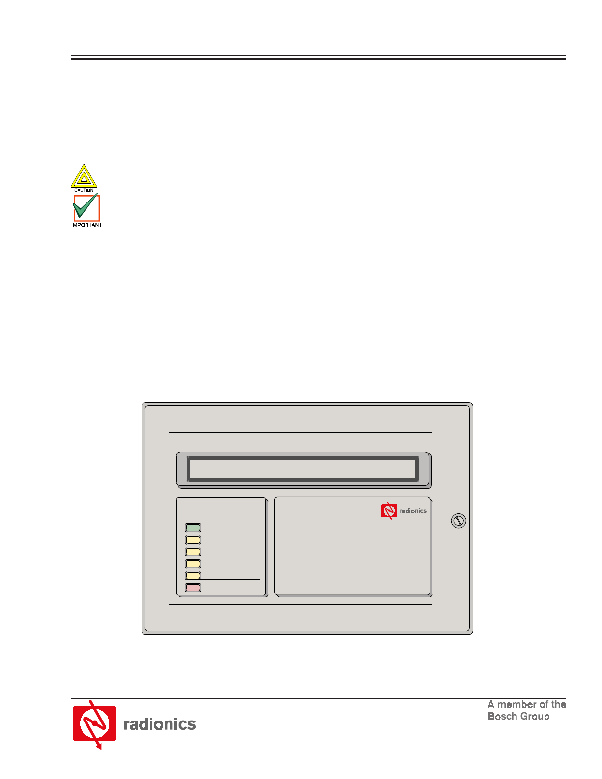
Six front panel display LEDs report system conditions. See Table 1 for a description of these LEDs. There are also four
on-board LEDs that indicate system activity. See Table 2 for a description of these LEDs.
An internal sounder signals the annunciator’s location in alarm conditions.
Each analog control panel can support up to 31 D9069A Fire System Annunciators.
Power
System Trouble
Trouble Silenced
Sounders Silenced
Point Bypassed
ALARM
Figure 1: D9069A Front Panel Display
Fire System Repeater
Page 2
een
)
minal Block
g
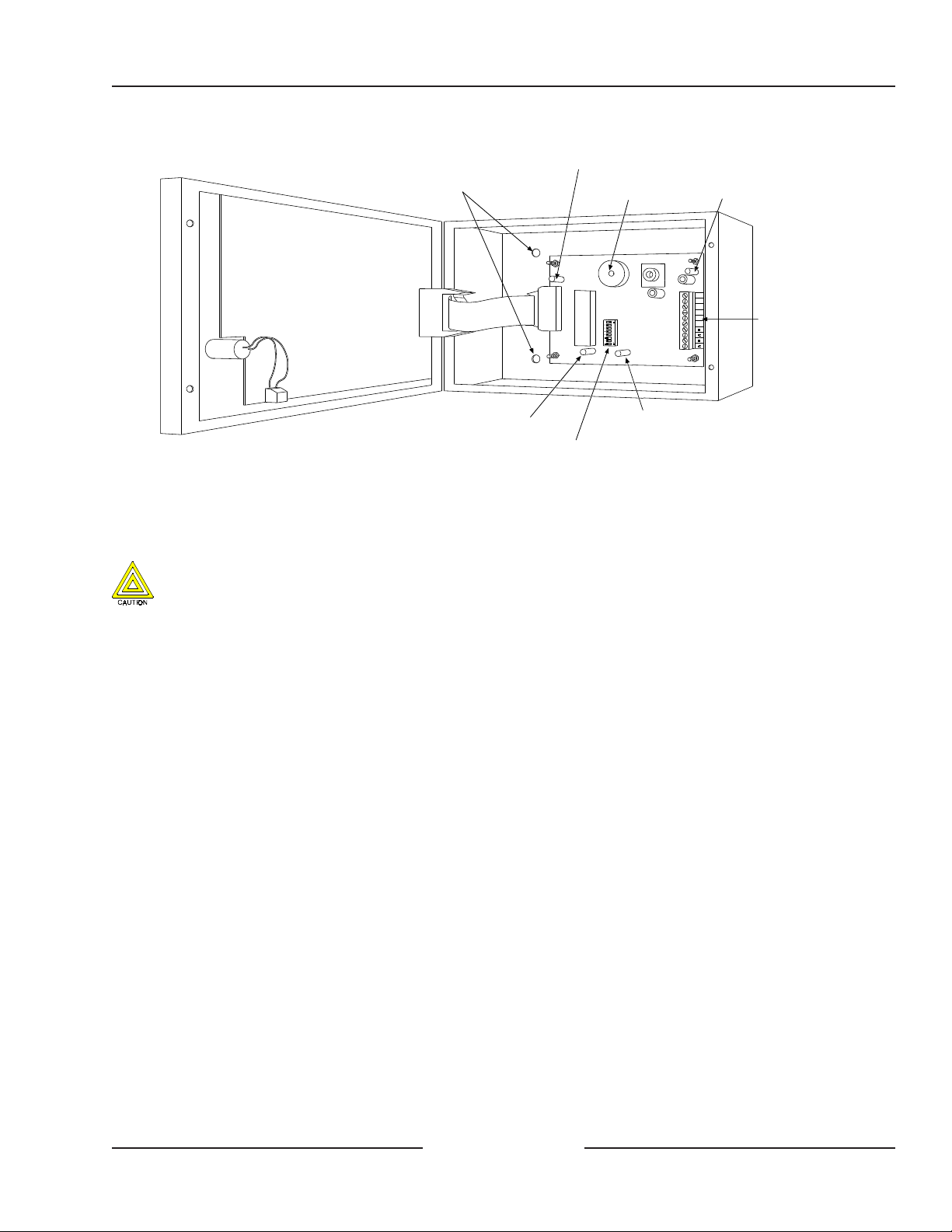
Mounting the D9069A
Holes for surface mountin
LED 2 (Green)
Sounder
+24V
+24V
OV
OV
EARTH
EARTH
D9069A
LED 1 (Gr
Te r
LED 3 (Yellow)
DIP switches
LED 4 (Red)
Figure 2: Internal View of D9069A
Note: Although the D9069A has a DIP switch block, it cannot be learned into a system. Leave all DIP switches in the OFF
(down) position.
3.0 Mounting the D9069A
Inform the operator before installing this device in an existing system. Remove all power (AC and battery) to
the FACP before installing this device. Failure to do so may result in personal injury and/or damage to the
equipment.
3.1 Semi-flush Mounting the D9069A
1) Prepare an opening in the wall 9 1/8 in. x 6 5/16 in. (23.2 cm x 16.0 cm)
2) Remove the knockouts from the D9069A as necessary for wiring conduit fittings.
3) Mount the D9069A enclosure in the wall.
4) Run the necessary wiring throughout the premises and pull the wires into the enclosure. Knockouts are provided
at the top and bottom of the enclosure.
5) Mount the D9081 Flush Mount Trim Ring to the enclosure.
3.2 Surface Mounting the D9069A
1) Remove the necessary knockouts and install conduit fittings.
2) Mount the enclosure in the desired location. Use all four mounting holes (see Figure 2 for mounting hole locations).
3) Run the necessary wiring throughout the premises and pull the wires into the enclosure. Knockouts are provided
at the top and bottom of the enclosure.
D9069A Installation Guide
Copyright © 2002 Radionics Page 2 50992B
Page 3

D9069A
1
LOO
P
D9067
Polling
Circuit
Modul
e
Wiring the D9069A
4.0 Wiring the D9069A
The D9069A terminal block connects to the D9051 RS-485 Bus Module on the FACP’s port reserved for peripheral
devices. See the
Figure 3 for wiring details.
1) Remove AC power from the system at the dedicated 120 VAC breaker and remove the standby battery power
before making or breaking any connections to the FACP.
2) The “A” and “B” wires must be connected to their respective terminals. Crossing the terminal connections (connecting
the “A” wire to the “B” terminal) will result in the FACP receiving corrupted data.
3) The last annunciator in a Class B (two-wire) circuit must have a 150 ohm, ¼ watt EOL resistor across the 485 OUT
“A” and “B” terminals.
4) The D9069A receives regulated 24 VDC power from a UL Listed FACP or a UL Listed for fire auxiliary power supply.
Connect the (+) 24 VDC wire to the (+) 24 V terminals. Connect the (-) 24 VDC wire to the 0 V terminal.
Note: Do not connect 24 VDC power to the “A” or “B” terminals. Doing so may result in personal injury and/or damage to
equipment.
5) Connect the earth ground wire to the EARTH terminal. If shielded wire is used, connect the drain wire to the EARTH
terminal.
Note: Unless shielded cable is properly grounded, it may aggravate rather than eliminate noise problems. Shielded cable
must be reconnected each time the cable is cut to install a device.
6) Restore power to the system by connecting the standby batteries and closing the 120 VAC dedicated breaker that
controls the power input to the FACP. The green AC Power LED on the panel display will light to show that the 120
VAC power supply is on and the standby power supply is connected.
D9051 Installation Guide
(P/N: 34048) or the FACP’s Installation Guide for port assignments. See
Common for Shielded Cable
D9069A Fire System Annunciator
or other peripheral device
+24 V
+24 V
0 V
0 V
EARTH
EARTH
B
A
B
A
EOL Resistor
D9069A Fire System Annunciator
+24 V
+24 V
0 V
0 V
EARTH
EARTH
B
A
B
A
24V.AUX.
0 V
E
+
-
+
-
OUT IN
BBAA
D9051
RS-485
Bus
+
LOOP
5
D10024 or D10024A
Control Module
Module
PL_LOOP4
PORT-C
AUX R ELAYS
RELAY 1
RELAY 2
N/O
N/C
COM N/C N/O
COM
(+) 24 VDC Aux Power
+
E-
-
+
+
-
E
+
LOOP
-
PL_LOO P3
PORT-B
SOUNDER
OUTPUTS
LOOP
4
E-
+
-
PL_LOOP2
LOO P
2
3
E-
+
-
+
Figure 3: D9069A to FACP Connections
Note: The wiring example shown in Figure 3 also applies to the D8024 Analog FACP.
Note: The D8024 and D10024 Series auxiliary power is limited to 340 mA. Each D9069A draws 125 mA at display.
D9069A Installation Guide
Copyright © 2002 Radionics Page 3 50992B
Page 4

5.0 D9069A LED Operation
There are two sets of LEDs on the D9069A Fire System Annunciator: the Front Panel Display LEDs and the System
Activity LEDs. The Front Panel Display LEDs are located on the outside of the D9069A’s enclosure door. See Figure 1.
The System Activity LEDs are located on the D9069A PCB. See Figure 2. See Tables 1 and 2 for the functions of these
LEDs.
DELlenaPtnorFDELlenaPtnorF
DELlenaPtnorFDELlenaPtnorF noitcnuFnoitcnuF
DELlenaPtnorF
rewoPtneserpsirewopCAelbatpeccatahtsetacidnI
elbuorTmetsyS rewop,gniriwCLS(metsysehtnitluafasierehttahtsetacidnI
decneliSelbuorT neebsahnoitidnoctlelbuorTfonoitaicnunnaehttahtsetacidnI
decneliSsrednuoS denrutyllaunamneebevahsecnailppanoitacifitontahtsetacidnI
dessapyBtnioP .delbasidyllaunamneebevahstupnieromroenotahtsetacidnI
MRALA naotnidehctalsahro,etatsmralanisitnioptupninasetacidnI
noitcnuFnoitcnuF
noitcnuF
dnadetcerrocneebsahtluafehtnehwsraelcsihT.).cte,tluaf
.teserneebsahlenapeht
elbuortehtnehwsraelcsihT.rotareponaybdecnelisyllaunam
ro,teserneebsahlenapehtdnadetcerrocneebsahnoitidnoc
.sruccoelbuortrehtona
ehtnehwsraelcsihT.etatsmralananillitssimetsysehttub,ffo
.tesersimetsys
.ecivresotdenruterera)s(tniopehtnehwsraelcsihT
.tesersimetsysehtnehwsraelcsihT.etatsmrala
1DELneerG.rewopCDgniviecersidraobehtetacidniotsthgiL
2DELneerG.PCAFehttaytivitcaUPCetacidniotsehsalF
3DELwolleY.PCAFmorfatadgniviecersidraobehtetacidniotsehsalF
4DELdeR.9609DnodesutoN
6.0 Specifications
Table 1: Front Panel Display LEDs
DELytivitcAmetsySDELytivitcAmetsyS
DELytivitcAmetsySDELytivitcAmetsyS roloCroloC
DELytivitcAmetsyS
roloCroloC noitcnuFnoitcnuF
roloC
Table 2: System Activity LEDs
noitacificepS9609DnoitacificepS9609D
noitacificepS9609DnoitacificepS9609D eulaVeulaV
noitacificepS9609D
egatloVgnitarepOCDV82ot02
egatloVylppuSlanimoNCDV42
warDtnerruCyalpsidtaAm521;evitcaniAm53
erutarepmeTgnitarepO)C05+otC0(F221+otF23+
ytidimuHevitaleR )C03,F68@(gnisnednocnon-HR%58ot5
noitcnuFnoitcnuF
noitcnuF
eulaVeulaV
eulaV
rotsiseRLOE051 Ω ttaw4/1,
© 2002 Radionics, a division of Detection Systems, Inc. 50992B 4/02
PO Box 80012, Salinas, CA 93912-0012 USA Installation Guide D9069A
Customer Service: (800) 538-5807 Page 4 of 4
 Loading...