

B36IT71SNS
B36IT71SN
INSTALLATION INSTRUCTIONS
INSTRUCTIONS D’INSTALLATION
INSTRUCCIONES DE INSTALACIÓN

INSTALLATION INSTRUCTIONS ............ 4
INSTRUCTIONS D’INSTALLATION.......... 23
INSTRUCCIONES DE INSTALACIÓN ...... 43
2

Content
Before you Begin ........................................................................................................................................ 4
General ......................................................................................................................................................... 4
Definitions ..................................................................................................................................................... 4
Important information .................................................................................................................................... 4
Installation options ..................................................................................................................................... 5
Individual unit ................................................................................................................................................ 5
Individual appliances with partition ................................................................................................................ 5
At the end of the kitchen units ....................................................................................................................... 5
Installation location ..................................................................................................................................... 6
Installation room ............................................................................................................................................ 6
Installation cavity ........................................................................................................................................... 6
Furniture/fixtures ........................................................................................................................................... 6
Base ............................................................................................................................................................. 6
Connecting the power ................................................................................................................................ 7
Connecting the water ................................................................................................................................. 7
Installation dimensions ............................................................................................................................... 8
Appliance dimensions ................................................................................................................................ 9
Required accessories and tools ................................................................................................................ 10
Supplied accessories .................................................................................................................................... 10
Optional accessories ..................................................................................................................................... 10
Other required accessories from specialist outlets ......................................................................................... 10
Tools ............................................................................................................................................................. 10
Other ............................................................................................................................................................ 10
Installation instructions .............................................................................................................................. 11
1. Checking the installation cavity .............................................................................................................. 11
2. Transport of the appliance ..................................................................................................................... 11
3. Removing the packaging ....................................................................................................................... 12
4. Installation preparation ........................................................................................................................... 13
5. Preparing the installation cavity .............................................................................................................. 13
6. Attaching an alternative anti-tip device ................................................................................................... 14
7. Preparing to connect the water ............................................................................................................. 15
8. Attaching the edge protection ............................................................................................................... 15
9. Pushing the appliance into the installation cavity .................................................................................... 16
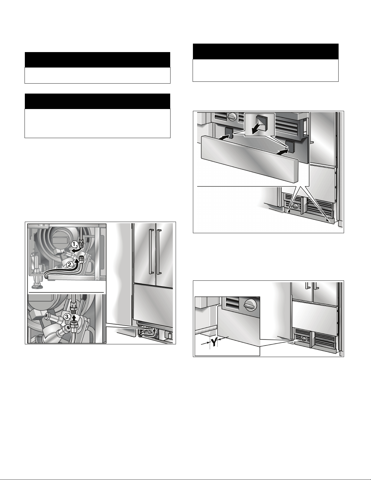
10. Removing stainless steel front panel from the freezer compartment drawer ........................................... 17
11. Aligning the appliance ............................................................................................................................ 17
12. Attaching the appliance in the cavity ...................................................................................................... 18
13. Connecting the water to the appliance .................................................................................................. 19
14. Attaching the toe kick panel .................................................................................................................. 19
15. Attaching stainless steel front panel to the freezer compartment drawer ................................................ 20
16. Commissioning the appliance ................................................................................................................ 21
17. Attaching the covers .............................................................................................................................. 21
18. Adjusting the door opening angle (refrigerator compartment door) ......................................................... 21
19. Changing the door spring ...................................................................................................................... 22
3

Before you Begin
Read these instructions completely and carefully.
m WARNING
These appliances are top-heavy and must be secured to
prevent the possibility of tipping forward. Anti-tip protection
is required.
Keep doors closed until the appliance is completely installed
and secured per installation instructions.
Due to the weight and size of this appliance, and to reduce
the risk of personal injury or damage to the product –
TWO PEOPLE ARE REQUIRED FOR PROPER
INSTALLATION.
This appliance must be properly grounded. See the section
on “Connecting the power”.
Use this appliance only for its intended purpose.
Immediately repair or replace electric service cords that
become frayed or damaged.
Unplug the appliance or switch off the fuse before cleaning
or making repairs.
Repairs should be made by a qualified service technician.
m CAUTION
Skill - Level - Installation of this appliance requires basic
mechanical, carpentry and plumbing skills.
Proper installation is the responsibility of the installer.
Product failure due to improper installation is not covered
under the Appliance Warranty.
See the Owner's Manual for warranty information.
m IMPORTANT
Save these instructions for local inspector's use. Observe all
governing codes and ordinances.
Note to Installer - Be sure to leave these instructions with
the Consumer.
Note to Consumer - Keep these instructions with your
Owner's Manual for future reference.
General
These installation instructions are intended for use by
qualified installers. All connections for water, electrical power
and grounding must comply with local codes and ordinances
and be made by licensed personnel when required.
In the absence of a local code:
– In the U.S.A., in accordance with the National Electric
Code, ANSI/NFPA70 - latest edition/State and
Municipal codes and/or local codes.
– In Canada, in accordance with the Canadian Electric
Code C22.1 - latest edition/Provincial and Municipal
codes and/or local codes.
Definitions
m
WARNING – This indicates that death or serious
injuries may occur as a result of not observing this
warning.
m
CAUTION – This indicates that minor or moderate
injuries or damage may occur as a result of not
observing this warning.
WARNING
CAUTION
m
m
NOTE
IMPORTANT NOTE / NOTE – This is used to draw
the user's attention to something in particular.
Important information
The importance of complying with all regulations and
instructions in this installation manual cannot be emphasised
enough. The installation should be carried out by a qualified
fitter.
Before starting the installation, always read this installation
manual in full. It contains important details which the fitter
must observe. Provided this manual is read thoroughly,
the installation will be simple, trouble-free and,
most importantly, safe.
4
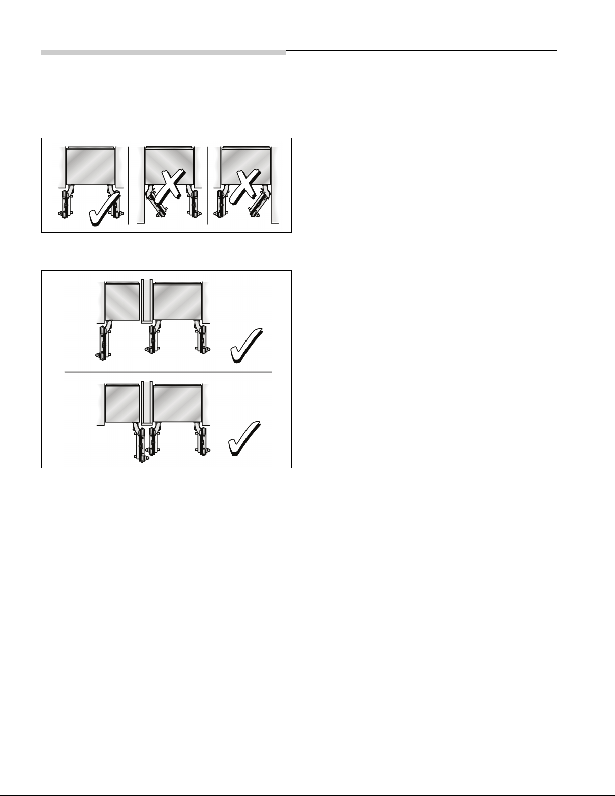
Installation options
1.
2.
The different installation options are limited only by the design
of the kitchen and the function of the finger guard.
Individual unit
Individual appliances with partition
At the end of the kitchen units
If one side of the appliance is visible, a side panel must be
used.
The side panel must be connected firmly to the wall, the floor
and overhead furniture/fixtures before the appliance is placed
in the cavity.
The dimensions of the side panel are taken from the opposite
cavity wall. During installation ensure that the cavity is square
and the exact size.
– When dimensioning the partition for model 2, note the
thickness of the furniture fronts to prevent damage if the
doors are opened at the same time.
– Use the Extreme Combination Side-by-Side Heating kit
if the gap between the appliances is less than 6"
(160 mm).
See the section on “Optional accessories”.
– Minimum thickness of the partition
5
/8" (16 mm).
5

Installation location
m
Do not install the appliance:
–outdoors,
– in an environment with dripping water,
– in rooms which are at risk of frost.
Appliance is very heavy – for empty weight see the
following table:
BM (Bottom Mount) 36" approx. 430 Ibs / 195 kg
WARNING
m
Installation room
The appliance should be installed in a dry, ventilated room.
The ambient temperature should not drop below
55 °F (13 °C) or rise above 110 °F (43 °C), otherwise
malfunctions may occur.
The installation location should not be exposed to direct
sunlight and not placed near a heat source, such as an oven,
radiator, etc. If installation next to a heat source is
unavoidable, use a suitable insulating plate or observe the
following minimum distances from the heat source:
1
/4" (30 mm) from an electric cooker,
–1
– 12" (300 mm) from an oil or solid-fuel cooker.
Furniture/fixtures
The new appliance is screwed securely to adjacent and
overhead furniture/fixtures.
For this reason it is essential that all attachable furniture/
fixtures are connected securely to the base or the wall by
suitable means.
Base
m
A fully-load appliance is very heavy – for the loadbearing capacity at least see the following table:
BM (Bottom Mount) 36" approx. 1200 Ibs / 540 kg
To ensure that the appliance is installed securely and
functions properly, the base must be flat and level.
The base must be made of a hard, rigid material.
The installation area must be the same height as the rest of
the room.
On account of the heavy weight of a fully loaded appliance,
a load-bearing base is required. If in doubt, contact an
architect or a building expert.
WARNING
m
Installation cavity
It is important to observe the specified dimensions of the
installation cavity for a trouble-free installation of the
appliance and for the subsequent general view of the
furniture front.
In particular ensure that the cavity is square.
Squareness can be checked by suitable means, e.g. spirit
level, diagonal measurements, etc..
The side walls of the cavity must be flush.
The minimum thickness of side walls and the top wall must
5
/8" (16 mm).
be
The minimum thickness of toe kick panel must
1
/2" (13 mm).
be
3
A thickness of
/4" (19 mm) is recommended.
6

Connecting the power
Connecting the water
m
Electrical Shock Hazard
– Plug into a grounded 3 prong outlet.
– Do not remove ground prong.
– Do not use an adapter.
– Do not use an extension cord.
Failure to follow these instructions can result in death,
fire, or electrical shock.
The appliance comes with a 3-wire power supply cord,
UL listed in the USA.
The appliance requires a 3-wire receptacle.
The receptacle must be installed by a licensed electrician
only.
The socket must be fused with a 10 to 16 A fuse.
Please observe in this coherence the following table:
Appliance Maximum load at one time
Bottom Freezer 36“ 6.0 Ampere
Orient ground prong to the bottom as shown in the pictures.
For the installation position of the receptacle see “Installation
dimensions”.
WARNING
m
m
Only connect the appliance to drinking water!
A cold water connection is required for operation of the
automatic ice maker. The water pressure must be between
25 and 120 p.s.i. (1.72–8.25 bar). The installation must
comply with local plumbing regulations.
A separate shut-off valve must be installed for the appliance
water connection.
The shut-off valve for the water connection must not be
behind the appliance. It is recommended to place the shutoff valve directly next to the appliance (base unit) or in another
easily accessible location.
When installing the water connection, observe the permitted
installation areas for the pipe. For the permitted installation
areas and dimensions see “Installation dimensions”.
The supply pipe can be located at the side on the right (a), at the
side on the left (b) or underneath (c).
Maximum outer diameter of
the water pipe (without fittings):
Attach a separate shut-off valve for the water connection in
asuitable, easily accessible location.
Do not use a self-piercing valve!
CAUTION
13
/32" (10 mm).
m
Additional grounding procedure
Some local regulations may require a separate ground. In
such cases, the required accessory ground wire, clamp and
screw must be purchased separately.
Never ground the appliance to plastic plumbing lines, gas
lines or water pipes.
Grounding instruction
This appliance must be grounded. In the event of
a malfunction or breakdown, grounding will reduce the risk of
electric shock by providing a path of least resistance for the
electric current.
m
Improper connection of the equipment grounding
conductor may result in electric shock. Have the
appliance checked by a qualified electrician or service
technician if you are in doubt as to whether the
appliance has been properly grounded.
WARNING
m
7
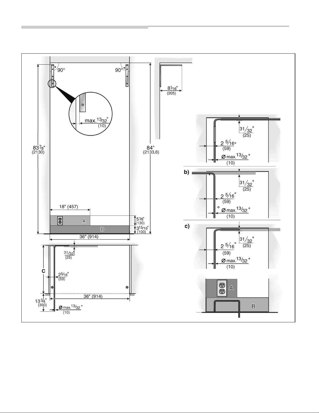
Installation dimensions
Single installation
Legend:
A Area for installation of the power connection
B Area for installation of the water connection
D Opening depth of niche, depending on kitchen design
D = 24" (610 mm) minimum
8
NOTE: Cavity must be suare.
Side wall of the cavity must be flush
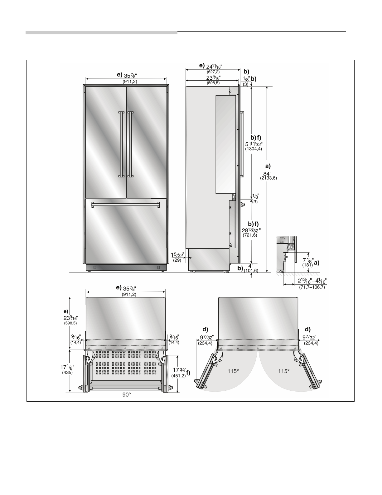
Appliance dimensions
Legend:
a) Adjustment in levelling legs +1
b) Dimensions may vary.
d) This dimension may vary depending on installation, panel
thickness and kitchen hardware.
3
/8" (35 mm) / –1/2" (13 mm).
e) Unit dimensions
f) Wooden door panel dimensions
9

Required accessories and tools
Supplied accessories
– Installation instructions
– Operating instructions
– Installation kit
Optional accessories
Extreme Combination Side-by-Side Heating kit
If the gap between the appliances is less than 6" (160 mm).
Other required accessories from
specialist outlets
Ice maker installation kit 1/4" OD copper line
For connecting appliances which require water, e.g. for an
ice maker.
Maximum outer diameter of the water pipe
(without fittings):
13
/32" (10 mm).
Too ls
– Cordless screwdriver T20
– Torx screwdriver T20
– Torx bit T20 + magnetic holder
5
–
/16" (8 mm) hex nut driver
– Wood drills in different sizes
1
– Open end wrench
–Multigrip pliers
– Adjustable wrench
– Cutter with adjustable blade
– Metal tape measure
–Square
– Spirit level length 2' (60 cm) and 4' (1,2 m)
– Marking-out level, length at least 4' (1.2 m) for individual
appliances or 7' (2.0 m) for Side-by-Side installation
/2" (SW 13 mm)
Other
– Stepladder
– Dolly, hand truck
– Hammer drill for drilling holes in wall or floor
– Bits according suitable for material and in different sizes
– Wooden beam (cross section min. 3" x 4"
(75 x 100 mm²) as an alternative tilt protection,
length according to the width of the installation cavity
– Wooden screws in different sizes
–Thin (max.
the floor from damage (e.g. lino)
– Suitable material for covering and protecting furniture
(e.g. protective sheets)
– Adhesive tape
1
/16" (1.5 mm)), suitable material to protect
NOTE
Before using, check whether the removed adhesive
tape leaves adhesive residue on the work surfaces!
Otherwise do not use on high-quality work surfaces.
10
Installation instructions
1. Checking the installation cavity
m
To ensure a safe, trouble-free installation and an
optimum overall view of the subsequent furniture front,
thoroughly check that the installation cavity complies
with the installation requirements.
Before starting the installation, check that the installation
cavity complies with all requirements for a safe and troublefree installation.
Check the base.
Follow the instructions in the section on “Installation
location”.
Check the dimensions of the cavity.
Check that the cavity is square.
Check location of the socket.
Also follow the instructions in the section on
“Connecting the power” and in the section on
“Installation dimensions”.
Check location of the water connection (only for
appliances with ice maker).
Also follow the instructions in the section on
“Connecting the water”.
Check attachment of the adjacent furniture/fixtures.
All furniture parts in the vicinity of the appliance must
be connected securely to the wall.
Check that adjacent furniture/fixtures do not collide
(door opening angle).”
CAUTION
m
2. Transport of the appliance
m
The appliance is very heavy. Be careful, otherwise
people who are helping may be injured or the
appliance may be damaged.
Transport the appliance to a suitable installation location
with suitable means of transportation (trolley, lifting truck
or hand-driven truck).
Secure the appliance during transportation to prevent it
from overturning.
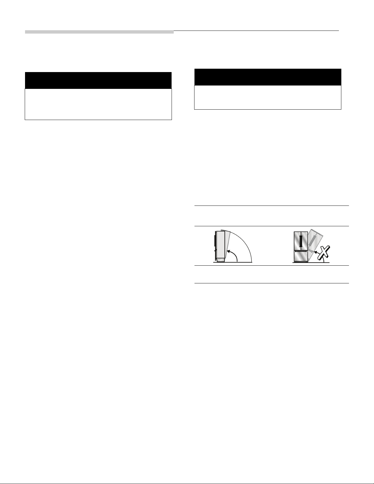
The appliance is 84“ (2134 mm) tall. If the appliance cannot
be transported in an upright position due to the structural
conditions, the appliance can be transported horizontally.
When erecting the appliance, observe the required minimum
height at the installation location according to the following
table:
Erection via appliance rear Erection via appliance
86“ / 2185 mm
CAUTION
side panel
Never put the appliance
up via its side!
m
11
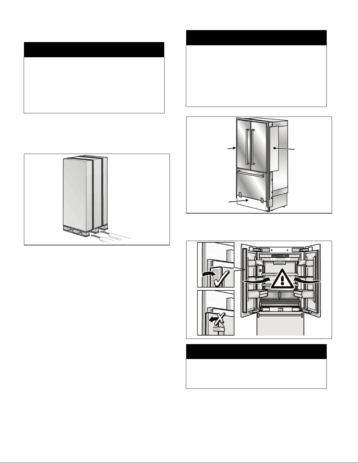
3. Removing the packaging
A
B
B
m
CAUTION
m
m
– The appliance may tip over while it is being
unpacked.
– The appliance is very heavy.
– When opening the appliance door, the appliance
may tip forwards.
Be careful, otherwise people who are helping may be
injured or the appliance may be damaged.
To protect the base from damage during installation:
Attach a residual piece of carpet, lino, etc. to the floor
with adhesive tape in front of the intended installation
location.
WARNING
m
Do not remove transportation protection device (A)
from the underside of the freezer compartment drawer.
Do not damage finger guard (B) while performing the
following steps.
Do not remove transportation safety devices which
protect the shelves and storage compartments inside
the appliance until the installation is complete,
otherwise the parts may be damaged.
Move the appliance with a hand truck securely.
Remove transportation packaging:
– Using adhesive tape, attach the power cord to the
back of the appliance.
– Remove transportation protection devices and lift
appliance off the pallet – appliance is very heavy!
– Remove accessories from the outside of the
appliance.
– Keep adhesive tape which was used to attach the
supplied accessories to the appliance.
It is used subsequently for attaching the edge
protection to the cavity walls (see Section 8.).
– Carefully open the appliance – risk of tipping over –
and remove accessories and installation materials
from inside the appliance. Close doors again!
Check appliance for damage in transit.
Do not install the appliance if it is visibly damaged. If in
doubt, contact your dealer.
m
Care should be taken when closing the door. The
folding rail attached to the door of the refrigerator
compartment has to be folded if the door are closed.
Risk of damage!
CAUTION
m
12
4. Installation preparation
Unpack installation materials and accessories.
To improve allocation to the work steps, the packages are
identified differently.
To do this, comply with the overview sheet attached to the
appliance!
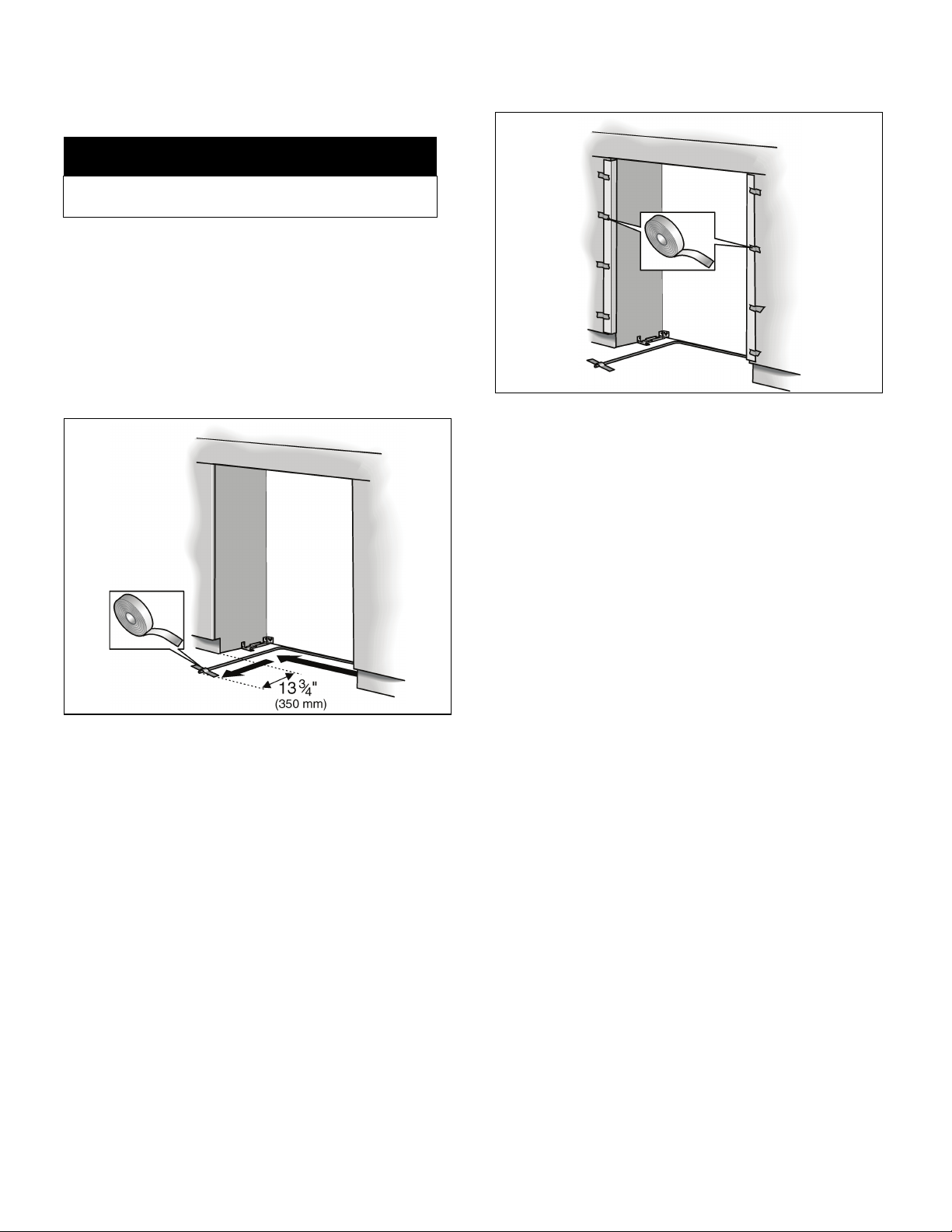
5. Preparing the installation cavity
The length of the plank should correspond to the width of the
installation niche!
Specify the attachment points of the anti-tip-angles.
Specify the detailed dimensions according to the section
on “Installation dimensions”.
Attach the anti-tip-angles completely. Be sure screws
hold tight.
Fastening with wood screws
m
Assure that there are no electrical wires or plumbing in
the area which the screws could penetrate.
Risk of injury and damage!
WARNING
m
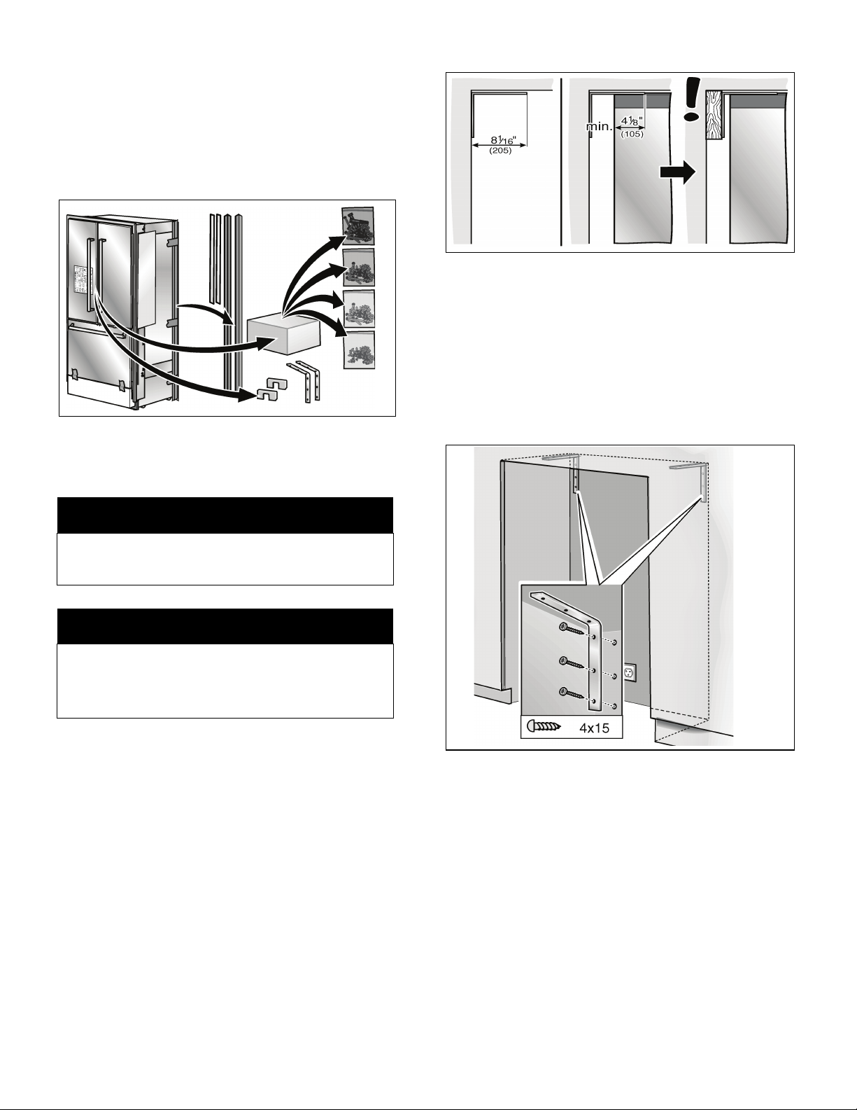
NOTE
– 2 anti-tip-angles are required for each appliance.
– The supplied set contains fastening screws for
various applications. Select the fastening screws
according to the local conditions.
The anti-tip-angles must have a minimum length of 41/8”
(105 mm) over the appliance to ensure a secure stand of the
appliance.
If this minimum length cannot be observed for structural
conditions it is possible to do this by fastening a spacer
behind the anti-tip angle, e. g. a sufficiently dimensioned
wood plank.
13
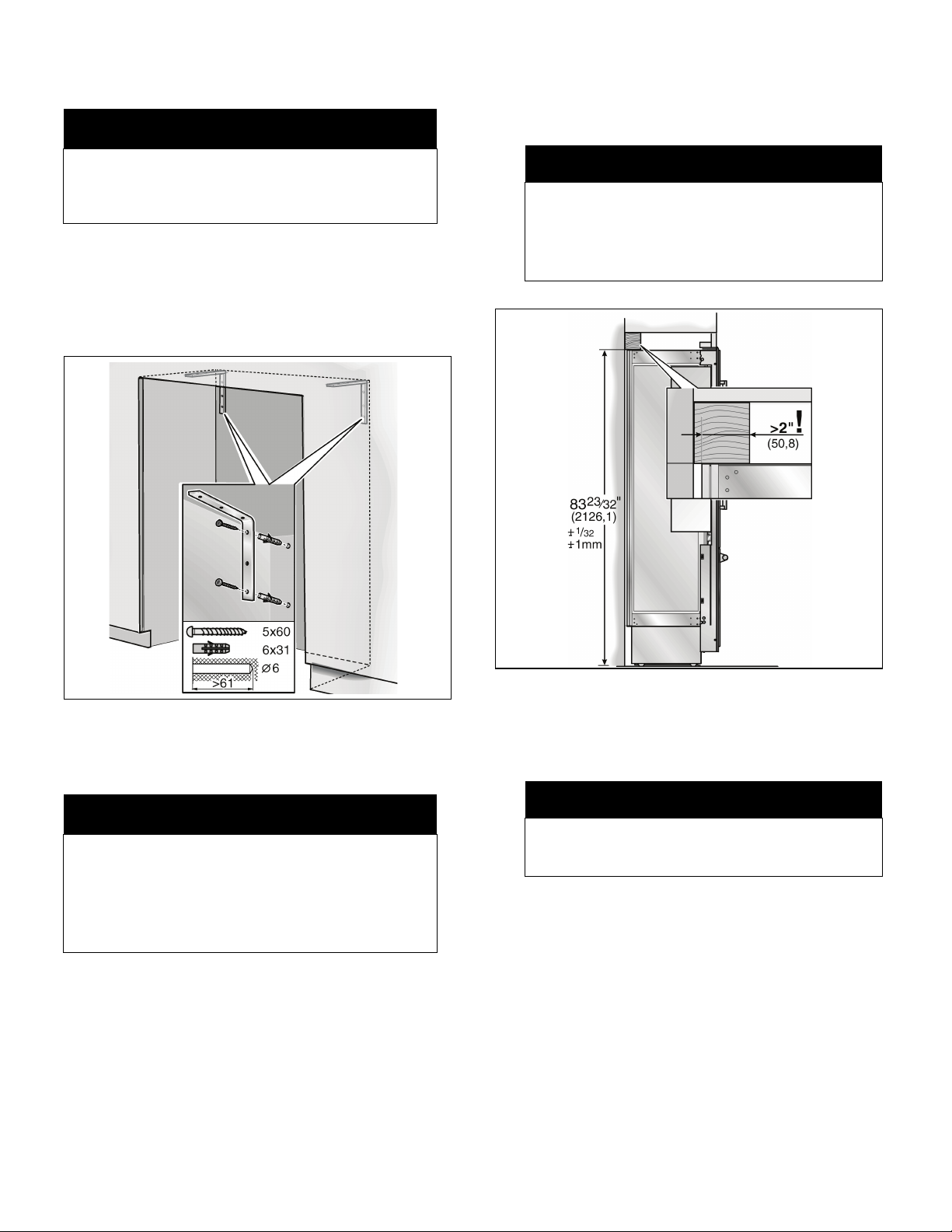
Fastening with dowels and screws
m
CAUTION
m
Saw the wooden beam (cross section min. 3" x 4")
to the required length.
Length is equal to the width of the installation cavity!
Always wear safety glasses and other necessary protective devices or apparel when installing or working
with anchors.
Risk of injury!
Not recommended for use in light-weight masonry material
such as block or brick.
Not recommended for use in new concrete which has not
had time to cure.
Do not use core drills to drill holes for this anchor.
NOTE
– If the installation cavity is deeper than the
appliance, select a beam which has a larger cross
section or attach 2 beams.
– The beam must cover the appliance by
at least 2" (50.8 mm).
6. Attaching an alternative anti-tip
device
IMPORTANT NOTE
If the anti-tip brackets cannot be attached securely,
an alternative anti-tip device can be attached.
However, ensure that there is no play between the
appliance and the anti-tip device.
If possible, always screw the wooden beam to existing
studs on the rear panel of the cavity.
Mark the installation height (lower edge of the beam) on
the rear panel of the cavity.
Select screws according to the thickness of the wooden
beam: length = min. 2.5 x beam thickness, diameter #12
or #14.
NOTE
Specify the number of screws according to the cavity
width, thereby ensuring that the beam can be
attached securely.
According to the subsurface:
Locate wall studs near the rear panel of the cavity and
mark drill holes in the beam
or
Fasten suitable dowel into the rear wall.
Predrill the wooden beam.
Attach the wooden beam to the rear panel of the cavity.
14
7. Preparing to connect the water
(only for appliances which require a water connection)
8. Attaching the edge protection
m
Turn off the main water tap to prevent damage caused
by leaking water.
Attach the connecting pipe to the shut-off valve
according to the instructions supplied by the
manufacturer of the ice maker installation kit.
Install the connecting pipe.
Always observe the indicated gap dimensions to prevent
damage to the connecting pipe when pushing in the
appliance.
CAUTION
m
To protect the corners of the installation cavity, attach
the supplied protective brackets with adhesive tape.
Attach the connecting pipe to the floor with adhesive
tape.
15
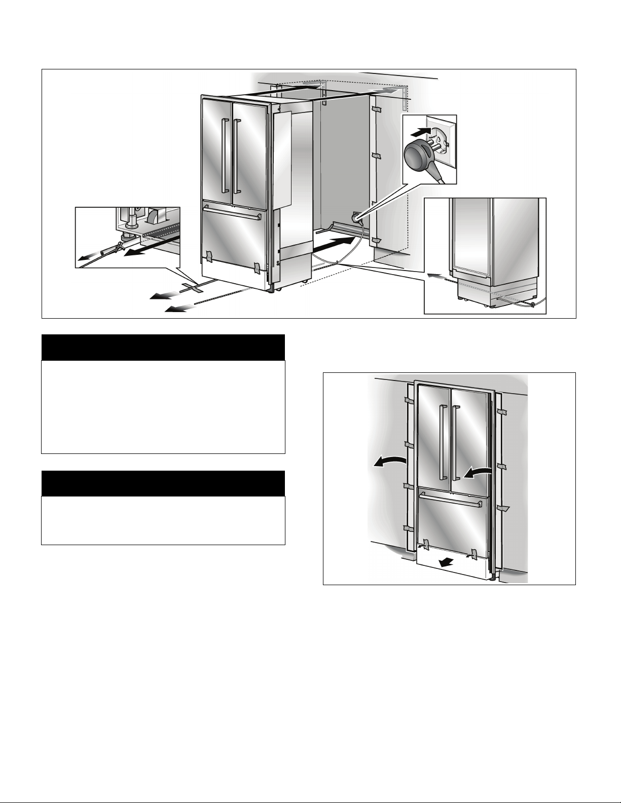
9. Pushing the appliance into the installation cavity
Carefully push the appliance into the cavity. Insert
m
Caution when pushing the appliance into the installation
cavity.
– Do not damage the water pipe or power cord
attached to the floor.
– Check finger guard on both sides when pushing the
appliance into the cavity. Immediately after pushing
the appliance into the cavity, check that it functions
by opening and closing the doors.
CAUTION
m
appliance straight! Push in the appliance until the frame
is situated on the cavity walls.
NOTE
When the floor or the appliance is tilted in comparison
to the installation cavity adjust height adjustable wheels
before you move the appliance into the installation
cavity.
Put the mains plug into the socket.
Prevent the power cord from becoming caught.
Tie a piece of string to the middle of the power cord and
feed forwards under the appliance. When pushing in the
appliance, pull the cable forwards.
or
Using adhesive tape, stick the power cord to the floor
centrally behind the appliance approx. 15" (380 mm)
away from the rear panel of the cavity.
16
Remove the edge protection.
Remove transportation protection device from the
underside of the freezer compartment drawer.
Check function of the finger guard.
Open and close both doors of the refrigerator
compartment. The finger guard must slide smoothly in
the gap between the appliance and cavity wall.
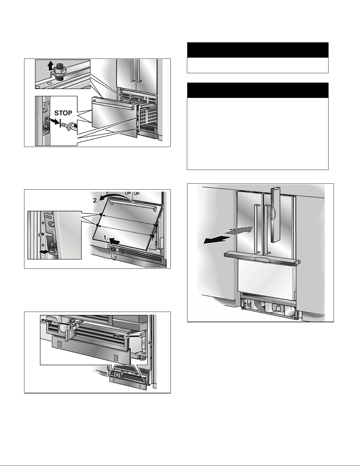
10. Removing stainless steel front panel
from the freezer compartment
drawer
Loosen and unscrew nuts on the top of the door.
However, do not turn the threaded bolts, otherwise
the door will no longer be aligned.
Do not loosen the screws on the left and right fixing
brackets. Do not unscrew the screws!
11. Aligning the appliance
m
Never use a cordless screwdriver!
Risk of damage to the appliance.
CAUTION
NOTE
– Do not twist or jam the appliance inside the cavity!
When unscrewing the height-adjustable feet,
proceed gradually: Always alternate between left
and right, left and right, etc..
– The adjustment of the rear feet is facilitated if the
appliance is unloaded at the rear.
– If using a wooden beam as an alternative anti-tip
device according to point 6 of this installation
manual, rotate the appliance all the way towards the
wooden beam.
m
Pull the bottom of the stainless steel front panel away
from the door to remove the fixing brackets from the
screws. Then lift the door off the threaded bolts.
Place fixing brackets only loosely into the plates.
Ensure that you do not lose them.
Remove base panel from the appliance.
Align the appliance with the furniture fronts.
The height-adjustable feet at the front and rear can all be
adjusted from the front.
Front: with open-ended wrench
5
Rear: with
A mark is attached to the appliance base and is used as a
standard gage for height adjustment. When adjusting the
height, align this mark at a height of 1
floor.
/16" (8 mm) hex nut driver via flexible shaft.
1
/2" (SW13)
1
/4" (32 mm) above the
17
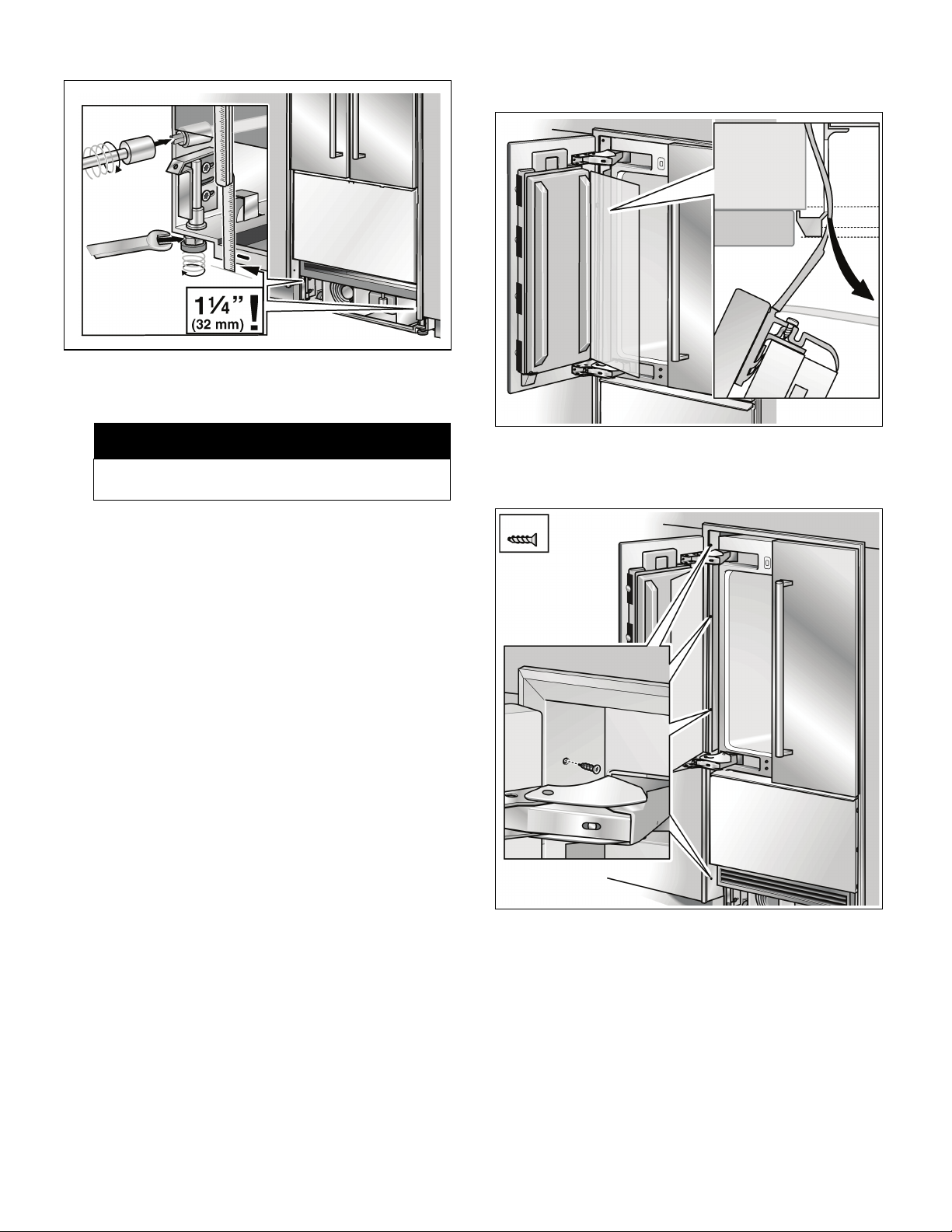
Unscrew the height-adjustable feet until the mark on
the base has reached the indicated guide dimension
1
/4" / 32 mm).
(1
12. Attaching the appliance in the cavity
NOTE
It is very important to comply with this dimension for
the subsequent alignment of the furniture fronts.
Align the furniture fronts with the spirit level.
Before attaching the appliance in the cavity, check
– that the top and sides of the frame are situated on
the cavity front,
– that the finger guard functions by opening and
closing the two refrigerator compartment doors
several times.
Open one door of the refrigerator compartment.
Pull finger guard all the way out of the gap between the
appliance and cavity wall.
18
Screw the frame to the cavity wall through the gap
between the door and carcass (3 screws).
Under the freezer compartment drawer screw the frame
to the cavity wall (1 screw).
Open the other door of the refrigerator compartment
and pull out the finger guard. Screw frame to the cavity
wall (4 screws).
Push the finger guard through the frame recess into the
gap between the appliance and cavity wall
13. Connecting the water to the
appliance
m
When bending the water pipe, do not kink it, otherwise
there is a risk of leaks and water damage.
CAUTION
m
NOTE
When connecting the water pipe to the solenoid valve
of the appliance, follow the instructions supplied by the
manufacturer of the ice maker installation kit enclosed
with the installation manual.
Remove the cap from the appliance connection (1.).
Bend the water pipe according to the location of the
connection on the appliance (2.).
Push the union nut and seal onto the water pipe.
Push the end of the water pipe into the appliance
connection and screw on the union nut (3.).
Tighten hand-tight.
Using the open-ended wrench, tighten the union nut.
Do not overturn!
14. Attaching the toe kick panel
m
The maximum height of the toe kick panel is 4" from the
top of the floor. Do not cover ventilation slots in the base
panel. Risk of damage to the appliance.
If required, cut the toe kick panel to the required length.
Attach the base panel to the appliance.
CAUTION
m
Open the shut-off valve and main water tap. Check the
connection on the shut-off valve and on the appliance
for leaks.
Remove the protective film from the adhesive pads on
the Velcro.
Fit the toe kick panel to the base panel and press firmly
into place.
Remove base panel from the appliance.
Put on the base panel (do not screw on) and measure
the difference in depth Y between the base panel and
toe kick panel of the adjacent furniture.
Remove the base panel.
Loosen the brackets for attaching the base panel and
push in all the way.
19
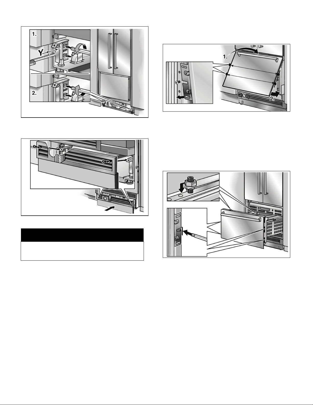
Pull out the brackets by the measured amount Y.
Screw the brackets tightly.
15. Attaching stainless steel front panel
to the freezer compartment drawer
Hang stainless steel front panel over the threaded bolts.
Lift bottom of stainless steel front panel and push the
fixing brackets down over the screws.
When the freezer compartment door is closed, check
the depth of the stainless steel front panel with respect
to the adjacent furniture front panels.
If the depth alignment is correct, tighten the screws on
the fixing brackets.
Attach the base panel.
NOTE
If required, the toe kick panel can be screwed to the
base panel. There are screw holes in the base panel
near the Velcro.
Screw nuts onto the threaded bolts on top of the door.
Do not tighten yet.
Check lateral alignment of the stainless steel front panel.
If the lateral alignment is correct, tighten the nuts.
20

16. Commissioning the appliance
m
Check that the finger guard functions. In particular check
– that the finger guard is correctly attached to the
appliance and
– that the finger guard slides smoothly forwards and
backwards when the refrigerator compartment
doors open and close.
To guarantee the accuracy of the following working steps
and thus the appearance of the overall kitchen front later on,
the appliance should now be operated.
Open the appliance door.
Press the POWER button.
Only for appliances with a water connection:
CAUTION
m
NOTE
In order to avoid the risk of damage caused by leaking
water from damage possibly caused to the water pipe
feeding the appliance, keep the shut-off valve closed.
17. Attaching the covers
Insert the cover plate on the freezer compartment door.
18. Adjusting the door opening angle
(refrigerator compartment door)
Depending on the installation situation, it may be necessary
to adjust the door opening angle. A door opening angle of
115° has been set at the factory.
To adjust the door opening angle to 90°:
Open the door to 90°.
Press cover strips on the handle sides of the doors into
the gap between stainless steel front and appliance
door.
Press cover strips on the freezer compartment drawer
into the gap between stainless steel front and drawer.
Insert the banking pin through the boreholes which are
now vertically aligned and drive in with a hammer.
21

19. Changing the door spring
To adjust the door spring:
Rotate the adjusting screw with a cross-head
screwdriver.
I = maximum spring tension
0 = no spring tension
22

Table de matières
Avant de commencer ................................................................................................................................. 24
Générale ....................................................................................................................................................... 24
Information importante .................................................................................................................................. 24
Options d'installation .................................................................................................................................. 25
Unité individuelle ........................................................................................................................................... 25
Appareils individuels avec séparation ............................................................................................................ 25
A l'extrémité des cuisines intégrées ............................................................................................................... 25
Lieu d'installation ........................................................................................................................................ 26
Local d'installation ........................................................................................................................................ 26
Cavité d'installation ....................................................................................................................................... 26
Meubles/Appareillages électriques ................................................................................................................ 26
Sol ................................................................................................................................................................ 26
Raccordement à l'alimentation électrique ................................................................................................. 27
Procédure additionnelle de mise à la terre ..................................................................................................... 27
Instructions de raccordement à la terre ......................................................................................................... 27
Raccordement de l'eau .............................................................................................................................. 27
Dimensions d'installation ........................................................................................................................... 28
Dimensions de l'appareil ............................................................................................................................ 29
Accessoires et outillage requis .................................................................................................................. 30
Accessoires fournis ....................................................................................................................................... 30
Accessoires en option ................................................................................................................................... 30
Autres accessoires requis de fournisseurs spécialisés ................................................................................... 30
Outils ............................................................................................................................................................ 30
Autres ........................................................................................................................................................... 30
Instructions d'installation ........................................................................................................................... 31
1. Vérification de la cavité d'installation ...................................................................................................... 31
2. Transport de l'appareil ........................................................................................................................... 31
3. Enlèvement de l'emballage .................................................................................................................... 32
4. Préparation du montage ........................................................................................................................ 33
5. Préparation de la cavité d'installation ..................................................................................................... 33
6. Fixation d'un dispositif anti-renversement alternatif ................................................................................ 34
7. Préparation du raccordement de l'eau ................................................................................................... 35
8. Fixation du protège-bordures ................................................................................................................ 35
9. Pousser l'appareil dans la cavité d'installation ........................................................................................ 36
10. Retirer la façade en acier inoxydable du tiroir du compartiment congélateur .......................................... 37
11. Installation et alignement de l'appareil .................................................................................................... 37
12. Fixer l'appareil dans la cavité ................................................................................................................. 38
13. Raccordement de l'eau à l'appareil ........................................................................................................ 39
14. Fixation du bandeau de socle ................................................................................................................ 39
15. Montage de la façade en acier inoxydable contre le tiroir du compartiment congélateur ........................ 40
16. Mise en service de l'appareil .................................................................................................................. 41
17. Fixation des couvercles ......................................................................................................................... 41
18. Ajustage de l'angle d'ouverture de porte ............................................................................................... 42
19. Changement du ressort de porte .............................................................................................
.............. 42
23

Avant de commencer
Veuillez lire ces instructions entièrement et avec attention.
m AVERTISSEMENT
Le centre de gravité de cet appareil se trouve assez haut
dans celui-ci. Il faut donc sécuriser l'appareil pour l'empêcher
de basculer en avant. Un protection anti-renversement est
nécessaire.
Maintenez les portes de l'appareil fermées jusqu'à ce qu'il ait
été installé et sécurisé conformément aux instructions
d'installation.
Vu le poids et la taille de l'appareil et pour réduire le risque de
dommages corporels et d'endommagement du produit,
IL FAUT DEUX PERSONNES POUR RÉALISER
L'INSTALLATION CORRECTEMENT.
Cet appareil doit être correctement relié à la terre.
Voir la section «Raccordement à l'alimentation électrique ».
Veuillez n'utiliser cet appareil qu'aux fins pour lesquelles
il a été prévu.
Réparez ou remplacez immédiatement les cordons
d'alimentation électrique qui se sont usés ou sont
endommagés.
Débranchez l'appareil ou ramenez le disjoncteur en position
éteinte avant de nettoyer ou d'effectuer des réparations.
Les réparations sont réservées à un technicien qualifié du
service après-vente.
m ATTENTION
Générale
Les présentes instructions d'installation sont destinées à être
utilisées par des installateurs qualifiés. Tous les
raccordements de l'eau, de l'électricité et à la terre doivent se
conformer aux règlement et ordonnances locaux, ils doivent
être réalisés par du personnel sous licence lorsque
nécessaire. En l'absence de réglementation locale :
– Aux USA : en conformité avec le National Electric Code,
ANSI/NFPA70 en son édition la plus récente, avec les
règlements des États et municipaux et/ou les
règlements locaux.
– Au Canada : en conformité avec le Code canadien de
l'électricité C22.1 en son édition la plus récente, avec les
règlements des provinces et municipaux et/ou les
règlements locaux.
m
AVERTISSEMENT – Cette mention précède une
instruction assortie d'un danger de mort ou de blessures graves si vous ne respectez pas son contenu.
m
ATTENTION – Cette mention précède une instruction
assortie d'un risque de blessures légères ou de dégâts
si vous ne respectez pas son contenu.
AVERTISSEMENT
ATTENTION
m
m
Aptitudes – Niveau – L'installation de cet appareil oblige
à détenir des connaissances de bases en mécanique, en
menuiserie et en plomberie.
La responsabilité d'une installation adéquate revient
à l'installateur. Une défaillance du produit due à son
installation incorrecte n'est pas couverte par la garantie dont
bénéficie l'appareil.
Veuillez vous reporter au manuel de l'utilisateur pour
connaître les informations sur la garantie.
m REMARQUE IMPORTANT
Veuillez conserver ces instructions pour usage par
l'inspecteur local. Veuillez observer tous les règlements et
ordonnances.
Remarque à l'intention de l'installateur –
Veillez bien à laisser les présentes instructions au client.
Remarque à l'intention du consommateur –
Veuillez conserver les présentes instructions avec votre
manuel de l'utilisateur. Ils vous permettront de vous
y reporter ultérieurement.
REMARQUE
REMARQUE / REMARQUE IMPORTANT –
Cette mention sert à attirer votre attention sur un
aspect particulier.
Information importante
L'importance de respecter tous les règlements et
instructions ne saurait être plus instamment soulignée.
L'installation devra être confiée à un monteur qualifié.
Avant de faire démarrer l'installation, veuillez toujours lire le
manuel d'installation dans son intégralité. Il contient des
détails important que le monteur doit respecter.
A condition de le lire attentivement, l'installation sera simple,
sans contretemps et, chose capitale, sûre.
24

Options d'installation
1.
2.
Les options d'installation différentes sont limitées seulement
par l'agencement de votre cuisine et par la fonction du
bandeau protège-doigts.
Unité individuelle
Appareils individuels avec séparation
A l'extrémité des cuisines intégrées
Si un côté de l'appareil est visible, il faudra utiliser un
panneau latéral.
Le panneau latéral doit être fermement fixé contre le mur,
le sol ou un placard/le appareillages situés au-dessus avant
de placer l'appareil dans la cavité.
Pour dimensionner le panneau latéral, basez-vous sur les
dimensions du panneau opposé formant la cavité. Pendant
l'installation, veillez à ce que la cavité reste à angles droits et
qu'elle ait la taille exacte.
Remarque :
– Lorsque vous dimensionnez la séparation affectée à la
configuration 4 ci-dessus, notez l'épaisseur de la façade
des meubles pour empêcher des dégâts lors de
l'ouverture simultanée des portes.
– Utilisez le kit de chauffage pour combinaison extrême
côte à côte si l'espace vide entre les appareils est
inférieur à 6" (160 mm).
Voir la section consacrée aux «Accessoires en option».
5
– Épaisseur minimum de la séparation
/8" (16 mm).
25

Lieu d'installation
m
N'installez pas cet appareil :
– en plein air,
– dans un environnement très humide,
– dans des pièces exposées au risque de gel.
L'appareil est très lourd. Pour connaître les poids
à vide, reportez-vous au tableau suivant :
Bottom Mount 36" env. 430 Ibs / 195 kg
AVERTISSEMENT
m
Local d'installation
Il faudra installer l'appareil dans une pièce sèche et bien
aérée.
La température ambiante ne doit pas descendre en dessous
de 55 °F (13°C) ni monter au-dessus de 110 °F (43 °C), faute
de quoi l'appareil risque de mal fonctionner.
L'emplacement ne doit pas être directement exposé aux
rayons solaires ou proche de sources de chaleur tels qu'une
chaudière, un radiateur, etc. S'il n'y a pas moyen d'éviter une
installation à proximité d'une source de chaleur, utilisez un
panneau isolant approprié ou respectez les distances
minimum suivantes par rapport à la source de chaleur :
1
/4" (30 mm) d'une cuisinière électrique,
–1
Meubles/Appareillages électriques
Le nouvel appareil est vissé de manière sûre contre des
meubles/appareillages adjacents ou situés au dessus de lui.
Pour cette raison, il est essentiel que tous les meubles/
appareillages soient fixés de manière sûre contre le sol ou le
mur à l'aide de moyens appropriés.
Sol
m
Un appareil plein est très lourd. portance du sol, reportez-vous suivant :
Bottom Mount 36" env. 1200 Ibs / 540 kg
Pour être sûr que l'appareil a été installé de façon sûre et qu'il
fonctionne correctement, le sol doit être plat et horizontal.
Le sol doit être constitué d'un matériau dur et rigide.
La surface d'installation doit se trouver au même niveau que
le reste de la pièce.
Compte tenu du poids élevé de l'appareil lorsqu'il est plein,
il faut que le sol offre la portance nécessaire.
En cas de doute, contactez un architecte ou un expert en
bâtiment.
AVERTISSEMENT
m
– 12" (300 mm) d'une chaudière au fuel ou à combustible
solide.
Cavité d'installation
Pour une installation sans incident de l'appareil et pour
qu'ensuite la façade du meuble soit esthétique, il est
important que la cavité d'installation ait bien les dimensions
spécifiées.
Assurez-vous en particulier que la cavité présente des angles
droits.
Vous pouvez le vérifier avec des moyens appropriés, par
exemple un niveau à bulle, des mesures en diagonale, etc.
Les parois latérales de la cavité doivent être dans
l'alignement.
L'épaisseur minimum des parois latérales et de la paroi
formant le sommet doit s'élever à
L'épaisseur minimum du bandeau de socle doit être
1
/2"(13 mm).
de
Nous recommandons une épaisseur de
5
/8" (16 mm).
3
/4" (19 mm..
26

Raccordement à l'alimentation
électrique
m
Risque de choc électrique
– Branchez la fiche mâle à 3 broches de l'appareil
dans une prise à 3 orifices femelles reliée à la terre.
– Ne retirez pas la broche de raccordement à la terre.
– N'utilisez pas d'adaptateur
– N'utilisez pas de prolongateur.
Le non-respect de ces instructions s'assortit d'un
danger de mort, d'incendie ou de choc électrique.
L'appareil est livré avec un cordon d'alimentation électrique
à trois fils et figurant dans la liste UL aux USA.
Cet appareil requiert d'être raccordé à une prise femelle
à trois fils.
L'installation de cette prise est une opération exclusivement
réservée à un électricien agréé.
Cette prise doit être protégée par un fusible supportant un
ampérage de 10 A à 16 A. Veuillez à ce titre respecter le
tableau de correspondances suivant :
Appareil Ampérage instantané
Bottom Mount 36" 6.0 ampères
Orientez la broche de terre vers le bas, comme le montrent
les illustrations.
En ce qui concerne la position d'installation de la prise
femelle, veuillez vous reporter à la section « Dimensions
d'installation ».
AVERTISSEMENT
maximal
Procédure additionnelle de mise à la terre
Certaines réglementations locales peuvent exiger un
raccordement à part à la terre. En pareils cas, vous devrez
acheter séparément les accessoires requis : le fil de terre,
la bride et la vis.
Ne raccordez jamais l'appareil à des conduites en plastique,
conduites de gaz ou conduites d'eau.
m
Instructions de raccordement à la terre
Cet appareil devra être relié à la terre. En cas de
dysfonctionnement ou de panne, le raccordement à la terre
réduit le risque de choc électrique en fournissant au courant
un chemin de moindre résistance électrique.
m
Un branchement incorrect du fil de raccordement à la
terre peut occasionner un choc électrique.
Si vous n'êtes pas sûr que l'appareil est correctement
relié à la terre, faites-le vérifier par un électricien agréé
ou un technicien du service après-vente.
AVERTISSEMENT
m
Raccordement de l'eau
m
Ne raccordez l'appareil qu'à l'eau potable !
Il faut un raccordement à l'eau froide pour que le distributeur
automatique de glaçons puisse fonctionner. La pression de
l'eau doit être comprise entre 25 et 120 p.s.i. (1,72 et 8,25 bar).
Dans le cadre du raccordement de l'eau à l'appareil, il faut
installer une vanne de fermeture séparée.
Cette vanne de fermeture ne doit pas se trouver derrière
l'appareil. Il est recommandé de la placer directement à côté
de l'appareil (unité de base) ou en tout autre endroit facile
d'accès.
Lors du raccordement de l'eau, examinez les zones
d'installation admises pour la conduite. En ce qui concerne les
zones d'installation permises et les dimensions, reportez-vous
à la section intitulée « Dimensions d'installation ».
Il est possible de placer la conduite d'alimentation sur le côté
droit (a), sur le côté gauche (b) ou en dessous (c).
Diamètre externe maximum de la conduite d'eau
(sans les robinetteries) :
Fixez, à un endroit adapté et d'accès facile, une vanne de
fermeture séparée affectée au raccordement de l'eau.
N'utilisez jamais de vanne autotaraudeuse !
ATTENTION
13
/32" (10 mm).
m
27

Dimensions d'installation
o~ЕЕзкЗЙгЙен=ЗЙ=дDЙ~м
Installation individuelle
Légende:
A représente la zone où installer le raccordement de
l'électricité
B représente la zone où installer le raccordement de l'eau
C profondeur d'ouverture de la cavité, ceci dépendant de
la configuration de la cuisine.
D = 24" (610 mm) minimum
Remarque : La cavité doit être carrée. La paroi latérale de
la cavité doit se trouver dans l'alignement.
28

Dimensions de l'appareil
Légende:
a) Ajustage des pieds de nivellement entre +1
1
–
/2" (13 mm).
b) Les dimensions peuvent différer.
3
/8" (35 mm) /
Cette dimension peut différer en fonction de l'installation, de
d)
l'épaisseur du panneau et du matériel équipant la cuisine.
e) Dimensions de l'unité
f) Dimensions du panneau de porte
29

Accessoires et outillage requis
Accessoires fournis
– Instructions d'installation
– Instructions d'utilisation
– Kit d'installation
Accessoires en option
Kit de chauffage pour combinaison extrême côte à côte
Si l'espace vide entre les appareils est inférieur
à 6" (160 mm).
Autres accessoires requis de
fournisseurs spécialisés
Kit d'installation de distributeur de glaçons, conduite en
cuivre de
Ce kit sert à raccorder les appareils qui ont besoin d'eau, par
exemple pour alimenter un distributeur de glaçons.
1
/4" de diamètre extérieur
Diamètre extérieur maximum de la conduite d'eau
(sans les robinetteries) :
13
/32" (10 mm).
Outils
– Visseuse sans cordon T20
– Tournevis Torx T20 (empreinte cruciforme)
– Embout Torx T20 + support magnétique
– Clé à pipe
– Forets à bois de différentes tailles
– Clé à fourche, calibre SW 13/
– Pince multiprises
– Clé anglaise
– Cutter à lame ajustable
–Mètre à ruban
– Équerre
– Niveau à bulle de 2' (60 cm) et 4' (1 ,2 m)
– Niveau de marquage, longueur minimum 4' (1,2 m)
en présence d'un appareil individuel, ou de 7' (2,0 m)
en cas d'installation côte à côte.
5
/16" (8 mm) pour écrou hexagonal
1
/2"
Autres
– Escabeau
– Socle mobile, diable brouette
– Perceuse à percussion pour percer des trous dans le
mur ou le sol
– Forets adaptés aux matériaux et de différentes
dimensions
– Madrier (section minimum 3" x 4" (75 mm x 100 mm)) à titre
de protection alternative contre le renverse-ment, d'une
longueur correspondant à la cavité d'installation
– Vis à bois de différentes tailles
1
– Matériau mince (au maximum
protéger le revêtement de sol (en linoléum par exemple)
contre les dégâts
– Matériau approprié pour recouvrir et protéger les
meubles (par ex. feuilles protectrices).
– Ruban adhésif
/16" (1.5 mm)) pour
REMARQUE
Avant l’utilisation, vérifiez si le ruban adhésif laisse
des traces de colle sur les surfaces des pièces !
S’il en laisse, ne l’utilisez pas sur les surfaces de
haute qualité.
30

Instructions d'installation
1. Vérification de la cavité d'installation
m
Pour assurer une installation sûre et sans incident,
et pour que la façade générale du mobilier offre une
esthétique optimale, vérifiez avec soin si la cavité
d'installation est conforme aux exigences d'installation.
Avant de commencer l'installation, vérifiez que la cavité est
conforme à toute les exigences visant une installation sûre et
sans incident.
Vérifiez le sol.
Suivez les instructions figurant dans la section « Lieu
d'installation ».
Vérifiez la dimension de la cavité.
Vérifiez que la cavité présente des angles droits.
Vérifiez l'emplacement de la prise.
Respectez également les instructions figurant dans la
section « Raccordement à l'alimentation électrique »
et dans la section « Dimensions d'installation ».
Vérifiez l'emplacement du branchement de l'eau
(uniquement pour les appareils équipés d'un distributeur
de glaçons.
Respectez également les instructions figurant dans la
section « Raccordement de l'eau ».
Vérifiez la fixation des meubles/appareillages adjacents.
Toutes les pièces constitutives d'un meuble à proximité
de l'appareil doivent être fixées de manière sûre contre
le mur.
Vérifiez que les meubles/appareillages adjacents
n'entreront pas en collision (angle d'ouverture de porte).
ATTENTION
m
2. Transport de l'appareil
m
L'appareil est très lourd. Soyez prudent sinon les
assistants risquent de se blesser ou l'appareil de
s'endommager.
Transportez l'appareil avec un moyen de transport
approprié au lieu d'installation et à l'appareil (diable,
chariot élévateur ou chariot à roulettes).
Sécurisez l'appareil pour empêcher son renversement
pendant le transport.
L'appareil fait 84“ (2134 mm) de haut. Si le transport en
position debout n'est pas possible du fait de la configuration
du lieu, il est possible de le transporter couché.
Au moment de redresser l'appareil, respectez la hauteur
minimum nécessaire sur le lieu d'installation, ainsi que le
contenu du tableau suivant :
Redressement via le dos
de l'appareil
86“ / 2185 mm
ATTENTION
Redressement via la paroi
latérale de l'appareil
Ne redressez jamais
l'appareil en appui sur
son paroi latérale !
m
31

3. Enlèvement de l'emballage
A
B
B
m
AVERTISSEMENT
m
m
– L'appareil risque de se renverser pendant son
déballage.
– L'appareil est très lourd.
– Lorsque vous ouvrez la porte de l'appareil,
ce dernier risque de basculer en avant.
Soyez prudent, sinon les personnes qui vous aident
risquent de se blesser et l'appareil risque quant à lui de
s'endommager.
Pour protéger le sol contre les dégâts pendant l'installation :
Fixez un morceau de moquette, linoléum, etc., contre le
sol, en face de l'emplacement d'installation prévu.
AVERTISSEMENT
m
N'enlevez pas la cale de transport (A) située contre la
face inférieure du tiroir du compartiment congélateur.
Au cours des étapes de travail suivantes, veillez à ne
pas endommager le dispositif protège-doigts (B).
Tant que l'installation n'est pas terminée, ne retirez pas
les cales de sécurité qui, pendant le transport,
protègent les clayettes et les bacs de rangement à
l'intérieur de l'appareil, sinon ces pièces risquent de
s'endommager.
Déplacez l'appareil de manière sûre à l'aide du diable
brouette.
Retirez l'emballage de transport :
– Enlevez le carton. Utilisez le cutter avec prudence
pour ne pas endommager les surfaces de l'appareil.
– Avec du ruban adhésif, fixez le cordon d'alimentation
électrique contre le dos de l'appareil.
– Détachez la cale de transport et soulevez l'appareil
de la palette – Attention, il est très lourd !
– Retirez les accessoires fixés contre l'extérieur de
l'appareil.
– Conservez les rubans adhésifs avec lesquels les
accessoires d'origine étaient fixés contre l'appareil.
Ils serviront plus tard à fixer les protège-bords contre
les parois de cavité (voir section 7.).
– Ouvrez prudemment l'appareil – Attention, il risque
de se renverser – et retirez les accessoires ainsi que
la quincaillerie de montage présente à l'intérieur.
Refermez ensuite les portes !
Vérifiez si l'appareil a été endommagé pendant son
transport.
N'installez pas l'appareil s'il est visiblement endommagé. Prévenez votre revendeur en cas de doute.
m
Prudence lorsque vous fermez la porte ! Le longeron
monté contre la porte gauche doit avoir été rabattu à la
fermeture de la porte. Vous risquez sinon d’endommager
l’appareil ou les panneaux frontaux de meuble.
ATTENTION
m
32

4. Préparation du montage
Déballez la quincaillerie de montage et les accessoires.
Afin que les étapes de travail se déroulent selon la bonne
chronologie, les emballages comportent des mentions
différentes.
Respectez au cours du travail la feuille récapitulative fixée
contre l’appareil !
Il faudrait que la longueur de la planche corresponde à la
largeur de la cavité d'installation !
Définissez les points de fixation des cornières anti-
renversement.
Déterminez les dimensions détaillées conformément à la
section «Dimensions d'installation», en commençant à
partir de la page 50.
Fixez complètement les cornières anti-renversement.
Assurez-vous que les vis tiennent fermement.
5. Préparation de la cavité d'installation
m
Veillez à ce qu'il n'y ait aucun fil électrique ou conduite
dans lesquels les vis risqueraient de pénétrer.
Risque de blessures et d'endommagement!
AVERTISSEMENT
m
REMARQUE
– Chaque appareil requiert 2 cornières anti-renversement.
– Le kit fournit contient des vis de fixation destinées
à différentes applications. Sélectionnez les vis de
fixation conformément aux conditions locales.
Pour retenir les appareils sûrement à la verticale, les
cornières anti-renversement doivent les retenir par une
longueur d'au minimum 4
Si les impératifs structurels empêchent de respecter cette
longueur minimum, il est malgré tout possible d'y parvenir en
intercalant un dispositif compensateur derrière la cornière
anti-renversement, une planche suffisamment épaisse par
exemple.
1
/8” (105 mm).
Fixation avec des vis à bois
33

Fixation avec des chevilles et des vis
m
Portez toujours des lunettes enveloppantes ou d'autres
dispositifs et équipements de protection nécessaires
lorsque vous installez des ancres ou travaillez avec des
ancres. Risques de blessures !
Ancres déconseillées dans la maçonnerie légère ou dans des
matériaux tels que les parpaings ou les briques.
Ancres déconseillées dans le béton neuf qui n'a pas encore
eu le temps de prendre.
N'utilisez pas de foret à carotte pour percer les trous
préparatoires à la pose de cette ancre.
AVERTISSEMENT
m
6. Fixation d'un dispositif antirenversement alternatif
REMARQUE
IMPORTANTE
S'il n'est pas possible de fixer les brides antirenversement de manière sûre, vous pouvez fixer un
dispositif anti-renversement alternatif. Toutefois,
veillez à ce qu'il n'y ait pas de jeu entre l'appareil et le
dispositif anti-renversement.
Si possible, vissez toujours le madrier contre les
tenons préexistants situés sur le panneau arrière de la
cavité.
Sciez le madrier (section minimum 3" x 4"
(75 mm x 100 mm)) à la longueur requise.
La longueur est égale à la largeur de la cavité
d'installation !
REMARQUE
– Si la cavité d'installation est plus profonde que
l'appa-reil, sélectionnez un madrier qui présente
une plus forte section ou fixez 2 madriers l'un
contre l'autre.
– Le madrier doit recouvrir l'appareil sur au moins
2" (50,8 mm).
Sur le panneau arrière de la cavité, marquez la hauteur
de l'installation (bord inférieur du madrier).
34

Sélectionnez les vis conformément à l'épaisseur du
madrier : longueur = 2,5 min. x épaisseur du madrier,
diamètre #12 ou #14.
REMARQUE
Déterminez le nombre de vis en fonction de la largeur de la cavité, en veillant à ce que la poutre
puisse être fixée de manière sûre.
Suivant la nature de la surface support :
Localisez les montants du mur près du panneau arrière
de la cavité et marquez les emplacements des trous
dans le madrier.
ou
Fixez des chevilles appropriées dans la paroi arrière.
Percez des trous préparatoires dans le madrier.
Fixez le madrier contre le panneau arrière de la cavité.
7. Préparation du raccordement de
l'eau
(seulement pour les appareils qui requièrent un accordement
à l'eau courante)
m
Refermez le robinet d'eau principal pour empêcher
que l'eau, en fuyant, ne provoque des dégâts.
Branchez la conduite de raccordement contre la vanne
de fermeture en respectant les instructions fournies par
le fabricant du kit destiné à l'installation du distributeur
de glaçons.
Installez la conduite de raccordement.
Respectez toujours les dimensions spécifiées pour
l'espace libre, ceci pour empêcher d'endommager la
conduite de raccordement lorsque vous poussez
l'appareil.
ATTENTION
m
Fixez la conduite de raccordement contre le plancher à
l'aide de ruban adhésif.
8. Fixation du protège-bordures
Pour protéger les angles de la cavité, fixez les cornières
de protection dans ces angles à l'aide de ruban adhésif.
35

9. Pousser l'appareil dans la cavité d'installation
Poussez l'appareil doucement dans la cavité.
m
Prudence lorsque vous poussez l'appareil dans la
cavité d'installation.
Veillez bien à ne pas endommager la conduite d'eau
ou le cordon d'alimentation électrique fixé contre le
sol.
Des deux côtés, contrôlez le bandeau protège-doigts
pendant l'encastrement dans la cavité. Immédiatement après l'encastrement, ouvrez et fermez les
portes pour contrôler le bon fonctionnement.
ATTENTION
m
Attention à ne pas le coincer ! Enfoncez l'appareil
jusqu'à ce que le cadre applique contre les parois de
la cavité.
REMARQUE
Si le plancher ou l'appareil n'est pas horizontal par rapport à la cavité d'installation, ajustez les roues réglables
en hauteur avant d'introduire l'appareil dans la cavité
d'installation.
Branchez la fiche mâle dans la prise de courant.
Veillez à ne pas coincer ni pincer le cordon
d'alimentation électrique.
Fixez une cordelette au milieu du cordon d'alimentation
électrique et faites le passer sous l'appareil. Continuez
de tirer le cordon au fur et à mesure que vous enfoncez
l'appareil.
Ou bien
Prenez du ruban adhésif, collez le cordon d'alimentation
électrique contre le plancher, au centre derrière
l'appareil, à env. 15" (380 mm) du panneau arrière de la
cavité.
36
Enlevez le dispositif de protection des angles.
Enlevez la cale de transport située contre la face
inférieure du tiroir du compartiment congélateur.
Vérifiez le fonctionnement du bandeau protège-doigts.
Ouvrez et fermez les deux portes du compartiment
réfrigérateur. Le bandeau protège-doigts doit glisser
sans résistance dans l'interstice entre l'appareil et la
paroi de la cavité.

10. Retirer la façade en acier inoxydable
du tiroir du compartiment congélateur
11. Installation et alignement de
l'appareil
Desserrez les écrous situés en haut contre la porte puis
dévissez-les. Veillez ce faisant à ne pas faire tourner les
goujons filetés, afin de conserver l'orientation de la porte.
Desserrez les vis situées contre les cornières
d'immobilisation, sur les côtés gauche et droit.
Ne dévissez pas complètement ces vis !
m
N'utilisez jamais une visseuse sans cordon !
AVERTISSEMENT
m
REMARQUE
– Ne voilez pas ni ne poussez pas l'appareil de force
dans la cavité ! Lorsque vous dévissez les pieds
réglables en hauteur, procédez graduellement :
alternez en permanence entre les côtés gauche et
droit, gauche et droit, etc.
– Si vous délestez l'arrière de l'appareil, l'ajustage de
ses pieds arrière réglables est plus facile.
– Si vous utilisez un madrier à titre de dispositif
alternatif anti-renversement selon la section 6. de ce
manuel d'installation, faites tourner l'appareil tout le
long en direction du madrier.
En bas, tirez la façade en acier inoxydable pour l'éloigner
de la porte et pour détacher des vis les cornières
d'immobilisation. Ensuite, par le haut, détachez la porte
des goujons filetés.
Les cornières d'immobilisation reposent non fixées dans
les pattes. Veillez bien à ce qu'elles ne se perdent pas.
De l'appareil, démontez l'habillage du socle.
Alignez l'appareil sur la façade des meubles.
Les pieds réglables en hauteur équipant l'avant et l'arrière de
l'appareil se laissent régler depuis l'avant de l'appareil.
Avant : A l'aide d'une clé à fourche
Arrière: A l'aide d'un tournevis à douille
une queue flexible.
1
/2" (calibre SW13)
5
/16" (8 mm) via
37

A titre de cote de référence pour l'ajustage en hauteur, une
marque a été apposée contre la base de l'appareil. Lors de
l'ajustage, il faudra amener cette marque sur une hauteur de
1
/4" (32 mm) au-dessus du sol.
1
Dévissez les pieds réglables en hauteur jusqu'à ce que
la marque sur la base/le sol a atteint la dimension guide
indiquée (1
1
/4" / 32 mm).
REMARQUE
Il est très important de respecter cette dimension
pour pouvoir ensuite aligner les façades des
meubles.
12. Fixer l'appareil dans la cavité
Ouvrez une porte du compartiment réfrigérateur.
Extrayez complètement le bandeau protège-doigts de
l'interstice entre l'appareil et la paroi de la cavité.
Alignez les façades des meubles à l'aide d'un niveau à
bulle.
Avant de fixer l'appareil dans la cavité, vérifiez ceci :
– Si le cadre applique en haut et sur les côtés contre la
face avant de la cavité,
– Si le bandeau protège-doigts fonctionne bien :
ouvrez et fermez plusieurs fois les deux portes du
compartiment réfrigérateur.
A travers l'interstice entre la porte et le corps, vissez
avec 3 vis le cadre contre la paroi de la cavité.
En dessous du tiroir du compartiment congélateur,
vissez avec 1 vis le cadre contre la paroi de la cavité.
Ouvrez l'autre porte du compartiment réfrigérateur et
extrayez le bandeau protège-doigts. Vissez avec 4 vis
le cadre contre la paroi de la cavité.
Par la découpe ménagée dans le cadre, insérez le
bandeau protège-doigts entre l'appareil et la paroi
de cavité.
38

13. Raccordement de l'eau à l'appareil
14. Fixation du bandeau de socle
m
Lorsque vous recourbez une conduite d'eau, ne la
pliez pas, sinon il y a risque que de l'eau fuie et provoque des dégâts.
ATTENTION
m
REMARQUE
Lorsque vous raccordez la conduite d'eau à l'électrovanne de l'appareil, respectez les instructions fournies
par le fabricant du kit servant à installer le distributeur
de glaçons ; ces instructions accompagnent le manuel
d'installation.
Retirez le capuchon du raccord (1.) de l'appareil.
Coudez la conduite conformément à l'emplace-ment du
raccord sur l'appareil (2.).
Poussez l'écrou de jonction et le joint contre la conduite
d'eau.
Poussez l'extrémité de la conduite d'eau dans le
raccord de l'appareil et vissez l'écrou (3.).
Serrez à fond mais à la main.
A l'aide d'une clé à fourche, serrez l'écrou de jonction.
Veilez à ne pas serrer à l'excès !
m
La hauteur maximale du bandeau de socle est de 4"
depuis la surface du plancher. Ne recouvrez pas les
ouïes de ventilation que comporte le panneau de
base. Risque d'endommager l'appareil.
Si nécessaire, réduisez le bandeau de socle à la
longueur voulue.
Fixez le panneau de base contre l'appareil.
ATTENTION
m
Ouvrez la vanne de fermeture et le robinet d'eau
principal. Vérifiez si le raccord de la vanne de fermeture
et celui de l'appareil présentent des fuites.
Retirez la pellicule protectrice des pastilles adhésives sur
la bande Velcro.
Fixez le bandeau de socle contre le panneau de base
puis appuyez fermement pour le mettre en place.
Placez le panneau de base (sans visser) puis mesurez la
différence de profondeur Y entre le panneau de base et
le bandeau de socle sur le meuble adjacent.
Retirez le panneau de base.
Détachez les brides retenant le panneau de base et
enfoncez complètement.
39

Sortez les brides d'une distance égale à la profondeur Y
mesurée.
Serrez les brides fermement.
15. Montage de la façade en acier
inoxydable contre le tiroir du
compartiment congélateur
Accrochez la façade en acier inoxydable via les goujons
filetés.
En bas, détachez la façade en acier inoxydable de la
porte du compartiment congélateur et faites coulisser,
de haut en bas, les cornières d'immobilisation via les vis.
Tiroir du compartiment congélateur fermé, contrôlez la
profondeur de la façade en acier inoxydable par rapport
aux façades des meubles voisins.
Si l'alignement en profondeur est correct, serrez à fond
les vis équipant les cornières d'immobilisation.
Fixez le panneau de base.
REMARQUE
Si nécessaire, vous pouvez visser le bandeau de socle
contre le panneau de base. Il y a des trous à vis dans le
panneau de base, à proximité de la bande Velcro.
En haut sur la porte, vissez les écrous sur les goujons
filetés. Ne les serrez pas encore à fond.
Contrôlez l'alignement latéral de la façade en acier
inoxydable. Si l'alignement latéral est correct, serrez les
écrous à fond.
40

16. Mise en service de l'appareil
17. Fixation des couvercles
m
Contrôlez si le bandeau protège-doigts fonctionne bien.
Vérifiez notamment
– Si le bandeau protège-doigts est correctement fixé
contre l'appareil et
– Si le bandeau protège-doigts glisse facilement en
avant et en arrière respectivement à l'ouverture et à
la fermeture des portes du compartiment
réfrigérateur.
Pour garantir la précision des étapes de travail suivantes et
donc de l'ensemble de la physionomie ultérieure de la façade
de la cuisine, il faut mettre l'appareil en service maintenant.
Ouvrez la porte de l'appareil.
Appuyez sur le bouton POWER.
Seulement pour les appareils qui requièrent un raccordement
à l'eau courante :
CAUTION
m
NOTE
In order to avoid the risk of damage caused by leaking
water from damage possibly caused to the water pipe
feeding the appliance, keep the shut-off valve closed.
Sur les côtés poignée des portes, enfoncez les
baguettes couvre-joint dans la fente située entre la face
en acier inoxydable et la porte de l'appareil.
Sur le tiroir du compartiment congélateur, enfoncez les
baguettes couvre-joint dans la fente située entre la face
en acier inoxydable et le tiroir.
Insérez la plaque supérieure sur la porte du
compartiment réfrigérateur.
41
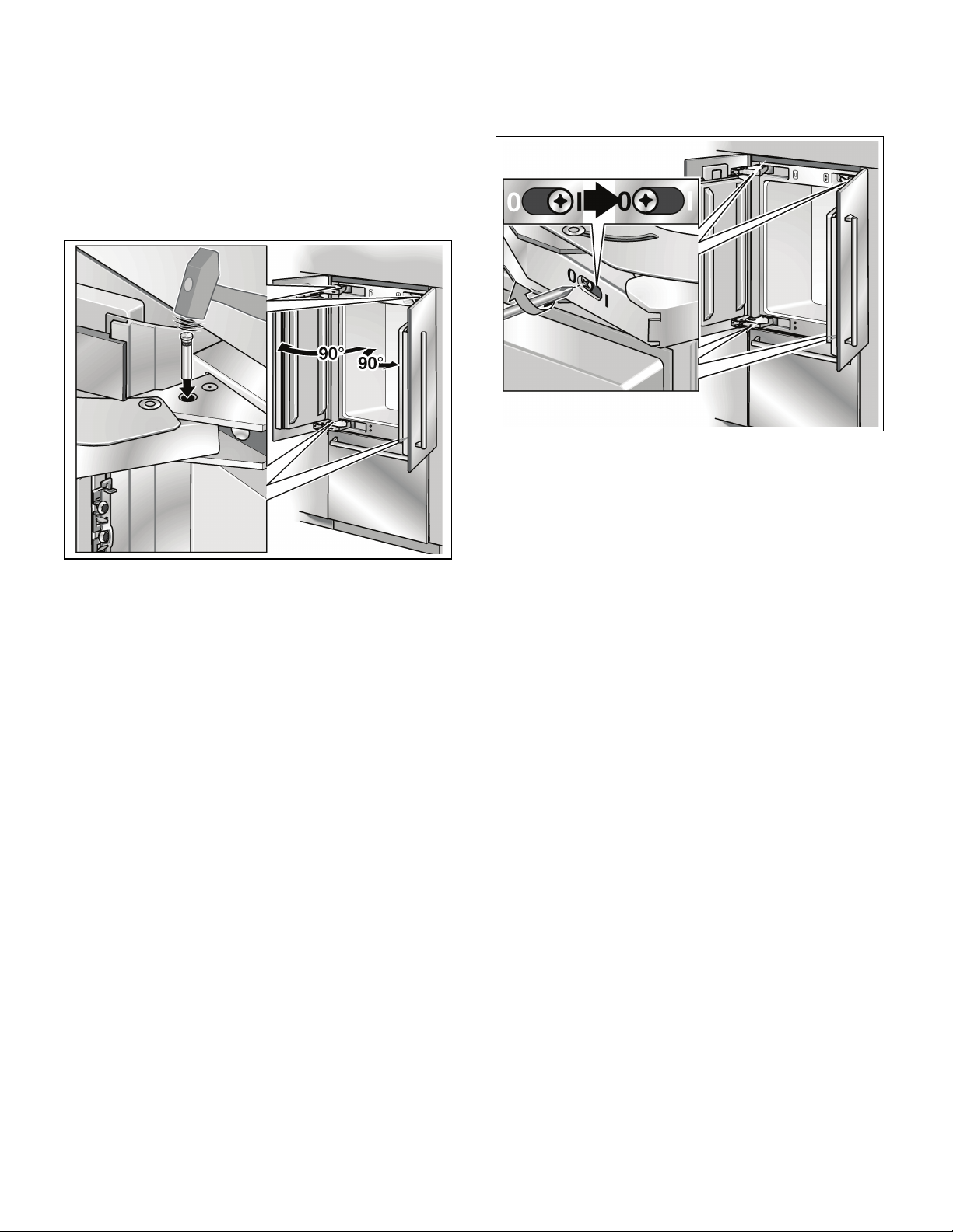
18. Ajustage de l'angle d'ouverture de
porte
Suivant les conditions d'installation, il pourra être nécessaire
d'ajuster l'angle d'ouverture de la porte. Un angle
d'ouverture de 115° a été ajusté en usine.
Pour conférer à la porte un angle d'ouverture de 90° :
Ouvrez la porte à 90°.
19. Changement du ressort de porte
Pour ajuster le ressort de porte :
A l'aide d'un tournevis à empreinte cruciforme, tournez
la vis d'ajustage.
I = Plus forte tension possible du ressort
0 =Pas de tension ressort
Introduisez la tige de limitation à travers les deux
alésages superposés puis enfoncez-la à l'aide d'un
marteau.
42

Índice
Antes de comenzar ..................................................................................................................................... 44
General ......................................................................................................................................................... 44
Definiciones .................................................................................................................................................. 44
Important information .................................................................................................................................... 44
Opciones de instalación ............................................................................................................................. 45
Unidad individual ........................................................................................................................................... 45
Electrodomésticos individuales con separación ............................................................................................. 45
En el final de las unidades de cocina ............................................................................................................. 45
Emplazamiento de la instalación ............................................................................................................... 46
Ambiente de emplazamiento ......................................................................................................................... 46
Cavidad de instalación .................................................................................................................................. 46
Muebles y adornos ....................................................................................................................................... 46
Base ............................................................................................................................................................. 46
Conexión a la red de alimentación ............................................................................................................ 47
Procedimiento de puesta a tierra adicional .................................................................................................... 47
Instrucciones de conexión a tierra ................................................................................................................. 47
Conexión del agua ...................................................................................................................................... 47
Medidas de instalación .............................................................................................................................. 48
Medidas del electrodoméstico ................................................................................................................... 49
Accesorios y herramientas necesarias ...................................................................................................... 50
Accesorios que forman parte del volumen de entrega ................................................................................... 50
Accesorios opcionales .................................................................................................................................. 50
Otros accesorios necesarios para salidas especiales .................................................................................... 50
Herramientas ................................................................................................................................................ 50
Otros ............................................................................................................................................................ 50
Instrucciones de instalación ...................................................................................................................... 51
1. Control de la cavidad para la instalación ................................................................................................ 51
2. Transporte del equipo ........................................................................................................................... 51
3. Desembalaje .......................................................................................................................................... 52
4. Preparativos para el montaje ................................................................................................................. 53
5. Preparación de la cavidad de instalación ............................................................................................... 53
6. Montaje de un dispositivo antivuelco adicional ....................................................................................... 54
7. Preparación para conectar el agua ........................................................................................................ 55
8. Protección de los bordes ....................................................................................................................... 55
9. Colocando el electrodoméstico en la cavidad de instalación .................................................................. 56
10. Desmontaje del frente de acero inoxidable de la gaveta del compartimiento de congelación ................. 57
11. Alineación del electrodoméstico ............................................................................................................ 57
12. Fijar el aparato en la cavidad de montaje ............................................................................................... 58
13. Conexión del agua al electrodoméstico ................................................................................................. 59
14. Sujeción del panel de protección ........................................................................................................... 59
15. Montaje del frente de acero inoxidable en la gaveta del com-partimiento de congelación ...................... 60
16. Puesta en marcha del equipo ................................................................................................................ 61
17. Montaje de las cubiertas ........................................................................................................................ 61
18. Ajuste del ángulo de apertura de la puerta ............................................................................................. 61
19. Cambio del muelle de la puerta ............................................................................................................. 62
43

Antes de comenzar
Lea estas instrucciones completamente y con detenimiento.
m ADVERTENCIA
La parte superior de este electrodoméstico es más pesada
que la de abajo, por lo que se lo debe asegurar a fin de evitar
que vuelque hacia delante. Se requiere de una protección
antivuelco.
Mantenga las puertas cerradas hasta que el electrodoméstico esté completamente instalado y asegurado
según las instrucciones de instalación.
Debido al peso y las dimensiones del electrodoméstico
y a fin de reducir el riesgo de lesiones personales o de daños
al producto – SE REQUIERE DE DOS PERSONAS PARA
UNA INSTALACIÓN ADECUADA.
Este electrodoméstico debe conectarse correctamente
a tierra. Consulte la sección «Conexión a la red de
alimentación».
Utilice el electrodoméstico exclusivamente para lo que ha
sido previsto.
Repare o cambie inmediatamente los cables eléctricos si
están gastados o dañados.
Desenchufe el electrodoméstico o desactive el fusible antes
de limpiar o efectuar reparaciones.
m ATENCIÓN
General
Las reparaciones debe efectuarlas un técnico calificado.
Estas instrucciones de instalación se entienden para se
usadas por instaladores calificados. Todas las conexiones
de agua, alimentación eléctricas y conexión a tierra, deben
cumplir con las prescripciones y ordenanzas locales y deben
ser realizadas por personal con las licencias
correspondientes si así se lo requiere. En ausencia de
prescripciones locales:
– En los E.E.U.U., de acuerdo con el National Electric
Code, ANSI/NFPA70 - última edición/prescripciones
municipales y/o locales.
– En Canadá, de acuerdo con el Canadian Electric Code
C22.1 - última edición prescripciones municipales y/o
locales..
Definiciones
m
ADVERTENCIA – indica que existe peligro de lesiones
graves y aún de muerte, que pueden ocurrir como
resultado de la inobservancia de esta advertencia.
ADVERTENCIA
m
Una instalación adecuada de este electrodoméstico requiere
de conocimientos específicos básicos en mecánica,
carpintería y fontanería.
Una instalación adecuada de este electrodoméstico requiere
de conocimientos específicos básicos en mecánica,
carpintería y fontanería. Fallos en el producto debido a una
instalación inadecuada no esta cubiertos por la garantía.
Consulte el manual del usuario por la información
concerniente a la garantía.
m IMPORTANTE
Guarde estas instrucciones para el uso del inspector local.
Tenga en cuenta todas las disposiciones y ordenanzas
gubernamentales.
Nota para instalador – Asegúrese de dejar estas
instrucciones al usuario.
Nota para el usuario – Guarde estas instrucciones con su
manual para el propietario.
m
ATENCIÓN – indica que pueden producirse lesiones
menores o daños que pueden ocurrir como resultado
de la inobservancia de esta advertencia.
ATENCIÓN
m
IMPORTANTE/NOTA
IMPORTANTE / NOTA – Este símbolo se utiliza para
llamar la atención del usuario respecto de algo en
particular.
Important information
No se puede enfatizar suficientemente la importancia de
cumplir con todas las disposiciones e instrucciones
contenidas en este manual. La instalación debe realizarla un
instalador calificado.
Antes de comenzar con la instalación, lea este manual
completamente. Contiene detalles importantes, que el
instalador debe observar. Siempre que se haya leído
prolijamente, la instalación será simple, sin problemas y ante
todo, segura.
44

Opciones de instalación
Las opciones de instalación limitadas exclusivamente por el
diseño de la cocina y la función de la protección para los
dedos.
Unidad individual
Electrodomésticos individuales con
separación
En el final de las unidades de cocina
Si uno de los lados del electrodoméstico está a la vista, debe
colocarse un panel lateral.
El panel lateral debe sujetarse firmemente en la pared, el piso
y el mueble o adorno superpuesto antes de colocar el
electrodoméstico en la cavidad.
Las dimensiones del panel lateral, deben tomarse en la
pared opuesta de la cavidad. Controle durante la instalación
que la cavidad esté a escuadra y que tenga las dimensiones
adecuadas.
– Si dimensiona los espacios para el modelo 2, tenga en
cuenta el espesor de los paneles frontales de los
muebles, a fin de evitar daños si se abren las dos
puertas simultáneamente.
– Utilice el Extreme Combination Heating kit (combinación
y calentamiento) si el espacio entre los dos
electrodomésticos es menor que 6" (160 mm).
Consulte la sección «Accesorios opcionales».
5
– La separación mínima debe ser de
/8" (16 mm).
45

Emplazamiento de la instalación
m
No instale el electrodoméstico:
– a la intemperie,
– en un ambiente donde gotee agua,
– en ambientes donde existe peligro de heladas.
El electrodoméstico es muy pesado. Por los pesos del
equipo vacío, consulte la tabla siguiente:
Bottom Freezer 36"
(Congelador independiente) aprox. 430 Ibs/195 kg
ADVERTENCIA
m
Ambiente de emplazamiento
El electrodoméstico debe instalarse en un ambiente seco
y bien ventilado.
La temperatura el ambiente no debe descender de
los 55 °F (13 °C) o aumentar más allá de los 110 °F (43 °C).
De lo contrario puede no funcionar correctamente.
El lugar de emplazamiento no debe estar expuesto a la luz
solar directa, ni cerca de una fuente de calor como una
estufa, radiador, etc.
Si es inevitable instalarlo cerca de una fuente de calor, utilice
una placa aislante adecuada o asegure una distancia mínima
respecto de la fuente de calor:
1
–1
/4" (30 mm) de un horno eléctrico,
– 12" (300 mm) de un horno a aceite o combustible seco.
Muebles y adornos
El electrodoméstico debe atornillarse firmemente a los
muebles o adornos adyacentes y superpuestos.
A tal fin es esencial que todos los muebles o adornos estén
firmemente sujetos al suelo o las paredes con medios
adecuados.
Base
m
Un electrodoméstico plenamente cargado es muy
pesado. Consulte la tabla siguiente para la carga total
requerida de la base:
BM (Bottom Mount) 36"
(Congelador independiente) aprox. 1200 lbs/540 kg
Para asegurar que el electrodoméstico esté firmemente
montado y funcione correctamente, la base de apoyo debe
ser plana y horizontal.
La base debe ser de material duro y rígido.
La zona de instalación deben presentar la misma altura que
el resto del ambiente.
Para dar cuenta del elevado peso del electrodoméstico
plenamente cargado, se requiere que la base resista la carga
en cuestión. Si tiene dudas, consulte a un arquitecto
o experto en construcción.
ADVERTENCIA
m
Cavidad de instalación
Es importante observar las dimensiones especificadas para
la cavidad de instalación a fin de garantizar una instalación
del electrodoméstico sin problemas y para una vista general
adecuada del mueble.
Controle particularmente que la cavidad esté a escuadra.
Esto puede controlarse con herramientas adecuadas, como
un nivel de agua, mediciones en diagonal, etc.
Las paredes laterales de la cavidad deben ser planas.
El espesor mínimo de las paredes laterales y la pared
superior debe ser de
El espesor mínimo de panel de protección debe ser
1
de
/2" (13 mm). Se recomienda un espesor de 3/4" (19 mm).
5
/8" (16 mm).
46

Conexión a la red de alimentación
m
¡ Peligro de descargas eléctricas !
– Conéctelo a un tomacorriente de 3 conductores con
conexión a tierra.
– No desconecte el contacto de toma de tierra.
– No utilice adaptadores.
– No utilice cables de prolongación.
El incumplimiento de estas instrucciones puede ser
causa de la muerte, incendios o descargas eléctricas.
El electrodoméstico se entrega con un conductor de
alimentación de 3 cables, listado según UL.
El electrodoméstico requiere de un tomacorriente de
3 conductores.
Este tomacorriente debe instalarlo un electricista con la
licencia debida.
La toma de corriente tiene que estar protegida con un fusible
de 10–16 amperios. Rogamos tener en cuenta a tal fin,
la tabla siguiente:
Electrodoméstico Carga simultánea máxima
Bottom Freezer 36“
(Congelador independiente)
Oriente el borne de puesta a tierra hacia abajo según se
muestra en las figuras.
Por la ubicación de los tomacorrientes, consulte las
«Medidas de instalación» en página 48.
ADVERTENCIA
6Amper
Procedimiento de puesta a tierra
adicional
Algunas disposiciones locales exigen una puesta a tierra
adicional. En este caso debe adquirirse por separado el
cable, las grampas y los tornillos accesorios.
Nunca conecte a tierra el electrodoméstico en tuberías de
plástico, de gas o de agua.
m
Instrucciones de conexión a tierra
Este electrodoméstico debe conectarse a tierra.
En caso de un fallo en el funcionamiento o una rotura, la
conexión a tierra reduce el riesgo de descargas eléctricas,
proveyendo una vía de resistencia menor para la corriente
eléctrica.
m
Una conexión inadecuada del conductor de puesta a
tierra puede ser causa de una descarga eléctrica.
Haga controlar el electrodoméstico por un electricista
calificado o personal del servicio técnico si tiene dudas
respecto de una conexión a tierra correcta.
ADVERTENCIA
m
Conexión del agua
m
¡Conectar el electrodoméstico exclusivamente a una
tubería de agua potable!
Se requiere de una conexión de agua fría, para el
funcionamiento del generador automático de hielo.
La presión del agua debe estar comprendida entre
25 a 120 p.s.i. (1,72 a 8.25 bar).
La instalación debe cumplir con las reglamentaciones de
tubería de agua locales y las leyes nacionales
correspondientes.
Debe instalarse una válvula de cierre en la conexión de agua
del electrodoméstico.
La válvula de cierre no debe encontrarse detrás del
electrodoméstico. Se recomienda instalar dicha válvula en la
cercanía inmediata del electrodoméstico (unidad base) o en
otra zona de fácil acceso.
Durante la instalación del agua, observe las zonas de
instalación permitidas para la tubería. Por las zona
mencionadas y sus medidas, consulte «Medidas de
instalación».
La tubería de alimentación puede ubicarse al costado
derecho (a), al costado izquierdo (b), o debajo (c).
El diámetro externo máximo dela tubería
(sin las monturas):
Sujete la válvula para la conexión de agua, en un sitio de fácil
acceso.
¡No utilice una válvula de conexión por perforado!
ATENCIÓN
13
/32" (10 mm).
m
47

Medidas de instalación
`зеЙсбμå=ÇÉä=~Öì~
Instalación simple
Leyenda:
A Zona para la conexión a la red de potencia
B Zona para la instalación de la conexión de agua
C Altura de la abertura, según el diseño de la cocina
D = 24" (610 mm) como mínimo
Nota: La cavidad debe estar a escuadra.
La pared lateral de la cavidad debe ser plana
48

Medidas del electrodoméstico
Leyenda:
a) Ajuste con patas niveladoras
b) Las medidas pueden varias.
d) Esta medida puede variar dependiendo de la instalación,
3
/8" (35 mm) / –1/2" (13 mm)
+1
el espesor del panel y el equipamiento de la cocina
e) Medidas de la unidad
f) Medidas del panel puerta
49

Accesorios y herramientas necesarias
Accesorios que forman parte del
volumen de entrega
– Instrucciones para el montaje
– Instrucciones de funcionamiento
– Juego de instalación
Accesorios opcionales
Extreme Combination Side-by-Side Heating kit
(combinación lado a lado y calentamiento)
Si el espacio entre los electrodomésticos es menor que 6"
(160 mm).
Otros accesorios necesarios para salidas
especiales
Juego para la instalación de un generador de hielo con
línea de
Para electrodomésticos que requieren agua. P. ej. para un
generador de hielo.
1
/4" de cobre
Diámetro máximo de la tubería de agua (sin
accesorios):
13
/32" (10 mm).
Herramientas
– Destornillador a batería T20
– Destornillador tipo Torx T20
– Bit tipo Torx T20 + un soporte magnético
– Destornillador de ranura en cruz
– Brocas para madera de diversas medidas
1
– Llave de boca
–Pinza universal
–Llave ajustable
– Cuchilla de hoja ajustable
– Cinta de medir metálica
–Escuadra
– Nivel de agua de 2' (60 cm) y 4' (1,2 m)
– Nivel marcador, con una longitud mínima de 4' (1,2 m)
para electrodomésticos individuales o 7' (2,0 m) para
instalación Side-by-Side (Lado a lado).
/2" (SW 13 mm)
5
/16" (8 mm)
Otros
– Escalera
– Carro de mano
– Perforadora para practicar orificios en paredes o pisos.
– Bits de diferentes tamaños y materiales.
– Viguetas de madera (sección transversal mínima de 3“
x 4" (75 mm x 100 mm)) como protección alternativa
contra vuelcos, de longitud adecuada al ancho de la
cavidad.
– Tornillos de madera de diferentes tamaños
1
– Material delgado (máx.
evitar daños en el piso (p. ej. linóleo)
– Material adecuado para cubrir y proteger los muebles
(p. ej. láminas de protección).
–Cinta adhesiva.
/16" (1.5 mm)), adecuado para
IMPORTANTE
Verificar antes de usar la cinta adhesiva si ésta deja
restos de adhesivo en las superficies de los componentes. En caso de que así fuera, no deberá
usarse en aparatos con superficies delicadas y de
alta calidad.
50

Instrucciones de instalación
1. Control de la cavidad para
la instalación
m
Para asegurar una instalación sin problemas y una
vista adecuada del frente del mueble a instalar,
controle prolijamente la cavidad para que la instalación
cumpla con los requerimientos del caso.
Para asegurar una instalación sin problemas y una vista
adecuada del frente del mueble a instalar, controle
prolijamente la cavidad para que la instalación cumpla con
los requerimientos del caso.
Controle la base.
Siga las instrucciones de la sección «Emplazamiento de
la instalación» en página 46.
Controle las medidas de la cavidad.
Controle que la cavidad esté a escuadra.
Controle la ubicación del tomacorriente.
Siga las instrucciones de la sección «Conexión a la red
de potencia» en página 65 y la sección «Medidas de
instalación» en página 66.
Controle la ubicación de la conexión del agua
(únicamente en caso de electrodomésticos con
generador de hielo).
Siga las instrucciones de la sección «Conexión del
agua» en página 47.
Controle la sujeción de los muebles o adornos
adyacentes. Todos los muebles en las cercanías del
electrodoméstico deben estar firmemente sujetos a las
paredes.
Controle que los muebles o adornos adyacentes no
colisionen (ángulo de apertura de las puertas).
ATENCIÓN
m
2. Transporte del equipo
m
El equipo es muy pesado. Por ello debe tenerse
especial cuidado, ya que eventuales colaboradores
pueden verse lesionados o el equipo puede sufrir
daños.
Transportar el equipo con elementos de transporte
adecuados al sitio de emplazamiento y al equipo mismo
(carretilla para sacos, elevador a horquillas o carro).
Asegurar el electrrodoméstico para que no pueda
volcarse durante el transporte.
El equipo presenta una altura de 86“ (2185 mm). Si no se
puede transportar el equipo en posición vertical, debido a las
características constructivas del sitio, puede transportárselo
acostado.
Tener en cuenta la altura mínima necesaria en el sitio de
emplazamiento cuando se quiere parar el equipo, siguiendo
los datos de la tabla siguiente:
Parar el equipo por la
pared posterior
86“ / 2185 mm ¡No colocar el aparato
ATENCIÓN
Parar el equipo por la
pared lateral
nunca en posición vertical
por uno de sus laterales!
m
51

3. Desembalaje
A
B
B
m
ATENCIÓN
m
m
– El electrodoméstico puede volcar durante el
desembalaje.
– El electrodoméstico es extremadamente pesado.
– El electrodoméstico puede volcar hacia delante,
cuando abra la puerta del mismo.
Sea cuidadoso, de otra manera puede lesionarse la
gente que le ayuda, o puede dañarse el electrodoméstico.
Para proteger la base de daños durante la instalación:
Sujete un trozo de paño, linóleo, etc. delante del sitio de
emplazamiento.
ADVERTENCIA
m
No quite el seguro de transporte (A) de la parte inferior
del cajón que se encuentra en el gabinete de
congelación.
No dañe la protección para los dedos (B) durante los
pasos a efectuar a continuación.
No quite los dispositivos de protección para el
transporte de los estantes y las gavetas, antes de
concluir con la instalación. De lo contrario pueden
dañarse.
Mueva el electrodoméstico mediante un carrito de
mano.
Quite el embalaje de transporte:
– Quite el cartón.
Utilice la cuchilla con cuidado para no rayar el
electrodoméstico.
– Sujete el cable de conexión a la red en la parte
posterior del electrodoméstico mediante una cinta
adhesiva.
– Afloje el seguro de transporte y quite el
electrodoméstico de la paleta –
¡El electrodoméstico es pesado!
– Quite los accesorios sujetos en la parte exterior del
electrodoméstico.
– Conserve las cintas adhesivas con las cuales
estaban sujetos los accesorios en el electrodoméstico que forman parte del volumen de
entrega. Sirven para la posterior sujeción de la
protección para los bordes en las paredes de la
cavidad (ver la sección 8.).
– Abra cuidadosamente el electrodoméstico – peligro
de vuelco – extrayendo los accesorios y el material
para el montaje que se encuentran en el interior.
¡Vuelva a cerrar el electrodoméstico!
Controle si el electrodoméstico presenta daños de
transporte.
No instale el electrodoméstico si presenta daños
visibles. En caso de dudas, consulte con su vendedor.
m
¡Prestar atención al cerrar la puerta!
Al cerrar la puerta, el larguero montado en la puerta
izquierda tiene que estar abatido, de lo contrario se
pueden producir daños en el aparato o en el panel
frontal del mueble.
ATENCIÓN
m
52

4. Preparativos para el montaje
Desembalar el material de montaje y los accesorios.
Con objeto de facilitar su identificación y posterior
asignación a los diferentes pasos de trabajo, los embalajes
tienen distintos colores.
¡Prestar atención a este efecto a la hoja orientativa sujeta el
aparato!
5. Preparación de la cavidad
de instalación
¡La longitud de la madera debe estar de acuerdo con el
ancho del espacio disponible para la instalación!
Determine los puntos de sujeción para los ángulos
antivuelco.
Determine las medidas en detalle, consultando la sección
«Medidas de instalación».
Sujete completamente los ángulos antivuelco.
Asegúrese que los tornillos estén firmes.
Sujeción mediante tronillos para madera
m
Asegure que no existan cables eléctricos o tuberías en
la zonas donde deben penetrar los tornillos. ¡Existe
peligro de lesiones y daños!
ADVERTENCIA
m
IMPORTANTE
– Se requiere de dos ángulos antivuelco para cada
electrodoméstico.
– El juego suministrado comprende diversos tronillos
para diferentes instalaciones. Seleccione los
tornillos de acuerdo a las condiciones.
Los ángulos antivuelco deben presentar una longitud mínima
sobe el electrodoméstico de 4
asegurar un emplazamiento seguro del equipo.
Si no se puede dar cumplimiento a esta longitud mínima
debido a condiciones estructurales, puede lograrse ésto,
sujetando un espaciador detrás del ángulo antivuelco,
es decir un trozo de madera de dimensiones suficientes.
1
/8” (105 mm) a fin de
53

Sujeción mediante tarugos y tornillos
m
Utilice siempre gafas y otros dispositivos de protección
cuando instala o trabaja con tarugos. ¡Peligro de lesiones!
No recomendado par ser usado en material de mampostería
liviana como bloques y ladrillos.
No recomendado para ser usado en cemento fresco que no
ha tenido tiempo de fraguar.
No utilice brocas huecas para practicar perforaciones para
los tarugos.
ATENCIÓN
m
6. Montaje de un dispositivo antivuelco
adicional
IMPORTANTE
Si no se pueden montar los soportes antivuelco con la
firmeza requerida, puede montarse un dispositivo
antivuelco alternativo. Sin embargo, debe asegurarse,
de que no exista juego entre el electrodoméstico y el
dispositivo antivuelco.
Si es posible, atornille las viguetas de madera sobre
monturas ya existentes en la pared de la cavidad.
Corte la vigueta de madera (seción transversal
min. 3" x 4") a la longitud requerida.
¡La longitud debe ser igual a la anchura de la cavidad de
instalación!
NOTA
– Si la cavidad de instalación es más profunda que
el electrodoméstico, selecciones una vigueta que
presente una sección transversal mayor, o monte
dos viguietas.
– La vigueta debe exceder el electrodoméstico
en un mínimo de 2" (50.8 mm).
54
Marque la altura de instalación (esquina inferior de la
madera) sobre el panel posterior de la cavidad.
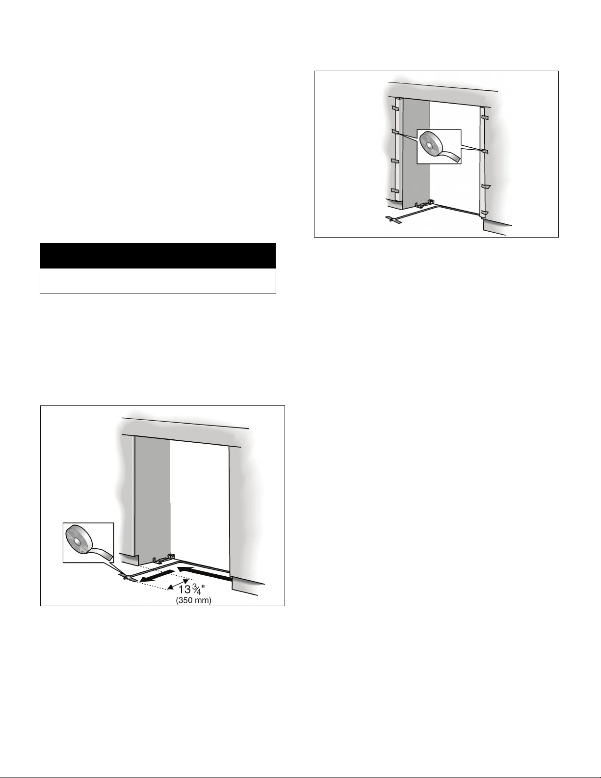
Seleccione los tornillos de acuerdo al espesor de la
vigueta de madera: longitud = mín. 2,5 x el espesor de
la vigueta, diámetro # 12 o # 14.
Especifique la cantidad de tornillos, de acuerdo al
ancho de la cavidad, asegurando que la vigueta quede
montada firmemente.
Ubique la pared vertical cerca de la pared posterior de
la cavidad y marque las perforaciones en la vigueta.
Perfore previamente la vigueta de madera.
Sujete la vigueta de madera en la pared posterior de la
cavidad.
7. Preparación para conectar el agua
(solamente si el electrodoméstico requiere de una
conexión de agua)
8. Protección de los bordes
m
Cierre la llave principal de agua, a fin de evitar daños
debidos a la pérdida de agua.
Monte la tubería de conexión a la válvula de cierre,
según las instrucciones suministradas por el fabricante
de la instalación generadora de hielo.
Instale la tubería de conexión.
Observe siempre las medidas de separación indicadas,
a fin de evitar daños en la tubería de conexión, cuando
coloca el electrodoméstico en su sitio.
ATENCIÓN
m
Para proteger la hornacina, sujete los ángulos de
protección con cinta adhesiva en las esquinas.
Sujete la tubería de conexión al suelo con cinta
adhesiva.
55

9. Colocando el electrodoméstico en la cavidad de instalación
Introducir el aparato cuidadosamente en la cavidad de
m
¡Tenga cuidado al empujar el electrodoméstico
al interior de la cavidad!
– No dañe la tubería de agua o el cable de alimenta-
ción sujetos al suelo.
– Controle la protección para los dedos de ambos
lados, mientras coloca el electrodoméstico en la
cavidad. Controle su función inmediatamente
después de la colocación, abriendo y cerrando las
puertas.
ATENCIÓN
m
montaje. ¡Prestar atención a no ladearlo! Desplazarlo en
la cavidad de montaje hasta que el bastidor esté en
contacto con las paredes de la cavidad.
IMPORTANTE
Si el piso o el electrodoméstico es inclinado respecto
de la cavidad de instalación, ajuste las ruedas
ajustables en altura, antes de introducir el
electrodoméstico en la cavidad.
Conecte el enchufe en el tomacorriente.
Cuide de no dañar el cable de alimentación.
Sujete un pedazo de hilo en el medio del cable,
llevándolo hacia delante debajo del electrodoméstico.
Cuando introduzca el electrodoméstico, tire el cable
hacia delante.
o bien
Pegue el cable mediante cinta adhesiva en el suelo
detrás del electrodoméstico a una distancia aprox. de
15" (380 mm) de la pared posterior de la cavidad.
56
Quitar la protección para los bordes.
Quite el seguro de transporte de la parte inferior de la
gaveta del compartimiento de congelación.
Controle la función de la protección para los dedos.
Abra y cierre ambas puertas. La protección para los
dedos debe deslizarse con facilidad hacia el interior de
la ranura comprendida entre el electrodoméstico y la
pared de la cavidad.

10. Desmontaje del frente de acero
inoxidable de la gaveta del
compartimiento de congelación
Afloje las tuercas en la parte superior de la puerta y desenrósquelas. Evite durante este proceso, girar los pernos
roscados, a fin de mantener la orientación de la puerta.
Afloje los tornillos de los ángulos de sujeción a la derecha
y a la izquierda. ¡No desenrosque totalmente los tornillos!
11. Alineación del electrodoméstico
m
¡Nunca utilizar un destornillador a batería!
ATENCIÓN
IMPORTANTE
– ¡No gire o presione el electrodoméstico dentro de
la cavidad! Cuando desenrosque las patas de altura
ajustable, proceda de modo gradual: alterne
siempre entre la derecha y la izquierda, repitiendo el
proceso alternativamente.
– El ajuste de las patas posteriores se facilita si se
descarga la parte posterior del equipo.
– Si utiliza una vigueta de madera como dispositivo
antivuelco alternativo, según se describe en el
punto 6. de este manual de instalación, rote el
electrodoméstico totalmente hacia la vigueta de
madera.
m
Retire el frente de acero inoxidable en su parte inferior
tirando de él, a fin de separar los tornillos de los ángulos de
sujeción. Quite ahora la puerta de los pernos roscados,
levantándola.
Los ángulos de sujeción se encuentran calados sin fijarlos
dentro de las pieza de unión, a fin de evitar que se pierdan.
Desmonte el revestimiento del zócalo del electro-
doméstico.
Alinee el electrodoméstico con los frentes de los
muebles.
Las ruedas de altura ajustable tanto del frente como de la
parte posterior, pueden ajustarse desde el frente.
1
Frente: llave de boca de
Fondo: destornillador en cruz
flexible.
Como medida sugerida para el ajuste de la altura, se ha
practicado una marca en la pata del equipo. Durante el
ajuste, esta marca debe ajustarse esta marca a una altura de
1
/4" (32 mm) sobre el nivel del suelo.
1
/2" (SW13)
5
/16" (8 mm) con vástago
57

Desenrosque las patas de altura ajustable hasta que la
marca en la base logre la medidas indicadas (1
1
/4" / 32 mm).
NOTA
Es sumamente importante cumplir con estas
medidas, para lograr una buena alineación de los
frentes de los muebles.
Alinee los frentes de los muebles con el nivel de agua.
Antes de fijar el aparato definitivamente en la cavidad de
montaje, verificar:
– si el bastidor del aparato está en contacto por arriba
y por abajo con el frontal de la cavidad de montaje,
12. Fijar el aparato en la cavidad de
montaje
Abrir una puerta del compartimiento frigorífico.
Retirar la protección de los dedos completamente de la
rendija entre el aparato y la pared de la cavidad de montaje.
– el funcionamiento de la protección de los dedos
abriendo y cerrando repetidas veces las dos puertas
del compartimento frigorífico.
Atornillar el bastidor a la pared de la cavidad de montaje
a través de la rendija entre la puerta y el cuerpo del aparato
(3 tornillos)
Atornillar el bastidor a la pared de la cavidad de montaje por
debajo del cajón de congelación (1 tornillo)
Abrir la otra puerta del compartimento frigorífico y retirar la
protección de los dedos de su emplazamiento. Atornillar el
bastidor a la pared de la cavidad (4 tornillos).
Introducir la protección de los dedos, a través de la escotadura del bastidor, en la rendija entre el aparato y la pared
de la cavidad.
58

13. Conexión del agua al
electrodoméstico
m
Cuando conecte la tubería de agua, no la retuerza.
De lo contrario existe el riesgo que se produzcan
pérdidas de agua. Utilice los elementos auxiliares para
el doblado.
ATENCIÓN
m
IMPORTANTE
Cuando conecte la tubería de agua a la válvula solenoide del electrodoméstico, siga las instrucciones provistas por el fabricante conjuntamente con el kit de
montaje del generador de hielo que se incluyen en este
manual.
Quite la capa de la conexión del electrodoméstico (1.).
Doble la tubería de agua de acuerdo con la ubicación de
la conexión del electrodoméstico (2.).
Empuje la tuerca de unión, sellando la unión sobre la
tubería de agua.
Empuje el extremo de la tubería de agua, hasta que
penetre en la conexión del electrodoméstico y enrosque
la tuerca de unión (3.). Ajuste con la mano.
Ajuste la tuerca de unión mediante la llave de boca.
¡No fuerce la rosca!
14. Sujeción del panel de protección
m
La altura máxima del panel de protección sobre el
suelo es de 4". No obture las aberturas de ventilación
en el base del panel. Existe riesgo de daños en el
electrodoméstico.
Si hace falta, corte el panel de protección a la longitud
necesaria.
Monte el panel base en el electrodoméstico.
ATENCIÓN
m
Abra la válvula de cierre y la llave general. Controle la
válvula de cierre y la conexión en el electro-doméstico,
para localizar eventuales pérdidas.
Quite la lámina de protección de la almohadilla adhesiva
del Velcro.
Coloque el panel de protección en el panel base,
presionando firmemente.
Aplique el panel base (sin atornillar) y mida la diferencia
Y entre el panel base y el panel de protección del
mueble adyacente.
Quite el panel base.
Afloje los soportes de sujeción del panel base y empuje
hasta el fondo.
59

15. Montaje del frente de acero inoxidable
en la gaveta del com-partimiento de
congelación
Extraiga las mordazas en la medida Y determinada.
Atornille las mordazas firmemente.
Monte el panel base.
NOTA
Si hace falta, puede atornillar el panel de protección al
panel base. Existen perforaciones para los tornillos en
el panel base, cerca de los Velcros.
Cuelgue el frente de acero inoxidable de los pernos
roscados.
Levante la parte inferior del frente de acero inoxidable,
seprándolo de la puerta del compartimiento de
congelación, deslizando los ángulos de sujeción de
arriba hacia abajo sobre los tornillos.
Controle la altura del frente de acero inoxidable con
respecto de los frentes de los muebles vecinos,
estando la gaveta cerrada.
Si el ajuste en altura es correcto, ajustar los tornillos de
los ángulos de sujeción.
60
Enrosque las tuercas sobre los pernos roscados en la
parte superior de la puerta. No las ajuste aún.
Controle la orientación lateral del frente de acero
inoxidable. Si esta orientación es correcta, ajuste las
tuercas.

16. Puesta en marcha del equipo
m
Controle el funcionamiento de la protección de los
dedos. Verifique en particular
– si la protección de los dedos está correctamente
fijada al aparato y
– si la protección de los dedos se desliza con faci-
lidad hacia adelante y atrás al abrir y cerrar las
puertas del compartimento frigorífico.
A fin de garantizar la exactitud de los pasos a realizar a
continuación ya que tendrán influencia en la imagen de
apariencia de todo el frente de la cocina, ahora debe
ponerse en marcha el equipo.
Abra la puerta del electrodoméstico.
Accione el pulsador POWER.
Únicamente para equipos que disponen de una conexión de
agua:
ATENCIÓN
m
NOTA
A fin de evitar eventuales daños debidos al agua que
pueda surgir en caso de una avería de la tubería correspondiente, debe dejarse todavía cerrado el grifo del
agua.
Coloque la placa de cobertura en la puerta del
compartimiento congelador.
18. Ajuste del ángulo de apertura de la
puerta
Dependiendo de las condiciones de instalación, puede ser
necesario ajustar el ángulo de apertura de la puerta. En
fábrica se ha ajustado un ángulo de apertura de 115°.
A fin de ajustar el ángulo de apertura a 90°:
Abrir la puerta a 90°.
17. Montaje de las cubiertas
Encajar los listones de cobertura, por el lado de los
tiradores de las puertas, en la rendija entre el frontal de
acero inoxidable y la puerta del aparato.
Encajar los listones de cobertura del cajón de
congelación en la rendija entre el frontal de acero
inoxidable y el cajón.
Introducir el perno ¡imitador a través de las dos perforaciones ahora enfrentadas, golpeando con un martillo.
61

19. Cambio del muelle de la puerta
A fin de ajustar el muelle de la puerta.
Girar del tornillo de ajuste mediante un destornillador
para ranura en cruz.
I = aumenta la tensión del muelle
0 = disminuye la tensión del muelle
62

63

Robert Bosch Hausgeräte GmbH
Carl-Wery-Straße 34
81739 München
www.bosch-hausgeraete.de
9000 561 801 (9006)
en–us, fr–ca, es–mex
 Loading...