

Bosch ARD-AYCE65B Installation Manual
ARD-AYCE65B
RFID - Proximity Card Reader
en Installation manual


ARD-AYCE65B Table of Contents | en 3
Table of Contents
1 General Information 5
1.1 Introduction 5
1.2 Box Content 5
2 Technical Specifications 6
2.1 Key Features 7
3 Installation 8
3.1 Mounting the ARD-AYCE65B 8
4 Wiring Instructions 9
5 Reader Functionality 11
5.1 Transmit Mode 11
5.2 Programming the ARD-AYCE65B Series 11
5.3 Selecting Keypad Transmission Format 13
5.3.1 Option No. 1: Single Key, 6-Bit Wiegand 15
5.3.2 Option No. 2: Single Key, 6-Bit Wiegand Nibble and Parities 15
5.3.3 Option No. 3: Single Key, 8-Bit Wiegand Nibbles Complemented
16
5.3.4 Option No. 4: 4 Keys Binary + Facility Code, 26-Bit Wiegand 16
5.3.5 Option No. 5: 1 to 5 Keys + Facility Code, 26-Bit Wiegand 17
5.3.6 Option No. 6: 6 Keys BCD and parity bits, 26-Bit Wiegand 18
5.3.7 Option No. 7: Single Key, 3x4 Matrix Keypad (ARD-MDP64) 19
5.3.8 Option No. 8: 1 to 8 Keys BCD, Clock & Data 19
5.4 Selecting Proximity Card Transmission Format 20
5.5 "Wiegand Card + PIN" Transmission Format 21
5.6 Changing the Programming Code 22
5.7 Changing the Facility Code 23
5.8 Setting the Backlight 23
5.9 Return to Factory Default Settings 24
5.10 Replacing a Lost Programming Code 24
Bosch Sicherheitssysteme GmbH Installation manual | V 1.1 | 2009.08

4 en | Table of Contents ARD-AYCE65B
6 Appendix 25
6.1 LED displays 25
6.2 Technical Support 27
| V 1.1 | 2009.08 Installation manual Bosch Sicherheitssysteme GmbH

ARD-AYCE65B General Information | en 5
1 General Information
1.1 Introduction
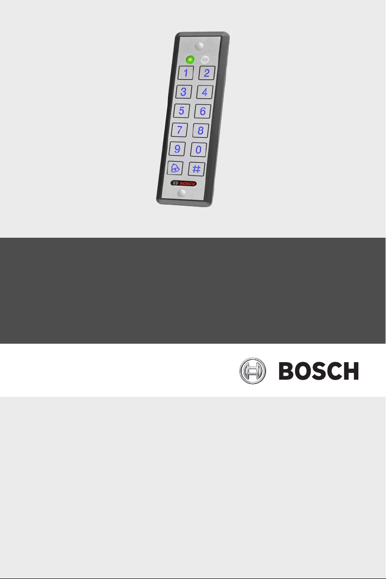
The ARD-AYCE65B family is an Ultra-slim, vandal-resistant,
Piezo Mullion Keypad, access control reader.
The unit is vandal resistant and water resistant, suitable for
indoor or outdoor mounting.
This manual contains the following information:
– Installation
– Wiring instructions
–Operation Instructions
1.2 Box Content
Before beginning verify that all of the following is in the box. If
anything is missing, please report the discrepancy to your
nearest Bosch office.
– One ARD-AYCE65B unit
– Installation kit
– Installation and operating instructions
Bosch Sicherheitssysteme GmbH Installation manual | V 1.1 | 2009.08

6 en | Technical Specifications ARD-AYCE65B
2 Technical Specifications
Specifications ARD-AYCE65B
Electrical Characteristics
Power supply type Linear type - recommended
Operating voltage range 5 - 16VDC
Input current standby 92mA@12VDC
max Input current 105mA@16VDC
LED control input Dry contact N.O.
Tamper output Open collector, active low, 30mA
max sink current
Cable distance to host
controller
Max proximity card read
range*
Proximity card
modulation
Proximity card
compatibility
Card Transmit format
(Reader)
Keypad Transmit Format
(Reader)
LED indicators Two tri-colored LEDs
Communication Data1/Clock, Data0/Data- TTL
Environmental Characteristics
Operating temp. range -30 to 65° C (-22 to 150° F)
Operating humidity 0 - 95% (non-condensing)
Outdoor usage Weather-resistant, meets IP-68,
Mechanical
Up to 500ft (150 meters) using an
18AWG cable
40mm (1.575 inch)
ASK at 125 KHz
EM cards
26-bit Wiegand, or Clock & Data
Programmable PIN code formats
output
epoxy potted, suitable for outdoor
use
| V 1.1 | 2009.08 Installation manual Bosch Sicherheitssysteme GmbH

ARD-AYCE65B Technical Specifications | en 7
Specifications ARD-AYCE65B
Size
(Height x Width x Depth)
Weight 143g(0.315lb)
*Measured using Bosch proximity card (ACD-ATR14CS) or
equivalent. Range also depends on electrical environment and
proximity to metal.
155 x 44 x 9mm
6.1x1.73x0.354 inch
2.1 Key Features
The key features for the ARD-AYCE65B series are:
– Ultra-Slim Flush-mount design on flat surface
– Built-in piezoelectric keypad for PIN code entry
– Built-In 125 KHz ASK EM Proximity card reader
– Programmable Patented Blue backlit keypad
– Optical back tamper sensor and open collector tamper
output.
– Internal buzzer provides audible interface feedback
– Two status / programming Interface LEDs (tri-colored)
– Fully potted construction for outdoor use
– Comes with mounting template for easier installation
– Comes with an installation kit that includes a security
screw and a security screw tool
Reader
– Programmable keypad transmission format
– Programmable Card Transmission Formats: Clock & Data
and 26-Bit Wiegand
–LED control input
– Programmable facility code
Bosch Sicherheitssysteme GmbH Installation manual | V 1.1 | 2009.08
8 en | Installation ARD-AYCE65B
3 Installation
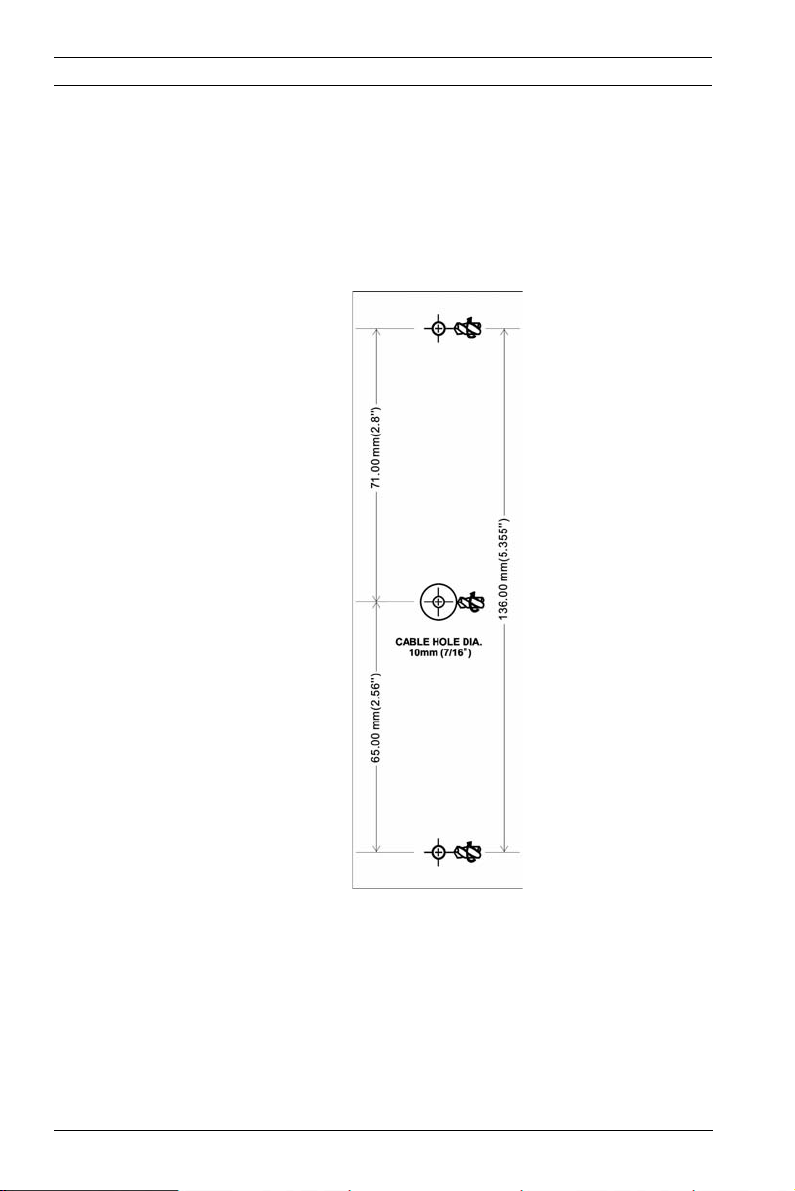
Before starting, select the location to mount the ARD-AYCE65B.
This location should be at shoulder height.
For wall mounting, use the included mounting template as a
guide for drilling holes for mounting screws and wiring. For US
Gang Box mounting, no drilling is necessary.
Figure 3.1 Drilling & Mounting Template
Route the interface cable from the ARD-AYCE65B to the
controller. A linear type power supply is recommended.
Screw the ARD-AYCE65B to its mounting location or US gang
box.
| V 1.1 | 2009.08 Installation manual Bosch Sicherheitssysteme GmbH

ARD-AYCE65B Wiring Instructions | en 9
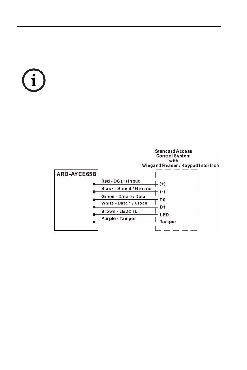
4 Wiring Instructions
The unit is supplied with a 1.5 meter (60-inch) pigtail, having a
6-conductor cable. To connect the unit to the controller,
perform the following:
Prepare the unit's cable by cutting the cable jacket back 1¼
inches and strip the wire ½ inch. Prepare the controller cable
by cutting the cable jacket back 1¼ inches and strip the wire ½
inch.
Splice the unit's pigtail wires to the corresponding controller
wires and cover each connection.
Refer to the wire color table below, and to the wiring diagram
provided on the following page.
Reader Color Functionality
5~16 VDC Red +DC Input
Shield/ Ground Black Ground
Data 1 / Clock White Communication
Data 0 / Data Green Communication
LEDCTL Brown LED Control / Auxiliary Input
Tamper Purple Tamper
If the tamper output is used, connect the purple wire to the
correct input on the controller.
Trim and cover all unused conductors.
Bosch Sicherheitssysteme GmbH Installation manual | V 1.1 | 2009.08
10 en | Wiring Instructions ARD-AYCE65B
NOTICE!
– The individual wires from the unit are color-coded
according the Wiegand standard.
– When using a separate Power Supply for the Reader, this
Power Supply and that of the Controller must have a
common ground.
– The Reader's cable shield wire should preferably be
attached to an earth ground, or a signal ground connection
at the panel, or power supply end of the cable. This
configuration is best for shielding the Reader cable from
external interference
Figure 4.1 Reader Application Wiring Diagram
| V 1.1 | 2009.08 Installation manual Bosch Sicherheitssysteme GmbH
 Loading...