

Bosch AGS10-2, AGS20-2, AGS10E-2, AGS50-2 Installation And Servicing Instructions
Solar pump station for solar thermal systems
AGS10-2, AGS10E-2, AGS20-2, AGS50-2
Installation and servicing instructions
6 720 811 270 (2015/04) UK
2 | Table of contents
Table of contents
1 Key to symbols and safety instructions . . . . . . . . . . . . . . . . . . . 2
1.1 Key to symbols . . . . . . . . . . . . . . . . . . . . . . . . . . . . . . . . . 2
1.2 General safety instructions . . . . . . . . . . . . . . . . . . . . . . . . 2
2 Information on the solar pump station . . . . . . . . . . . . . . . . . . . . 3
2.1 Product description . . . . . . . . . . . . . . . . . . . . . . . . . . . . . 3
2.2 Determined use . . . . . . . . . . . . . . . . . . . . . . . . . . . . . . . . . 5
2.3 Components and technical documentation . . . . . . . . . . . 5
2.4 EC Declaration of Conformity . . . . . . . . . . . . . . . . . . . . . . 6
2.5 Scope of Delivery . . . . . . . . . . . . . . . . . . . . . . . . . . . . . . . 6
2.6 Other equipment required . . . . . . . . . . . . . . . . . . . . . . . . 6
2.7 Air vent valve . . . . . . . . . . . . . . . . . . . . . . . . . . . . . . . . . . . 6
3 Regulations . . . . . . . . . . . . . . . . . . . . . . . . . . . . . . . . . . . . . . . . . . 7
4 Installing pipework . . . . . . . . . . . . . . . . . . . . . . . . . . . . . . . . . . . . 7
4.1 General information regarding pipework . . . . . . . . . . . . . 7
4.2 Laying pipes . . . . . . . . . . . . . . . . . . . . . . . . . . . . . . . . . . . . 8
1 Key to symbols and safety instructions
1.1 Key to symbols
Warnings
Warnings in this document are identified by a warning
triangle printed against a grey background.
Keywords at the start of a warning indicate the type and
seriousness of the ensuing risk if measures to prevent
the risk are not taken.
The following keywords are defined and can be used in this document:
• NOTICE indicates a situation that could result in damage to property
or equipment.
• CAUTION indicates a situation that could result in minor to medium
injury.
• WARNING indicates a situation that could result in severe injury or
death.
• DANGER indicates a situation that will result in severe injury or death.
Important information
This symbol indicates important information where
there is no risk to people or property.
5 Installing the solar pump station . . . . . . . . . . . . . . . . . . . . . . . . 9
5.1 Layout of the installation space . . . . . . . . . . . . . . . . . . . . 9
5.2 Mounting the solar pump station . . . . . . . . . . . . . . . . . . . 9
5.3 Electrical connection . . . . . . . . . . . . . . . . . . . . . . . . . . . . . 9
5.4 Installing the safety assembly . . . . . . . . . . . . . . . . . . . . 10
5.5 Connecting the expansion vessel and pre-cooling
vessel . . . . . . . . . . . . . . . . . . . . . . . . . . . . . . . . . . . . . . . 10
5.6 Connecting pipework and pressure relief valve
discharge pipe to the solar pump station . . . . . . . . . . . 11
5.7 Installing temperature sensors . . . . . . . . . . . . . . . . . . . 12
6 Commissioning . . . . . . . . . . . . . . . . . . . . . . . . . . . . . . . . . . . . . 12
6.1 Use of heat transfer fluid . . . . . . . . . . . . . . . . . . . . . . . . 12
6.2 Purging and filling with a hand pump (air vent on roof) 12
6.3 Setting the flow rate . . . . . . . . . . . . . . . . . . . . . . . . . . . 15
6.4 Completion of work . . . . . . . . . . . . . . . . . . . . . . . . . . . . 17
7 Environment / disposal . . . . . . . . . . . . . . . . . . . . . . . . . . . . . . . 17
8 Commissioning, inspection and maintenance reports . . . . 18
9 Faults . . . . . . . . . . . . . . . . . . . . . . . . . . . . . . . . . . . . . . . . . . . . . . 23
Additional symbols
Symbol Explanation
▶ Step in an action sequence
Cross-reference to another part of the document
• List entry
– List entry (second level)
Table 1
1.2 General safety instructions
Mounting
Installation and maintenance must only be carried out by an approved
contractor.
▶ Please read these instructions carefully.
▶ Never modify components.
▶ Replace faulty parts immediately. Use only original spare parts.
▶ To limit the temperature at the tap to a maximum of 60 °C, install a
DHW mixer.
▶ Only use materials which are glycol resistant and which can withstand
temperatures of up to 150 °C.
Electrical work
▶ Ensure that electrical work is only carried out by authorised
electricians.
▶ Ensure that an isolator compliant with EN 60335-1 for disconnecting
all poles from the power supply is fitted.
If you wish to open the solar pump station:
▶ Disconnect the solar pump station from the power supply.
AGS10-2, AGS10E-2, AGS20-2, AGS50-26 720 811 270 (2015/04)
Instructing the user
6720801165.05-2.ST
11
2
10
1
2
3
4
5
6
8
2
1
2
13
12
3
4
5
6
9
6
2
1
2
11
6720801165.06-2.ST
12
7
6
7
8
AGS10-2, AGS20-2, AGS50-2 AGS10E-2
▶ Instruct users as to how the appliance functions, as well as how to
operate the system as a whole.
▶ Explain that conversions and maintenance must only be carrie d out by
an authorised contractor.
▶ Point out the need for inspections and maintenance for safe and
environmentally friendly operation.
▶ Hand these installation and maintenance instructions to the user.
Point out that these instructions must be kept and passed on to the
next owner/user.
Information on the solar pump station | 3
2 Information on the solar pump station
2.1 Product description
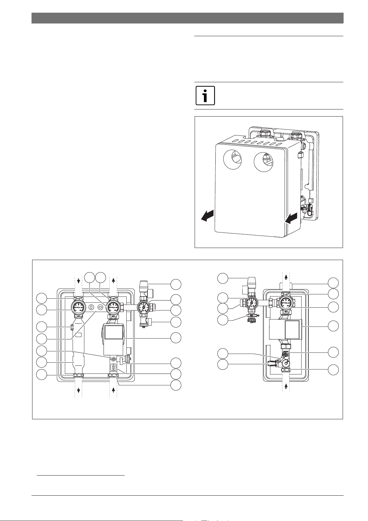
If you wish to open the solar pump station:
▶ Pull the cover (insulation part) forwards.
The illustrations in this manual show the twin-line solar
pump station with external solar controller.
Fig. 1
Fig. 2 Single and twin-line solar pump stations without front insulation parts and without integral controllers and modules
[1] Ball valve with thermometer (red = flow1), blue = return) and
integrated check valve
(position 0° = normal running, 45 ° = check valve bypassed)
[2] Compression fitting
[3] Pressure relief valve
[4] Pressure gauge
1) Not for single-line solar pump stations
[5] Connection for expansion vessel
[6] Drain & fill valve (DFV)
[7] High-efficiency pump (with power cable and sensor cable)
[8] Flow limiter, type A
[9] Flow limiter, type B
[10] Air separator
[11] Control/shut-off valve
[12] Holder for wall mounting
[13] Ventilation
1)
1)
6 720 811 270 (2015/04)AGS10-2, AGS10E-2, AGS20-2, AGS50-2
4 | Information on the solar pump station
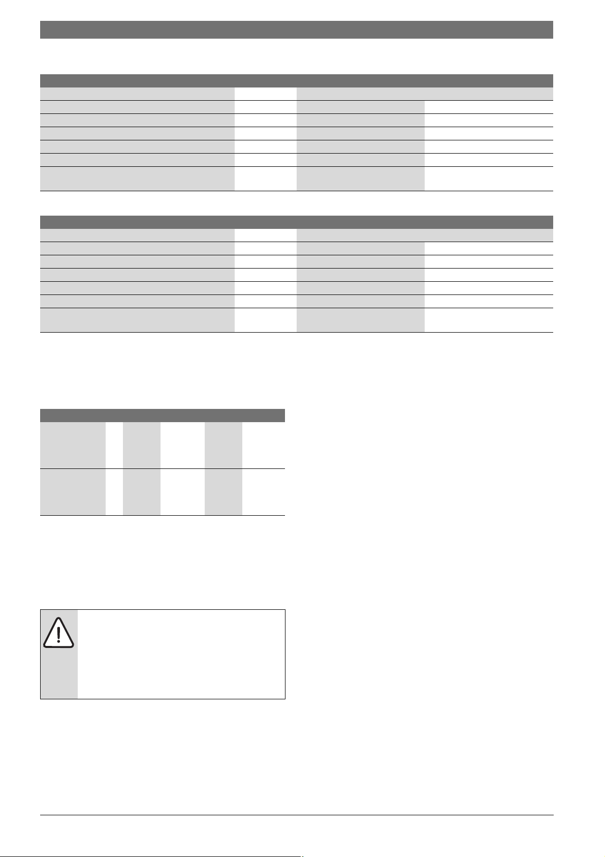
2.1.1 Specifications and variants
AGS10-2 AGS10E-2
Maximum possible temperature °C Flow: 130 / return: 110 (pump)
Safety valve response pressure bar 66
Pressure relief valve – DN 15, ¾ " connection DN 15, ¾ " connection
Mains voltage – 230V AC, 50 - 60 Hz 230V AC, 50 - 60 Hz
Maximum current consumption per pump A 0,4 A / EEI ≤ 0,2 0,4 A / EEI ≤ 0,2
Measurements (height x width x depth) mm 353x284x248 355x185x180
Flow and return connections
mm 15 / 22 15 / 22
(compression fittings)
Table 2 Specifications of AGS10-2 and AGS10E-2
AGS20-2 AGS50-2
Maximum possible temperature °C Flow: 130 / return: 110 (pump)
Safety valve response pressure bar 66
Pressure relief valve – DN 15, ¾ " connection DN 20, 1" connection
Mains voltage – 230V AC, 50 - 60 Hz 230V AC, 50 - 60 Hz
Maximum current consumption per pump A 0,7 A / EEI ≤ 0,2 1,0 A / EEI ≤ 0,23
Measurements (height x width x depth) mm 353x284x248 403x284x248
Flow and return connections
mm 22 28
(compression fittings)
Table 3 Specifications of AGS20-2 and AGS50-2
2.1.2 Energy efficiency
The following product data complies with the requirements of
EU Regulations 811/2013, 812/2013, 813/2013 and 814/2013 as
supplement to the Directive 2010/30/EU.
AGS10-2 AGS10E-2 AGS20 AGS50
Power
W 2.00 2.00 2.00 2.50
consumption
standby (W)
solstandby
Power
W 15 15 22.5 50
consumption full
load (W)
solpump
1)
Table 4
1) 50 % of nominal power input in operation at 72 mbar a nd 50 l/h.
2.1.3 Solar system and additional heat sources
It is often possible to attach multiple heat sources to combi and buffer
cylinders. These heat sources can completely heat the contents of the
cylinder to over 80 °C.
WARNING: Risk of injury from hot fluid leaks.
▶ To avoid blocking the path to the safety equipment,
leave the ball valves of the solar pump station open
during operation.
▶ If required, install an additional item of safety
equipment between the cylinder and the solar pump
station.
AGS10-2, AGS10E-2, AGS20-2, AGS50-26 720 811 270 (2015/04)
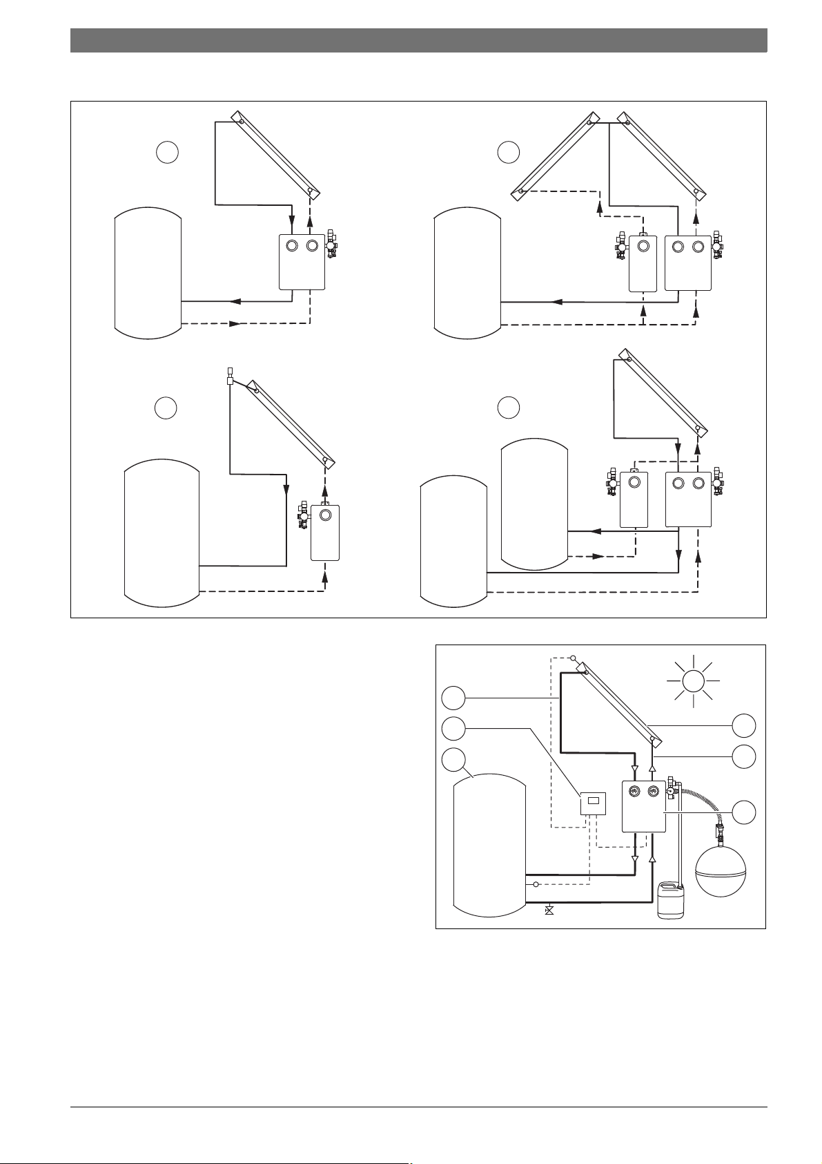
2.1.4 Application examples
1
2
4
7747006489.03-3.ST
3
6720640298-22.2ST
1
4
5
6
2
3
Information on the solar pump station | 5
Fig. 3 Different hydraulic applications
[1] Standard system with dual-circuit solar pump station
[2] Two collector arrays (e.g. east/west) with single and twin-line
solar pump stations
[3] 2-consumer system with single and twin-line solar pump station
[4] Standard system with 1-line solar pumping station and air vent on
roof
2.2 Determined use
▶ Solar pump stations may only be used for the operation of solar
systems in conjunction with suitable controllers.
▶ Solar pump stations may only be installed vertically ( Fig. 3) and
indoors.
The AGS solar pump stations must only be operated with propylene
glycol/water mixtures (heat transfer medium L or LS). The use of any
other heat transfer medium is not permitted.
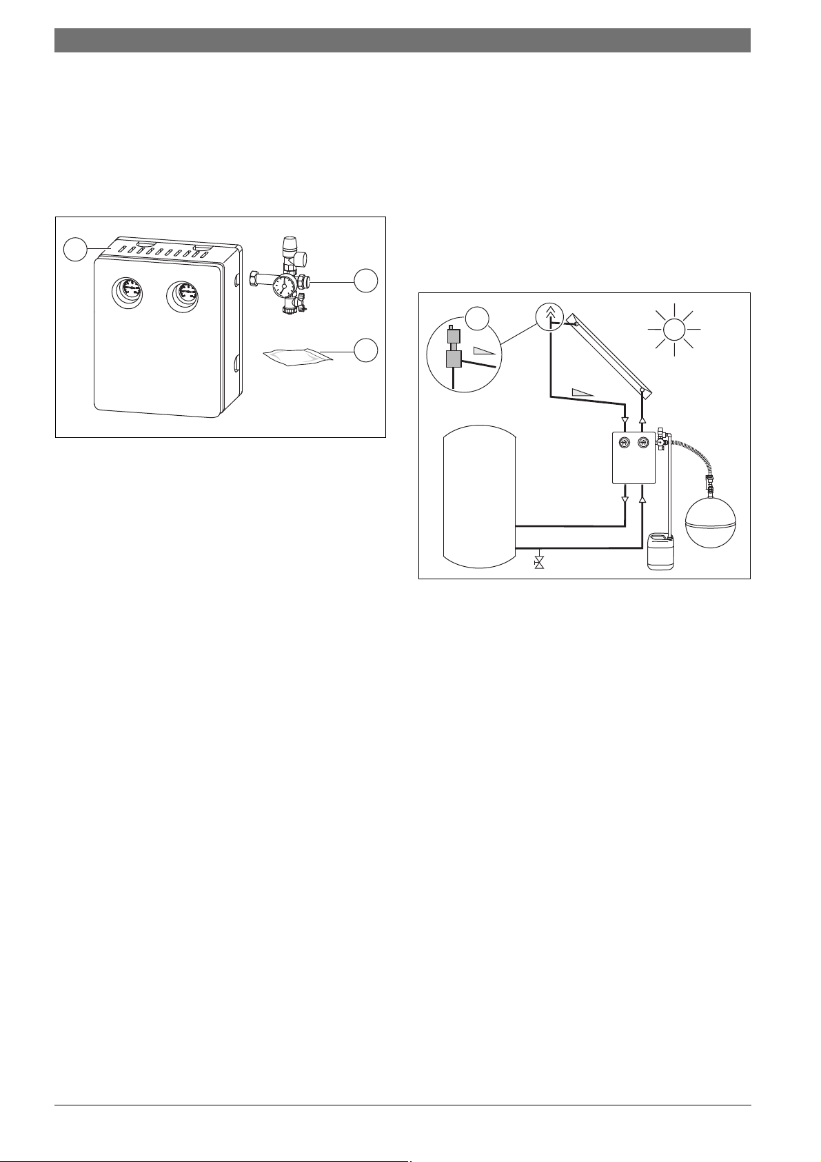
2.3 Components and technical documentation
A solar thermal system is designed to heat domestic hot water (DHW)
and can also provide central heating backup where required. It is made
up of various components.
Fig. 4 Solar system components
[1] Collector with temperature sensor at the top
[2] Pipework (return)
[3] Solar pump station with expansion vessel, temperature and
safety equipment
[4] Solar cylinder
[5] Solar controller
[6] Pipework (flow)
6 720 811 270 (2015/04)AGS10-2, AGS10E-2, AGS20-2, AGS50-2
6 | Information on the solar pump station
6720811275.02-2.ST
1
2
3
6720801165.09-2.ST
1
2.4 EC Declaration of Conformity
Design and operation of this product conform to European Directives
and the supplementary national requirements. Its conformity is
demonstrated by the CE marking. The Declaration of Conformity can be
requested from the manufacturer (see the back cover for the address).
2.5 Scope of Delivery
▶ Check that the delivery is complete and undamaged.
Fig. 5 Solar pump station
[1] Solar pump station (single or twin-line solar pump station with or
without controller)
[2] Safety assembly (pressure relief valve, pressure gauge, fill and
drain valve)
[3] Bag with rawl plugs and screws
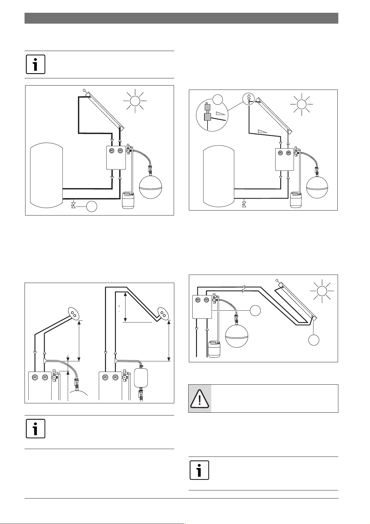
2.7 Air vent valve
Always provide an automatic air vent valve on each row of collectors for
the following systems connected in parallel:
1. System with more than two collector rows.
2. System with AGS50 solar pump station.
Solar-Lifestyle/Solar-Lito flat-plate collectors
The solar system is ventilated through one of the following processes:
1. Pressure filling with solar filling pump ( Chapter 6.2, page 12).
Install additional air vents if necessary, see point 1.– 2. above.
-or-
2. Automatic air vent valve [1] at the highest point of the system
( Chapter 6.2, page 12).
2.6 Other equipment required
In addition to the usual tools, a 13 mm socket with a 150 mm extension
is required for the installation work.
Fig. 6 Position of the automatic air vent valve
Solar-Lux vacuum tube collectors
Only pressure filling and heat transfer medium LS may be used for
ventilation ( Chapter 6.2, page 12). Install additional air vents if
necessary, see point 1.-2. above.
AGS10-2, AGS10E-2, AGS20-2, AGS50-26 720 811 270 (2015/04)
Regulations | 7
3 Regulations
Practical work is subject to currently applicable technical rules.
▶ Observe all standards, guidelines and requirements applicable to the
installation and operation of the system in your country and region.
Modified regulations or supplements are also valid at the time of
installation and must be observed.
Technical regulations applicable in the U.K. for the installation of thermal solar heating systems
• Electrical connection:
– Current IEE wiring regulations
• Connection of solar thermal systems:
– EN 12976: Thermal solar systems and components (factory made
systems)
– BS5918: Latest version: Solar heating systems for domestic hot
water.
• Installation and fittings of hot water heaters:
– BS5546:2006 Specification for installation of hot water supplies
for domestic purposes, using gasfired appliances of rated input not
exceeding 70kW.
– BS6700:2006 Specifications for design, installation testing and
maintenance of services supplying water for domestic use within
buildings and their curtilages.
• Installations should be made in accordance to the relevant MCS Solar
standards if the homeowner is applying for RHI
4 Installing pipework
4.1 General information regarding pipework
NOTICE: System damage through faulty parts.
▶ Only use materials which are resistant to glycol,
pressure and heat (at least up to 150 °C).
▶ Do not use plastic pipes (e.g. polyethylene pipes) or
galvanised pipework.
We recommend carrying out a pipe network analysis to
determine pipework sizing requirements. Basic design
estimates can be made using Tab. 5.
▶ If there are many additional points of resistance
(bends, valves, etc.), you may need to select a pipe
with a larger diameter.
Straight pipe
length
0 to 6 m Ø 15 mm
7 to 10 m Ø 15 mm
11 to 15 m Ø 15 mm
16 to 20 m Ø 22 mm
21 to 25 m Ø 22 mm
Table 5 Pipework sizing
1) For example, solar twin tube 15 (copper)
2) Or solar twin tube DN20 (stainless steel)
Number of collectors
2 to 5 6 to 10 11 to 15 16 to 20
(DN12)
(DN12)
(DN12)
(DN20)
(DN20)
Ø 22mm
1)
(DN20)
Ø 22mm
1)
(DN20)
Ø 22mm
1)
(DN20)
Ø 22mm
2)
(DN20)
Ø 28mm
2)
(DN25)
Ø 22mm
2)
(DN20)
Ø 22mm
(DN20)
Ø 28mm
(DN25)
Ø 28mm
(DN25)
Ø 28mm
(DN25)
Ø 22mm
(DN20)
Ø 28mm
(DN25)
Ø 28mm
(DN25)
Ø 28mm
(DN25)
Ø 35mm
(DN32)
6 720 811 270 (2015/04)AGS10-2, AGS10E-2, AGS20-2, AGS50-2
8 | Installing pipework
1
6720801165.08-2.ST
> 2 m
> 1,5 m
< 2 m
0,2-0,3 m0,2-0,3 m
6720811272.01-1.ST6720811272.01-1.ST
0.2-0.3 m
1.5 m
6720801165.09-2.ST
1
6720640298-61.2ST
2
1
▶ Install a device into the return at the lowest point in the solar system
for draining the solar system (tee with fill and drain valve [1]).
If necessary, allow for the flow of a fill and drain valve as
well ( Chapter 6.2.1, page 13).
Fig. 7
4.2 Laying pipes
Evacuated tube collectors
The minimum pipe length from the solar pump station to the collector
array must be at least 10 m (single length).
The minimum height clearance for the connection of the expansion
vessel to the collector array is 2 m.
Solar-Lifestyle/Solar-Lito flat-plate collectors
To prevent air pockets when using an automatic air vent valve on the
collector array:
▶ Route the pipes from the pump station to the collector/air ve nt [1] on
a rising incline.
▶ If a change of direction downwards is unavoidable, install additional
heat-resistant (150 °C) air vents.
Fig. 9 Position of the automatic air vent valve
In some cases, the solar pump station [1] cannot be installed
underneath the collectors (e.g. in the case of attic installations).
Form a "pipe trough" with the flow in order to prevent overheating in
such systems:
▶ Firstly, route the flow to the height of collector return connection [2].
Then route it to the solar pump station.
Fig. 8 Distance to the collector array (Solar-Lux)
If the minimum pipe length or the minimum height
distance cannot be maintained:
▶ Form a "pipe trough" at least 1.5 m high with the flow
and return lines on the collector array ( Fig. 8).
Fig. 10
Connecting pipework
NOTICE: Risk of damage to the collector through heat
created by brazing.
▶ Do not solder close to evacuated tube collectors.
▶ Copper pipes must only be soldered with brazing solder i.e. no low
temperature soldering.
-or-
▶ Use glycol and heat-resistant (150 °C) compression fittings or push-
fit fittings.
If threaded pipe connections are caulked with hemp:
▶ Use a thread sealing compound resistant to
temperatures up to 150 °C (e.g. NeoFermit
universal).
AGS10-2, AGS10E-2, AGS20-2, AGS50-26 720 811 270 (2015/04)
Installing the solar pump station | 9
UV
> 150 °C
> 150 °C
6720801165.10-1.ST
7747006489.07.3 ST7747006489.07.3 ST
4
1
10
13
150 mm
2
60 mm
3
6720801165.11-2.ST
Earthing pipes
Arrange for work to be performed by a competent person.
▶ One earthing clamp must be fitted to both the flow pipe and the return
pipe (at any position).
▶ Connect the earthing clamps to the building's equipotential bonding
strip by means of a standard PVC-sheathed bonding cable (cable to be
sized in accordance with BS7671).
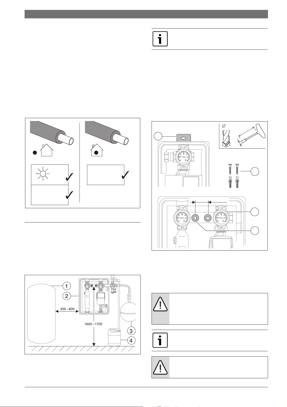
Insulating pipework
▶ Thermally insulate the pipework in the entire solar circuit in
accordance with regulations and best practice.
▶ Insulate outdoor piping with material which is both resistant to UV
light and high temperatures (up to 150 °C).
▶ Insulate indoor piping with material which is resistant to high
temperatures (up to 150 °C).
▶ Protect the insulation against damage from animals if required.
Observe minimum clearances from the solar pump
station to the collector array of the vacuum tube
collectors ( Chapter 4.2, page 8)
5.2 Mounting the solar pump station
Use a socket (13 mm) with a 150 mm extension to screw in the screws.
With shorter extensions, the handles and temperature gauges [3] can be
pulled forwards and removed for easier access to the screws.
Single-line solar pump station
▶ Drill hole and fix solar pump station using rawl plug and screw
supplied [1, 2].
Twin-line solar pump station
▶ Drill holes spaced 60 mm apart and fix solar pump station using rawl
plugs and screws supplied [4, 2].
Fig. 11 Minimum requirements of the insulation
5 Installing the solar pump station
5.1 Layout of the installation space
To make it easier to connect the temperature sensors:
▶ Install the solar pump station [2] as close as possible to the solar
cylinder [1].
▶ Allow enough room for a solar expansion vessel [3] and holding
container [4].
Fig. 13 Mounting the station
[1] Mounting for single-line solar pumping station
[2] Rawl plugs and screws supplied
[3] Thermometer
[4] Mounting for twin-line solar pump station
5.3 Electrical connection
DANGER: Danger to life through electric shock!
▶ Before carrying out work on electrical components,
isolate them from the power supply (230 V AC) (fuse,
circuit breaker) and secure against unintentional
reconnection.
Electrical connections must only be completed by
appropriately qualified engineers subject to local and
national regulations.
Fig. 12 Recommended positioning (measurements in mm)
[1] Solar cylinder
[2] Solar station
[3] Expansion vessel
[4] Drip pan
NOTICE: Damage through pump running dry!
▶ Do not run the pump until the pipework system has
been filled.
6 720 811 270 (2015/04)AGS10-2, AGS10E-2, AGS20-2, AGS50-2
 Loading...