


|
|
|
|
|
|
NODE 1.1 & NODE 2.1 |
|
|
Complete Instructions. |
|
|
|
About This Manual |
|
|
|
|
|
|
This is the complete manual for your NODE computer. It explains how |
|
|
to install your NODE computer and complete the setup (programming). |
|
|
It includes riding safety. It also shows how to access the features of your |
|
|
NODE computer and to view and record your ride data. If you need |
|
|
additional information, visit your Bontrager dealer or visit us online |
|
|
at www.bontrager.com. |
|
|
|
|
|
|
ENGLISH
Contents |
|
SAFETY....................................................................... |
1 |
BASIC INFORMATION |
|
Display (screen) ........................................................................ |
2 |
Function list................................................................................ |
3 |
Buttons ....................................................................................... |
4 |
Memory ...................................................................................... |
4 |
Modes......................................................................................... |
5 |
INSTALLATION |
|
Process Overview ...................................................................... |
6 |
Attaching the Computer ............................................................ |
7 |
Setup (Initial Programming)....................................................... |
8 |
Basic Setup ................................................................................ |
9 |
STARTING A RIDE |
|
Main Ride Functions................................................................ |
14 |
Secondary display ................................................................... |
15 |
RECAP (Review Trip Data) |
|
Switch to RECAP mode........................................................... |
23 |
See Recap (Trip data) .............................................................. |
24 |
MANAGE (Optional Programming) |
|
Switch to Manage mode.......................................................... |
25 |
Bike Selection .......................................................................... |
26 |
Wheel Size................................................................................ |
27 |
Altitude ..................................................................................... |
30 |
Cadence ................................................................................... |
31 |
Power ....................................................................................... |
32 |
Heart Rate and Calories .......................................................... |
34 |
Temperature ............................................................................. |
40 |
Dual View.................................................................................. |
42 |
Clock......................................................................................... |
45 |
Distance ................................................................................... |
47 |
Language.................................................................................. |
49 |
BATTERY INFORMATION ....................................... |
50 |
RESET....................................................................... |
51 |
TROUBLESHOOTING .............................................. |
52 |
Screen Terms
The following abbreviations appear on the screen of the Node computer.
Abbreviation |
Meaning |
ALT |
Altitude |
AVG |
Average |
BIKE |
Bicycles, including bike1 and bike 2 |
CAD |
Cadence |
CAL |
Calorie |
CLOCK |
Clock |
CUR |
Current, or now |
DIST |
Distance |
F |
Female |
GRADE |
Grade |
HR |
Heart Rate |
KG |
Kilogram |
LB |
Pound |
M |
Male |
MAX |
Maximum |
MIN |
Minimum |
ODO |
Odometer |
OFF |
Off |
ON |
On |
PWR |
Power |
TEMP |
Temperature |
TIME |
Time |
i

SAFETY
When riding your bicycle, do not stare at the computer for a long time (Figure 1). If you do not watch the road, you could hit an obstacle, which might cause you to lose control and fall.
Figure 1. Do Not Stare at Computer for Long Periods of Time.
1

BASIC INFORMATION
This section describes the NODE display, the terms used in this manual, and the working modes. This is background information to help you understand the other sections of the manual. However, you will not see any of the screen elements until you have installed the computer.
Display (screen)
There are four regions of data on the NODE screen:
Computer status
The uppermost section of the NODE screen shows the status of connected sensors, mode, bike selection, and battery level.
Time and Ride Clock
The second section of the NODE screen shows the time of day (either 12-hour or 24-hour) and the Ride Clock, which shows the time the computer has been running on the current trip.
Speed
The NODE always shows Speed as the biggest numbers in the middle of the display.
Active Sensor Indicators
–Speed
–Cadence
–Power –Heart Rate
Clock
Speed Function Selection
–Current
–Average
–Maximum
|
Bike Selection |
Recap Mode |
–Bike 1 |
|
–Bike 2 |
|
Battery |
|
Ride Clock |
|
Speed |
|
(Primary Display) |
|
Mode |
|
(Secondary Display) |
Mode Indicators
2
2

Secondary display
The lower part of the display shows the secondary functions.
When set to Dual View, your computer shows two secondary functions at the same time. See the section ‘Setting the Dual View’ in the Manage section.
Function list
The NODE 1.1 and NODE 2.1 have different function menus.
 NODE 1.1
  NODE 2.1
Distance |
X |
X |
Dual View |
X |
X |
|
||
Cadence |
X |
X |
|
||
Heart rate |
X |
X |
|
||
Power |
X |
X |
|
||
Grade |
|
X |
|
|
|
Altitude |
|
X |
|
|
|
Temperature |
|
X |
|
|
You can switch most of the sensors to Off or On. If a sensor is switched to Off, its function does not appear when you browse functions.
Active Sensor Indicators
–Speed
–Cadence
–Power –Heart Rate
Clock
Speed Function Selection
–Current
–Average
–Maximum
|
Bike Selection |
Recap Mode |
–Bike 1 |
|
–Bike 2 |
|
Battery |
|
Ride Clock |
|
Speed |
|
(Primary Display) |
|
Mode |
|
(Secondary Display) |
Mode Indicators
3
3
Buttons
The NODE has four buttons (Figure 7). The actions for buttons are described in the table below. For simplicity, these are the abbreviations of button names:
T is Top
B is Bottom s1 is Side 1 s2 is Side 2
 Browse
Hold
 Press
Press
Press and repeat to switch through a list of values or screen elements.
Press a button continuously for about three seconds.
 Push a button once, briefly.
Memory
The NODE has a Trip memory and a Total (accumulated) memory.
Trip data
•Cadence AVG and MAX
•Distance
•Heart Rate AVG, MIN, and MAX; plus Zones 1 through 5
•Power AVG, MIN, and MAX
• SpeedAVG and MAX |
|
• Altitude (ALT), +, –, and GradeAVG(%) |
and MAX |
Erasing trip data: Trip Restart
The Trip data can be erased (set to 0) before each ride (Figure 8): hold s1 for three seconds. Resetting the Trip memory does not affect the Total memory.
Accumulated data (Total memory)
•Total distance
•Total altitude gain
Erasing total memory: Reset
You can set all values in the memory to0 (zero) and erase all settings. See page50.
T
s1
s2
B
Figure 7. Names of Buttons.
s1 (3 seconds)
Figure 8. Erase Trip Data.
4
4
Modes
The NODE computer has five modes:
Setup
This mode allows you to ‘program’ the computer, setting your preferences for language, distance units, time, and odometer.
Ride
Use the Ride mode (Figure 9) when riding. It shows displays of the information gathered by the computer. This information can be the current data: your current speed, the current temperature, or data from other functions. For some functions
the NODE can display your average, total, or minimum/maximum data. You can
learn more about each of these functions in the section that covers functions.
Figure 9. Ride Mode.
Recap
When you have finished a ride or just want to see your data, you can view the computed data in the Recap mode (Figure 10).
Manage
Recap
This mode allows you to revise the Setup or perform advanced settings.
Sleep (Standby)
If the sensors do not send a signal to the NODE for 20 minutes, the computer goes into Standby to conserve battery power. In Standby, the screen will display two dashes (— —). After an additional 10 minutes, the NODE switches to Off.
NOTE: To extend battery life during long periods of non-use, remove the computer from its computer base. This deactivates the Auto Start feature.
There are two methods for waking the computer:
• Press any button
• Autostart: spin the wheel to make the wheel sensorsignal send a
Figure 10. Recap Mode.
5
5
INSTALLATION
Getting your Node up and running is easy and takes only about 10 minutes.
Process Overview
It will help you through the process if you take the time to completely read the installation section before you start. For example, you cannot complete the setup process (#3 below) if the sensor cannot read the magnet in the wheel (#1).
Here are the steps in the process (explained more fully in the following pages):
1.Install the speed sensor and wheel magnet (see the instructions packaged with the sensor). Install optional accessory sensors.
2.Attach the computer to the handlebar or stem.
3.Setup your preferences for time, miles, etc.
4.“Pair” the computer (make the computer recognize and remember the radio signal from the sensor).
Sensors
Your NODE is not packaged with sensors. You can purchase sensors for the NODE from your Bontrager dealer. For installation instructions for a sensor, see those packaged with the sensor.
The NODE can read up to four signals or sensors:
•Speed
•Cadence
•Heart rate
•Power
•Combo (speed and cadence)
You can add sensors at any time. However, additional setup work is required each time you add a sensor.
Tools Required
•Screwdriver, small phillips type
•Coin
Parts List
C
A
 F
F
|
I |
|
J |
|
H |
|
G |
E |
B |
D
Figure 11. Parts Included with Your Node Computer.
A.Handlebar clamp
B. Rubber pad
C.Brackets
D.Battery
E.Rubber shim
F.Zip ties
G. Screw & washer
H. Battery cover
I.Rubber o-ring
J.Heart rate strap ( NODE 2.1 only)
6
6

Attaching the Computer
You can choose to attach the computer to the handlebar or the stem.
On the handlebar, consider your preference for left and right, and your access to the buttons on the computer. On the stem, the computer is in the center.
Handlebars are generally round with only one or two sizes, while stems come in many shapes and sizes. Because stems have so much variation, one or two clamp designs cannot accommodate them all. Therefore, mounting to the stem requires zipties.
To Attach to the Handlebar
1.Determine the diameter of your handlebar (25.4 mm, 26.0 mm, or 31.8 mm).
2.Insert the correct handlebar clamp into the computer base (Figure 12).
3.Slide the head of the handlebar clamp to the end of the slot in the computer base.
4.Insert the rubber pad with logo into the back of the computer base (Figure 13).
5.With the screw hole toward the back of the bike, wrap the handlebar clamp around the handlebar.
6.Insert the screw and tighten, just until the computer base no longer rotates on the handlebar (Figure 14). Do not overtighten.
7.Slide the computer into the computer base (Figure 15).
To Attach to the Stem
1.Insert the rubber pad with logo into the back of the computer base (Figure 16).
2.Position the computer base on the stem with the screw hole toward the back of the bike (Figure 17).
3.Secure the computer base to the stem using zip-ties.
4.Slide the computer into the computer base (Figure 15).
Figure 12. Clasp in Back of |
Figure 13. Pad Inserted in Computer Base. |
Computer Base. |
|
Figure 14. Tighten Screw. |
Figure 15. Slide Computer into |
|
Computer Base. |
Figure 16. Pad Inserted in |
Figure 17. Base on Stem. |
Computer Base. |
|
7
7
Setup (Initial Programming)
The NODE is shipped with the battery outside the computer so that the battery is fresh. When you install the battery, your NODE will automatically proceed through this Setup, including the Pairing process and Connecting procedures. The automatic Setup also happens when you replace the battery or perform the Reset procedure. Read this entire page before proceeding.
Before you start Setup
Before starting the Setup, complete the installation of the computer bracket, sensor, and magnet (for a sensor, see the installation instructions that are packaged with the sensor). Install the battery andNODEplacewithinthe 5 feet
(1.5 m) of the sensor, and be ready to activate the sensor as explained in the next section.
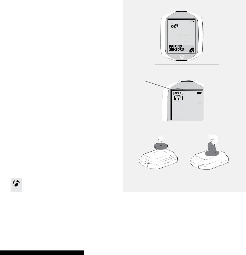
Pairing Sensors
“Pairing” is a process used by the computer to identify the signal from a sensor (Figure 18). This process happens at the end of the initial setup. When a sensor is paired, its icon appears on the screen (Figure 19).
For the computer to find and pair to the sensor, the sensor must send a signal. The speed sensor only sends a signal when the wheel rotates.
Installing the Battery
1.Insert the supplied battery with the ‘+’ facing up or out.
2.Attach the battery cover. Turn the cover clockwise with a coin.
Figure 18. Pairing onto Radio Signals to Identify Sensors.
Sensor icons
Figure 19. Icons Indicate Sensors that are Connected.
1. |
2. |
8
8
Basic Setup
In this procedure, you will set your preference for a function, then save those preferences. When you save one function, the setup program proceeds to the next function.
1.Wake the computer: install the battery, push any button, or make the speed sensor send a signal.
2.To change the language (chooseDeutsch, English, Espanol,orFrancais),
press T or B .
To save the Language and proceed to the Clock (clock type) function, press s1 .
3. The clock shows the time of day. To change the type of clock s2 .
To save the Clock and proceed to the Set Clock (set time) function, press s1 .
4. To change the hours, press T or B .
To set the hours and proceed to change the minutes, press s2 .
T T
s1 |
s1 |
|
|
|
or |
s2 |
|
B |
B |
1. |
2. |
s1
s2 |
3.
T
or
s2 |
B
4.
9
9

5. To the change the minutes, press T or B .
If desired, you can go back to the hours in the previous step by pressing s 2 .
To save the Set Clock (time) and proceed to the Wheel (wheel size) function, press s1 .
6.To change the wheel size (choose from the Wheel size menu on the right), press T or B .
To set a custom wheel size, see page 27.
To save the Wheel and proceed to the Distance (units) function, press s1 .
7. To change units (chooseKMorMILES), press |
s2 . |
To save the Units and proceed to the Odometer function, press s1 .
T
s1
or
B
5.
T
s1
or
Wheel size menu
700 x 20 |
|
|
700 x 23 |
B |
|
700 x 25 |
||
|
||
700 x 28 |
6. |
700 x 32 |
|
|
700 x 35 |
|
|
700 x 38 |
|
|
26 x 1.5 |
|
|
26 x 1.9 |
|
|
26 x 2.0 |
|
|
26 x 2.1 |
s1 |
|
26 x 2.2 |
||
|
||
Custom |
|
s2 |
7.
10
10

8. The odometer shows your accumulated distance.
You can skip this step and leave the value at 00000 by pressing s 1 , and then go to step 10.
To change the highlighted number, press T or B .
To select a value and proceed to the next digit, press s2 .
9. Repeat for each of the other four digits:
To change the highlighted number, press T or B .
To select a value and proceed to the next digit, press s2 .
If desired, you can go back to the first digit (and then the other digits) by pressing s 2 .
To save the Odometer and proceed to the Pairing Process, press s1 .
10. After saving the odometer settings, the Node goes into the Pairing Process. For the Node to Pair to a sensor signal, you must activate the sensor so that it sends a signal:
•Speed: spin the wheel
•Cadence: rotate the crankarm
•Heart rate: wear the chest strap
•Power: rotate the crankarm (or, for a hub sensor, turn the wheel)
The next page explains the display during pairing.
11.When the screen shows “Setup Complete,” press s1 to save all your settings and switch to the Ride mode.
T
or
s2 |
B
8.
T


 s1 or
s1 or 


s2 |
B
9.
s1 |
10.
11
11

The display during Pairing
During the Pairing process, the display shows PAIRING SENSORS and the receiving icon flashes in the lower right corner (Figure 20). When the computer finds the signal and pairs to it, the icon for the sensor flashes three times and it is then added to the display. Figure 21 shows the speed sensor is paired. The Pairing process continues for one minute, or until you press any button to end it. The display then shows SENSORS FOUND and a number, which is the number of sensors to which it has paired.
When the pairing process is finished, the display shows SETUP COMPLETE (Figure 22). Press the upper side button, s1, and then the computer shows the DIST display and is in Ride Mode, ready for you to ride (Figure 23).
Figure 20. Pairing Sensors. |
|
Figure 21. Sensors Found. |
|
Figure 22. Setup Complete. |
When the NODE changes to Ride mode and shows the Speed display, it is ready for use.
If the speed icon does not appear after the Pairing process, do one of the following:
• Perform the Force Pair procedure
• Press the Reset button to start over (erase all setup, see the complete
NODE manual) |
Figure 23. Ride Mode. |
• See the Troubleshooting section. |
|
Force Pair
If the NODE fails to Pair with a sensor, or you add a sensor after the initial setup, |
|
you can force the Pairing process: |
s1 |
1. In Ride mode, hold s1 and s2 for three seconds and then make each sensor |
|
send a signal. |
s2 |
|
(3 seconds)
(3 seconds)
1.
12
12
STARTING A RIDE
This section explains how to start a new ride. To start a ride, you must connect the sensor and then either continue your previous ride or start a new ride.
Connecting the Sensor
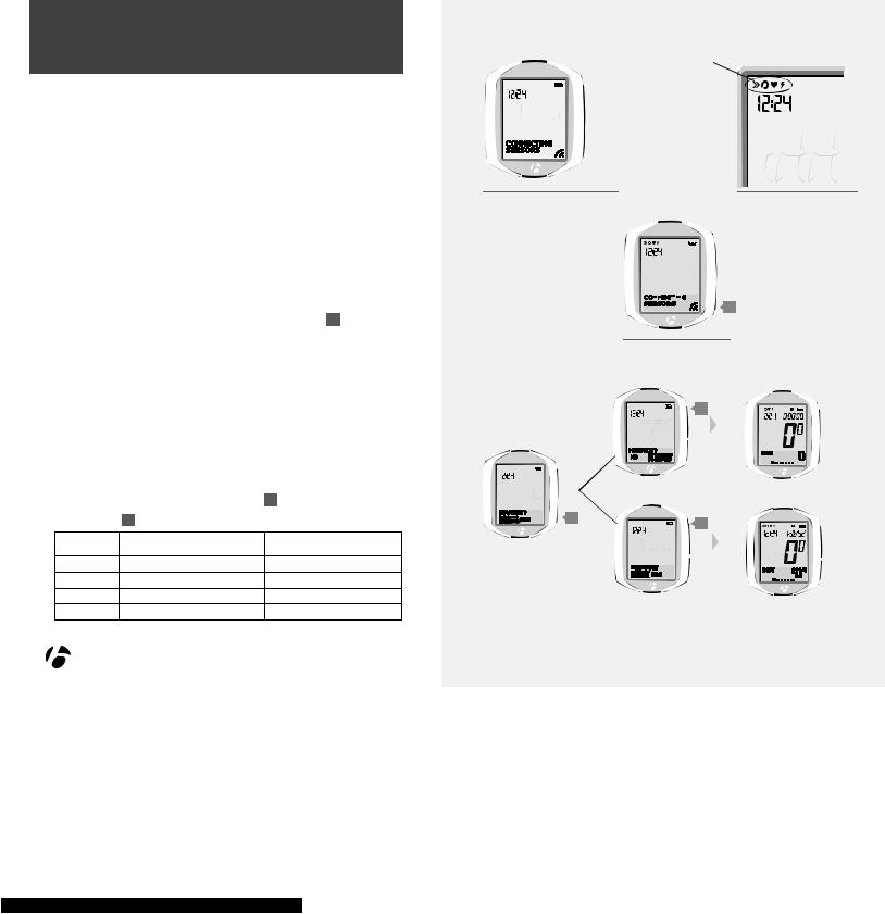
Each time you wake the NODE or switch it to On, it automatically tries to communicate with the sensor. This is called “connecting.” For the NODE to connect to the speed sensor, the wheel must turn.
The display during Connecting
During the Connecting process, the display shows CONNECTING SENSORS and the lower right corner of the display flashes the ‘receiving’ icon (Figure 24). This process can take as long as a minute to complete. The NODE shows the connected sensor in the upper left corner of the display (Figure 25).
After connecting, the display shows NEW RIDE?
Force Connect
If your NODE did not connect correctly, you can “Force Connect,” making the NODE repeat the connecting procedure. In Ride mode, hold s2 for three seconds and then make the sensor send a signal (Figure 26).
NEW RIDE?
1. |
To change the value (chooseYESorNO), press |
s2 . |
||
2. |
To select, press s1 . |
|
||
|
|
|
YES |
NO |
|
Trip data |
Erased |
Saved |
|
|
Trip Clock |
0:00:00 |
Starts from previous time |
|
|
Backlight |
Switches to On for 5 seconds |
|
|
|
|
|
Switches to RIDE mode |
Switches to RIDE mode |
|
|
|
|
|
|
|
|
|
|
Sensor icons
|
|
|
|
|
|
|
|
|
|
|
|
|
|
|
|
|
|
|
|
|
|
|
|
|
|
|
|
|
|
|
|
|
|
|
|
|
|
|
|
Figure 24. Connecting to Sensors. |
|
|
|
|
Figure 25. Connected Sensors. |
||||
|
|
|
|
|
|
|
|
|
|
|
|
|
|
|
|
|
|
|
|
s2 (3 seconds)
Figure 26. Force Connect.
s1
s2 |
s1 |
|
1. |
2. |
13
13
Main Ride Functions
This section explains how to access and see the displays of the NODE computer. The information is arranged in the order in which the displays appear as you browse through the functions.
To see these functions, you must first connect the sensors as discussed in Starting a Rideon page 13. If a sensor is not connected, that function will be skipped. In other words, if the heart rate sensor is not connected, the screen for heart rate will not appear after cadence. Instead you will see the screen for the function of the next connected sensor.
Note: The NODE 2.1 has additional functions not available on the NODE 1.1. When viewing the NODE 1.1 secondary display, the browse sequence goes from its last connected sensor function (Speed, Cadence, Heart Rate, or Power) to Distance.
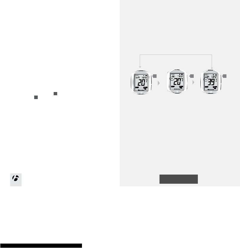
Speed
In Ride mode, the computer always shows Speed as the biggest numbers in the middle of the display. Speed is a measurement of how fast your bike is moving.
1.To switch from current speed (no letters) to average speed (AVG) and then to maximum speed (MAX), browse s1 .
The lower button, s2 , switches the functions in the lower, secondary display. The
secondary display is explained on the next page. |
1. |
s1 |
s1 |
s1 |
RIDE Mode
14
14
14
Secondary display |
|
|
|
|
|
|
The lower part of the display (Figure 28) shows the secondary functions. |
|
|
|
|
||
If a sensor is switched to Off, the computer will not show the display for the matching |
|
|
|
|
||
function. Some secondary functions are only available on the NODE 2.1. |
|
|
|
|
||
Function |
NODE 1.1 |
NODE 2.1 |
Figure 28. Secondary Display |
|
|
|
|
|
|
|
|
|
|
Distance |
X |
X |
|
|
|
|
Dual View |
X |
X |
|
|
|
|
Cadence |
X |
X |
|
|
|
|
Heart rate |
X |
X |
|
|
|
|
Power |
X |
X |
|
|
|
|
Grade |
|
X |
s2 |
s2 |
s2 |
s2 |
|
|
|
|
|
||
Altitude |
|
X |
|
|
|
|
Temperature |
|
X |
|
|
|
|
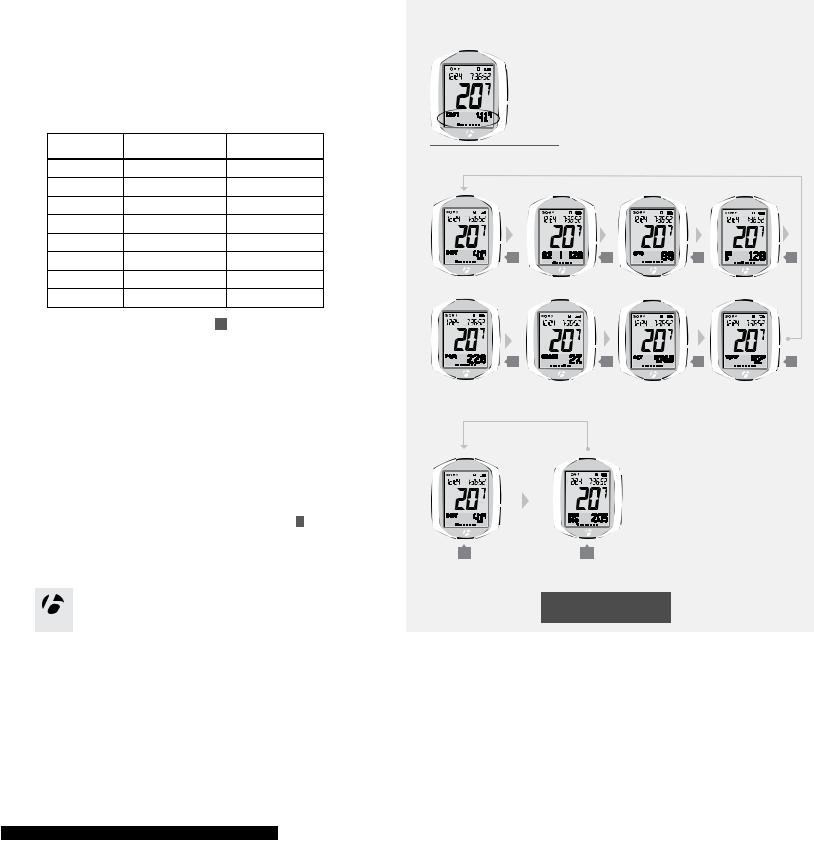
1. To see each secondary function, browse s2 . |
|
|
|
|
|
|
The following sections explain each function and show its features. |
|
|
|
|
||
|
|
|
s2 |
s2 |
s2 |
s2 |
1.
DIST
Distance
As you ride, the NODE measures how far you have gone, shown as Distance. This is the Trip distance, the distance you have ridden during this ride.
1. To see your total accumulated distance (DIST ODO), browse B .
B B
1.
RIDE Mode
15
15
15
 Loading...