


231793

HUB INSTRUCTIONS
PART NUMBER 231793 SERVICE MANUAL 2003

HUB INSTRUCTIONS
STANDARD
Front Hubs
Loose ball . . . . . . . . . . . . . . . . . . . . . . . . . . . . . . . . .2-3
Loose ball, semi-cartridge; Formula FCM . . . . . . .4-5
Cartridge bearing, alloy axle . . . . . . . . . . . . . . . . .6-7
Cartridge bearing, threaded alloy axle . . . . . . . . . .8-9
Rear hubs
Freehub body information (non-DT Swiss) . . . . . . . 11
Loose ball . . . . . . . . . . . . . . . . . . . . . . . . . . . . . . .12-13
Loose ball, double sealed (Formula FCM) . . . . . .14-15
Cartridge bearing . . . . . . . . . . . . . . . . . . . . . . . . .16-17
DT-SWISS
Comp series hubs
Introduction . . . . . . . . . . . . . . . . . . . . . . . . . . . . . . . 19
Comp front . . . . . . . . . . . . . . . . . . . . . . . . . . . . . .20-21
Comp rear . . . . . . . . . . . . . . . . . . . . . . . . . . . . . . .22-24
Pro series hubs
Introduction . . . . . . . . . . . . . . . . . . . . . . . . . . . . . . . 25
Pro front . . . . . . . . . . . . . . . . . . . . . . . . . . . . . . . .26-27
Pro rear . . . . . . . . . . . . . . . . . . . . . . . . . . . . . . . . .28-31
Please note: Many sections of this manual must be
read in their entirety before performing procedures.
In some cases, revised or updated information may
be available on the Bontrager wheelworks website at
www.bontrager.com.
If you cannot find the information you need to service
Bontrager wheels, please contact a technical service
representative.
Copyright Trek Bicycle Corporation 2002
All rights reserved
2003 Bontrager Service Manual
1
Front hubs- Loose ball
Bontrager Superstock, Superstock Disc, Select ATB, Select ATB Disc, Select Road, and Select Hybrid front wheels;
plus Bontrager Comp II front hub
Recommended tools
13mm cone wrench
17mm cone wrench
Small slot screwdriver
Hammer (soft faced)
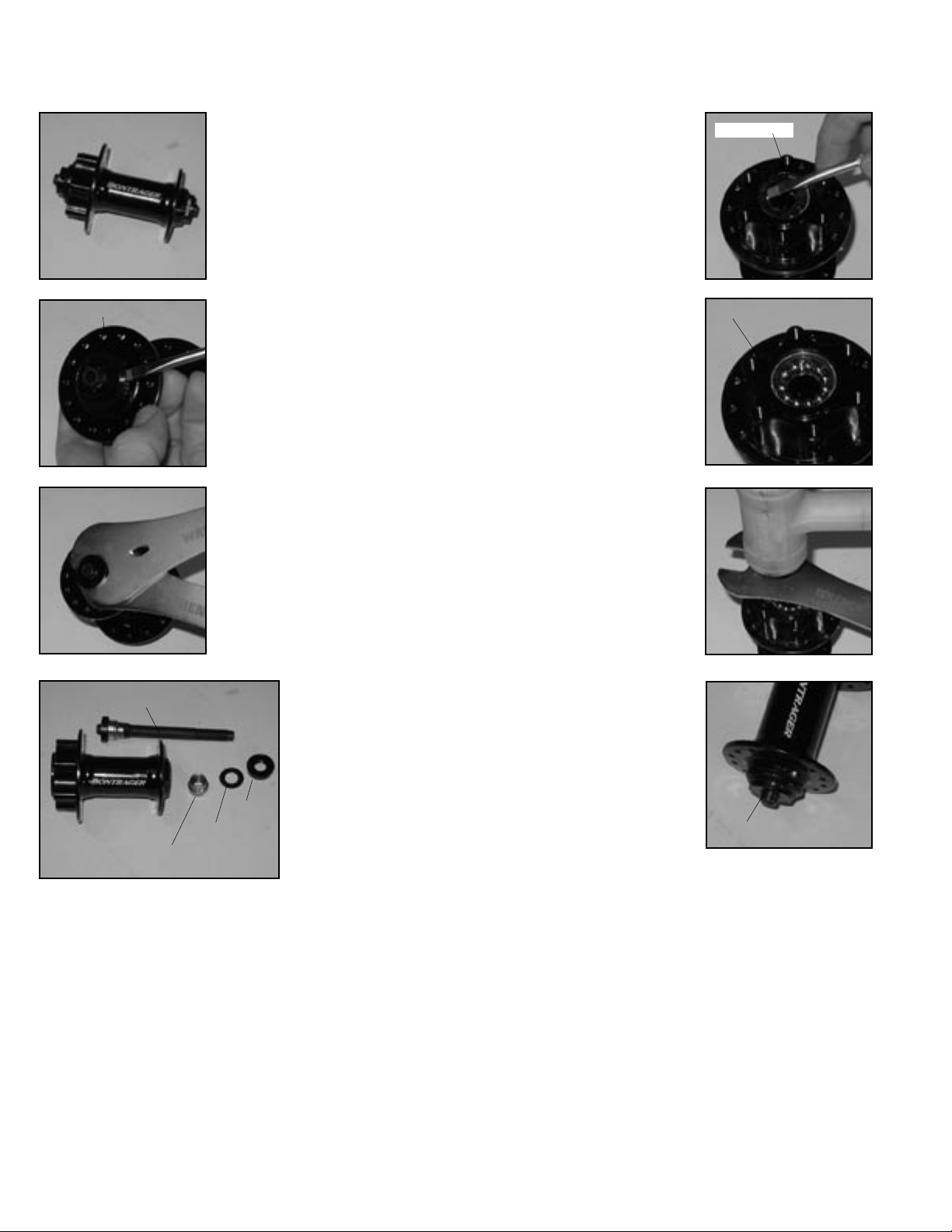
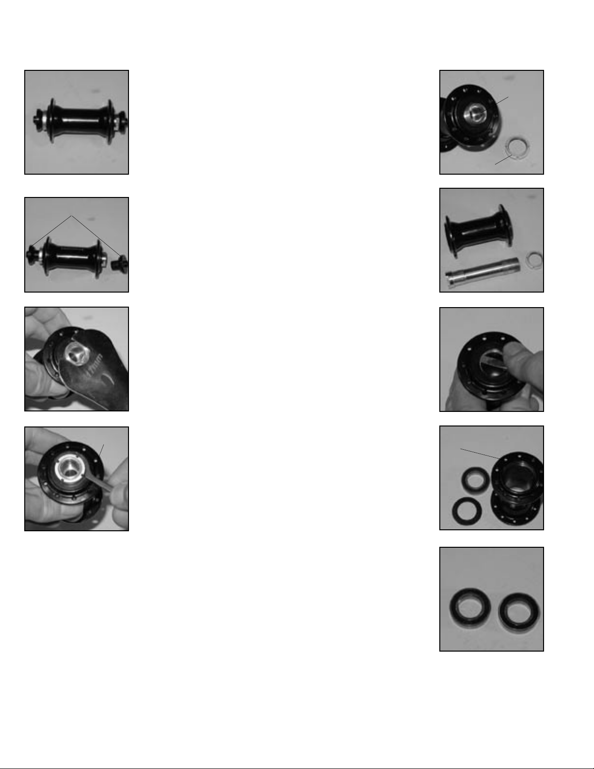
DISASSEMBLY
Hub parts and names are referenced on next page.
Remove the axle
Fig. 1A
External seal
Fig. 2A
Fig. 3A
Axle
Ball cone
Fig. 4A
Clean and inspect the parts
1. Use solvent to completely remove all old grease and
debris from the hub, axle, and axle parts.
2. Inspect the bearing running surfaces of both the
ball cones and the ball cups (inside the hub). Replace any
cones. If the cups are worn, replace the hub shell.
1. Remove external seals
(Fig. 2A) with a screwdriver. Be
careful not to tear or mar the
rubber.
2. On one side (either) of the
hub place a 13mm cone wrench
on the ball cone. Place a 17mm
cone wrench on the end nut (Fig.
3A). Loosen the end nut.
3. Remove the end nut,
washer, and ball cone from the
axle (Fig. 4A).
4. Slide the axle, with the
other end nut, washer, and ball
cone still attached, out of the
hub (Fig. 4A).
5. Gently insert a thin
screwdriver blade under the
shell shield (Fig. 5A) and lift to
remove the shield from the hub.
Pry off the shell shields from
both sides of the hub.
6. If inspection
shows it necessary,
remove the other end
nut and ball cone.
End nut
Washer
ASSEMBLY
Shell shield
1. Place eleven 3/16” balls in
the ball cup on one side of the hub.
2. Place the shell shield, with
its sharp edges facing out (Fig.
6A), into the hub. The shell shield
is a press fit, so must be tapped
lightly to fully seat. Lay a cone
wrench over the shell shield and
tap the wrench with a hammer
(Fig. 7A) to protect the shield
and ensure that it is flush with
Bearings in bearing cup
the shell.
3. Repeat Assembly steps 1-2
for the other side of the hub.
4. Tighten the end nut
against the ball cone on the axle.
Hold the ball cone with a 13mm
cone wrench on the axle flats
while turning the end nut with a
17mm cone wrench.
5. Insert the axle through the
hub from either side.
6. Thread the ball cone, washer, and end nut onto the axle in
that order. The serrated surface
of the end nut faces out.
7. Hold the ball cone with a
13mm cone wrench and tighten
the end nut with a 17mm cone
wrench.
8. Check the bearing adjustment by turning the axle with
your fingers. The axle should
spin smoothly without binding or
feeling gritty. There should be no
lateral play of the axle in the hub.
Readjust the hub as necessary,
and re-lock the end nut.
9. Install the external seals,
and apply grease where the seals
Seal not seated
contact the hub shell and axle
parts. Make sure the seals properly seal against both the end nut and the hub shell. There
should be a smooth transition from seal to sealing surface.
An improperly installed seal (Fig. 8A) will allow rapid contamination of the bearings.
After completing assembly of the hub, check its function by spinning the axle with your fingers. It
should rotate freely without irregular friction. A small amount of lateral play is acceptable if the play is
eliminated when the wheel is installed with the quick release properly closed.
Fig. 5A
Fig. 6A
Fig. 7A
Fig. 8A
Lubricate bearings and threads
1. Lubricate the threads on the axle with Wrench
Force™ synthetic grease, or a similar product.
2. Place a bead of grease all the way around each ball
cup, sufficient to hold the balls.
2
2003 Bontrager Service Manual
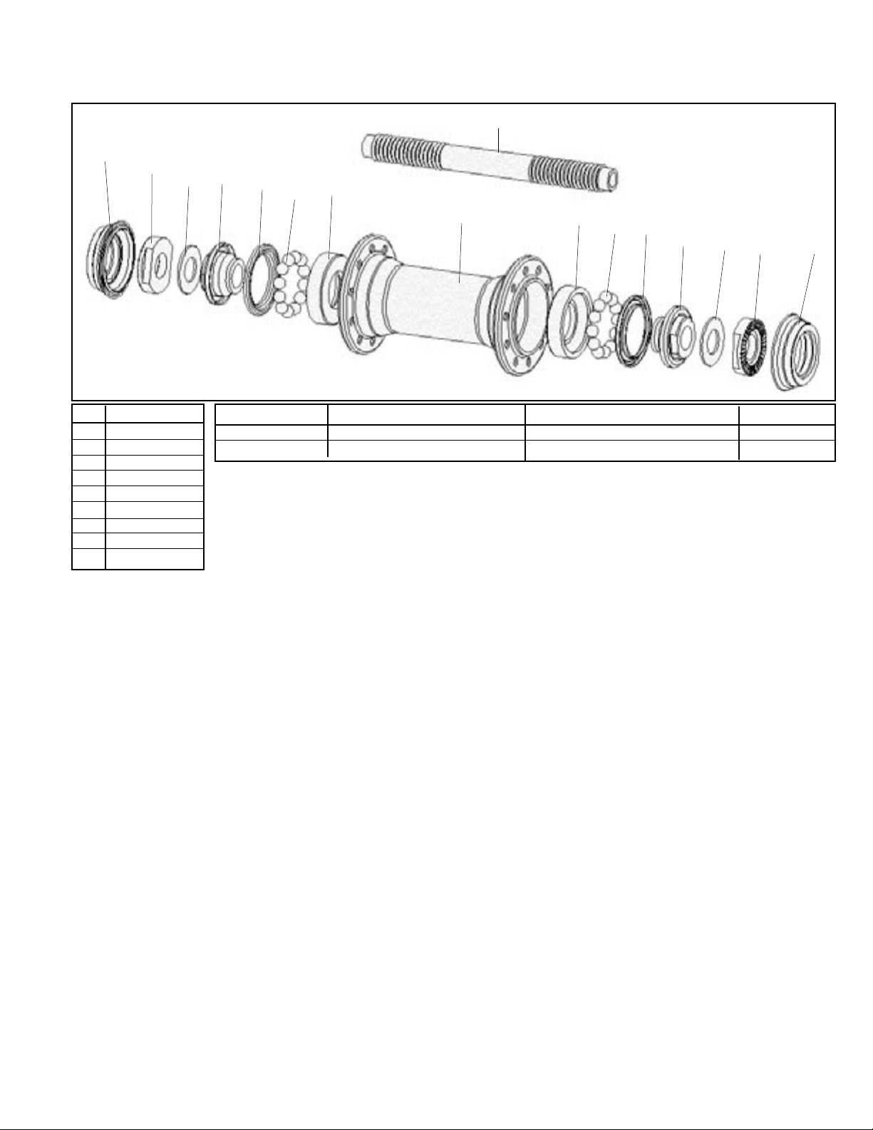
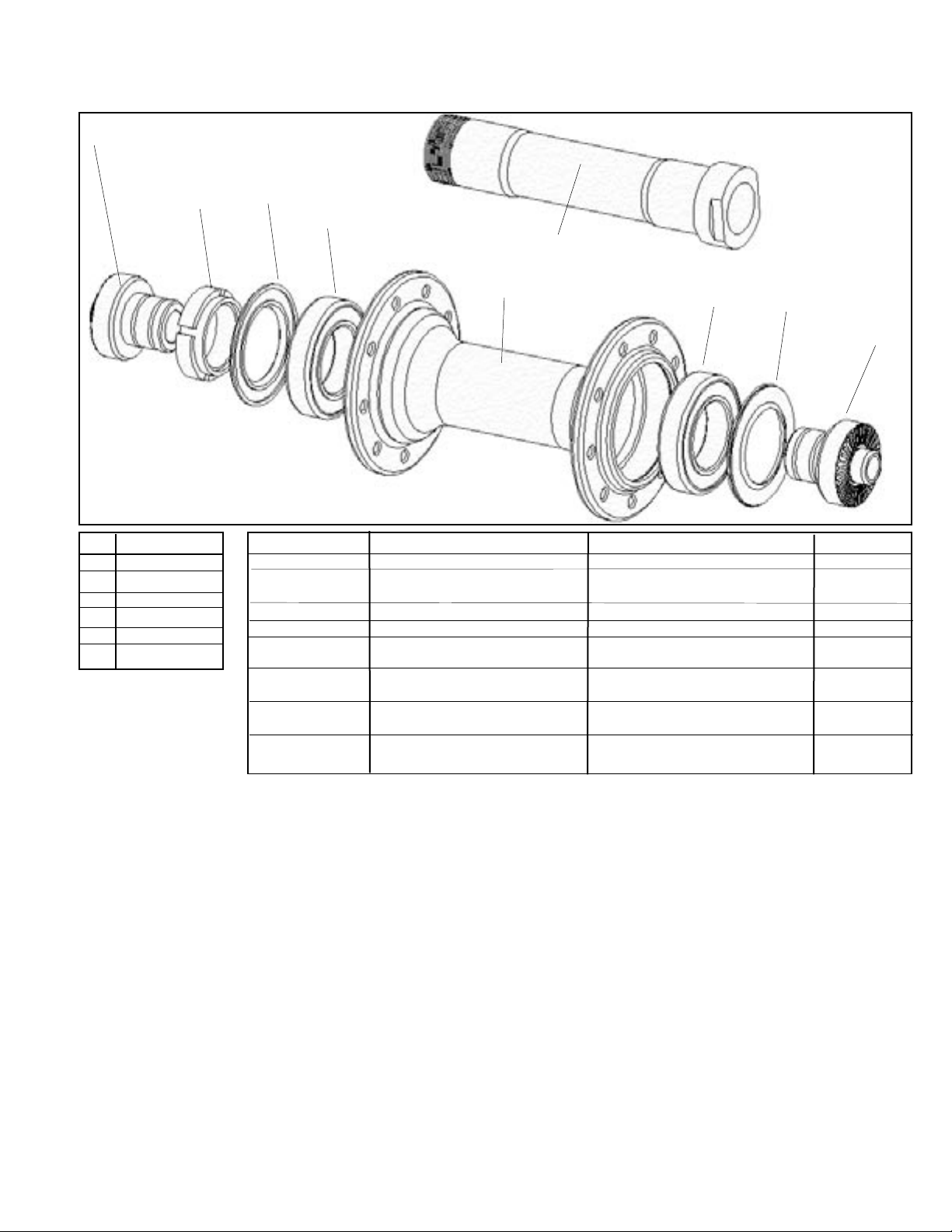
Exploded view and Parts list
9
1
2
4
3
5
7
6
8
7
6
5
4
3
2
1
Pos Description
1 External seal
2 End nut
Description Model year Model for Parts included (qty) TCG Part #
Axle set 99/00/01/02 all 1(2), 4(2), 3(2), 9 68257
Locknut set 99/00/01/02 all 2(2) 68543
3 Washer
4 Ball cone
5 Shell shield
6 Ball bearings
7 Ball cup
8 Hub shell
9 Axle
1999 Bontrager Comp II
O.L.D. . . . . . . . . . . . . . . . . . . . . . . . . . . . . . . . . . . . . . . . . . . . . . . . 100 mm
Spoke hole quantity . . . . . . . . . . . . . . . . . . . . . . . . . . . . . . . . . . . . . . 32°
Spoke hole P.C.D. . . . . . . . . . . . . . . . . . . . . . . . . . . . . . . . . . . . . 38.0 mm
Q.R. rod outer diameter . . . . . . . . . . . . . . . . . . . . . . . . . . . . . . . . . 6 mm
2000/2001/2002/2003 Superstock
O.L.D. . . . . . . . . . . . . . . . . . . . . . . . . . . . . . . . . . . . . . . . . . . . . . . . 100 mm
Spoke hole quantity . . . . . . . . . . . . . . . . . . . . . . . . . . . . . . . . . . . . . . 24°
Spoke hole P.C.D. . . . . . . . . . . . . . . . . . . . . . . . . . . . . . . . . . . . . 38.0 mm
Q.R. rod outer diameter . . . . . . . . . . . . . . . . . . . . . . . . . . . . . . . . . 5 mm
2002/2003 Superstock Disc, Select ATB Disc
O.L.D. . . . . . . . . . . . . . . . . . . . . . . . . . . . . . . . . . . . . . . . . . . . . . . . 100 mm
Spoke hole quantity . . . . . . . . . . . . . . . . . . . . . . . . . . . . . . . . . . . . . . 28°
Spoke hole P.C.D. . . . . . . . . . . . . . . . . . . . . . . . . . . . . . . . . . . . . 58.0 mm
Q.R. rod outer diameter . . . . . . . . . . . . . . . . . . . . . . . . . . . . . . . . . 5 mm
Disc rotor spacing . . . . . . . . . . . . . . . . . . . . . . . . . . . . . . . . . . . . 10.5 mm
Rotor BCD . . . . . . . . . . . . . . . . . . . . . . . . . . . . . . . . . . . . . . . . . . 44.0 mm
2002/2003 Select ATB
O.L.D. . . . . . . . . . . . . . . . . . . . . . . . . . . . . . . . . . . . . . . . . . . . . . . . 100 mm
Spoke hole quantity . . . . . . . . . . . . . . . . . . . . . . . . . . . . . . . . . . . . . . 24°
Spoke hole P.C.D. . . . . . . . . . . . . . . . . . . . . . . . . . . . . . . . . . . . . 38.0 mm
Q.R. rod outer diameter . . . . . . . . . . . . . . . . . . . . . . . . . . . . . . . . . 5 mm
2002/2003 Select Road, Hybrid
O.L.D. . . . . . . . . . . . . . . . . . . . . . . . . . . . . . . . . . . . . . . . . . . . . . . . 100 mm
Spoke hole quantity . . . . . . . . . . . . . . . . . . . . . . . . . . . . . . . . . . . . . . 20°
Spoke hole P.C.D. . . . . . . . . . . . . . . . . . . . . . . . . . . . . . . . . . . . . 38.0 mm
Q.R. rod outer diameter . . . . . . . . . . . . . . . . . . . . . . . . . . . . . . . . . 5 mm
2003 Bontrager Service Manual
3
Front hubs- Loose ball, semi-cartridge; Formula FCM
'99, 2000, 2001 Bontrager Race, Race Disk front wheels
Recommended tools
13mm cone wrench
17mm cone wrench
Adjustable wrench
Hammer (soft faced)
Small slot screwdriver
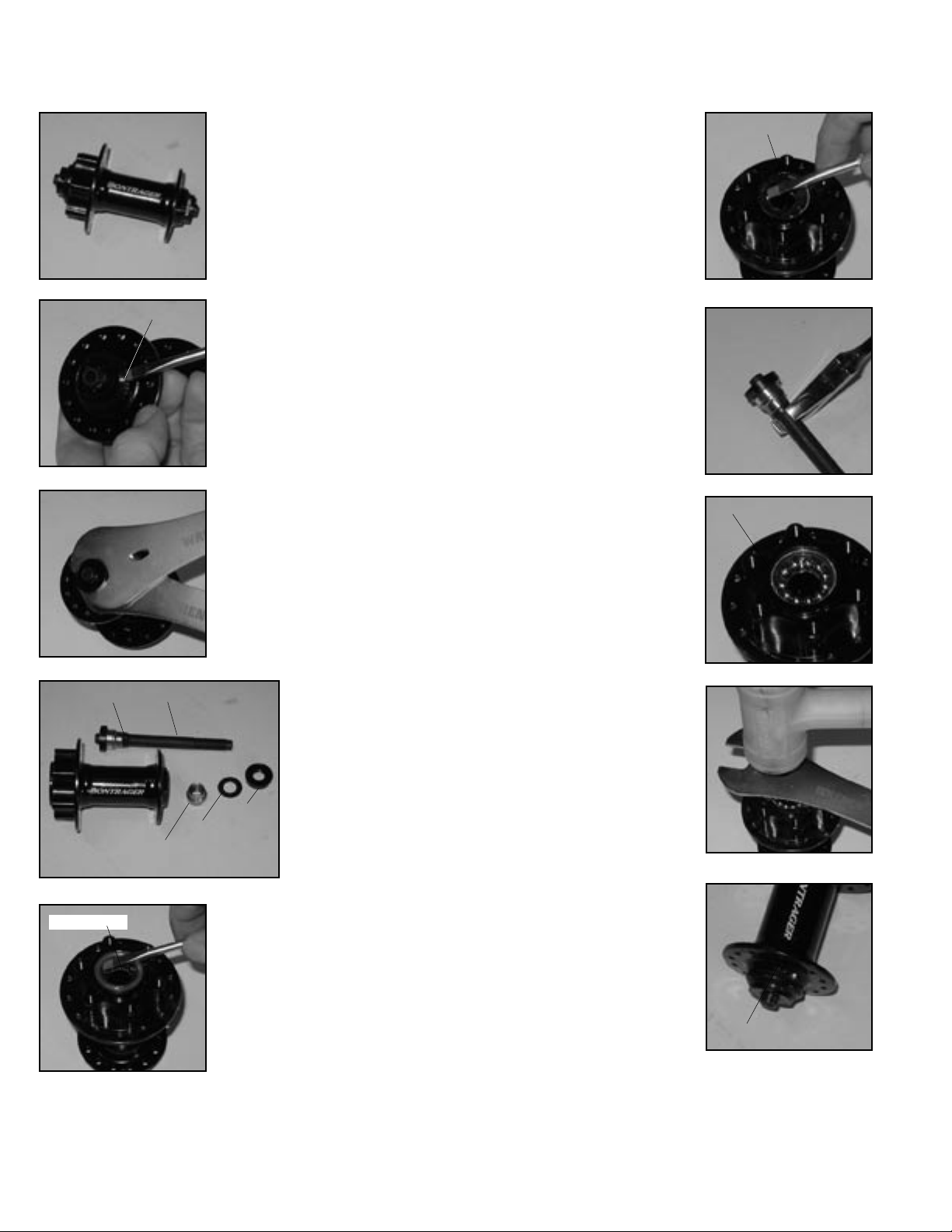
DISASSEMBLY
Hub parts and names are referenced on next page.
Fig. 1B
External seal
Fig. 2B
Fig. 3B
Collar
Fig. 4B
Shell shield
Fig. 5B
Axle
Ball cone
ning surfaces of both the ball cones and the ball cups
(inside the hub). Replace any worn parts.
Note: If the ‘fixed’ ball cone is worn, the axle assembly (axle and ball cone) must be replaced.
Remove the axle
1. Remove external seals
(Fig. 2B) with a screwdriver. Be
careful not to tear or mar the
rubber.
2. On one side of the hub
(usually left), the cone is locked
against a collar on the axle (Fig.
4B). On the other side, place a
13mm cone wrench on the ball
cone. Place a 17mm cone wrench
on the end nut (Fig. 3B). Loosen
the end nut.
3. Remove the end nut, washer, and ball cone from the axle
(Fig. 4B).
4. Slide the axle, with the
other end nut, washer, and ball
cone still attached, out of the hub.
6. Gently insert a thin
screwdriver blade between the
shell shield (Fig. 5B) and bearing seal (Fig. 6B). Pry off the
shell shields from
both sides of the hub.
Do not attempt to pry
off both shield and
seal at the same time
as you may damage
the bearing seal.
End nut
Washer
7. Gently pry off
the bearing seals (Fig.
6B) from both sides of
the hub.
8. If inspection
shows it necessary,
remove the other end nut. Hold
the axle by the wrench flats
(Fig. 7B) while turning the end
nut with a 17mm cone wrench.
Clean and inspect the parts
1. Use solvent to completely
remove all old grease and debris
from the hub, axle, and axle
parts.
2. Inspect the bearing run-
Lubricate bearings and threads
Bearing seal
1. Lubricate the threads on
the axle with Wrench Force™ synthetic grease, or a similar product.
2. Place a bead of grease all
the way around each ball cup,
sufficient to hold the balls.
ASSEMBLY
1. Place eleven 3/16” balls in
the ball cup on one side of the
hub (Fig. 8B).
2. Place the bearing seal,
with the lettered side facing out,
into the ball cup.
3. Place the shell shield, with
its sharp edges facing out, into
the hub. The shell shield is a press
fit, so must be tapped lightly to
fully seat. Lay a cone wrench
over the shell shield and tap the
wrench with a hammer (Fig. 9B)
Bearings in ball cup
to protect the shield and ensure
that it is flush with the shell.
4. Repeat Assembly steps 1-3
for the other side of the hub.
5. Tighten the end nut
against the fixed ball cone
(attached to axle). Hold the axle
with an adjustable wrench on the
axle flats while turning the end
nut with a 17mm cone wrench.
6. Insert the axle through the
hub from either side.
7. Thread the ball cone, washer, and end nut onto the axle in
that order. The serrated surface
of the end nut faces out.
8. Hold the ball cone with a
13mm cone wrench and tighten
the end nut with a 17mm cone
wrench.
9. Check the bearing adjustment by turning the axle with
your fingers. The axle should
spin smoothly without binding or
feeling gritty. There should be no
lateral play of the axle in the hub.
Readjust the hub as necessary,
and re-lock the end nut.
10. Install the external seals.
Make sure the seals properly seal
Seal not seated
against both the end nut and
the hub shell. There should be a
smooth transition from seal to sealing surface. An improperly installed seal (Fig. 10B) will allow rapid contamination of the bearings.
After completing assembly of the hub, check its function by spinning the axle with your fingers. It
should rotate freely without irregular friction. A small amount of lateral play is acceptable if the play is
eliminated when the wheel is installed with the quick release properly closed.
Fig. 6B
Fig. 7B
Fig. 8B
Fig. 9B
Fig. 10B
4
2003 Bontrager Service Manual
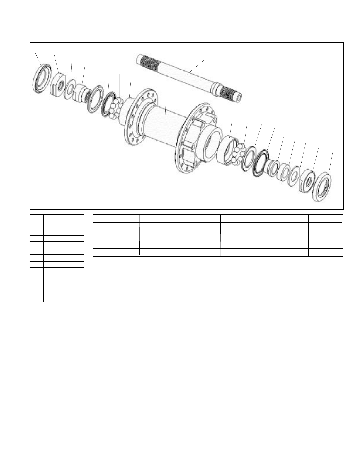
Exploded view and Parts list
1
Note:
Rotor adapter for disc hubs not shown
Rotor spacing varies by model year, see details below.
2
3
4
5
6
10
7
8
9
8
7
6
5
12
11
3
2
1
Pos Description
1 External seal
2 End nut
3 Washer
4 Adjust cone
5 Shell shield
Description Model year Model for Parts included (qty) TCG Part #
Axle set 99/00/01 all 10, 4, 2, 5(2), 11, 6(2), 3(2) 68524
Locknut set 99/00/01 all 2(2) 68527
Rotor adapter 99/00 Hayes, RST Not shown 991083
w/screws
Disc bolt set 99/00 all Not shown 991153
6 Bearing seal
7 Ball bearings
8 Ball cup
9 Hub shell
10 Axle
11 Spacer
12 Ball cone
1999 Race
O.L.D. . . . . . . . . . . . . . . . . . . . . . . . . . . . . . . . . . . . . . . . . . . . . . . . 100 mm
Spoke hole quantity . . . . . . . . . . . . . . . . . . . . . . . . . . . . . . . . . . . . . . 24°
Spoke hole P.C.D. . . . . . . . . . . . . . . . . . . . . . . . . . . . . . . . . . . . . 38.0 mm
Q.R. rod outer diameter . . . . . . . . . . . . . . . . . . . . . . . . . . . . . . . . . 6 mm
1999/2000 Race Disk
O.L.D. . . . . . . . . . . . . . . . . . . . . . . . . . . . . . . . . . . . . . . . . . . . . . . . 100 mm
Spoke hole quantity . . . . . . . . . . . . . . . . . . . . . . . . . . . . . . . . . . . . . . 28°
Spoke hole P.C.D., right . . . . . . . . . . . . . . . . . . . . . . . . . . . . . . 45.0 mm
Spoke hole P.C.D., left . . . . . . . . . . . . . . . . . . . . . . . . . . . . . . . 58.0 mm
Q.R. rod outer diameter . . . . . . . . . . . . . . . . . . . . . . . . . . . . . . . . . 6 mm
Disc rotor spacing . . . . . . . . . . . . . . . . . . . . . . . . . . . . . . . . . . . . 16.0 mm
Rotor BCD . . . . . . . . . . . . . . . . . . . . . . . . . . . . . . . . . . . . . . . . . . 44.0 mm
2001 Race Disk
O.L.D. . . . . . . . . . . . . . . . . . . . . . . . . . . . . . . . . . . . . . . . . . . . . . . . 100 mm
Spoke hole quantity . . . . . . . . . . . . . . . . . . . . . . . . . . . . . . . . . . . . . . 28°
Spoke hole P.C.D., right . . . . . . . . . . . . . . . . . . . . . . . . . . . . . . 45.0 mm
Spoke hole P.C.D., left . . . . . . . . . . . . . . . . . . . . . . . . . . . . . . . 58.0 mm
Q.R. rod outer diameter . . . . . . . . . . . . . . . . . . . . . . . . . . . . . . . . . 6 mm
Disc rotor spacing . . . . . . . . . . . . . . . . . . . . . . . . . . . . . . . . . . . . 10.5 mm
Rotor BCD . . . . . . . . . . . . . . . . . . . . . . . . . . . . . . . . . . . . . . . . . . 44.0 mm
2000/2001 Race
O.L.D. . . . . . . . . . . . . . . . . . . . . . . . . . . . . . . . . . . . . . . . . . . . . . . . 100 mm
Spoke hole quantity . . . . . . . . . . . . . . . . . . . . . . . . . . . . . . . . . . . . . . 24°
Spoke hole P.C.D. . . . . . . . . . . . . . . . . . . . . . . . . . . . . . . . . . . . . 38.0 mm
Q.R. rod outer diameter . . . . . . . . . . . . . . . . . . . . . . . . . . . . . . . . . 5 mm
2003 Bontrager Service Manual
5
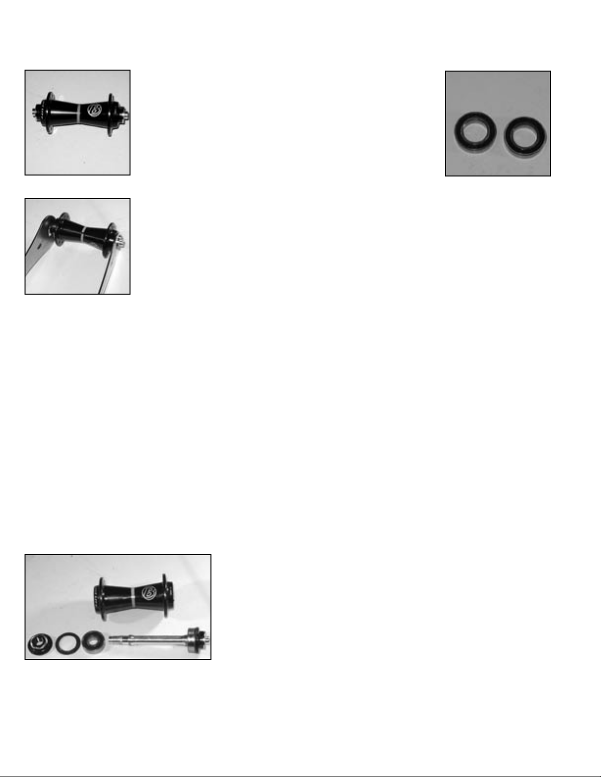
Front hubs- Cartridge bearing, alloy axle
2002/2003 Bontrager Race, Race Disc front wheels
Fig. 1C
Fig. 2C
Fig. 3C
Fig. 4C
End caps
Axle nut
Recommended tools
17mm cone wrench
Special hook spanner
Hammer and broad punch
Bearing removal tool
Bearing press
DISASSEMBLY
Hub parts and names are referenced on next page.
Remove the axle
1. Remove axle end caps
(Fig. 2C) by sliding them out of
the axle with your fingers.
2. Hold the axle with a
17mm cone wrench (Fig. 3C)
while loosening the axle nut
with the special hook spanner
(Fig. 4C).
3. Partially unthread the
axle nut (Fig. 5C) until it
slightly protrudes past the end
of the axle.
4. Tap the axle nut with a
soft-faced hammer until the axle
slides through the opposite bearing. Once loose, the axle should
come out with your fingers.
5. Remove the axle nut, and
extract the axle (Fig. 6C).
6. Gently insert a thin screwdriver blade between the bearing
seal (Fig. 7C) and bearing. Pry
off the bearing seals from both
sides of the hub.
7. Insert a bearing removal
tool into the bearing. Place a
blunt punch through the hub
and against the bearing removal
tool. Tap the punch with the
hammer to drive the bearing out
of the hub (Fig. 8C). Repeat for
the other bearing.
ASSEMBLY
1. Press a bearing into the
hub with a bearing press.
Note: the black seal faces out (Fig. 9C).
2. Press the second bearing
with the bearing press.
3. Place the bearing seals
into the hub with the lettered
surface facing out.
6. Insert the axle through the
hub from either side.
7. Thread the axle nut onto
the axle.
8. Hold the axle with a 17mm
cone wrench and tighten the axle
nut with the special hook spanner until finger tight.
Do not over-tighten the axle nut. The axle should turn freely
with no lateral play in the hub shell.
9. Press the axle end caps
into both ends of the axle.
After completing assembly of the hub, check its function by
spinning the axle with your fingers. It should rotate freely
without irregular friction. A small amount of lateral play
is acceptable if the play is eliminated when the wheel is
installed with the quick release properly closed.
Axle
Axle nut
Fig. 5C
Fig. 6C
Fig. 7C
Bearing
seat
Fig. 8C
Clean and inspect the parts
1. Wipe old grease or debris from the hub bearing
seats.
2. Normally, bearings are not re-used. If you are reinstalling an old bearing, wipe off any grease or debris
from both the inner and outer surfaces.
Do not use solvent on the bearing, as the solvent will
contaminate the grease. This may cause bearing failure.
Lubricate bearings and threads
1. Lubricate the threads on the axle with Wrench
Force™ synthetic grease, or a similar product.
2. Lightly grease the inner and outer surfaces of
each bearing.
6
2003 Bontrager Service Manual
Fig. 9C
Exploded view and Parts list
1
2
Note:
Rotor adapter for disc hubs not shown
Rotor spacing varies by model year, see details below.
Pos Description
1 End cap
2 Adjustable nut
3 Seal
4 Bearing
5 Hub shell
6 Axle
3
Description Model year Model for Parts included (qty) TCG Part #
Seal 99/00/01 all 3(2) 68261
Bearing 99/00/01 all 4(2) 68262
#6903
Axle set 99/00/01 all 6, 4(2) 68263
Adjustable nut 99/00/01 all 2 68264
End cap, 99/00/01/02 all 1(2) 211645
20.5mm O..D.
Rotor adapter 99/00 Hayes, RST Not shown 991083
w/screws
Disc bolt set 99/00 all Not shown 991153
4
6
5
4
3
1
Special 99/00/01/02 all Not shown, see Fig. 4C 68259
hook spanner
2002 Race
O.L.D. . . . . . . . . . . . . . . . . . . . . . . . . . . . . . . . . . . . . . . . . . . . . . . . 100 mm
Spoke hole quantity . . . . . . . . . . . . . . . . . . . . . . . . . . . . . . . . . . . . . . 24°
Spoke hole P.C.D. . . . . . . . . . . . . . . . . . . . . . . . . . . . . . . . . . . . . 42.0 mm
Q.R. rod outer diameter . . . . . . . . . . . . . . . . . . . . . . . . . . . . . . . . . 5 mm
2002 Race Disk
O.L.D. . . . . . . . . . . . . . . . . . . . . . . . . . . . . . . . . . . . . . . . . . . . . . . . 100 mm
Spoke hole quantity . . . . . . . . . . . . . . . . . . . . . . . . . . . . . . . . . . . . . . 28°
Spoke hole P.C.D., right . . . . . . . . . . . . . . . . . . . . . . . . . . . . . . 45.0 mm
Spoke hole P.C.D., left . . . . . . . . . . . . . . . . . . . . . . . . . . . . . . . 58.0 mm
Q.R. rod outer diameter . . . . . . . . . . . . . . . . . . . . . . . . . . . . . . . . . 5 mm
Disc rotor spacing . . . . . . . . . . . . . . . . . . . . . . . . . . . . . . . . . . . . 10.5 mm
Rotor BCD . . . . . . . . . . . . . . . . . . . . . . . . . . . . . . . . . . . . . . . . . . 44.0 mm
2003 Bontrager Service Manual
7
2003 Bontrager Service Manual
Needs photos and text
Front hubs- Cartridge bearing, threaded alloy axle
2002/2003 Bontrager Race Lite Road front wheels
Recommended tools
17mm cone wrench (2)
Hammer and broad punch
Bearing press
DISASSEMBLY
Hub parts and names are referenced on next page.
Remove the axle
1. Remove one of the thread-
Fig. 1H
Fig. 2H
second bearing from the axle. To do this, clamp the
middle of the axle, loosen the end cap, and remove it.
Support the bearing and tap the axle out with a softfaced hammer.
ed axle end caps (Fig. 2H) by
loosening with the pair of 17mm
cone wrenches.
2. With one end cap
removed, drive the axle from
the hub shell with a soft-faced
hammer.
3. Place a broad punch
through the hub, and tap the
punch with a hammer to drive
the second bearing (Fig. 3H),
with its seal, from the hub.
4. If needed, remove the
ASSEMBLY
1. Press a new bearing onto
the axle with a bearing press.
Note: the black seal faces out (Fig. 4H).
2. Place the hub seal onto the
axle, and thread on the axle end
cap. Clamp the middle of the axle
and tighten the axle end cap with
the 17mm cone wrench.
3. Press the bearing, with the
axle attached, into the hub.
4. Press the second bearing into the hub.
Note: the black seal faces out (Fig. 4H).
5. Place the hub seal over the bearing, and press into
the hub shell.
6. Thread on the second axle end cap, and tighten with
the 17mm cone wrench.
Do not over-tighten the axle nut. The axle should turn freely with no lateral play in the hub shell.
Fig. 4H
Clean and inspect the parts
1. Wipe old grease or debris from the hub bearing
seats.
2. Normally, bearings are not re-used. If you are reinstalling an old bearing, wipe off any grease or debris
from both the inner and outer surfaces.
Do not use solvent on the bearing, as the solvent will
contaminate the grease. This may cause bearing failure.
Lubricate bearings and threads
1. Lubricate the threads on the axle with Wrench
Force™ synthetic grease, or a similar product.
2. Lightly grease the inner and outer surfaces of
each bearing.
8
Fig. 3H
2003 Bontrager Service Manual
 Loading...