

Page 1
Owner’s Manual
Using the
Ducted Gas Central Heating
Dual Cycle Refrigerated Air Conditioning
Ducted Evaporative Air Conditioning
with your
multi-appliance
Navigator Control
Radio Frequency & Low Voltage
Please keep this important manual in a safe place. It is the owner’s responsibility to ensure that
regular maintenance is carried out on units. Failure to do so will void all guarantees beyond
statutory and legal requirements.
Navigator Control 5442280A
www.climatetechnologies.com.au
Page 2

Multi-Appliance Navigator Control
Contents
INTRODUCTION.............................................................................................................................. 4
1. YOUR MULTI-APPLIANCES ......................................................................................................................................... 4
2. GENERAL INFORMATION............................................................................................................................................5
IMPORTANT INSTALLATION NOTICE...................................................................................................5
MODEL & SERIAL NUMBER................................................................................................................... 5
LIMITATIONS........................................................................................................................................... 5
WARRANTY............................................................................................................................................. 5
SAFETY
NAVIGATING THE CONTROLS ..................................................................................................... 5
3. TYPES OF NAVIGATOR CONTROLLER MODEL........................................................................................................6
4. FEATURES OF NAVIGATOR CONTROLLER.............................................................................................................. 7
5. USING THE 8 BUTTONS ..............................................................................................................................................8
6. THE LCD DISPLAY ....................................................................................................................................................... 9
7. BACKLIGHT...................................................................................................................................................................9
8. QUICK START...............................................................................................................................................................9
9. SETTING DAY AND TIME...........................................................................................................................................10
10. SIMPLE MANUAL OPERATION................................................................................................................................11
11. APPLIANCE TYPE SELECTION ...............................................................................................................................11
12. CHILD LOCK ............................................................................................................................................................. 12
………………………………………………………………………………………………….5
13. PARING NAVIGATOR CONTROLLER (RF Only).....................................................................................................12
14. RESET THE NAVIGATOR CONTROLLER............................................................................................................... 13
DUCTED GAS CENTRAL HEATING............................................................................................ 14
14. GENERAL INFORMATION........................................................................................................................................15
IMPORTANT NOTICE ...........................................................................................................................15
ASSEMBLY............................................................................................................................................15
15. SAFETY ..................................................................................................................................................................... 16
SAFETY & OWNER RESPONSIBILITY.................................................................................................16
PRECAUTIONS ..................................................................................................................................... 16
FEATURES............................................................................................................................................16
POWER OR GAS INTERRUPTION....................................................................................................... 16
16. USING YOUR NAVIGATOR CONTROL ................................................................................................................... 17
MANUAL CONTROL.............................................................................................................................. 17
ECONOMY MODE.................................................................................................................................18
FAN MODE ............................................................................................................................................ 19
ZONING................................................................................................................................................. 19
PROGRAMMING YOUR NAVIGATOR CONTROLLER........................................................................20
17. HEATER MAINTENANCE .........................................................................................................................................22
18. SCHEDULED MAINTENANCE..................................................................................................................................22
19. PROBLEM SOLVING ................................................................................................................................................ 23
DUAL CYCLE REFRIGERATED AIR CONDITIONING ............................................................... 24
20. GENERAL INFORMATION........................................................................................................................................25
IMPORTANT NOTICE ...........................................................................................................................25
MODEL & SERIAL NUMBER................................................................................................................. 25
ASSEMBLY............................................................................................................................................25
21. SAFETY ..................................................................................................................................................................... 25
Navigator Control Page 2
Page 3

Multi-Appliance Navigator Control
Contents
SAFETY & OWNER RESPONSIBILITY.................................................................................................25
PRECAUTIONS ..................................................................................................................................... 25
FEATURES............................................................................................................................................25
POWER INTERRUPTION...................................................................................................................... 25
22. USING YOUR NAVIGATOR CONTROLLER ............................................................................................................26
COOL STATE ........................................................................................................................................26
HEAT STATE.........................................................................................................................................26
HEAT & COOL STATE ..........................................................................................................................26
ZONING................................................................................................................................................. 27
23. PROGRAMMING YOUR NAVIGATOR CONTROL...................................................................................................27
USING THE PROGRAMMING SEQUENCE..........................................................................................27
DUCTED EVAPORATIVE AIR CONDITIONING.......................................................................... 28
24. INTRODUCTION ....................................................................................................................................................... 29
GENERAL INFORMATION
25. UNIT OPERATION .................................................................................................................................................... 29
EXHAUST .............................................................................................................................................. 29
WATER MANAGEMENT .......................................................................................................................30
26. USING YOUR NAVIGATOR CONTROLLER ............................................................................................................31
MANUAL MODE ....................................................................................................................................31
THERMO MODE....................................................................................................................................31
BOOST MODE.......................................................................................................................................32
FAN MODE ............................................................................................................................................ 32
27. PROGRAMMED OPERATION ..................................................................................................................................32
…………………………………………………………………………….29
28. DUCTED EVAPORATIVE AIR CONDITIONER MAINTENANCE .............................................................................33
FILTER PADS........................................................................................................................................33
WATER TANK........................................................................................................................................ 33
MOTOR AND FAN.................................................................................................................................34
ELECTRICAL.........................................................................................................................................34
BLEED OFF ........................................................................................................................................... 34
PUMP.....................................................................................................................................................34
WATER DISTRIBUSTION .....................................................................................................................34
NO SEASONAL MAINTENANCE .......................................................................................................... 34
29. PROBLEM SOLVING ................................................................................................................................................ 35
CONTROL SETUP ........................................................................................................................ 36
30. SETTING UP THE NAVIGATOR CONTROLLER - GENERAL................................................................................. 36
INSTALLATION...................................................................................................................................... 36
31. COMMISSIONING CHECK LIST ...............................................................................................................................37
WARRANTY .................................................................................................................................. 39
SERVICE........................................................................................................................................ 43
Navigator Control Page 3
Page 4
Multi-Appliance Navigator Control
Navigating the Controls
INTRODUCTION
1. YOUR MULTI-APPLIANCES
You have chosen one of the world's most advanced Navigator Control systems. The Navigator Controller is
intended for use in controlling BONAIRE Gas Heaters, Evaporative Coolers or Dual Cycle Refrigerated
Coolers. At any one time, the Navigator Controller can control multiple units. The Navigator Controller also
allows simultaneous control of a combined Gas Heater / Refrigerative Cooler units (Dual Cycle).
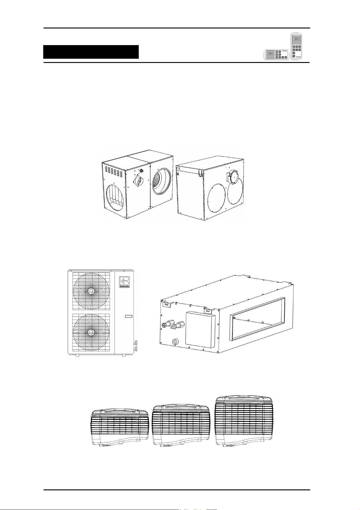
Your Navigator Controller has been designed to operate various BONAIRE products:
HEATING – MB-3, 4, 5 Star BONAIRE Ducted Gas Central Heaters.
DUAL CYCLE COOLING – BONAIRE Gas Central Heater with a matched BONAIRE Dual Cycle
Refrigerative Cooling System attached.
FRESH AIR CONDITIONERS – BONAIRE Ducted Evaporative Air Conditioners.
Navigator Control Page 4
Page 5
Multi-Appliance Navigator Control
Navigating the Controls
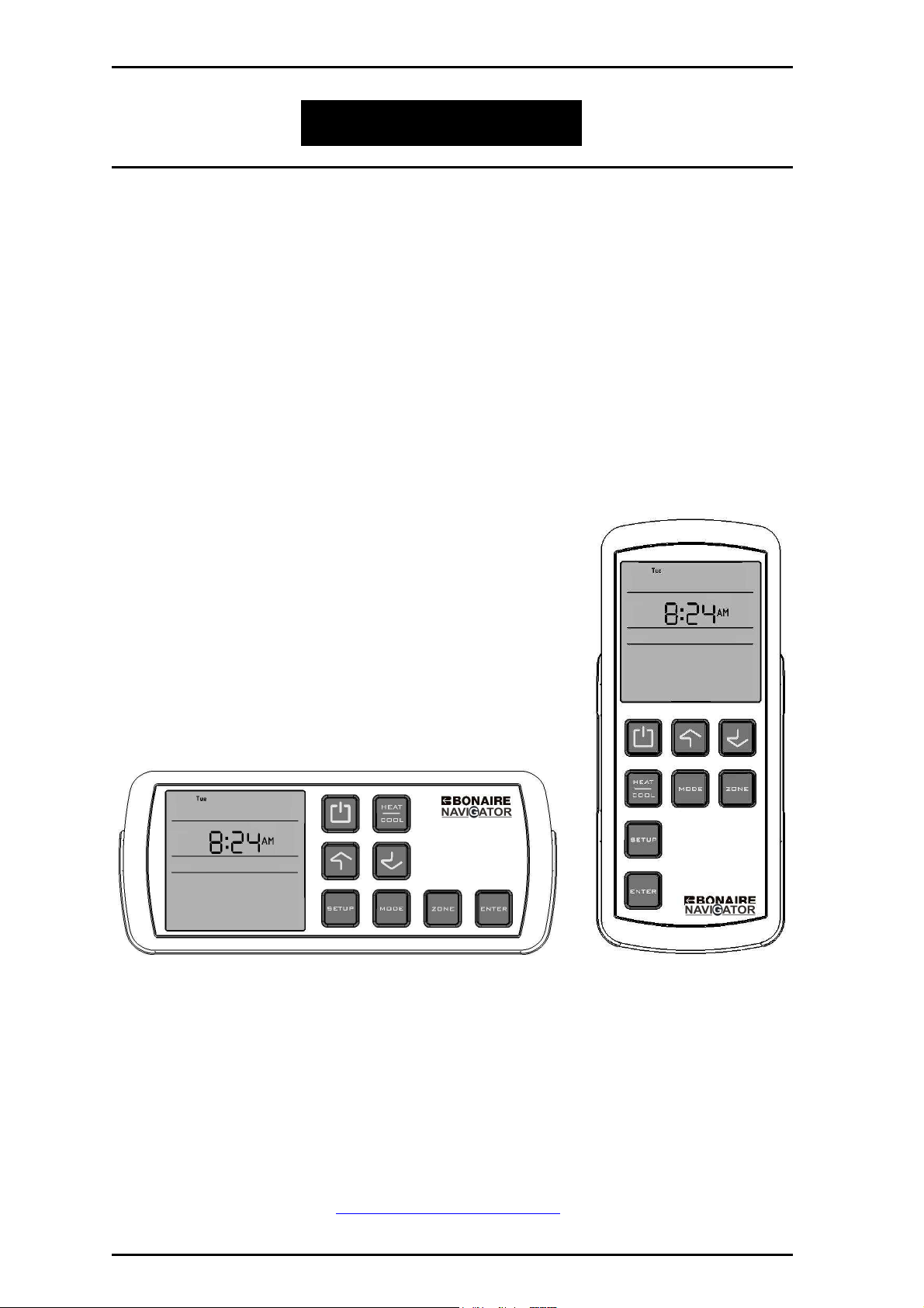
Your Navigator Controller is available in two versions
1. Wall Mounted Control (Wired)
2. Remote Control (Wireless)
These operating notes cover both versions. Whether hand held or wall mounted take advantage of the
versatility your Navigator Controller offers.
Use your Navigator Controller to reduce your energy bills by selectively conditioning part of or your entire
home at an economical reduced rate or by setting programs to suit your needs (Not available on Evaporative
Air Conditioning).
Your Navigator Controller is designed in Australia to suit Australian conditions and will ensure that your
home is comfortable all year round.
2. GENERAL INFORMATION.
IMPORTANT INSTALLATION NOTICE
A licensed person is required to install BONAIRE equipment. If the equipment is not installed in accordance
with the installation instructions and the governing body regulations, Climate Technologies reserves the right
to refuse service on non compliant installations.
Subject to state regulations and by laws, a certificate of compliance must be issued for the electrical and
plumbing works certifying that the work complies with all the relevant standards.
NOTE: Only a registered person will have insurance protecting their workmanship.
MODEL & SERIAL NUMBER
Your appliance model number, serial number and model description are located on the appliance data plate
on the end of the heater, inside the Evaporative cooler in the vicinity of the electronic controls or on the Dual
Cycle outdoor end panel and Refrigerated indoor end panel. These details should also be in the warranty
section of this booklet.
You will need this information, should your appliance require servicing, spare parts or just if you require
additional information about this product.
LIMITATIONS
The Navigator Controller does not support systems that have both evaporative Cooler and Dual cycle
Refrigerated Cooler units together.
WARRANTY
Warranty service work must only be carried out by Climate Technologies service division or its authorised
service providers. Please refer to the warranty section.
S
AFETY
These appliances are not intended for use by persons (including children) with reduced physical, sensory or
mental capacities, or lack of experience and knowledge, unless they have been given supervision or
instruction concerning use of the appliance by a person responsible for their safety.
Children should be supervised to ensure that they do not play with these appliances.
Navigator Control Page 5
NAVIGATING THE CONTROLS
Page 6
Multi-Appliance Navigator Control
Navigating the Controls
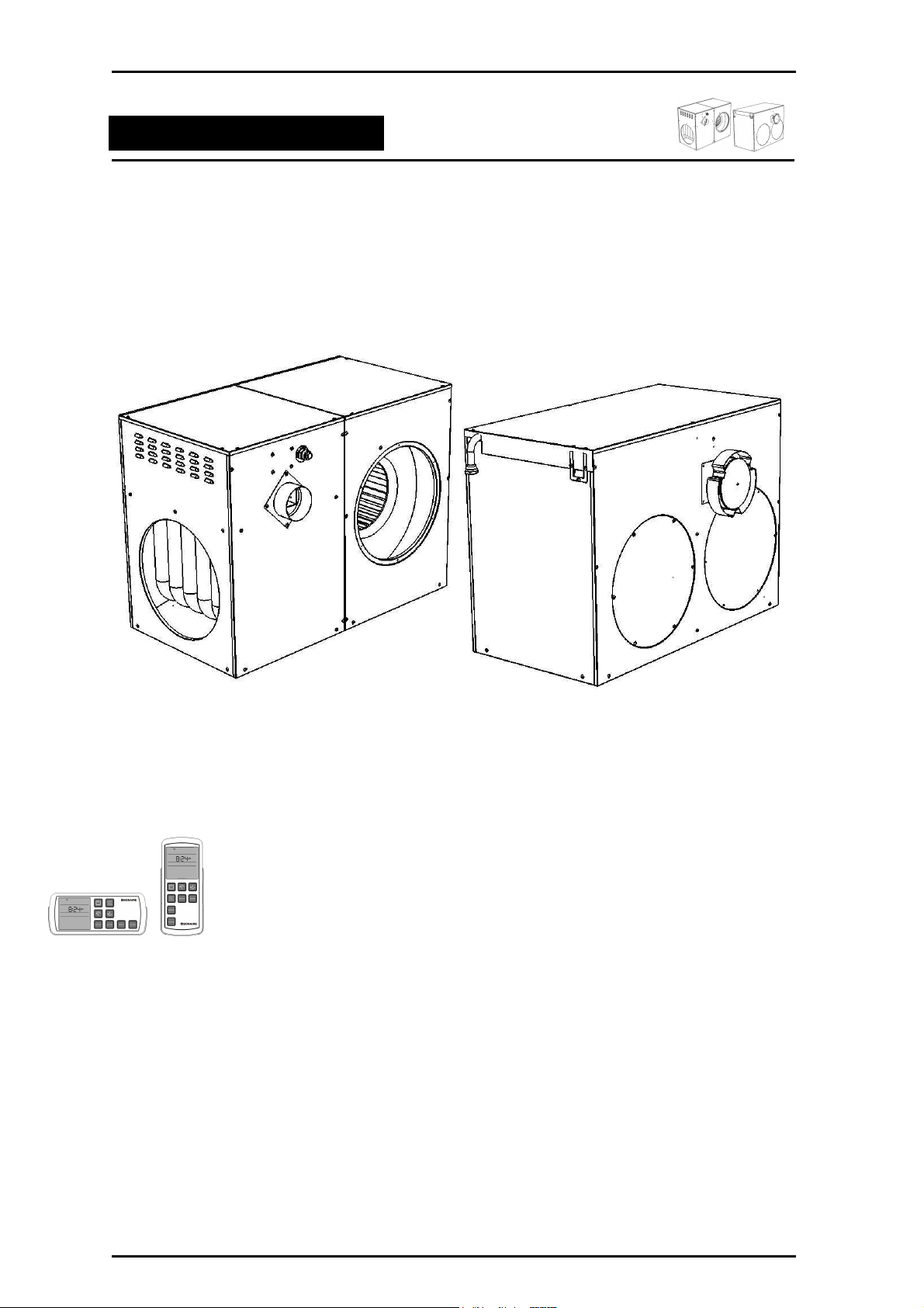
3. TYPES OF NAVIGATOR CONTROLLER MODEL
Use these pictures to identify which model you have.
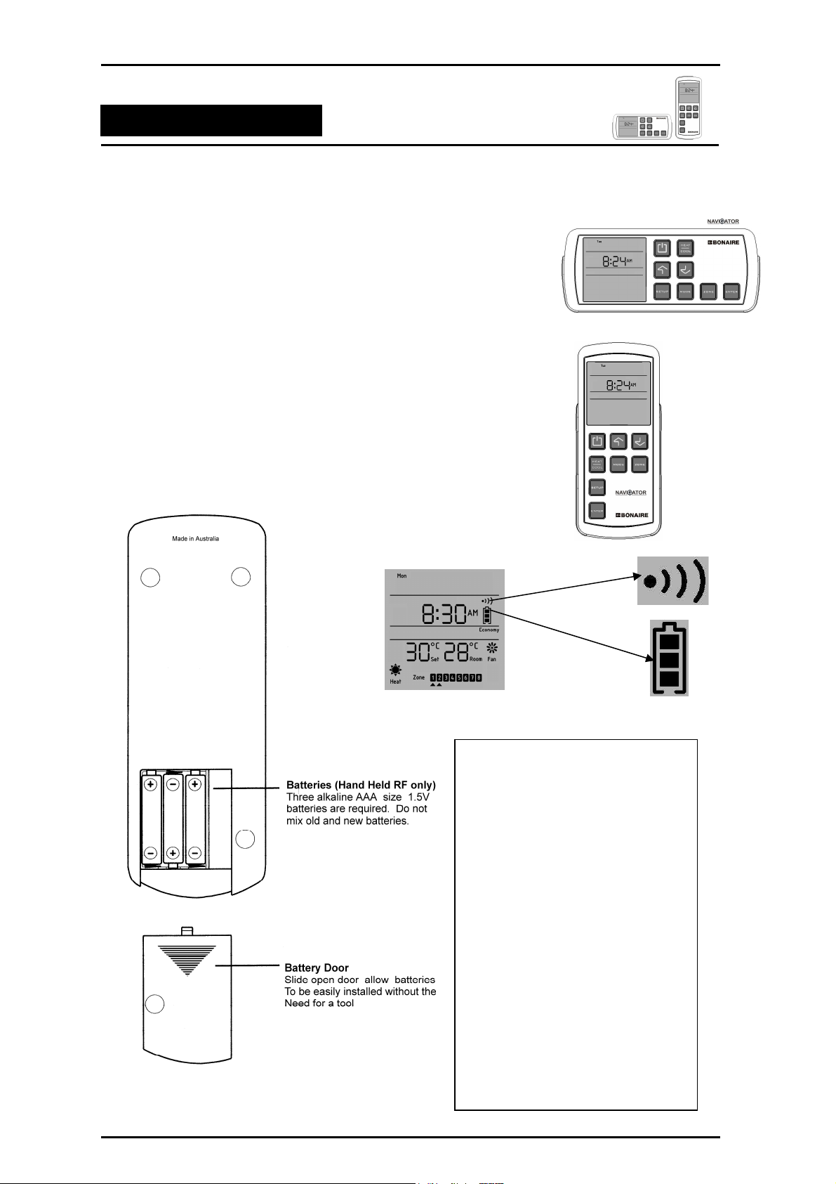
WALL MOUNTED CONTROL
This model is mounted permanently in the cradle on your wall. No
batteries are required. Power is supplied via the same cable that takes the
controller's signals to your heating and / or cooling appliances.
REMOTE CONTROL
This model is hand held and will operate your appliances from most areas
of your home – See IMPORTANT NOTE for exceptions.
The remote Navigator Controller (RF) is powered by 3 AAA batteries and
the battery icons are always indicating the battery strength. The wave icon
indicates transmission of a communication to your appliance.
To reduce the risk of possible RF
interference, do not locate your RF
control near any electrical
equipment e.g. TV’s, computers,
fridges, telecommunications and HI
FI equipment or close to metal
objects or window frames.
IMPORTANT NOTE
Other wireless devices around your
home can also cause interference
such as wireless door bells, gates
door openers, or baby monitors &
intercoms. Such interference can
impede the operation of your
appliance.
Navigator Control Page 6
Ensure the RF control unit is not
exposed to excessive heat,
humidity, moisture or dampness.
Page 7
Multi-Appliance Navigator Control
Navigating the Controls
4. FEATURES OF THE NAVIGATOR CONTROLLER
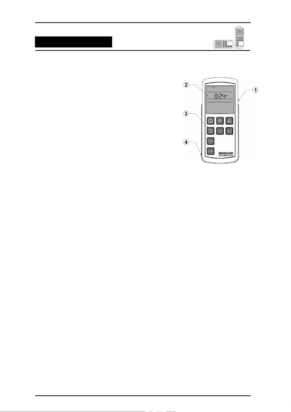
1. TEMPERATURE SENSOR
It Measures the room temperature for thermostatic operation
(REMOTE SHOWN).
2. LCD DISPLAY
Displays operational status of mode, time, day, room temperature,
set temperature, temporary temperature, fan speed, batteries and
programming.
3. SOFT TOUCH BUTTONS
8 button layout
4. NAVIGATOR CONTROL CRADLE
••••
Fixed to the wall to permanently mount the LV wall control.
••••
Fixed to the wall for easy access to the portable RF control.
OTHER FEATURES
• Time of day: The user can set the Time Format, Hours, Minutes and Day.
• Zone control: The Navigator Controller allows you to select the area or section of your house for
heating and cooling. * If installed by installer, zone motors not supplied.
• Child Lock: The user can protect the Navigator Control program.
• Programmed operation: The Navigator Controller can program the appliances by day or week.
• Home automation compatibility
• Control of multiple appliances: Your Navigator Controller is designed to operate multiple
appliances.
• Error reporting: Your Navigator Controller will report any errors or faults.
• Installer system setup procedure
• Service, diagnostic and error log modes
Navigator Control Page 7
Page 8
Multi-Appliance Navigator Control
Navigating the Controls
5. USING THE 8 BUTTONS
The following explains the function of each of the button:
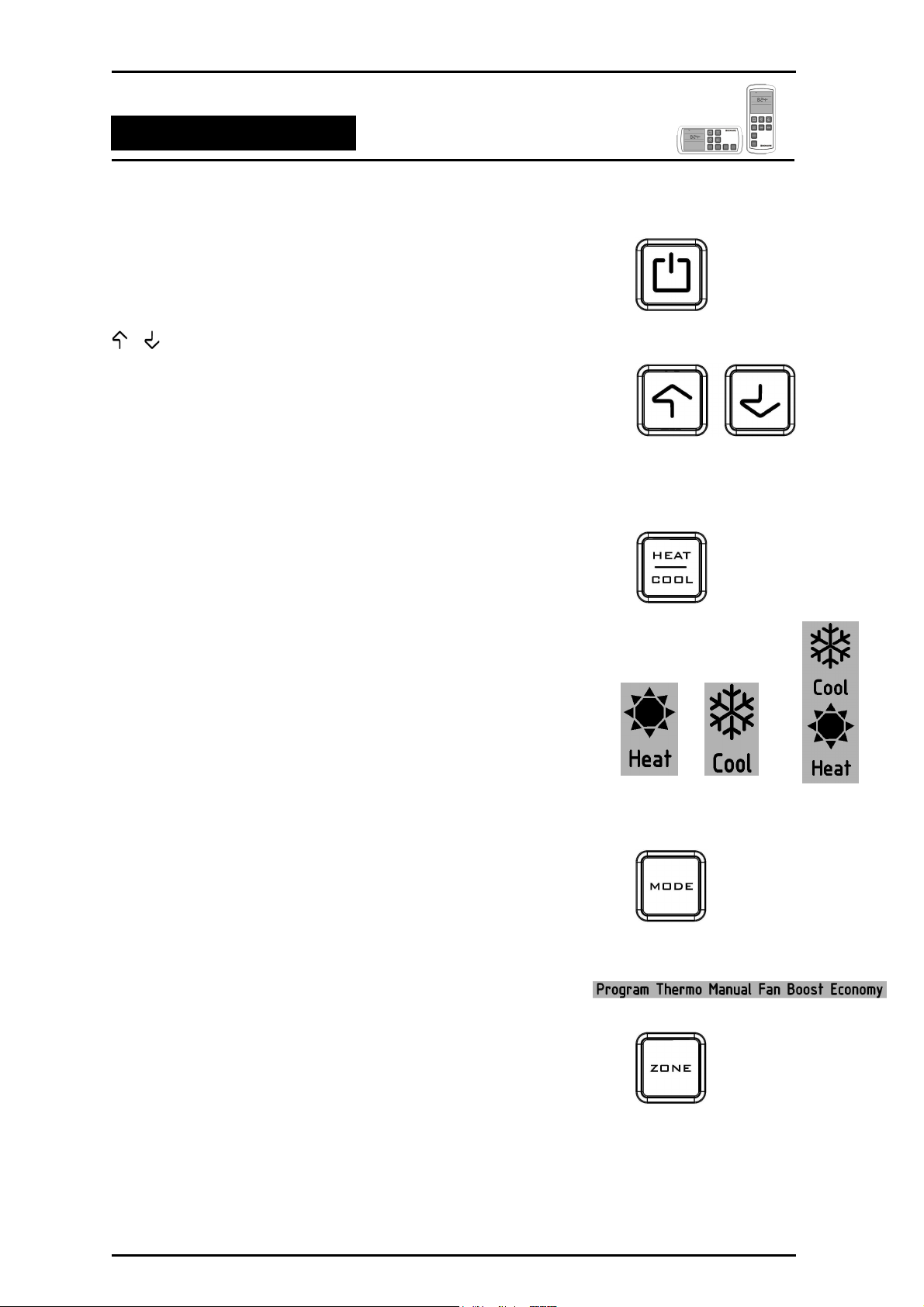
ON/OFF
• Turns your heating and / or cooling appliances ON and OFF.
BUTTONS
• Press & hold UP/DOWN button to increase or decrease settings.
• Or press & release UP/DOWN buttons to increase or decrease one
point at a time. Settings include day, time, temperature, fan speed.
The UP/DOWN buttons are also used to select the different zones
•
or programs available.
HEAT/COOL
• Press to select from the heating and or cooling choices (In most
cases you will only be able to see the titles for the appliances that
you have installed. If there is only one appliance installed, pressing
the heat/cool button will result in “Error” being displayed).
• Heat: Ducted Gas Central Heaters
• Cool: Evaporative or Dual Cycle Refrigerative Air Conditioning
• Heal/Cool: Ducted Gas Central Heater and Dual cycle
Refrigerated Air Conditioning
MODE
• The MODE button allows the user to select the operating mode for
the currently selected appliance type.
• There are six modes of operation defined. Thermo and Fan are
common to all appliances. Program, Manual, Boost and Economy
are only available on certain appliance types.
ZONE
The ZONE button allows the user to select the area or section
of your house for heating and cooling control (If zones are
available).
Navigator Control Page 8
Page 9
Multi-Appliance Navigator Control
Navigating the Controls
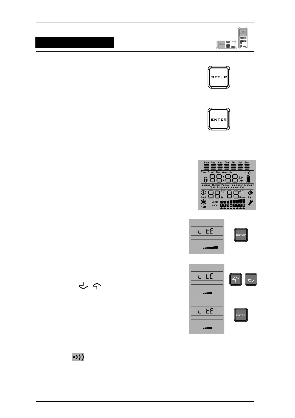
SETUP
• The SETUP button is used to configure the Navigator Controller in
either the ON or OFF condition. It allows time setting, program and
advanced setup. The advanced setup will only be allowed if the
Navigator Controller is in the OFF condition.
ENTER
• Press and release the ENTER button to save settings when in SET
TIME, PROGRAM mode and ZONE setting.
• Press and release the ENTER button to immediately send
instructions.
6. THE LCD DISPLAY
The Navigator Controller display shows different information depending on
the functions in use. The Navigator Controller usually shows only those
items relevant to the appliances you have installed.
7. BACKLIGHT
The Navigator Controller provides a BLUE and ORANGE backlight. The
blue backlight is illuminated for cooling appliances and the orange
backlight is illuminated for heating appliances. To adjust the backlight
level,
1. Press and hold the SETUP button until the “LitE” appears on
the display.
2. Press the or button to decrease or increase the
backlight level.
3. Press the ENTER button to select the backlight level adjustment.
8. QUICK START
To give you time to choose your settings the Navigator Controller pauses
15 seconds and then sends its signal to your Heater/Cooler. Watch for the
transmit symbol on the screen. This means that the signal has
been sent. (RF only)
Your Navigator Controller is designed to automatically detect the
appliances connected. Controller options not required for your connected
Navigator Control Page 9
Page 10
Multi-Appliance Navigator Control
Navigating the Controls
appliances will be hidden and not displayed on your Navigator Controller,
therefore some menu items shown in this instruction may not appear.
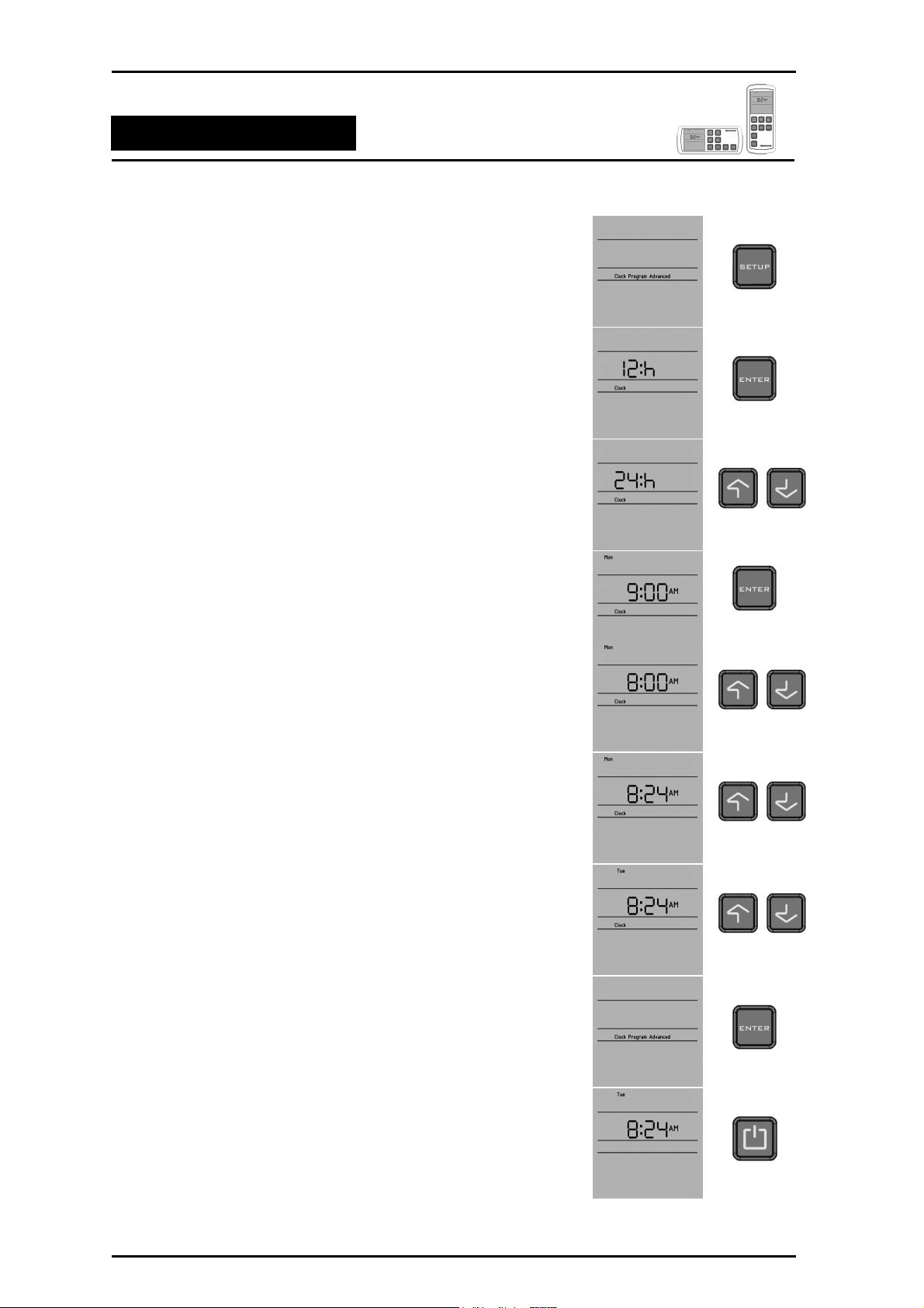
9. SETTING DAY AND TIME
On first power up or reset, the time display will flash 12:00 am and shall
remain so until the user sets the time or it receives a set time command
from another device. The user can set the time with the controller in an
ON or OFF state.
To set the time,
1. Press the SETUP button and it will display the Clock, Program and
Advanced (OFF state only) icons on the display. The Clock icon will
be flashing.
2. Press the ENTER button to select the clock and it will display the
time format 12: h or 24: h. To select the time format, press the
UP/DOWN button and then press the ENTER button as required.
3. The display will then flash the HOURS. Press the UP/DOWN
button to increase or decrease the hours. Press the ENTER button
to set hours.
4. The display will flash the MINUTES. Press the UP/DOWN button to
increase or decrease the minutes. Press the ENTER button to set
minutes.
5. The display will flash the DAY on the top row of the display. Press
the UP/DOWN button to change the day. Press the ENTER button
to select the day.
6. The Navigator Controller will display Clock, Program and Advanced
icons. Press the ON/OFF button (OFF state) or the SETUP (ON
state) button to go to the main display.
Navigator Control Page 10
Page 11
Multi-Appliance Navigator Control
Navigating the Controls
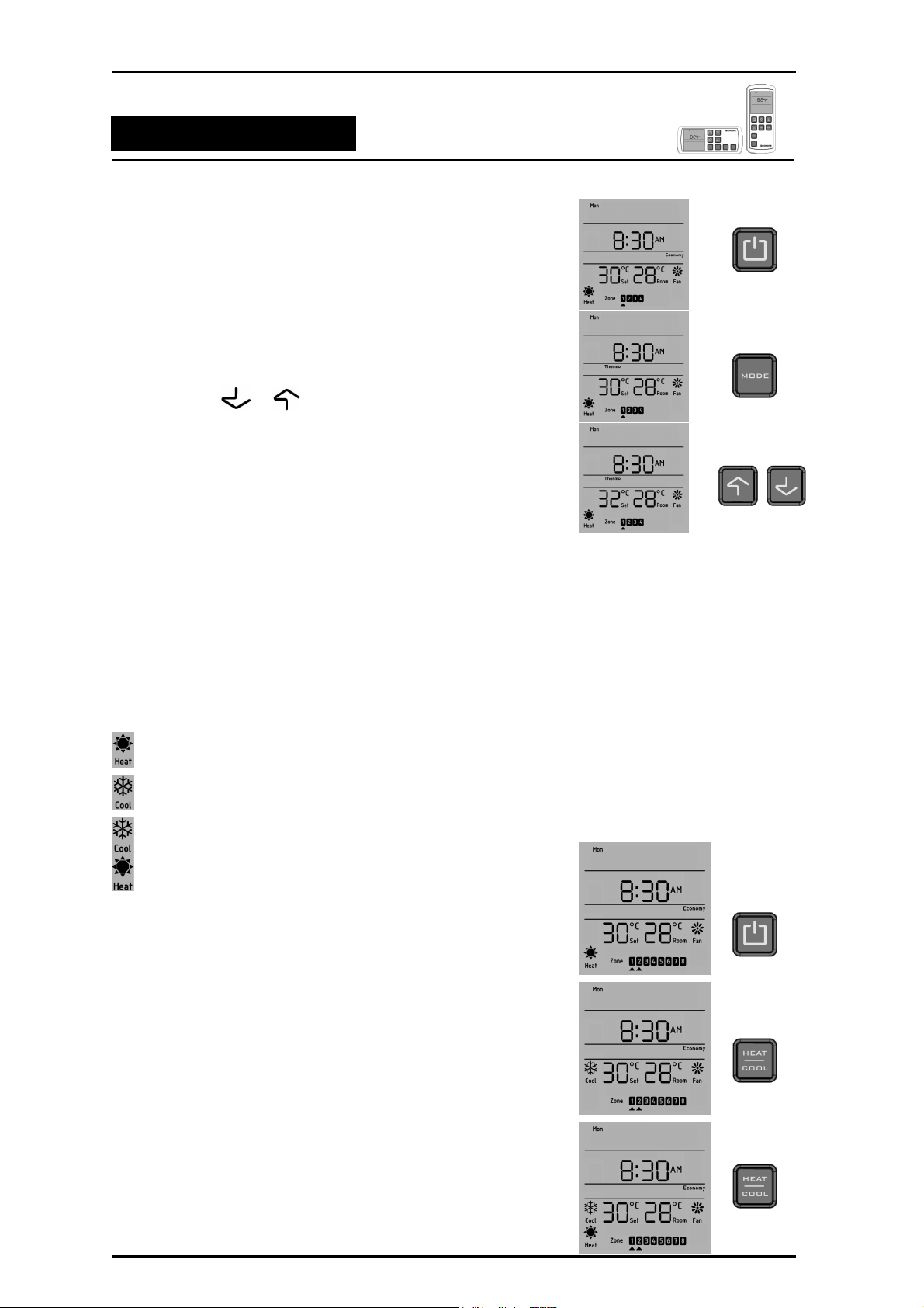
10. SIMPLE MANUAL OPERATION
Here's all you have to do to get the system going (If the installer hasn't
already done it for you). To operate the Navigator Controller,
1. Turn the Navigator Controller ON by pressing the ON/OFF button.
2. Press the MODE button to select different modes of operation.
3. Press the or buttons to set the temperature.
Your unit will now operate in manual mode.
NOTE: When the back light is blue, it is in cooling mode.
When the back light is orange, it is in heating mode.
11. APPLIANCE TYPE SELECTION
Your Navigator Controller can operate multiple appliances (where more
than one type of appliance has been connected). You can select your
appliance type by pressing HEAT/COOL button. You will see the Heat,
Cool or Heat/Cool icons on the display of the Navigator Controller.
NOTE: Heat/Cool is only allowed on installations with a heater and
Dual Cycle Refrigerative cooling.
Icon indicates that, your appliance is in heating state.
Icon indicates that, your appliance is in cooling state.
Icon indicates that, your appliance is in heating and cooling state.
To select different appliances,
1. Turn the Navigator Controller ON by pressing the ON/OFF
button.
2. Press the HEAT/COOL button to scroll through the different
appliances if more appliance than one appliance is connected.
3. Press the ENTER button to select your desired appliance type.
Navigator Control Page 11
Page 12
Multi-Appliance Navigator Control
Navigating the Controls
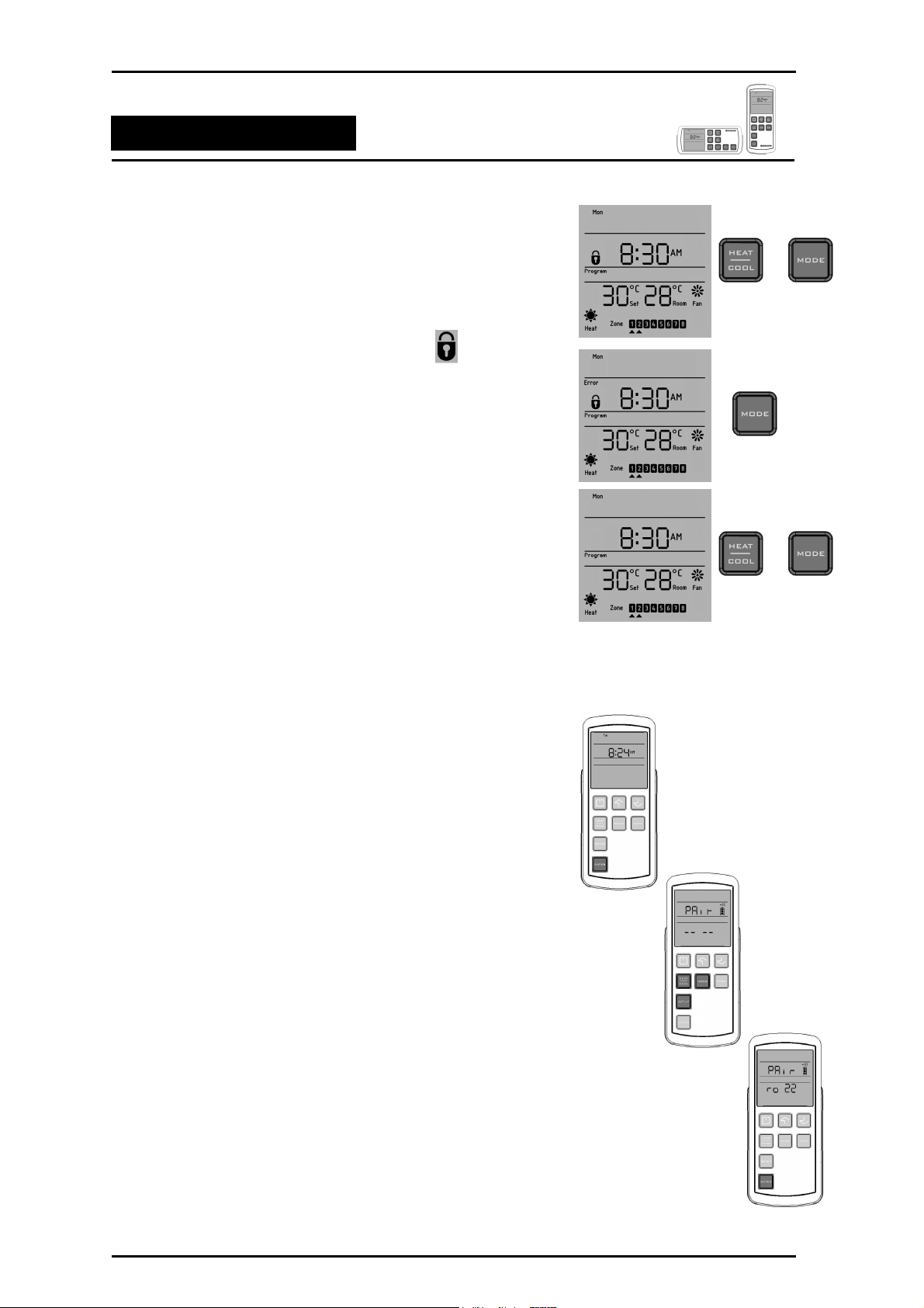
12. CHILD LOCK
Your Navigator Controller provides a special child lock function to protect
the current operation or program. To activate CHILD LOCK function at
any time,
1. Press and hold the HEAT/COOL and MODE buttons.
2. The child lock is enabled and the lock icon will appear on the
display. Any key press will be ignored and the error icon will
flash.
3. Press and hold the HEAT/COOL and MODE buttons again to
disable the child lock.
13. PAIRING YOUR NAVIGATOR CONTROLLER (RF Only)
Note that this is normally undertaken by the installer.
The BONAIRE Navigator Controller and transceiver does not
have any pairing information when they are delivered from the
factory.
The RF handset must be “paired” to it’s transceiver (antenna). On
the first power up, the transceiver will request to join with
Navigator Controller for period of a 30 min window and it will flash
a green light. If it does not join within that time, it will join the next
time the unit is powered up.
To put the Navigator Control into pairing mode -
1. Press & hold the ENTER button for 3 seconds.
2. Press the Heat/Cool, Mode & Setup buttons in sequence.
The display will flash the “PAir”.
3. After few seconds the display will show the controller number.
For example “ro 22”. Press the ENTER button to pair with
transceiver.
NOTE: Bars on the display will indicate signal strength.
4. Press the ON/OFF button to go back to the main display.
The RF handset and the transceiver are now paired together ready
for use.
Navigator Control Page 12
Page 13
Multi-Appliance Navigator Control
Navigating the Controls
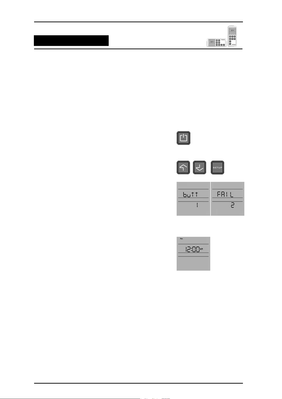
14. RESETTING THE NAVIGATOR CONTROLLER
CAUTION! This will reset the controller to it’s factory default settings
and so after a reset, the control may need to be set up again to suit
your installation requirements (depending on how your system was
first set up).
To reset the Navigator Controller to the default setting,
1. Press & hold the ON/OFF button for 3 seconds.
2.
Then press the UP, DOWN and SETUP buttons in sequence.
3.
After few seconds, the display will flash “butt” followed by
“FAIL”.
4.
When the Navigator Controller has finished resetting, the display
will flash default settings as shown.
Navigator Control Page 13
Page 14
Multi-Appliance Navigator Control
Ducted Gas Central Heating
DUCTED GAS CENTRAL HEATING
Owner’s Operation and Maintenance Instructions
Please keep this important manual in a safe place. It is the owner’s responsibility to ensure that
regular maintenance is carried out on the Ducted Gas Central Heater. Failure to do so will void all
guarantees beyond statutory and legal requirements.
Navigator Control Page 14
Page 15

Multi-Appliance Navigator Control
Ducted Gas Central Heating
Congratulations on purchasing a BONAIRE Ducted Gas Central Heating system, an exciting new product
manufactured by Climate Technologies.
Wholly designed and manufactured in Australia, BONAIRE Ducted Gas Central Heaters represent an
exciting new development in warm air furnace design. It embodies the latest advances in gas heating
technology.
Your heater is supported by Climate Technologies, Australia’s most advanced manufacturer of a complete
range of climate control products.
To ensure you fully enjoy the benefits of your BONAIRE Ducted Gas Central Heater, please read these
instructions carefully and keep them handy for future reference.
If operated and maintained in accordance with this manual, your BONAIRE unit will provide you with years of
warm and environmentally friendly operation. Please take the time to read this manual.
14. GENERAL INFORMATION
IMPORTANT NOTICE
A licensed person is required to install any Heating/Cooling equipment. If the equipment is not installed
in accordance with the installation instructions and the governing body regulations, Climate Technologies
reserves the right to refuse service on non compliant installations.
Subject to state regulations and by laws, a certificate of compliance must be issued for the electrical and
plumbing work certifying that the work complies with all the relevant standards.
Note: Only a registered person will have insurance protecting their workmanship.
MODEL & SERIAL NUMBER
Your appliance model number, serial number and model description are located on the appliance data plate
on the end of the heater or under the lid in the vicinity of the electronic controls. These details should also be
in the warranty section of this booklet.
You will need the model & serial number, should your appliance require servicing, spare parts or just
if you require additional information about this product.
ASSEMBLY
There is no assembly required of this Ducted Gas Central Heater. Your Dealer or installer will carry out all
assembly and commissioning upon installation.
Navigator Control Page 15
Page 16

Multi-Appliance Navigator Control
Ducted Gas Central Heating
15. SAFETY
SAFETY & OWNER RESPONSIBILITY
The manufacturer and its service providers reserve the right to refuse service unless safety and accessibility
to the unit can be guaranteed in accordance with the installation instructions and Australian Standards. The
cost of any extra equipment required to provide access to the unit for servicing is the responsibility of the
owner.
This appliance is not intended for use by young children or infirm persons unless they have been adequately
supervised by a responsible person to ensure that they can use the appliance safely.
Young children should be supervised to ensure that they do not play with the appliance.
PRECAUTIONS
DO NOT PLACE ARTICLES ON OR AGAINST THIS APPLIANCE.
DO NOT USE OR STORE FLAMMABLE MATERIALS NEAR THIS APPLIANCE.
DO NOT SPRAY AEROSOLS IN THE VICINITY OF THIS APPLIANCE WHILE IT IS IN OPERATION.
DO NOT PLACE ARTICLES IN FRONT OF OR OVER THE RETURN AIR GRILLE.
FEATURES
Your BONAIRE Ducted Gas Central Heater has all the safety devices to ensure safe operation. These
devices conform to the standards set out by Standards Australia.
POWER OR GAS INTERRUPTION
Should there be an interruption to the power supply during the heating operation the controls will
automatically turn off the gas.
NOTE: If there is an interruption to the power supply, the Navigator Controller will remember all
settings and programs for 30 minutes. After 30 minutes without power the Navigator
Controller will revert to the default settings.
Depending on the unit installed, the product may not restart when power is resumed. In these cases it will be
necessary to manually reset the controller.
Should there be an interruption to the gas supply, the heater will endeavor to re-light and if unsuccessful it
will lock out. (This is part of the safety features). Should this occur the heater will need to be reset.
Please refer to your problem-solving chart to assist resolving other problems.
Navigator Control Page 16
Page 17

Multi-Appliance Navigator Control
Ducted Gas Central Heating
16. USING YOUR NAVIGATOR CONTROL
There are 2 ways to operate your Navigator Controller. You can use MANUAL CONTROL and select the
your mode of operation or you can set a PROGRAM for automatic operation.
NOTE: If there is only a central heater fitted in the house, the Navigator Controller will default to
Heat. Your Navigator Controller is programmed to automatically detect the appliances connected.
Controller options not required for your connected appliances will be hidden and not displayed on
your Navigator Controller, therefore some menu items shown in this instruction may not appear.
MANUAL CONTROL
In manual control you can operate in thermo, economy, boost or fan mode and operate zones.
THERMO MODE
In THERMO mode, the Heater will run at an output power level as
required to achieve the requested comfort level. To use the THERMO
mode,
1. Turn the Navigator Controller ON by pressing the ON/OFF button.
2. Press the MODE button until the Thermo icon appears on the
display and press the ENTER button to select.
3. Press the or buttons to decrease or increase the set
temperature. You can set the temperature from 10°C to 32°C.
4. The Navigator Controller measures the room temperature using a
thermostat inside its case. When the room temperature is colder
than the SET TEMP the Heater will come on after a 30 second
ignition process.
NOTE: Do not leave the Remote Navigator controller where
air from a heater outlet or other heat & cold sources impact
on it as it may affect the thermostat operation.
5. The Navigator Controller will run both the modulating (4 star, 5
star) and non modulating (3 star) heaters until it measures the
room temperature as equal to your SET TEMP. The thermostat
will then turn off the heater until the temperature falls 0.5°C below
the set temperature before restarting.
6. For 4 and 5 star heaters, the operation of the heater is as follows:
• If at start up, the room temperature is more than 2.0° below
the set temperature, the central heater will start up at high
fan speed and high gas rate quickly bringing your house up
to temperature.
• As the room temperature gets closer to the set temperature
the central heater will reduce the room air fan and the gas
rate to the burner.
Navigator Control Page 17
Page 18

Multi-Appliance Navigator Control
Ducted Gas Central Heating
• When the room temperature reaches the set temperature the
central heater will shut down.
• When the room temperature has dropped approximately 0.5º
below the set temperature the unit will restart.
• As your activities vary, you may find you need different
temperature settings, e.g. a temperature comfortable for
sitting is usually too warm compared to when you’re moving
about.
• For economical operation, set a low SET TEMP during the
day when you are active, or use the ECONOMY mode.
Switch the Navigator Controller OFF when asleep and ON
again when awake. These cost saving functions can be
programmed to operate automatically (see Programmed
Control).
7. Press the ON/OFF button to switch the heater OFF.
8. The Navigator Controller remembers your SET TEMP setting and
uses it the next time you turn it ON.
ECONOMY MODE
The ECONOMY mode operates the heater at the lowest power level if the
room temperature is below the set temperature. The Navigator Controller
turns off the unit when the set temperature is reached and then back on
when the room temperature drops again. To operate the ECONOMY
mode,
1. Turn the Navigator Controller ON by pressing the ON/OFF
button.
2. Press the MODE button until the Economy icon appears on the
display and press the ENTER button to select.
3. Press the or buttons to decrease or increase the set
temperature. You can set the temperature from 10°C to 32°C.
Navigator Control Page 18
Page 19

Multi-Appliance Navigator Control
Ducted Gas Central Heating
BOOST MODE
The BOOST mode operates the heater at maximum power level if the
room temperature is below the set temperature. The Navigator Controller
turns off the unit when the set temperature is reached. The Navigator
Controller turns the unit back on when room temperature drops again. To
operate BOOST mode,
1. Turn the Navigator Controller ON by pressing the ON/OFF button.
2. Press the MODE button until the Boost icon appears on the display
and press the ENTER button to select the Boost mode.
3. Press the UP/DOWN button to decrease or increase the set
temperature. You can set the temperature from 10°C to 32°C.
FAN MODE
In FAN mode the heater operates the fan only to circulate air. In this
mode, the fan speed can be adjusted to the desired level. To operate the
FAN mode,
1. Turn the Navigator Controller ON by pressing the ON/OFF button.
2. Press the MODE button until the FAN icon appears on the display
and press the ENTER button to select.
3. Press the UP/DOWN button to decrease or increase the fan speed.
You can set the fan speed up to 8 levels.
ZONING
The Navigator Controller is capable of controlling up to 8 switched zones
and one unswitched zone. If more zone control is required than the
standard 4 zones which is supplied with a 4 or 5 star heater, then a zone
extension kit is available. This will increase zone control from 4 to 8 with
one unswitched zone. Selecting ZONE only applies if your home is fitted
with optional motorised ductwork dampers (please consult your installer)
that allow opening or closing of each section of ducting.* Not available on
3 star units.
The Navigator Controller will show only installed zones. If no dampers are
fitted and the installer correctly configures the heater, no zones will be
shown and zone setup cannot be selected.
In homes with more than one zone, at least one zone must be open at all
times. The default zone is 1 if no other is selected.
To set the open or closed status of a ZONE:
1. Press and release the ZONE button. ZONE 1 (or the current open
zone) will flash.
2. Press the
Navigator Control Page 19
or button to select the zone you wish to control.
Page 20

Multi-Appliance Navigator Control
Ducted Gas Central Heating
3. Press the ZONE button to toggle a zone open or closed. Repeat to
open or close more zones. The arrow will display under the
selected zone on the LCD screen that are set to open / on.
4. Press the ENTER button to exit the Zone setup.
Now the Heater operates only in your selected zones.
PROGRAM MODE
To operate the PROGRAM mode,
1. Turn the Navigator Controller ON by pressing the ON/OFF
button.
2. Press the MODE button until the Program icon appears on the
display & press the ENTER button to select.
PROGRAMMING YOUR NAVIGATOR CONTROLLER
Programming your Navigator Controller will save time and energy. Your
heating and or cooling system will only operate when you need it and at
your chosen comfort levels. Determine your most comfortable settings,
program them and let your Navigator Controller do the rest automatically.
PROGRAMMING SEQUENCE
Heater / Dual Cycle Refrigerated Air Conditioning
If you've never programmed your Navigator Controller before (or it’s been
a while) remember it's easiest to program the whole week to the same
settings (by selecting the whole week MON TUE WED THU FRI SAT SUN
day choice) and then program variations for particular days or the
weekend as you become more familiar with programming.
If the Controller exits program mode it may be because you've paused
longer than about 1 minute to make your next choice. All the settings
you've made up to then will be saved. Just switch back to program mode,
scroll through your settings using the ENTER button and carry on from
where you left off. The following is the programming sequence for the
Navigator Controller-
1. Press the SETUP button and it will display Clock, Program and
Advanced (OFF state only) icons on the screen. Currently Clock is
flashing.
2. Press the
3. Press the
modified (Single Day, Week Days, Weekend or Whole Week).
Press the ENTER button to complete the selection.
Navigator Control Page 20
or button to select Program and press ENTER.
or button to change the day or day group to be
Page 21

Multi-Appliance Navigator Control
Ducted Gas Central Heating
4. You can set 4 program periods in one single day or day group. To
select the program periods press the or
the ENTER button. (NOTE: Set these program periods
according to the time)
5. The HOURS icon will now be flashing. To set the desired hour
press the
proceed. The MINUTES icon will now flash. Using the
button set the minutes. Press the ENTER button to proceed.
NOTE: If you want to disable a period, set time to “--:--“.
6. The temperature will now be flashing. To set desired temperature
press the
You can set the temperature from 10°C to 32°C.
NOTE: If you want set an off period, set temperature to “--”.
7. ZONE will flash at bottom of the display (If switched zones are
installed). ZONE 1 or the current zone will flash.
or button and press the ENTER button to
or button and then press the ENTER button.
button and press
or
8. Press the
the ZONE button to open/close the selected ZONE and arrow will
appear under the selected zone.
9. Press the ENTER button to finish. The Navigator Controller will
display and perform a “Sort” function. After the sorting function the
Navigator Controller will display the next period.
10. Press the SETUP button to go to the main screen.
If you want to make corrections to what you've entered, press the SETUP
button and select program by pressing the or button. Now press
the ENTER button and you'll start the programming sequence again.
Scroll through the program selections by pressing the ENTER button and
change any items as you come to them.
If the unit is running under the Program mode, the user may temporarily
override the programmed settings by setting the temperature and the
zone. The “Override” will flash on the display when you change the
temperature or zone in program mode and this will revert back to standard
programming.
or button to select the different zones. Press
Navigator Control Page 21
Page 22

Multi-Appliance Navigator Control
Ducted Gas Central Heating
17. HEATER MAINTENANCE
WARNING: Before commencing any maintenance work on your unit, isolate the power at the
supply (Switch Board).
NOTE: It is essential that your central heater be maintained in accordance with this manual. Failure
to do so will affect the life of the product and reduce the level of efficiency.
ELECTRICAL
No general maintenance is required to the electrical system.
A Qualified Electrician should only carry out electrical connections and maintenance.
RETURN AIR GRILLE FILTER
If your heating system has a filter in the return air grille, it is extremely important it is cleaned every 3 – 4
weeks during the operating period to ensure correct operation of the heating unit. Failure to do so may
cause your heater to stop because of over temperature and cause an unnecessary service call not covered
by warranty.
FLUE
The flue and cowl assembly should be clean and free of obstructions.
18. SCHEDULED MAINTENANCE
Your BONAIRE Ducted Gas Central Heater should be serviced annually to ensure trouble free operation.
1. To ensure that your heater continues to operate at peak efficiency it is recommended that it be
periodically serviced by a qualified service technician
2. Fan blades, motors, ignition systems and burners should be checked every year. The heater cabinet
and immediate surroundings should be kept clean.
3. Replace the batteries in the Radio Frequency Navigator Controller (where fitted) at the start of each
heating season with new AAA alkaline batteries.
OTHER ITEMS
There are other items your Climate Technologies service technician will attend to for scheduled
maintenance.
Service Call: Service contact details are located on page 43 of this manual.
Navigator Control Page 22
Page 23

Multi-Appliance Navigator Control
Ducted Gas Central Heating
19. PROBLEM SOLVING
WHAT IF CENTRAL HEATER WILL NOT OPERATE!
Question Y/N Solution
Has the unit been run
1.
since installation?
Yes Refer to question 4
No Check the unit is turned on at the power point and the gas shut off valve
is turned on. If not call the installer to commission the unit.
Is the unit installed in a
2.
new home?
Has the installer run the
3.
unit?
Is the set temperature
4.
greater that the room
temperature?
Is the thermostat in
5.
program mode?
Has there been a known
6.
power surge?
Yes Refer to question 3
No Refer to question 4
Yes Refer to question 4
No Check the unit is turned on at the power point and the gas shut off valve
is turned on. If not call the installer to commission the unit.
Yes Turn the unit off (for more than 2 secs) and then on to reset unit. If the
unit still does not start call for service. (refer to solution 6 for reset
instructions)
No Increase the set temperature so the thermostat calls for heat.
Yes The heater may be programmed to be OFF. To operate the heater
manually press the MODE button until the Thermo is displayed. Adjust
the room thermostat greater than set temperature.
No Adjust the room thermostat greater than set temperature.
Yes Reset the unit. This can be done by:
1. Turn the power OFF (for more than 2 secs) and then ON at the
power point
FOR SERVICE OR WARRANTY REQUIREMENTS PLEASE REFER TO
Navigator Control Page 23
2. Turn the control to OFF
No Unit should operate normally. If not a service call will be required.
THIS TROUBLE SHOOTING GUIDE IS A REFERENCE ONLY.
THE WARRANTY SECTION OF THIS BOOK
Page 24

Multi-Appliance Navigator Control
Dual Cycle Refrigerated Air Conditioning
DUAL CYCLE REFRIGERATED AIR CONDITIONING
Owners Operating and Maintenance Instructions
Please keep this important manual in a safe place. It is the owner’s responsibility to ensure that
regular maintenance is carried out on this Dual Cycle Ducted Gas Central Heater / Refrigerated Air
Conditioner. Failure to do so will void all guarantees beyond statutory and legal requirements.
Navigator Control Page 24
Page 25

Multi-Appliance Navigator Control
Dual Cycle Refrigerated Air Conditioning
20. GENERAL INFORMATION
IMPORTANT NOTICE
If an appropriately qualified and licensed person is not used to install the equipment or if it's not installed
according to the guidelines, then Climate Technologies will not accept responsibility for any problems, which
occur as a result.
MODEL & SERIAL NUMBER
Your appliance model number, serial number and model description are located on the appliance data plate
on the access panel of the outdoor unit. These details should also be in the warranty section of this booklet.
You will need this information, should your appliance require servicing, spare parts or just if you require
additional information about this product.
ASSEMBLY
There is no assembly required of this Dual Cycle Refrigerated Air Conditioning + Gas Central Heating
System. Your Dealer or installer will carry out all assembly and commissioning upon installation
21. SAFETY
SAFETY & OWNER RESPONSIBILITY
The manufacturer and its service providers reserve the right to refuse service unless safety and accessibility
to the unit can be guaranteed. The cost of any extra equipment required to provide access to the unit for
servicing is the responsibility of the owner.
This appliance is not intended for use by young children or infirm persons unless they have been adequately
supervised by a responsible person to ensure that they can use the appliance safely.
Young children should be supervised to ensure that they do not play with the appliance.
PRECAUTIONS
DO NOT PLACE ARTICLES ON OR AGAINST THE CONDENSER/OUTDOOR UNIT.
DO NOT PLACE ARTICLES IN FRONT OF THE CONDENSER/OUTDOOR UNIT.
ENSURE THE CLEARANCES BETWEEN THE UNIT AND WALLS/OBSTRUCTIONS ARE KEPT CLEAR.
DO NOT PLACE ARTICLES IN FRONT OF OR OVER THE RETURN AIR GRILLE.
FEATURES
Your Ducted Gas Central Heater and Dual Cycle Refrigerated air conditioner has all the safety devices to
ensure safe operation. These devices conform to the standards set out by Standards Australia.
POWER INTERRUPTION
Should there be an interruption to the power supply during the cooling operation the controls will
automatically shut down.
NOTE: If there is an interruption to the power supply, the Navigator Controller will remember all
settings and programs for 30 minutes. After 30 minutes without power the Navigator
Controller will revert to the default settings.
Your gas ducted heater and or Dual Cycle cooler will automatically resume operation once the power has
been restored.
Navigator Control Page 25
Page 26

Multi-Appliance Navigator Control
Dual Cycle Refrigerated Air Conditioning
22. USING YOUR NAVIGATOR CONTROLLER
Using your Navigator Controller for manual operation of your Refrigerated Air Conditioner is the same as
your gas central heater where you want direct control, without programming. When you press HEAT/COOL
button, your Navigator Controller will display 3 options Cool, Heat or Heal & Cool for your Dual Cycle
Refrigerated Air Conditioner
COOLING
In the cool option you can operate 3 types of MODE operation, Program,
Thermo and Fan. For cooling -
1. Turn the Navigator Controller ON by pressing the ON/OFF
button.
2. Press the HEAT/COOL button until the Cool icon appears on the
left side of the display and press the ENTER button to select.
3. Press the MODE button to change the mode of operation. Press
the ENTER button to select the mode.
4. Press the or button to decrease or increase the
temperature and press the ENTER button to set the temperature.
You can set the temperature from 10°C to 32°C.
5. Press the ZONE button to operate the different available zones.
HEATING
• The heat option is the same as the Ducted Gas Heating. In this state
the system will operate in 5 types of MODE operation, Program,
Thermo, Boost, Economy and Fan.
• Please refer to the MANUAL OPERATION of the Ducted Gas Central
Heating.
HEAT & COOL
In Heat & Cool state the system can operate 3 MODE types - Program,
Thermo and Fan. To turn the Heat & Cool state on -
1. Turn the Navigator Controller ON by pressing the ON/OFF button.
2. Press the HEAT/COOL button until both Heat & Cool icons appear
on the display and press the ENTER button to select.
3. Press the MODE button to view the different modes of operation
and press the ENTER button to select.
4. Press the
or button to decrease or increase Set Temp.
You can set the temperature from 10°C to 32°C.
Navigator Control Page 26
Page 27

Multi-Appliance Navigator Control
Dual Cycle Refrigerated Air Conditioning
5. The Navigator Controller measures the room temperature using a
thermostat inside its case. When the room temperature is warmer
than the set temp, the Dual Cycle Refrigerated Cooling unit will
cycle on.
6. The Navigator Controller will run the Dual Cycle Refrigerated
Cooler until it measures temperature 2° below your Set Temp and
turn off the Dual Cycle cooling unit.
7. Press the ON/OFF button to switch the cooler OFF.
8. The Navigator Controller remembers your set temperature setting
and uses it next time you turn it ON.
ZONING
Selecting ZONES only applies if your home is fitted with optional
motorised ductwork dampers (please consult your installer) that allow
opening or closing of each section of ducting.
The Navigator Controller will not display any zones if dampers are not
fitted and set up. Where dampers are fitted, the installer can set your
controller to show only the zones available for use.
In homes with more than one zone, at least one zone must be open at all
times. The default zone is 1 if no other is selected.
To set the open or closed status of a ZONE:
1. Press the ZONE button. ZONE 1 (or the current open zone) will
flash
2. Press or to select the zone you wish to control.
3. Press the ZONE button to set a zone as open (ON) or closed
(OFF). The arrow will appear under the selected zone if the zone
is ON. Repeat to open or close more zones.
23. PROGRAMMING YOUR NAVIGATOR CONTROL
Programming your Navigator Controller will provide energy and time savings. Your heating/cooling system
will only operate when you need it, and at your chosen comfort levels.
Determine your most comfortable settings, program them and let your Navigator Control do the rest
automatically.
USING THE PROGRAMMING SEQUENCE
Refer to Ducted Gas Central Heating Section for PROGRAM MODE and PROGRAMMING YOUR
NAVIGATOR CONTROLLER.
Navigator Control Page 27
Page 28

Multi-Appliance Navigator Control
Ducted Evaporative Air Conditioning
DUCTED EVAPORATIVE AIR CONDITIONING
Owners Operating and Maintenance Instructions
Please keep this important manual in a safe place. It is the owner’s responsibility to ensure that
regular maintenance is carried out on this Ducted Evaporative Air Conditioner. Failure to do so will
void all guarantees beyond statutory and legal requirements.
Navigator Control
Page 28
Page 29

Multi-Appliance Navigator Control
Ducted Evaporative Air Conditioning
24. INTRODUCTION
Your ducted evaporative air conditioner is engineered to meet the rigours of our harsh Australian
environment. Operated and maintained in accordance with this manual, it will provide you with years of
quiet, cool and environmentally friendly operation. Please take the time to read this manual.
The principal of your unit is to introduce fresh air, which is washed through the filter pads to provide cool
fresh air. The air is exhausted taking with it any heat in the home.
GENERAL INFORMATION
If the supply cord is damaged, it must be replaced by a special cord or assembly available from the
manufacturer or it’s service agent.
The unit is suitable for operation on mains supply, water pressure min 100kPa , max 500kPa.
25. UNIT OPERATION
EXHAUST
It is essential for successful operation of evaporative air-conditioning that there are sufficient exhaust
openings in the area to be ventilated. Open doors and windows will usually provide this.
The minimum exhaust opening should be as per the table guide set out below. It is recommended that
ceiling vents or exhaust fans be used where there is any doubt about there being sufficient exhaust area
available. Ceiling exhaust fans or ceiling vents should have a capacity equivalent to that of the Evaporative
air conditioner.
MODEL MINIMUM EXHAUST
AREA
Navigator Control
Small 0.85 m²
Medium 1.19 m² to 1.48 m²
Large 2.02 m²
Page 29
Page 30

Multi-Appliance Navigator Control
Ducted Evaporative Air Conditioning
WATER MANAGEMENT
All evaporative air conditioners need some water to go to waste
to prevent build-up of mineral deposits in the system. Your unit
has been supplied with an Aquamiser as well as a bleed control
system to provide maximum options for best water
management.
The correct setting of the Aquamiser and bleed will ultimately
govern the life of the unit. Should there be evidence of a build
up of mineral deposits in the unit, review the dump and or
bleed-off values.
Failure to manage the correct levels of non dissolved solids in
the unit will void warranty. Refer to your local dealer for best
settings.
AQUAMISER
The Aquamiser operates as a dumping valve. Whenever the
fill valve is de-energised or energised, the dump motor is
driven open or closed.
Dumping cycles will have to be activated and set in accordance
with the water quality in your area. In areas of good water
quality, the correct dumping cycle only may suffice and the
bleed-off function in the DIALFLO may not be required.
Increased water hardness may require a bleed rate as well as a
dump cycle and increased maintenance.
Drainage from the Aquamiser must be plumbed away in
accordance with local and state plumbing requirements.
However this water could also be stored in a non drinking
water tank for other use.
SET THE WATER DISTRIBUSTION FLOW RATE
To set the water distribution rate locate the DIALFLO
externally on one of the unit corner posts. Rotate the filter
knob (the outer knob) anti-clockwise for more water and
clockwise for less water. Do this before setting a bleed rate.
NOTE: If flow rate set incorrect, a lack of cooling may be
experienced or damage to the unit/ house may occur. Call
your Dealer/Installer.
SET THE BLEED-OFF RATE
Use the DIALFLO to rotate the BLEED knob (the inner knob)
clockwise for more water flow and anti clockwise for less.
Note: Hold the distribution knob (Filters) while setting the
bleed rate as the distribution flow rate may go out of
adjustment.
Navigator Control
Page 30
Page 31

Multi-Appliance Navigator Control
Ducted Evaporative Air Conditioning
26. USING YOUR NAVIGATOR CONTROLLER
Your Navigator Controller will operate your ducted evaporative air
conditioner in 4 ways Manual, Thermo, Boost and Fan.
NOTE: Your Navigator Controller is designed to automatically detect
the appliances you have installed. Controller options not required for
your appliances will usually not be visible on your Navigator
Controller display. So not all icons may be shown on your Navigator
Controller, only available options
MANUAL MODE
1. Turn the Navigator Controller ON by pressing the ON/OFF button.
If there is only an evaporative ducted air conditioner fitted, the
Navigator Controller will display the COOL icon.
2. Press the MODE button until the Manual icon appears on the
display and press the ENTER button to select Manual mode.
3. Press the or button to decrease or increase fan speed.
Your Navigator Controller provides 7 levels operation.
4. To turn the unit OFF press the ON/OFF button.
THERMO MODE
1. Turn the Navigator Controller ON by pressing the ON/OFF button.
If there is only an evaporative ducted air conditioner fitted, the
Navigator Control will display the COOL icon.
2. Press the MODE button until the Thermo icon appears on the
display and press the ENTER button to select the Thermo mode.
3. Press the or button to decrease or increase the
temperature. Minimum bars = warmer, Maximum bars = cooler.
• Set the temperature scale to a relative point where you feel
comfortable.
• The fan will now adjust itself up and down according to the
relative comfort level automatically.
• As the room temperature nears the selected comfort level, the
water pump will turn off with the fan still running. The fan will
only stop if the room temperature is more than 1 degree
below the required comfort level.
4. To turn the unit OFF, press the ON/OFF button.
Navigator Control
Page 31
Page 32

Multi-Appliance Navigator Control
Ducted Evaporative Air Conditioning
BOOST MODE
In BOOST mode the cooler runs both the pump and the fan at maximum
output level. To use the BOOST mode,
• Press the MODE button until the BOOST icon appears on the
display and press the ENTER button to select the Boost mode.
All the 8 bars are displayed indicating full fan speed.
• Press the MODE button again to change to a different mode.
FAN MODE
The Navigator Controller provides 8 levels of Fan Only operation. The
cooler runs the fan only with the output level set directly by the user (The
unit will not cool in the FAN mode). To use the Fan mode
• Turn the Navigator Controller ON by pressing the ON/OFF
button.
• Press the MODE button until the Fan icon appears on the display
and press the ENTER button to select the Fan mode.
• Press the
or
button to decrease or increase the fan
speed. You can set the fan speed up to 8 levels.
27. PROGRAMMED OPERATION
Your Navigator Controller can only allow the START/STOP time to be set
for Evaporative Coolers. If your Navigator Controller is ON then you can
set only the OFF time and if your Navigator Controller is OFF then you can
only set the ON time for the Evaporative Cooler. The programmed
operation is cancelled by pressing the ON/OFF button. To setup the
program,
1. Press the SETUP button. Clock, Program & Advanced (OFF
state only) icons will display on the screen. Clock is flashing.
2. Press the or button to select the Program and then
press the ENTER button.
3. The HOUR icon will flash. Press the or button to set
START/STOP hours and press the ENTER button to set the
HOUR.
4. The MINUTE icon will flash. Press the or button to set
START/STOP and press the ENTER button to set the MINUTES.
5. Press the SETUP button to go to the main display at any time.
Now your program has now been set. The Navigator Controller will turn
ON/OFF your Cooler according to the program.
Navigator Control
Page 32
Page 33

Multi-Appliance Navigator Control
Ducted Evaporative Air Conditioning
28. DUCTED EVAPORATIVE AIR CONDITIONER MAINTENANCE
GENERAL
All BONAIRE Ducted Evaporative Air Conditioners benefit from some general maintenance to ensure
continued cooling efficiency and a long life. Maintenance is carried out at the beginning and end of summer
to start up and close down your unit.
We recommend that all maintenance work be undertaken by our fully trained and accredited Service
Technicians or an authorised Climate Technologies Service Provider.
The frequency of general maintenance will depend on local operating conditions such as water quality, air
borne dust and pollen.
It is essential that your evaporative air conditioner is maintained in accordance with this manual. Failure to
do so will affect the life of the product, reduce the level of efficiency and may void warranty.
For service Australia wide refer to the details on the service section of this manual.
NOTE: The manufacturer and its agents reserve the right to refuse service unless safety and
accessibility to the unit can be guaranteed. The cost of any extra equipment required to provide
access to the unit for servicing is the responsibility of the owner.
SAFETY: Prior to commencing any maintenance isolate the unit from the power source. Ensure the
roof is safe to access, your ladder is securely positioned and use suitable safety equipment.
FILTER PADS
Visually check CELDEK pads for damage or blockage. Hose down pads from both sides to remove any
build up of salts, dust and pollen. In dusty areas more regular cleaning is recommended. Check the water
distributor, making sure it is clear and free from blockage. Failure to do so may lead to uneven water
distribution and therefore less efficient operation.
WATER TANK
It is important to keep the water tank clean and free from sediment and algae growth. To clean the tank, use
a soft brush or similar. Wipe all surfaces in the tank while it is full of water (DO NOT FORGET THE PUMP
STRAINER). Turn off the water inlet to the unit (an Isolation Valve should be fitted to the water inlet before
the Float Valve). Drain the tank by removing the 40mm standpipe. It may be necessary to repeat this
procedure if the tank is very dirty.
SAFETY: Wet roofs are dangerous – Take Care When Draining Tank.
WATER LEVEL / FLOAT VALVE
The water level should be set at nominal 65-70mm from the top of the overflow before filter pads are
saturated. After run off from operating filters the level from the top of the overflow fitting should be 25 –
30mm. The float valve is a mechanical type and is factory set. If it requires adjustment, adjust the float ball,
do not bend the arm. If the valve is leaking the seal may require cleaning or replacing. Turn of the water.
Remove the split pin and then float arm. Remove piston and clean or turn seal. Flush system and replace
piston, float arm and split pin.
Note: Water supply line to float valve must be flushed before connecting. Some discharge from
the overflow may be experienced after shut down due to water draining back from the Celdek pads.
This is normal.
Navigator Control
Page 33
Page 34

Multi-Appliance Navigator Control
Ducted Evaporative Air Conditioning
MOTOR AND FAN
Check that the fan spins freely and that there is no build up on the blades.
ELECTRICAL
No general maintenance is required to the electrical system.
A Qualified Electrician should only carry out electrical connections and maintenance.
BLEED OFF
The bleed rate should be checked to ensure it is adequate and that there is no build up of mineral deposits
in or on your air conditioner. White deposits indicate high mineral content and the Bleed Rate should be
increased. If it is at maximum and the deposits are still forming, then more regular maintenance is required.
PUMP
Check the pump spins freely and that the strainer is clean.
WATER DISTRIBUSTION
Check the water distribution system for blockage. Check the delivery tube for kinks or holes. Check that the
clamps are secure and in place.
NO SEASONAL MAINTENANCE
Your unit has been supplied with an Aquamiser. As long as the Aquamiser has been fitted, there is no need
for regular checking of the system during the operating (summer) period. This however does not remove the
responsibility of the customer to have the unit serviced on an annual basis to check the unit function and to
ensure the unit is clean and free from any mineral deposit build up.
Navigator Control
Page 34
Page 35

Multi-Appliance Navigator Control
Ducted Evaporative Air Conditioning
29. PROBLEM SOLVING
PROBLEM
Unit fails to start
Pump fails to start
Water leaking from
overflow
Water Droplets in
air stream
Excessive humidity
PROBABLE CAUSE REMEDY
a Black – out a Wait
b Tripped Circuit Breaker b Reset
c Blown Fuse c Replace
d Electrical Fault d Place a service call
a Pump Seized a Place a service call
b Pump Burnt Out b Place a service call
a Float Valve Leaking a Check adjustment or replace
seal
b
Drain from Celdek Pads b Normal Operation
a Loose Delivery Tube a Place a service call
b Break in tubing b Place a service call
c Pump Delivers Excessive Water to
c Adjust dial flow valve
Pads
a Inadequate Exhaust a Provide more open area to
exhaust stale air
Inadequate Cooling
Unpleasant Odor
Rapid formation of
white deposits on
pads
b Outside humidity high b Turn pump off.
a Dirty Filters a Place a service call
b Dry Filters b Place a service call
c Dialflo not set correctly c Adjust dial flow valve
a Unit located near odor source a Remove source
b New Celdek filter smell b Smell will disappear after a
period of operation.
High Mineral Content Call Installer
THIS TROUBLE SHOOTING GUIDE IS A REFERENCE ONLY.
FOR SERVICE OR WARRANTY REQUIREMENTS PLEASE REFER
TO THE LAST PAGE OF THESE INSTRUCTIONS
Navigator Control
Page 35
Page 36

Multi-Appliance Navigator Control
Controls
-
Installation / Setup / Commissio
ning
CONTROL SETUP
30. SETTING UP THE NAVIGATOR CONTROLLER - GENERAL
BEFORE STARTING
Before attempting to use the setup instructions for the controls system, make sure the transceiver (RF units
only) or the low voltage cable is connected, batteries have been correctly installed in the Navigator
Controller (RF) and the 240 volt power has been turned on to the product.
NOTE: Do not run the low voltage loom in long parallel runs with 240V mains cables. Keep the low
voltage loom 200mm away from any long runs of mains wiring. Cross over mains wiring at right
angles. Do not use existing access holes in wall cavities where 240V mains wiring exist. Drill a new
access hole 200mm from the existing hole.
INSTALLATION
Where the control is using the thermostat for operation, it must be installed
approximately 1.5 meters above the floor level on a room wall which is
most commonly used for the best temperature sensing.
Secure the Navigator Controller cradle to the wall using the screws and
plugs provided.
• For hard wired versions drill an access hole through the cradle to
bring the cable into the control. Once connected snap the control into
the cradle.
• For Navigator Controller (Remote) install batteries and slide the
Navigator Control into the cradle. The Navigator Controller should
remain in the cradle during normal operating conditions for optimum
temperature thermostat control.
Do not locate Navigator Controller near concealed hot or cold water pipes,
warm air ducts, radiators, sunlight, televisions or draughts from hallways,
stairways and fireplaces external walls. These can all affect the
temperature.
Remote Control Units ONLY
Ensure the transceiver has been installed at least 500 mm clear of all metal masses. The transmissions
between the Navigator Controller (RF) and the unit control box are radio signals which are subject to
interference. The primary causes for signal interference are:
• Metal Construction buildings or metal masses near the antenna.
• Incorrect location of the antenna
• Cordless RF door bells
• Other Faulty appliances
• Navigator Controller too close to computers
• Powerful radio scanners
If transmission cannot be achieved successfully a low voltage cable control will need to be installed by the
installer.
Navigator Control
Page 36
Page 37

Multi-Appliance Navigator Control
Controls
-
Installation / Setup / Commissioning
31. COMMISSIONING CHECK LIST
GENERAL
All equipment ordered by the customer is installed.
The unit is level and secure.
The mains and control wiring are complete, the circuit breaker and GPO are turned ON.
All Controller functions for the appliance operate.
All electrical or gas connections are to manufacturers specifications and the relevant electrical or gas
standards and codes.
DUCTED EVAPORATIVE AIR CONDITIONER UNIT
The water supply line has been flushed to clear swarf and debris and is free of leaks.
The tank is free of foreign matter and debris and the water isolating tap is turned ON.
Water drainpipe work is completed and sealed.
The water basin fills with water and the float valve closes correctly when the water level is 65-70mm
below the overflow level.
The water pump operates correctly when turned ON at the controller.
The Dialflo water bleed rate is adjusted to suit local water conditions – if required.
The tank drains correctly when unit turns off.
The fan deck is correctly located and the fan blade spins freely.
The fan operates through the entire speed range.
The minimum & maximum fan speeds is correctly set.
Water distribution is even with the filter pads fitted and the air conditioner operating pump and fan.
DUCTED CENTRAL HEATING UNIT
Electrical polarity of the power outlet is correct.
Heater is installed away from sources of dust and fumes (i.e. pool chlorine/petrol etc).
Checked for gas leaks, none present.
Flue outlet pipe complies with limits given / code and is sealed waterproof.
Combustion air meets requirements (internal, under floor).
Navigator Control
Page 37
Page 38

Multi-Appliance Navigator Control
Controls
-
Installation / Setup / Commissioning
Fan speed settings are correct.
Burner pressure is correct.
Mounting pad/platform complies with requirements / codes.
Internal unit access platforms & service light fitted and complies with codes.
DUAL CYCLE REFRIGERATED AIR CONDITIONING UNIT
Unit Foundation correct and Condenser unit is level
Leak test performed
System vacuumed down
Condenser service valves opened.
System is charged with additional charge as required
All clearances around the condenser set to manufacturer’s specifications.
DUCTWORK
All ductwork is completed to plan, correctly supported and airtight, with no bend less than 1.5 x the
ductwork diameter.
Air distribution checked, dampers are adjusted and all outlets correctly adjusted and wiped clean.
All roof penetrations are fully sealed and watertight.
Manhole cover replaced.
SITE
All rubbish has been removed from inside and on the roof.
CUSTOMER HAND OVER
The operation of the Controller.
The need to open windows and doors for the correct operation of Ducted Evaporative Air
Conditioning
The operation of the bleed or dumping system and it’s importance to operate all the time in ducted
Evaporative cooling
Maintenance requirements
Navigator Control
Page 38
Page 39

Multi-Appliance Navigator Control
Warranty
–
Australia ONLY
WARRANTY
IMPORTANT
Please read this warranty information and complete the Dealer/Product information on the following page.
KEEP this with your original purchase documents for any claim under warranty.
Firstly refer to your owners manual to ensure you have followed the correct operating procedures of your
product, and refer to the trouble shooting guide to assist solving any problems you may have.
1. Read this warranty statement carefully before you request warranty service as items relation to
installation are not covered by this appliance warranty.
2. A proof of product purchase must be provided for warranty service, to validate the appliance is
within the manufacturer’s warranty periods.
3. This warranty is only for products and associated original controls for Climate Technologies
manufactured product.
4. Only an authorised Climate Technologies service provider must carry out warranty service.
Climate Technologies provides the following Manufacturers warranty additional to all implied warranties and
other statutory rights which you may have under the Trade Practices Act and similar State & Territory Laws,
subject to the following terms and conditions.
CONDITIONS TO WARRANTY
• Subject to the exclusions noted, Climate Technologies warrant the product for the period as
prescribed in the table following this statement to be free from Inherent defects in materials and
workmanship for functional and structural components.
• This product is only valid if the product is operated in accordance with the manufacturers
instructions
• The appliance must not be modified or changed in any way.
• Your proof of purchase MUST be produced before free service will be provided.
• Traveling time and mileage are included within 30km of either your authorised Climate
Technologies dealer or service provider’s premises. Customers in areas other than the above are
responsible for any traveling time and mileage required to carry out warranty repairs.
• The product must be installed by a qualified person in the manner prescribed by local & statutory
regulations and to the manufacturer’s specifications.
• Service within the terms of this warranty will be recognised where we are satisfied that the
appliance or part was supplied within the relevant time limits. Documents of purchase and
Dealer/Installer information will assist in this process.
• Product fitness for purpose and overall system design / sizing is solely the responsibility of the
dealer / installer. This includes but is not limited to heat load calculations, air flow, system
balancing, humidity, water quality etc.
• The product must be installed in an easily and safe accessible area for service, appliances installed
in areas not easily and safely assessable, costs will be borne by the owner for access equipment
should maintenance be required.
DIY INSTALLATION WARRANTY
• If the product has been installed as a DIY, a supply part only warranty will apply. Parts only will be
REMOTE LOCATION WARRANTY
• If the product has been installed outside the Climate Technologies service network, a supply part
Navigator Control
supplied free of charge on the return of the faulty part and the owner will be responsible for all
labour charges incurred for the part to be fitted by a qualified person. Labour warranty as
prescribed in the following table is void in this situation.
only warranty will apply. Parts only will be supplied free of charge on the return of the faulty part
Page 39
Page 40

Multi-Appliance Navigator Control
Warranty
–
Australia ONLY
and the owner will be responsible for all labour charges incurred for the part to be fitted by a
qualified person. Labour warranty as prescribed in the following table is void in this situation.
EXCLUSION TO WARRANTY
• Consumable items subject to wear and tear such as filter pads, drive belts and bearings are not
covered by this warranty.
• Components used as part of the installation such as grilles, filters, ducting, fittings, zone motors and
consumer services pipe work are warranted from your place of purchase and not covered by this
warranty.
• Damage caused by elements such as wind, rain, lighting, floods etc along with power spiking and
brownouts are not considered defective material or workmanship and as such are not considered
warranty.
• No responsibility will be accepted for outside elements such as pests, animals, pets and vermin that
may cause damage to the unit.
• Harsh environmental situations such as salt air that may cause cabinet damage / rusting can not be
considered warranty.
• The manufacturer does not accept liability or any claims for damage to building contents, carpet,
walls, ceilings, foundations or any other consequential loss either direct or indirect. Damage
resulting from, power spikes, incorrect operation, incorrect installation, incorrect maintenance is
also not covered.
• All warranties are NOT transferable.
CONDITIONS WHERE WARRANTY MAY BE VOID
• If there is no certificate of compliance for plumbing, electrical or refrigeration as required by State &
Territory Laws. Climate Technologies reserves the right to refuse service on non-compliant
installations.
• The defective operation of the appliance that is due to failure of electricity, gas, water or refrigerant
gas supplied.
• Defects caused by neglect, incorrect application, abuse or by accidental damage of the appliance.
• An unauthorised person has attempted to repair the appliance.
• A situation arises referenced in the trouble-shooting guide.
• A charge will be made for work done or services call where there is nothing wrong with the
appliance.
• A charge will be made for RF interference service calls.
AGED NEW PRODUCT WARRANTIES
For a New Product warranty to apply, a product needs to be sold and installed within 3 years of the
manufacturing date.
Product that is aged as the result of extended storage or being used for demonstration purposes, the
following warranty will apply.
• For a product that is greater than 3 years and less than 5 years old from date of manufacture the
statutory warranty will apply and any voluntary warranty originally supplied will be reduced by 1
year
• For a product that is greater than 5 years of age from date of manufacture, the statutory warranty
will apply to electrically functioning components only. All other components being cabinets, louvres,
filters etc. will not be covered by warranty.
Navigator Control
Page 40
Page 41

Multi-Appliance Navigator Control
Warranty
–
Australia ONLY
RESIDENTIAL
COMMERCIAL
Parts
Labour
Parts
Labour
RESIDENTIAL
COMMERCIAL
RESIDENTIAL
COMMERCIAL
P
arts Labour
Parts
Labour
PERIODS OF WARRANTY – YEARS BY PRODUCT AND APPLICATION:
DUCTED GAS HEATING
Unit Components
Heat Exchanger 10 3 2 2
Burner 10 3 2 2
**All other
3 3 1 1
components
** Return air filter/s and zone motors are field supplied and therefore are not covered by the above warranty
periods.
DUAL CYCLE REFRIGERATED AIR CONDITIONING
Unit Components
Parts Labour Parts Labour
Compressor 5 5 2 2
All other components 5 5 2 2
** Return air filter/s and zone motors are field supplied and therefore are not covered by the above warranty
periods.
DUCTED EVAPORATIVE AIR CONDITIONING - DOMESTIC
Unit Components
Corrosion on Cabinet 25 3 2 2
Structural Guarantee 10 3 2 2
** All other
components
** Filter pads are a consumable and are therefore not covered by this warranty
2 Year Extended Warranty
Where a 2 year extended warranty has been sold / provided, a validation service must be conducted during
the 3rd year of the product’s life. The validation service form must be signed by a Climate Technologies
service technician or a Climate Technologies approved service provider for any warranty work to be valid
during years 4 and 5 of the product life.
Navigator Control
3 3 1 1
Page 41
Page 42

Multi-Appliance Navigator Control
Warranty
–
Australia ONLY
WARRANTY ON REPLACEMENT PARTS:
Parts replaced under warranty are warranted for the balance of the original warranty period.
PROOF OF PURCHASE:
It is important that the name of the Dealer or Retailer from whom you purchased your product and the name
of the installer are recorded on this page. The installer is responsible for the correct installation, start up and
demonstrating the operation of this product. The Dealer or retailer is also responsible for issuing the relevant
certificates of compliance for the electrical, plumbing & refrigeration connections. (These may differ from
state to state)
Please attach your proof of purchase here. Your receipt is your warranty and will be required to validate any
warranty.
DEALER PRODUCT INFORMATION:
Dealer/Retailer:
Dealer Address:
Dealer Phone Number:
Unit Model Number:
Serial No:
Date Installed:
Installed by:
Date Commissioned:
Commissioned by: Signature:
Navigator Control
Page 42
Page 43

Multi-Appliance Navigator Control
Service
SERVICE
SERVICE CENTRES:
Only qualified service personnel should conduct any service work carried out on your ducted BONAIRE
Heating and Cooling system. It is important that periodical service is carried out on your product to ensure
your will receive the efficiency benefits the product provides.
For Metro Service only ring the numbers below.
South Australia 1300 665 087 Email: saservice@climtech.com.au
New South Wales 1300 665 087 Email: nswservice@climtech.com.au
Queensland
Australian Capital Territory 1300 665 087
Western Australia 1300 665 087 Email: waservice@climtech.com.au
Victoria/Tasmania (03) 8795 2456 Email: vicservice@climtech.com.au
Mobile Callers all states 03 8795 246
Outside Metro areas please contact your nearest Climate Technologies Service Provider.
Navigator Control
Page 43
Page 44

5442280A
Manufactured by
Climate Technologies
ABN 13 001 418 042
26 Nylex Avenue
Salisbury, SA 5108
Australia
www.climatetechnologies.com.au
 Loading...