


 Loading...
Owner’s Manual
Using the
Ducted Evaporative Air Conditioning
with Your
Manual or Thermostat Control
Operating, Installation & Maintenance
Please keep this important manual in a safe place. It is the owner’s responsibility to ensure that regular maintenance is carried out on this Evaporative Air Conditioner. Failure to do so will void all guarantees beyond statutory and legal requirements.
www.climatetechnologies.com.au
TEK600 SERIES CONTROL

OWNER’S MANUAL |
|
Contents |
|
Contents |
|
CONTENTS................................................................................................................ |
2 |
CONGRATULATIONS ON YOUR CHOICE ........................................................................ |
4 |
DUCTED EVAPORATIVE AIR CONDITIONER.......................................................... |
5 |
INTRODUCTION.......................................................................................................... |
6 |
Exhaust ............................................................................................................... |
6 |
Bleed-off .............................................................................................................. |
7 |
OPERATING THE CONTROLS.................................................................................. |
8 |
PROGRAMMABLE THERMOSTAT CONTROL .................................................................. |
8 |
Manual Operation ................................................................................................ |
8 |
Fan Only .......................................................................................................... |
8 |
Fan & Pump ..................................................................................................... |
8 |
Turning off Unit ................................................................................................ |
8 |
Ventilation............................................................................................................ |
8 |
Automatic Operation............................................................................................ |
8 |
The Timer ............................................................................................................ |
9 |
Timer ON ......................................................................................................... |
9 |
Timer OFF........................................................................................................ |
9 |
MANUAL CONTROL................................................................................................ |
10 |
MANUAL OPERATION ............................................................................................... |
10 |
Operating the unit with the manual controller..................................................... |
10 |
Ventilation.......................................................................................................... |
10 |
UNIT MAINTENANCE .............................................................................................. |
11 |
FILTER PADS .......................................................................................................... |
11 |
UNIT WATER RESERVOIR......................................................................................... |
11 |
WATER LEVEL / FLOAT VALVE.................................................................................. |
11 |
MOTOR AND FAN..................................................................................................... |
11 |
ELECTRICAL............................................................................................................ |
11 |
BLEED OFF............................................................................................................. |
11 |
PUMP ..................................................................................................................... |
11 |
WATER DISTRIBUTION ............................................................................................. |
12 |
PROBLEM SOLVING ................................................................................................. |
12 |
CONTROL SETUP & COMMISSIONING ................................................................. |
13 |
SAFETY .................................................................................................................. |
13 |
BEFORE COMMENCING ............................................................................................ |
13 |
Packaging.......................................................................................................... |
13 |
Is the control system correct? ............................................................................ |
13 |
CONTROL LOCATION ............................................................................................... |
14 |
Manual Control .................................................................................................. |
14 |
TEK600 SERIES CONTROL |
Page 2 |

OWNER’S MANUAL |
|
Contents |
|
INSTALLING THE CONTROL ....................................................................................... |
14 |
TEK 600 WIRING DIAGRAM ..................................................................................... |
15 |
MANUAL WALL CONTROL – SETUP OPTIONS............................................................. |
16 |
Dump Valve....................................................................................................... |
16 |
Multiple Unit Connection.................................................................................... |
16 |
Minimum / Maximum Speed Adjustment............................................................ |
16 |
PROGRAMMABLE THERMOSTAT CONTROL – SETUP OPTIONS .................................... |
17 |
Options.............................................................................................................. |
17 |
Parameter Settings Table .................................................................................. |
18 |
Entering the Parameter Setting Mode................................................................ |
19 |
Setting the dump delay ...................................................................................... |
19 |
Setting the Pre-cool. .......................................................................................... |
19 |
Setting the Dump Interval Cycles....................................................................... |
20 |
Setting the Pre-fill (2 + 4 hour light on and the Auto light flashing). .................... |
20 |
Reviewing Programmed Settings....................................................................... |
21 |
Setting the Thermostat Control Minimum / Maximum speed settings................. |
22 |
HAND OVER......................................................................................................... |
23 |
COMMISSIONING CHECK LIST................................................................................... |
24 |
General.............................................................................................................. |
24 |
Unit - Ducted Evaporative Air Conditioner.......................................................... |
24 |
Ductwork ........................................................................................................... |
24 |
Site .................................................................................................................... |
24 |
Customer Hand Over......................................................................................... |
24 |
WARRANTY............................................................................................................. |
25 |
PRODUCT WARRANTY STATEMENT........................................................................... |
25 |
Conditions and Exclusions................................................................................. |
25 |
WARRANTY ON REPLACEMENTS PARTS. .................................................................. |
26 |
PERIOD OF WARRANTY – YEARS ............................................................................. |
26 |
PROOF OF PURCHASE ............................................................................................. |
26 |
DEALER / PRODUCT INFORMATION ........................................................................... |
26 |
SERVICE................................................................................................................. |
27 |
TEK600 SERIES CONTROL |
Page 3 |

OWNER’S MANUAL
Introduction
CONGRATULATIONS ON YOUR
CHOICE
We are delighted you have chosen an air conditioning product from Climate Technologies to cool your home. It’s an air conditioner we’re very proud of. Designed and made in Australia by Climate Technologies, a 100% Australian owned company, it contains the latest advances in Fresh Air Conditioning technology in a stylish, attractive cabinet.
Climate Technologies is constantly researching and developing improved product features and therefore reserves the right to change specifications without notice. E.&O.E.
|
|
|
|
TEK600 SERIES CONTROL |
Page 4 |

OWNER’S MANUAL
Ducted Evaporative Air Conditioner
Ducted Evaporative Air Conditioner
|
|
|
|
|
|
|
|
TEK600 SERIES CONTROL |
Page 5 |
||

OWNER’S MANUAL
Ducted Evaporative Air Conditioner
INTRODUCTION
The Ducted Evaporative Air Conditioner is engineered to meet the rigors of our harsh Australian environment. Operated and maintained in accordance with this manual, it will provide you with years of quiet, cool and environmentally friendly operation.
Please take the time to read this manual.
The principal of your unit is to introduce fresh air, which is washed through the filter pads to provided cool fresh air. The air is exhausted taking with it any heat loadings on the home.
Exhaust
It is essential for successful operation of evaporative air-conditioning that there be sufficient exhaust openings in the area to be ventilated. Open doors and windows will usually provide this.
The minimum exhaust opening should be as per the table guide set out below. It is recommended that ceiling vents or exhaust fans be used where there is any doubt about there being sufficient exhaust area available. Ceiling exhaust fans or ceiling vents should have a capacity equivalent to that of the air conditioner.
|
|
|
|
|
|
|
|
|
|
|
|
|
|
|
|
|
|
|
|
MODEL |
MINIMUM |
|
|
|
|
|
|
EXHAUST AREA |
|
||
|
|
|
|
|
|
||
|
|
|
|
|
|
|
|
|
|
|
|
Small Cabinet |
0.80 m² |
|
|
|
|
|
|
|
|
|
|
|
|
|
|
Medium Cabinet |
1.43 m² |
|
|
|
|
|
|
|
|
|
|
|
|
|
|
Large Cabinet |
1.75 m² |
|
|
|
|
|
|
|
|
|
|
|
|
|
|
|
|
|
|
|
|
|
|
|
|
|
|
|
|
|
|
|
|
|
|
TEK600 SERIES CONTROL |
Page 6 |

OWNER’S MANUAL
Ducted Evaporative Air Conditioner
Bleed-off
All evaporative air conditioners need some water bleed-off to prevent build-up of mineral deposits in the system. The correct setting of the bleed rate will ultimately govern the life of the unit.
With normal town water supply, bleed rate should be adjusted so that the discharge is not less than approximately 10 litres per hour. Increased water hardness may require a higher bleed rate and increased maintenance.
The method for setting the bleed rate is to adjust the patented DIALFLO unit located externally on the unit.
It is recommended to plumb the bleed-off away from the unit to a down-pipe in situations where the discharge may cause unsightly stains, e.g. Colorbond Roofs.
Note: To control water volume to filter pad rotate the filter dial anti-clockwise for more water and clockwise for less water. To control bleed-off rate rotate bleed dial clockwise for more water and anti-clockwise for less water.
Note: Always set the water volume to the filter first before setting the bleed off rate.
TEK600 SERIES CONTROL |
Page 7 |
OWNER’S MANUAL
Controls Operation
Operating the Controls
Your ducted evaporative air conditioner has been supplied with either the 4-button Programmable Thermostat control, or the 2 button manual control
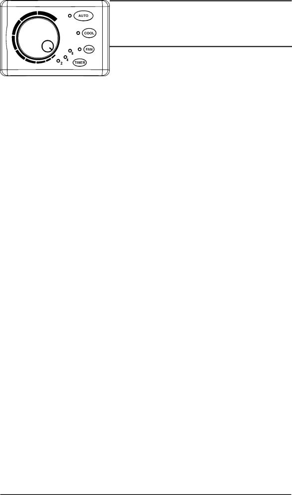
PROGRAMMABLE THERMOSTAT CONTROL
The Programmable Thermostat controller has two modes, MANUAL or AUTOMATIC. In addition it has a TIMER, which will operate in either mode.
Manual Operation
Fan Only
Pressing the FAN button once will turn on the green fanlight and will start the fan only. The variable speed dial will vary the speed of the fan. 
Fan & Pump
Pressing the COOL button once will turn on the green cool light and will start the fan and pump. The variable speed dial will vary the speed of the fan.
*NOTE: When the COOL button is pressed there may be a two or three minute delay in start up if PRE-FILL, or PRE-COOL has been selected in the set up of the controller. This is indicated by a flashing green light next to the COOL button or AUTO button. For more information on these features contact your nearest Climate Technologies dealer or from place of purchase.
Turning off Unit
To switch the unit off, press the button that has the green light. This light will then go out to indicate the unit is off.
Ventilation
On days of high humidity, your unit may operate more efficiently in ventilation mode. To start the FAN ONLY press the fan button.
Use the dial to control the comfort level required (speed of the fan).
Automatic Operation
•To select AUTOMATIC mode press the AUTO button. The green light will be on to indicate that the unit is in the auto mode.
•To select the desired comfort level use the dial  . The dial does not control the speed of the fan this is done automatically by the controller.
Note: The comfort level is individual to each situation and location. Some trial and error may be required to set the dial to your desired comfort level; a good starting point is to have the dial set at the Nine o'clock position. Once the unit has been set, the fan speed and pump are controlled automatically. The unit can be left and will cycle on and off to keep the area being cooled to the set comfort level.
•Around the edge of the dial there is a marking, for more cooling turn the dial clockwise to where the marking increases in size. If the room temperature is too cold turn the dial anti-clockwise for less cooling (a warmer comfort setting).
TEK600 SERIES CONTROL |
Page 8 |

OWNER’S MANUAL
Controls Operation
The Timer
The timer function operates either in Automatic or Manual modes and is designed to switch the unit ON or OFF in a pre-set period (two, four or eight hours).
Note: Once the time function has activated or deactived the unit, it will remain in this mode until another selection has been made at the wall control.
Timer ON
•To switch the unit ON in a pre-set time, firstly select FAN, COOL, or AUTO. Adjust
the dial to your selected position. Press the same button again to turn the unit back to the off mode.
•Select the desired time to switch the unit back on in two, four, or eight hours by pressing the TIMER button until your selected time appears which is indicated by the green light.
•The option that has been selected will begin to flash rapidly. This is indicating to the user that the mode selected will start in the selected time.
•If the owner wants to start the unit instead of waiting for the timer, press the button that the green light is flashing once then press the same button once more to start the unit. This can be indicated by the green light coming on near the button selected.
*NOTE: Repeated TIMER button presses selects the desired time and also disables the timer. The green lights near the two, four, or eight-hour time selections must be illuminated else the timer is in the disabled mode.
Timer OFF
•The timer off mode will switch off the unit in the selected two, four, or eight hours.
•While the unit is running press the TIMER button to select the two, four, or eighthour time option.
•Once the time mode has been selected the unit will turn off in the selected time period and remain in the off mode until pressing one of the function buttons (FAN, COOL, OR AUTO) to restart it.
*NOTE: Repeated TIMER button presses selects the desired time and also disables the timer. The green lights near the two, four, or eight-hour time selections must be illuminated else the timer is in the disabled mode.
TEK600 SERIES CONTROL |
Page 9 |
Loading...