

Reference Manual
S63TU4 ENGINE
Technical Training
The information contained in this manual is not to be resold, bartered, copied or transferred
without the express written consent of BMW of North America, LLC ("BMW NA").
Copyright © 2019 BMW of North America, LLC
Technical�training.
Product�information.
S63TU4�Engine.
BMW�Service

General�information
Symbols�used
The�following�symbol�is�used�in�this�document�to�facilitate�better�comprehension�or�to�draw�attention
to�very�important�information:
Contains�important�safety�information�and�information�that�needs�to�be�observed�strictly�in�order�to
guarantee�the�smooth�operation�of�the�system.
Information�status:�July�2019
BMW�Group�vehicles�meet�the�requirements�of�the�highest�safety�and�quality�standards.�Changes
in�requirements�for�environmental�protection,�customer�benefits�and�design�render�necessary
continuous�development�of�systems�and�components.�Consequently,�there�may�be�discrepancies
between�the�contents�of�this�document�and�the�vehicles�available�in�the�training�course.
The�information�contained�in�the�training�course�materials�is�solely�intended�for�participants�in�this
training�course�conducted�by�BMW�Group�Technical�Training�Centers,�or�BMW�Group�Contract
Training�Facilities.
This�training�manual�or�any�attached�publication�is�not�intended�to�be�a�complete�and�all�inclusive
source�for�repair�and�maintenance�data.�It�is�only�part�of�a�training�information�system�designed�to
assure�that�uniform�procedures�and�information�are�presented�to�all�participants.
For�changes/additions�to�the�technical�data,�repair�procedures,�please�refer�to�the�current�information
issued�by�BMW�of�North�America,�LLC,�Technical�Service�Department.
This�information�is�available�by�accessing�TIS�at�www.bmwcenternet.com.
Additional�sources�of�information
Further�information�on�the�individual�topics�can�be�found�in�the�following:
• Owner's�Manual
• Integrated�Service�Technical�Application
• Aftersales�Information�Research�(AIR)
The�information�contained�in�this�manual�is�not�to�be�resold,�bartered,�copied,�or�transferred
without�the�express�written�consent�of�BMW�of�North�America,�LLC�(“BMW�NA”).
©2019�BMW�of�North�America,�LLC
The�BMW�name�and�logo�are�registered�trademarks.�All�rights�reserved.

S63TU4�Engine.
Contents.
1. Introduction............................................................................................................................................................................................................................................1
1.1. Technical� data............................................................................................................................................................................................................. 1
1.2. Full�load�diagram.................................................................................................................................................................................................... 3
2. Engine�History................................................................................................................................................................................................................................... 4
3. Engine�Identification............................................................................................................................................................................................................. 5
3.1. Engine�identification......................................................................................................................................................................................... 5
3.2. Engine�number.......................................................................................................................................................................................................... 5
4. Engine�Mechanics......................................................................................................................................................................................................................6
4.1. Crankcase...........................................................................................................................................................................................................................6
4.2. Crankshaft�drive....................................................................................................................................................................................................... 7
4.3. Cylinder�head............................................................................................................................................................................................................... 9
4.4. Cylinder�head�cover.......................................................................................................................................................................................12
5. Oil�Supply..............................................................................................................................................................................................................................................13
5.1. Differences�in� the�oil�supply............................................................................................................................................................ 13
5.2. Oil�supply�adaptations...............................................................................................................................................................................13
5.3. Oil�pump.......................................................................................................................................................................................................................... 14
5.3.1. Maximum�delivery........................................................................................................................................................... 17
5.3.2. Minimum�delivery.............................................................................................................................................................19
5.3.3. Second-level�control�(emergency�operation).......................................................................21
5.4. Map�control�valve.............................................................................................................................................................................................. 21
5.5. Oil�supply�during�high�acceleration...................................................................................................................................... 23
5.6. Oil�spray�nozzles/piston�crown�cooling.......................................................................................................................... 25
5.7. Service�information.........................................................................................................................................................................................27
6. Exhaust�Turbocharger.................................................................................................................................................................................................... 29
6.1. Charging�pressure�control.................................................................................................................................................................. 30
7. Exhaust�Emission�Systems..................................................................................................................................................................................32
8. Intake�Air�System...................................................................................................................................................................................................................33
8.1. Air�duct...............................................................................................................................................................................................................................33
8.2. Air�mass�determination............................................................................................................................................................................34
8.3. Crankcase�ventilation/tank�ventilation.............................................................................................................................. 34
9. Fuel�Preparation........................................................................................................................................................................................................................37
9.1. Low-pressure�fuel�system...................................................................................................................................................................37
9.2. High-pressure�fuel�system................................................................................................................................................................. 37
10. Cooling....................................................................................................................................................................................................................................................... 39

S63TU4�Engine.
Contents.
10.1. Charge�air�cooler................................................................................................................................................................................................39
11. Engine�Electrical�System.........................................................................................................................................................................................40
11.1. DME�1�control�unit..........................................................................................................................................................................................42
11.2. DME�2�control�unit..........................................................................................................................................................................................45
S63TU4�Engine.
1.�Introduction.
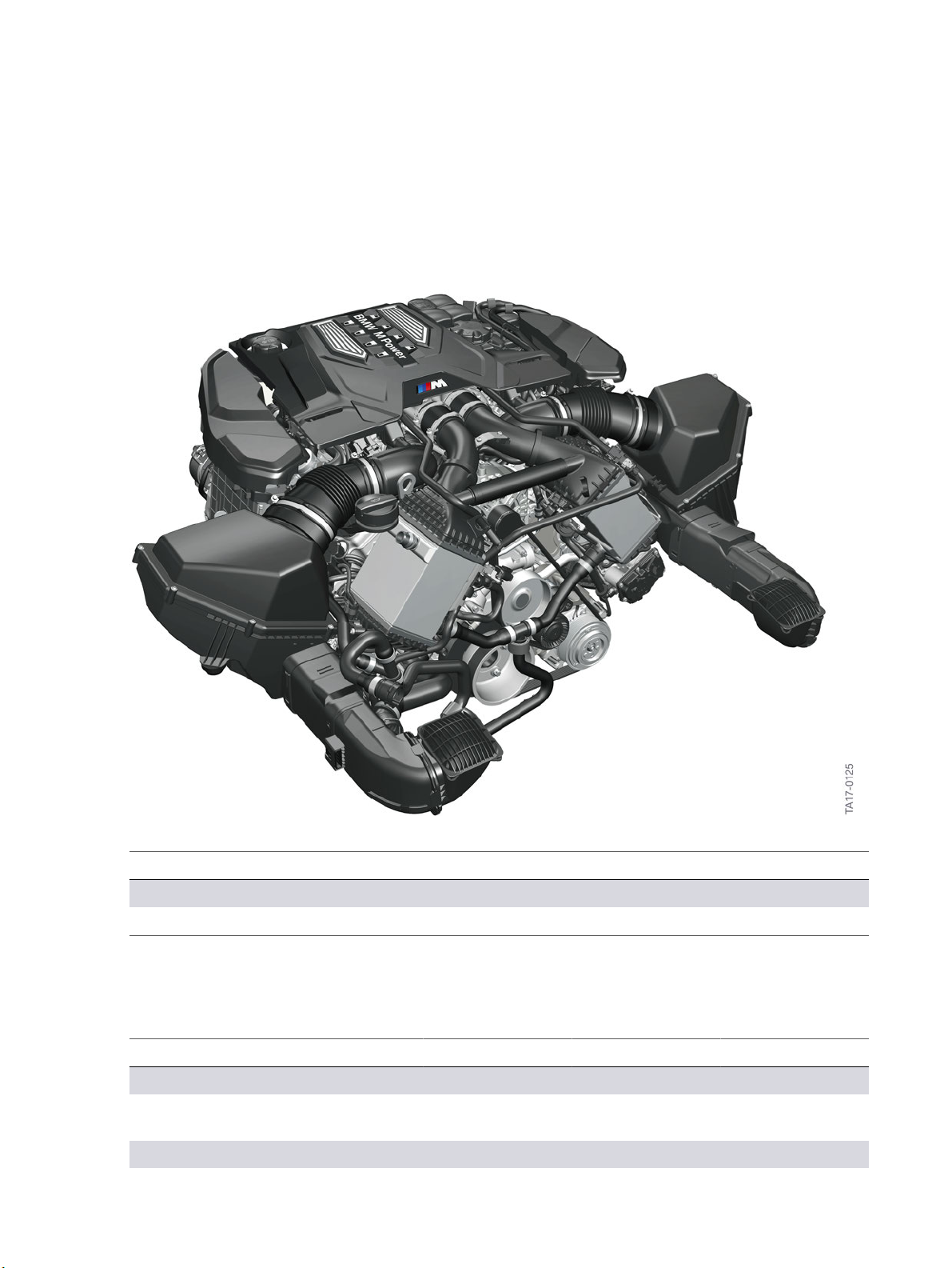
The�S63B44T4�engine�is�the�powerplant�for�various�M�vehicles�and�has�been�taken�over�to�a�large
extent�from�the�F90.�It�is�an�advancement�of�the�S63B44T2�engine�and�technically�based�on�the
N63TU3�engine�(N63B44T3).
This�document�describes�only�the�differences�to�the�S63TU2�engine�(S63B44T2).
S63B44T4�engine
Model�designation Engine�designation Use
BMW�M5 S63B44T4 11/2017
BMW�M8 S63B44T4 07/2019
1.1.�Technical�data
Unit S63B44T0 S63B44T2 S63B44T4
Series F1x/F06 F85/F86 F90/F91/F92
Model�designation BMW�M5/M6 BMW�X5�M
BMW�X6�M
Design V8 V8 V8
BMW�M5
BMW�M8
1

S63TU4�Engine.
1.�Introduction.
Unit S63B44T0 S63B44T2 S63B44T4
Displacement [cc] 4395 4395 4395
Firing�order 1-5-4-8-6-3-7-2 1-5-4-8-6-3-7-2 1-5-4-8-6-3-7-2
Bore�hole/Stroke [mm] 89/88.3 89/88.3 89/88.3
Power
at�engine�speed
Redline [rpm] 7200 6800 7200
Power�output�per�liter [hp/l] 125.6 129.0 134.5
Torque
at�speed
Compression�ratio [ε] 10.0 10.0 10.0
Valves�per�cylinder 4 4 4
Fuel�rating [RON�(AKI)] 98�(93) 98�(93) 98�(93)
Fuel [RON�(AKI)] 95-98�(91–93) 95-98�(91–93) 91-98�(87–93)
Digital�Motor
Electronics
Maximum�speed [mph] 155�(190*) 155�(173*) 155�(190*)
*�Only�in�conjunction�with�M�Driver´s�package�SA�7ME
**�Only�in�conjunction�with�Competition�package�SA�7MA.
[hp]
[rpm]
[ft�lb]
[rpm]
553
567**
6000-7000
501
1500-5750
1500-6000**
MEVD17.2.H MEVD17.2.H DME�8.8T.0
567
6000-6500
553
2200-5000
591
617**
6000
140.4**
553
1800-5600
1800-5860**
2
S63TU4�Engine.
1.�Introduction.
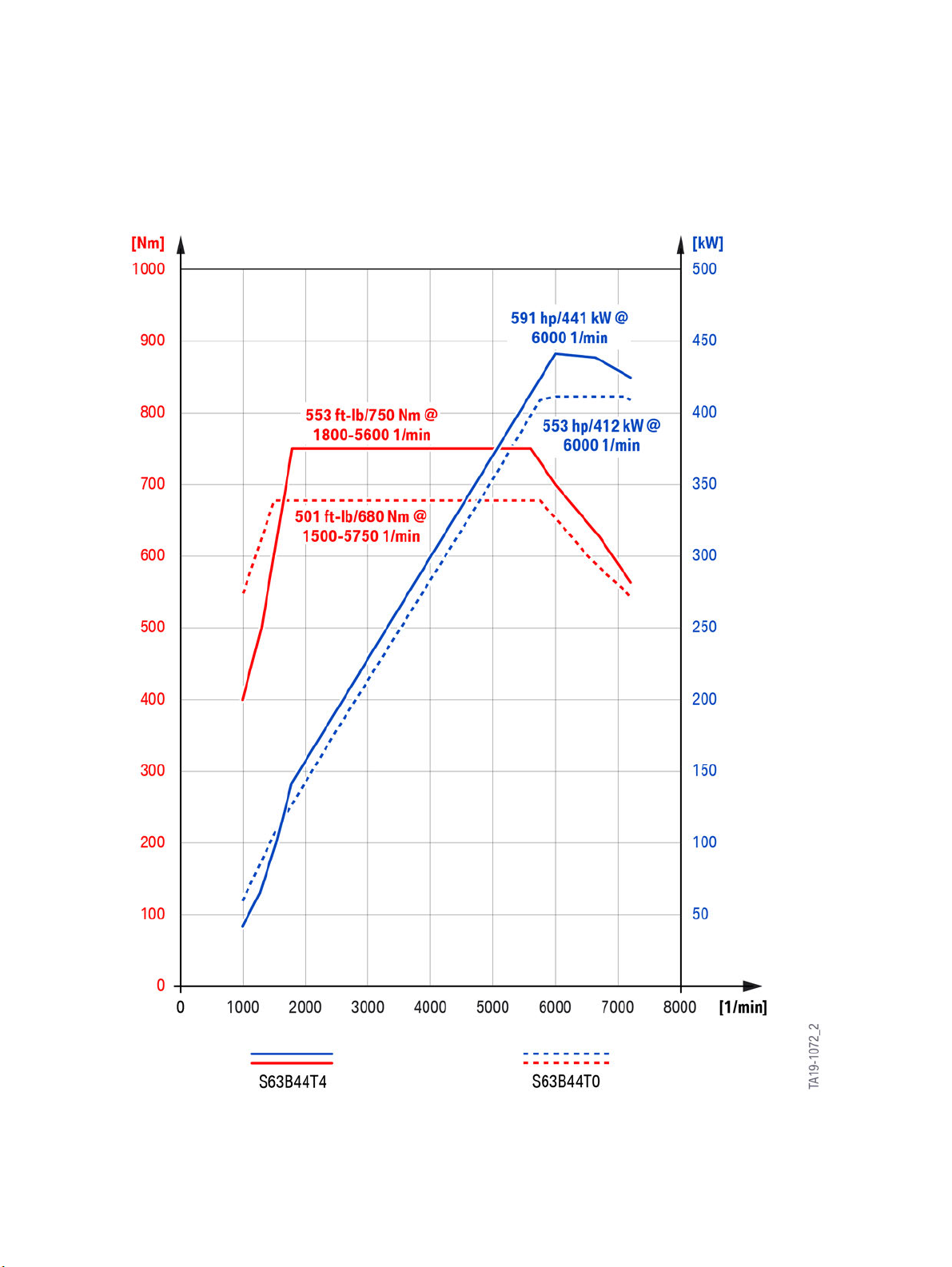
1.2.�Full�load�diagram
S63B44T4�engine,�full�load�diagram
3

S63TU4�Engine.
2.�Engine�History.
Overview�of�S63�engines�at�BMW�M�GmbH.
Engine Model Series Displacement
in�cc
S63B44O0 BMW�X5M/
X6M
S63B44T0 BMW�M5 F10 4395 553 501 2011
S63B44T0 BMW�M6 F12/F13 4395 553 501 2012
S63B44T0
S63B44T0
S63B44T0 BMW�M6 F06 4395 553 501 2013
S63B44T0
S63B44T0
S63B44T0
S63B44T0
BMW�M6
Competition
BMW�M5
Competition
BMW�M6
Competition
BMW�M5
"30�Years
M5"
BMW�M6
Competition
BMW�M6
Competition
E70/E71 4395 547 442 2010
F12/F13 4395 567 501 2012
F10 4395 567 501 2013
F06 4395 567 501 2013
F10 4395 591 516 2014
F12/F13 4395 591 516 2015
F06 4395 591 516 2015
Power
output
in�hp
Torque
in�ft�lb
Used�as�of
S63B44T2 BMW�X5M/
X6M
S63B44T4 BMW�M5 F90 4395 591 553 2017
S63B44T4
BMW�M5
Competition
F85/F86 4395 567 553 2015
F90 4395 617 553 2018
4

S63TU4�Engine.
3.�Engine�Identification.
3.1.�Engine�identification
The�engine�identification�is�used�in�the�technical�documentation�in�order�to�clearly�identify�the�engine.
There�is�no�engine�with�the�designation�S63B44T3�at�BMW�M�GmbH.
Index Explanation
S BMW�Group�"M�GmbH"
6 V8�engine
3 Engine�with�exhaust�turbocharger,�Valvetronic�and�direct�fuel�injection�(TVDI)
B Gasoline�engine�installed�longitudinally
44 4.4�l�displacement
T Top�performance�class
4 Fourth�redesign
The�engines�have�an�identification�mark�on�the�crankcase�to�ensure�unmistakable�identification�and
classification.�This�engine�identification�is�necessary�for�approval�by�government�authorities.�The�first
six�digits�of�the�engine�identification�correspond�to�the�engine�designation.
3.2.�Engine�number
The�engine�number�can�be�found�on�the�engine�above�the�engine�identification.�This�consecutive
number,�in�conjunction�with�the�engine�identification,�permits�clear�identification�of�each�individual
engine.
5

S63TU4�Engine.
4.�Engine�Mechanics.
4.1.�Crankcase
The�crankcase�in�the�S63B44T4�engine�was�taken�over�from�the�N63B44O2�engine�and�adapted�to
the�S63B44T4.�As�of�07/2019�the�same�electric�arc�wire�sprayed�cylinder�barrels�that�are�featured�in
the�modular�engines�are�used�in�the�S63B44T4�engine.�Like�its�predecessor�in�the�S63B44T0�engine,
the�closed-deck�crankcase�in�the�S63B44T4�engine�characterized�by�a�double�main�bearing�screw
connection�with�side�wall�connection.
The�crankcase�cast�part�consists�of�the�cylinder�bores�with�electric�arc�wire�sprayed�barrels,�the
bearing�ways�with�the�bore�holes�for�the�crankshaft�and�associated�bearings�and�the�water�jackets�of
the�cylinders.
In�the�V-chamber�of�the�S63B44T4,�the�connections�that�are�used�in�the�N63B44O2�for�the�engine�oil
coolant�heat�exchanger�are�closed.
S63B44T4�engine,�crankcase
Index Explanation
1 Exhaust�turbocharger�oil�supply
2 Closed�connections�of�the�engine�oil�coolant�heat�exchanger
in�the�S63B44T4�engine
The�S63B44T4�engine�features�the�already�familiar,�external�air/engine�oil�heat�exchanger�that�is
installed�in�front�of�the�cooling�module.
6

S63TU4�Engine.
4.�Engine�Mechanics.
The�crankcase�of�the�S63B44T4�engine�has�undergone�further�changes�to�certain�details.�The�most
prominent�change�is�the�additional�screw�connection�for�the�main�bearing�caps�on�the�crankcase.
In�the�S63B44T4�engine,�a�triple�main�bearing�cap�screw�connection�is�used�that�encompasses
the�double�main�bearing�cap�screw�connection�with�side�panel�connection,�already�in�use�in�the
N63B44O2�engine,�and�an�additional�screw�connection�laterally�in�the�crankcase.
S63B44T4�engine,�main�bearing�cap�screw�connection
Index Explanation
1 Lateral�main�bearing�cap�screw�connection
2 Crankcase
3 Main�bearing�cap�screw�connection�with�side�panel�connection
The�additional�screw�connection�was�necessary�to�adapt�the�crankcase�to�the�even�higher�power
output�and�torque�values�of�the�S63B44T4�engine.
4.2.�Crankshaft�drive
The�crankshaft�drive�without�the�pistons�and�bearing�shells�of�the�S63B44T4�engine�has�been�taken
over�entirely�from�the�S63B44T2�engine.�Since�07/2019�the�bearing�shells�have�been�replaced�in�the
S63B44T4�engine.�A�new�material�composition�is�used�for�the�main�bearing�shell.
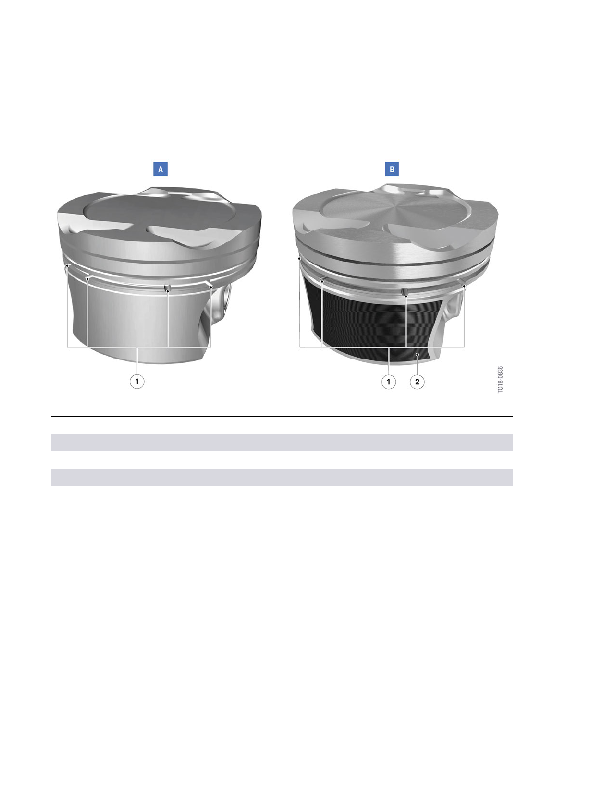
As�of�07/2019�newly�developed�cast�pistons�with�a�graphite�coating�on�the�piston�skirt�are�used�in�the
S63B44T4�engine.�This�is�necessary�because�the�cylinder�barrels�are�electric�arc�wire�sprayed�and
the�pistons�were�therefore�adapted�at�the�same�time.�In�terms�of�the�oil�discharge�concept,�however,
the�pistons�correspond�to�the�pistons�of�the�N63B44T3�engine.�The�shape�of�the�piston�crown�in�the
7
S63TU4�Engine.
4.�Engine�Mechanics.
S63B44T4�engine�was�modified�in�order�to�achieve�a�compression�ratio�of�10:1�in�the�S63B44T4
engine�as�opposed�to�10.5:1�in�the�N63B44T3�engine.�In�addition,�the�piston�crown�was�adapted�for
use�of�the�solenoid�valve�injectors�with�a�fuel�injection�pressure�of�350�bar.
S63B44T4�engine,�piston�comparison
Index Explanation
A S63B44T2�engine,�piston
B S63B44T4�engine,�piston
1 8�oil�drains
2 Graphite�coating�on�piston�skirt
In�order�to�improve�the�oil�drainage�in�the�S63B44T4�engine,�the�piston�was�fitted�with�an�additional
oil�groove�underneath�the�oil�scraper�ring�groove,�as�on�the�N63B44T3�engine.�Together�with�the�8
oil�drains�in�the�piston�skirt,�the�additional�oil�groove�helps�the�drainage�of�oil�pushed�down�by�the�oil
scraper�ring�when�the�piston�moves�down.�This�prevents�the�oil�from�being�carried�past�the�piston
rings,�in�particular�when�the�engine�is�in�coasting�overrun�mode�(during�which�a�vacuum�is�generated
in�the�combustion�chamber).
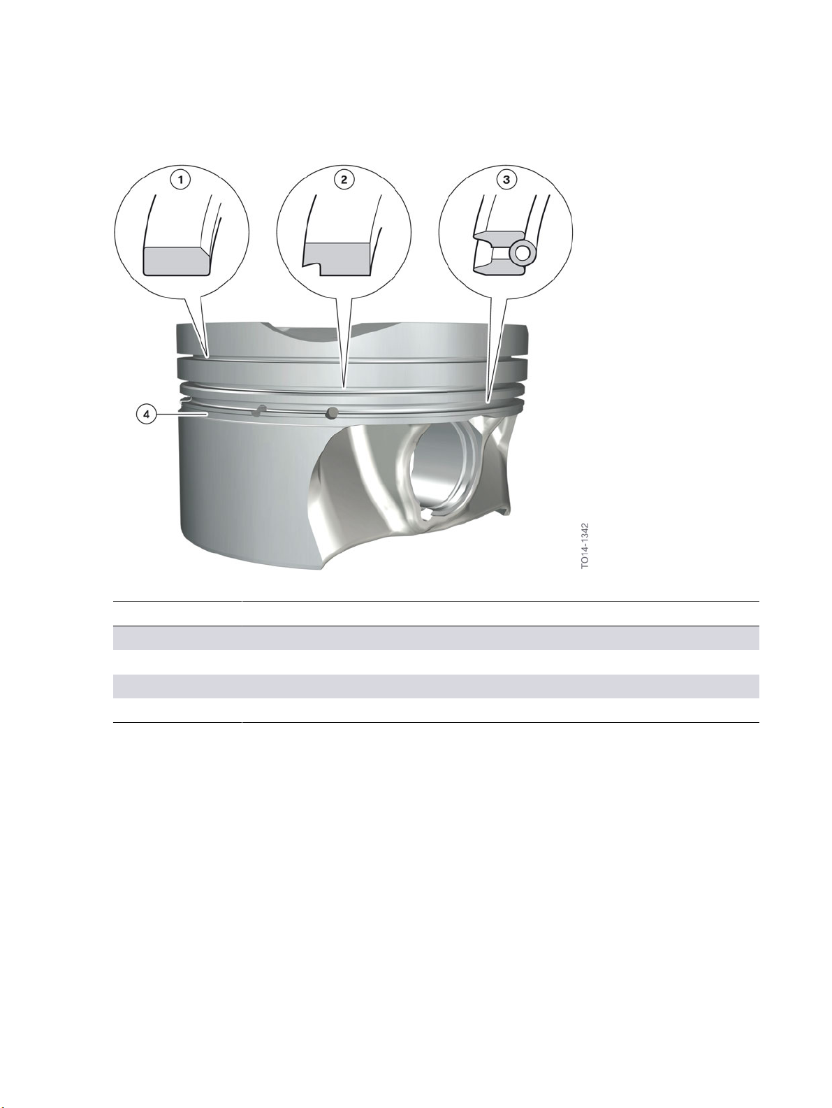
In�terms�of�the�piston�rings,�the�ring�package�from�Federal�Mogul�has�been�used.�The�oil�scraper�ring
in�the�S63B44T4�engine�is�a�"UFlex"�ring�from�Mahle.
8
S63TU4�Engine.
4.�Engine�Mechanics.
S63B44T4�engine,�cast�pistons�with�piston�rings
Index Explanation
1 Plain�rectangular�compression�ring�with�ball-shaped�tire�tread�(B-ring)
2 Taper�faced�piston�ring�(NM-ring)
3 U-ring�with�spiral�expander�(UFlex)
4 Additional�oil�groove
For�further�information�on�the�crankshaft�drive�of�the�S63B44T4�engine,�please�refer�to�the�Product
Information�for�the�“ST1202�S63TU�Engine”.
4.3.�Cylinder�head
The�cylinder�head�of�the�S63B44T4�engine�is�based�on�the�same�concept�as�the�N63B44O2�engine
and�has�the�same�partially�integrated�intake�system.�Thanks�to�this�intake�system�partially�integrated
in�the�cylinder�head,�the�flow�characteristics�of�the�incoming�fresh�gases�have�been�optimized�and�the
space�required�to�install�the�intake�pipe�has�been�significantly�reduced.�Feed-throughs,�such�as�for�the
new�injectors�for�the�HDEV�6,�were�specifically�adapted�to�the�cylinder�head�of�the�S63B44T4�engine.
9

S63TU4�Engine.
4.�Engine�Mechanics.
S63B44T4�engine,�cylinder�head
Index Explanation
1 Sealing�flange�for�intake�system
2 Partially�integrated�intake�pipe
3 Flange�for�Valvetronic�servomotor
4 Cylinder�head,�cylinder�bank�1
The�coolant�flows�in�the�cylinder�head�are�separate�from�the�coolant�flows�in�the�cylinder�jackets.�By
moving�the�VANOS�solenoid�valves�into�the�cylinder�head�cover�and�also�the�VANOS�adjusters�(as�is
already�the�case�for�the�N63B44O2�engine�and�the�modular�engines),�the�bore�holes�for�the�VANOS
solenoid�valves�in�the�cylinder�head�could�be�eliminated,�meaning�that�the�associated�engine�oil�ducts
in�the�cylinder�head�can�also�be�simplified.
Valvetronic�III�technology�is�used�in�the�S63B44T4�engine.�The�Valvetronic�servomotor�is�mounted�on
the�intake�manifold�side�of�the�cylinder�head.
The�combination�of�exhaust�turbocharger,�Valvetronic�and�direct�fuel�injection�is�known�as
Turbo�Valvetronic�Direct�Injection�(TVDI).
10

S63TU4�Engine.
4.�Engine�Mechanics.
S63B44T4�engine,�cylinder�head�with�Valvetronic
Index Explanation
1 VANOS,�exhaust�side
2 Roller�tappet,�high�pressure�pump
3 Eccentric�shaft
4 Spring
5 Gate
6 Intermediate�lever
7 Valvetronic�servomotor
8 VANOS,�intake�side
11
 Loading...