

Page 1
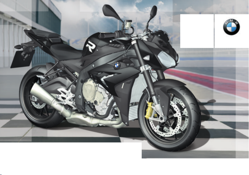
Rider's Manual
S 1000 R
BMW Motorrad
The Ultimate
Riding Machine
Page 2

Vehicle data/dealership details
Vehicle data
Model
Vehicle Identification Number
Colour code
Date of first registration
Registration number
Dealership details
Person to contact in Service department
Ms/Mr
Phone number
Dealership address/phone number (company stamp)
Page 3

Welcome to BMW
We congratulate you on
your choice of a vehicle from
BMW Motorrad and welcome
you to the community of BMW
riders. Familiarise yourself with
your new vehicle so that you can
ride it safely and confidently in all
traffic situations.
About this Rider's Manual
Please read this Rider's Manual
carefully before starting to use
your new BMW. It contains important information on how to
operate the controls and how to
make the best possible use of all
your BMW's technical features.
In addition, it contains information on maintenance and care to
help you maintain your vehicle's
reliability and safety, as well as its
value.
Suggestions and criticism
If you have questions concerning
your motorcycle, your authorised
BMW Motorrad dealer will gladly
provide advice and assistance.
We hope you will enjoy riding
your BMW and that all your journeys will be pleasant and safe
BMW Motorrad.
01 41 8 565 351
*01418565351*
Page 4

Table of Contents
1 General instructions ... . 5
Overview . . . . . . . . . . . . . . . . . . . . . 6
Abbreviations and
symbols . . . . . . . . . . . . . . . . . . . . . . 6
Equipment . . . . . . . . . . . . . . . . . . . 7
Technical data . . . . . . . . . . . . . . . 7
Actuality . . . . . . . . . . . . . . . . . . . . . . 7
2 General views . .. .. .. .. .. . 9
General view, left side . . . . . . . 11
General view, left side, with
DDC . . . . . . . . . . . . . . . . . . . . . . . . 13
General view, right side . . . . . 15
Underneath the seat . . . . . . . . 16
Multifunction switch, left .. . . 17
Multifunction switch,
right . . . . . . . . . . . . . . . . . . . . . . . . . 18
Instrument panel . . . . . . . . . . . . 19
3 Status indicators ... .. .. 21
Warning and telltale
lights . . . . . . . . . . . . . . . . . . . . . . . . 22
Multifunction display . . . . . . . . 24
Warnings . . . . . . . . . . . . . . . . . . . . 25
Fuel down to reserve . . . . . . . . 36
Range . . . . . . . . . . . . . . . . . . . . . . . 37
Service-due indicator . . . . . . . . 37
4 Operation .. .. .. .. .. .. .. .. 39
Ignition switch/steering
lock . . . . . . . . . . . . . . . . . . . . . . . . . 40
Ignition . . . . . . . . . . . . . . . . . . . . . . 40
Electronic immobiliser
EWS . . . . . . . . . . . . . . . . . . . . . . . . 41
Multifunction display . . . . . . . . 42
Anti-theft alarm (DWA) . . . . . . 46
Headlight . . . . . . . . . . . . . . . . . . . . 48
Lights . . . . . . . . . . . . . . . . . . . . . . . 48
Turn indicators . . . . . . . . . . . . . . 49
Hazard warning flashers . . . . . 49
Emergency off switch (kill
switch) . . . . . . . . . . . . . . . . . . . . . . 50
BMW Motorrad Race
ABS . . . . . . . . . . . . . . . . . . . . . . . . . 50
BMW Motorrad ASC . . . . . . . 52
Dynamic Traction Control
DTC . . . . . . . . . . . . . . . . . . . . . . . . . 53
Riding mode . . . . . . . . . . . . . . . . 54
Cruise-control system . . . . . . . 56
Brakes . . . . . . . . . . . . . . . . . . . . . . 58
Tyres . . . . . . . . . . . . . . . . . . . . . . . . 59
Heated handlebar grips . . . . . 60
Mirrors . . . . . . . . . . . . . . . . . . . . . . 61
Front and rear seats . . . . . . . . . 61
Helmet holder . . . . . . . . . . . . . . . 62
Luggage loops . . . . . . . . . . . . . . 63
5 On the race track .. .. .. . 65
LAPTIMER . . . . . . . . . . . . . . . . . . 66
RACE INFO . . . . . . . . . . . . . . . . . 70
SETUP MENU . . . . . . . . . . . . . . 75
Spring preload .. . . . . . . . . . . . . 78
Damping . . . . . . . . . . . . . . . . . . . . 81
Removing/installing mir-
rors. . . . . . . . . . . . . . . . . . . . . . . . . . 85
Removing and installing
number-plate carrier. . . . . . . . . 86
Removing and installing front
turn indicators . . . . . . . . . . . . . . . 89
6 Riding .. .. .. .. .. ... ... ... . 91
Safety instructions .. . . . . . . . . 92
Comply with checklist . . . . . . . 94
Starting. . . . . . . . . . . . . . . . . . . . . . 94
Page 5

Running in .. . . . . . . . . . . . . . . . . 98
Shifting gear .. . . . . . . . . . . . . . . 99
Brakes . . . . . . . . . . . . . . . . . . . . 101
Parking your motor-
cycle . . . . . . . . . . . . . . . . . . . . . . 102
Refuelling . . . . . . . . . . . . . . . . . 103
Securing motorcycle for
transportation . . . . . . . . . . . . . 105
7 Engineering
details . .. .. .. .. . .. .. .. . 107
Riding mode . . . . . . . . . . . . . . 108
Mode changes . . . . . . . . . . . . 110
Brake system with
BMW Motorrad Race
ABS . . . . . . . . . . . . . . . . . . . . . . . 110
Electronic engine management with BMW Motorrad
ASC . . . . . . . . . . . . . . . . . . . . . . . 113
Engine management with
Dynamic Traction Con-
trol . . . . . . . . . . . . . . . . . . . . . . . . 114
Dynamic Damping Con-
trol . . . . . . . . . . . . . . . . . . . . . . . . 115
8 Accessories . .. .. .. . .. . 117
General instructions . . . . . . . 118
Luggage .. . . . . . . . . . . . . . . . . 118
9 Maintenance . . . .. .. .. . 121
General instructions . . . . . . . 122
Toolkit. . . . . . . . . . . . . . . . . . . . . 122
Rear-wheel stand . . . . . . . . . 123
Front-wheel stand . . . . . . . . . 124
Engine oil . . . . . . . . . . . . . . . . . 126
Brake system .. . . . . . . . . . . . 127
Coolant. . . . . . . . . . . . . . . . . . . . 132
Body panels . . . . . . . . . . . . . . . 133
Clutch . . . . . . . . . . . . . . . . . . . . . 136
Chain . . . . . . . . . . . . . . . . . . . . . . 137
Wheels . . . . . . . . . . . . . . . . . . . . 139
Lighting . . . . . . . . . . . . . . . . . . . 148
Fuses . . . . . . . . . . . . . . . . . . . . . 156
Jump-starting . . . . . . . . . . . . . 157
Battery . . . . . . . . . . . . . . . . . . . . 158
10 Care . . .. .. .. .. .. .. . .. . 161
Care products . . . . . . . . . . . . . 162
Washing the vehicle . . . . . . . 162
Cleaning easily damaged
components . . . . . . . . . . . . . . . 163
Paint care . . . . . . . . . . . . . . . . . 164
Laying up the motor-
cycle . . . . . . . . . . . . . . . . . . . . . . 164
Protective wax coating . . . . 164
Restoring motorcycle to
use . . . . . . . . . . . . . . . . . . . . . . . . 165
11 Technical data . . .. .. 167
Troubleshooting chart . . . . . 168
Threaded fasteners . . . . . . . 169
Engine . . . . . . . . . . . . . . . . . . . . 171
Fuel . . . . . . . . . . . . . . . . . . . . . . . 172
Engine oil . . . . . . . . . . . . . . . . . 172
Clutch . . . . . . . . . . . . . . . . . . . . . 173
Transmission . . . . . . . . . . . . . . 173
Rear-wheel drive . . . . . . . . . . 174
Running gear . . . . . . . . . . . . . . 174
Brakes . . . . . . . . . . . . . . . . . . . . 175
Wheels and tyres . . . . . . . . . . 175
Electrics . . . . . . . . . . . . . . . . . . . 177
Frame . . . . . . . . . . . . . . . . . . . . . 179
Dimensions .. . . . . . . . . . . . . . 179
Weights . . . . . . . . . . . . . . . . . . . 180
Riding specifications . . . . . . 180
Page 6

12 Service . . .. .. .. . .. .. .. 181
BMW Motorrad Service . . . 182
BMW Motorrad Mobility
services . . . . . . . . . . . . . . . . . . . 182
Maintenance work . . . . . . . . . 182
Maintenance schedule . . . . 185
Standard BMW service . . . . 186
Confirmation of mainten-
ance work . . . . . . . . . . . . . . . . . 187
Confirmation of service . . . . 192
13 Appendix . .. .. .. .. .. . . 195
Certificate for electronic
immobiliser . . . . . . . . . . . . . . . . 196
14 Index . .. .. .. .. .. .. .. .. 198
Page 7

General instructions
Overview . . . . . . . . . . . . . . . . . . . . . . . . . . . . 6
Abbreviations and symbols . . . . . . . . . . 6
Equipment . . . . . . . . . . . . . . . . . . . . . . . . . . . 7
Technical data . . . . . . . . . . . . . . . . . . . . . . . 7
Actuality . . . . . . . . . . . . . . . . . . . . . . . . . . . . . 7
1
5
z
General instructions
Page 8
Overview
1
Chapter 2 of this Rider's Manual
will provide you with an initial
6
overview of your motorcycle. All
maintenance and repair work on
the motorcycle is documented in
Chapter 12. This record of the
maintenance work you have had
performed on your vehicle is a
precondition for generous treatment of goodwill claims.
When the time comes to sell
your BMW, please remember
to hand over this Rider's Manual;
it is an important part of the motorcycle.
z
General instructions
Abbreviations and symbols
CAUTION Low-risk hazard.
Non-avoidance can lead to
slight or moderate injury.
WARNING Medium-risk
hazard. Non-avoidance can
lead to fatal or severe injury.
DANGER High-risk hazard. Non-avoidance leads
to fatal or severe injury.
ATTENTION Special
notes and precautionary
measures. Non-compliance can
lead to damage to the vehicle or
accessory and, consequently, to
voiding of the warranty.
NOTICE Specific instruc-
tions on how to operate,
control, adjust or look after items
of equipment on the vehicle.
Indicates the end of an
item of information.
Instruction.
Result of an activity.
Reference to a page with
more detailed information.
Indicates the end of a
passage relating to specific accessories or items
of equipment.
Tightening torque.
Technical data.
Anti-lock brake system.
ABS
ASC Automatic Stability Con-
trol.
DDC Dynamic Damping Con-
trol.
DTC Dynamic Traction Con-
trol.
Page 9

DWA
Anti-theft alarm (Diebstahlwarnanlage).
Electronic immobiliser.
EWS
VDS Vertical Down Sensor
(drop sensor)
OE Optional extras.
The vehicles are assembled complete with
all the BMW Motorrad
optional extras originally
ordered.
OA Optional accessories.
You can obtain
BMW Motorrad
optional accessories
through your authorised
BMW Motorrad dealer;
optional accessories
have to be retrofitted to
the vehicle.
Equipment
When you purchased your BMW
motorcycle, you chose a model
with individual equipment. This
Rider's Manual describes the
optional extras (OE) offered by
BMW and selected optional accessories (OA). This explains why
the manual may also contain descriptions of equipment which
you have not ordered. Please
note, too, that your motorcycle
might not be exactly as illustrated in this manual on account
of country-specific differences.
If your motorcycle contains
equipment that has not been
described, its description can be
found in a separate manual.
Technical data
All dimensions, weights and
power ratings stated in the
Rider's Manual are quoted to the
standards and comply with the
tolerance requirements of the
Deutsches Institut für Normung
e.V. (DIN). Versions for individual
countries may differ.
Actuality
The high safety and quality level
of BMW motorcycles is ensured
by continuous development
work on design, equipment
and accessories. Because of
this, your motorcycle may differ
from the information supplied
in the Rider's Manual. Nor can
BMW Motorrad entirely rule
out errors and omissions. We
hope you will appreciate that no
claims can be entertained on the
basis of the data, illustrations or
descriptions in this manual.
1
7
z
General instructions
Page 10

1
8
z
General instructions
Page 11

General views
General view, left side . . . . . . . . . . . . . . . 11
General view, left side, with DDC . . . 13
General view, right side . . . . . . . . . . . . . 15
Underneath the seat . . . . . . . . . . . . . . . . 16
Multifunction switch, left . . . . . . . . . . . . 17
Multifunction switch, right . . . . . . . . . . . 18
Instrument panel . . . . . . . . . . . . . . . . . . . . 19
2
9
z
General views
Page 12
2
10
z
General views
Page 13

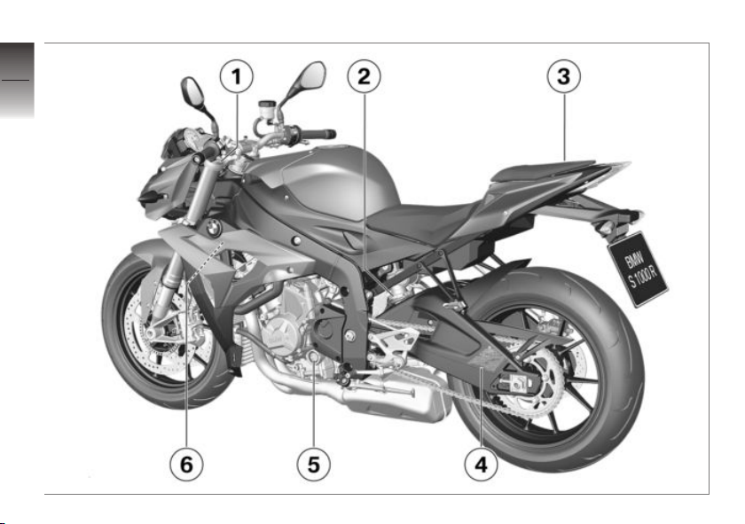
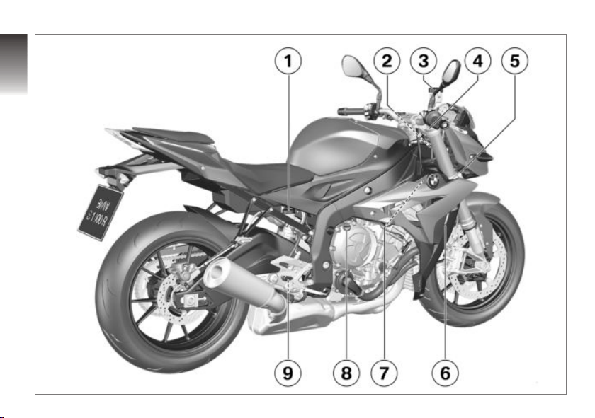
General view, left side
1 Adjuster for front
compression-stage
damping (red scale)
( 82)
2 Adjuster for spring preload,
rear ( 78)
3 Seat lock ( 61)
4 Table of tyre pressures
Payload table
Chain settings
5 Engine oil level indicator
( 126)
6 OA connector for naviga-
tion system
2
11
z
General views
Page 14
2
12
z
General views
Page 15

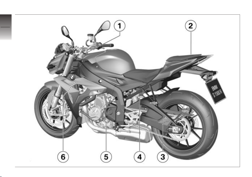
General view, left side, with DDC
with Dynamic Damping Control
OE
(DDC)
1 Adjusting spring preload
for front wheel ( 80).
2 Seat lock ( 61)
3 Table of tyre pressures
Payload table
Chain settings
4 Adjuster for spring preload,
rear ( 79)
5 Engine oil level indicator
( 126)
6 OA connector for naviga-
tion system
2
13
z
General views
Page 16
2
14
z
General views
Page 17

General view, right side
1 Brake-fluid reservoir, rear
( 131)
2 Vehicle identification num-
ber (VIN) and type plate
(on steering-head bearing)
3 Brake-fluid reservoir, front
( 130)
4 Adjuster for front rebound-
stage damping (yellow
scale) ( 82)
5 Steering damper
6 Coolant-level indicator
( 132)
7 OA connector
8 Oil filler neck ( 127)
9 Adjuster for rear rebound-
stage damping (low on
spring strut; yellow scale)
( 83)
2
15
z
General views
Page 18
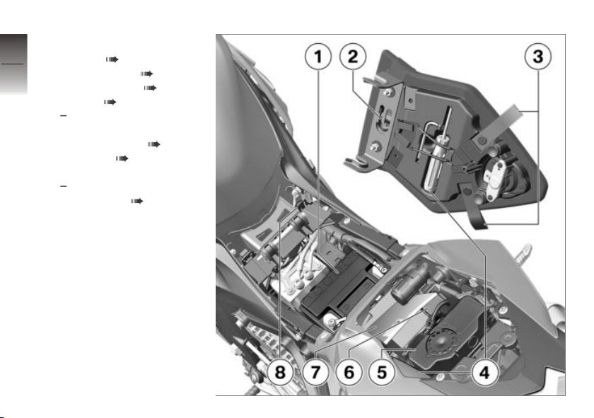
Underneath the seat
2
1 Battery ( 158)
2 Helmet holder ( 62)
16
3 Luggage loops ( 63)
4 Toolkit ( 122)
5 with alarm system
Anti-theft alarm ( 46)
6 Fuse box ( 156)
7 Rider's Manual
8 with Pro riding modes
Coding plug ( 56)
z
General views
(DWA)
OE
OE
Page 19
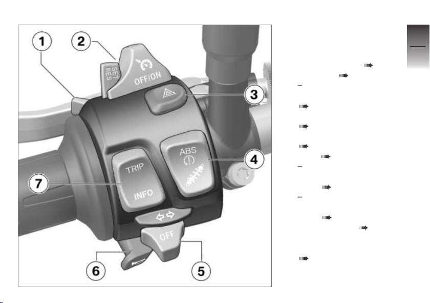
Multifunction switch, left
1 High-beam headlight and
headlight flasher ( 48)
Lap timer ( 68)
2 with cruise control
Cruise-control system
( 56)
3 Hazard warning flashers
( 49)
4 BMW Motorrad Race ABS
( 50)
ASC ( 52)
with Dynamic Traction
Control (DTC)
DTC ( 53)
with Dynamic Damping
Control (DDC)
DDC ( 85)
5 Turn indicators ( 49)
6 Horn
7 Display-mode selection
( 42)
OE
OE
OE
2
17
z
General views
Page 20

Multifunction switch,
2
right
18
1 with heated handlebar
2 Riding mode ( 54)
3 Emergency off switch (kill
4 Start engine ( 94)
z
General views
OE
grips
Heated handlebar grips
( 60)
switch) ( 50)
Page 21
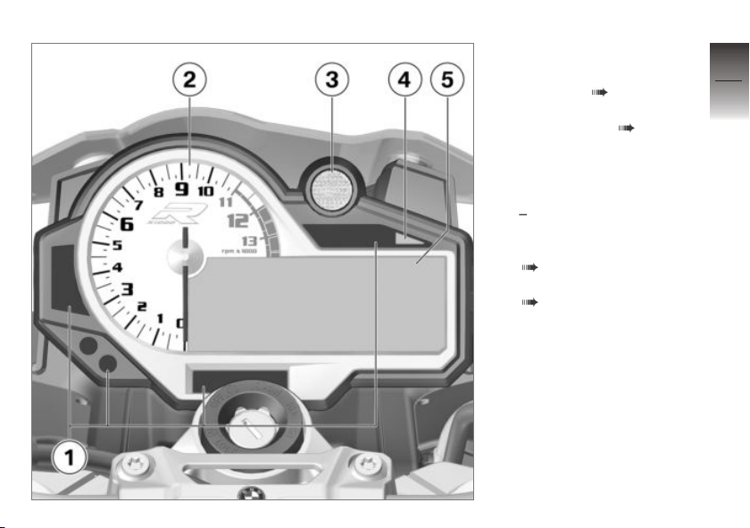
Instrument panel
1 Panels for warning and tell-
tale lights ( 22)
2 Rev. counter
3 Gearshift light ( 99)
4 Ambient-light brightness
sensor (for adapting the
brightness of the instrument lighting)
with alarm system
OE
(DWA)
DWA status indicator light
( 46)
5 Multifunction display
( 24)
2
19
z
General views
Page 22

2
20
z
General views
Page 23

Status indicators
Warning and telltale lights . . . . . . . . . . . 22
Multifunction display . . . . . . . . . . . . . . . . 24
Warnings . . . . . . . . . . . . . . . . . . . . . . . . . . . 25
Fuel down to reserve . . . . . . . . . . . . . . . 36
Range . . . . . . . . . . . . . . . . . . . . . . . . . . . . . . 37
Service-due indicator . . . . . . . . . . . . . . . 37
3
21
z
Status indicators
Page 24
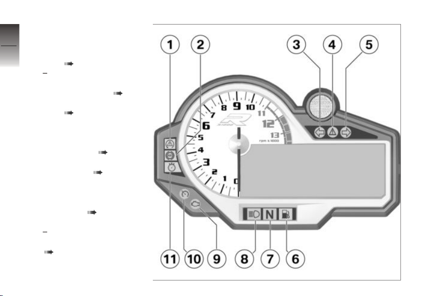
Warning and telltale
3
lights
22
1 ASC telltale and warning
light ( 33)
with Dynamic Traction
Control (DTC)
DTC warning light ( 34)
2 ABS telltale and warning
light ( 32)
3 Turn indicators, left
4 General warning light (in
combination with warnings
in the display) ( 25)
5 Turn indicators, right
6 Fuel reserve ( 36)
z
Status indicators
7 Idle
8 High-beam headlight
9 Warning light for engine
electronics ( 30)
10 Cruise-control system
with cruise control
Switching on cruise control
( 56).
OE
OE
Page 25

11 Light for the fastest lap
( 69)
3
23
z
Status indicators
Page 26
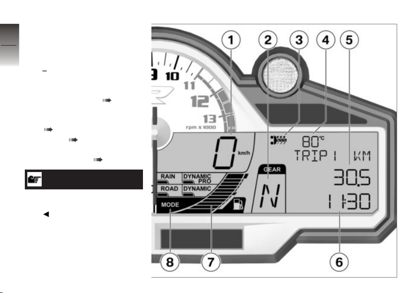
Multifunction display
3
1 Speedometer
2 Gear indicator; "N" indic-
24
z
Status indicators
ates neutral
3 with heated handlebar
4 Coolant temperature
5 General information
6 Clock ( 44)
7 Fuel level
8 Riding mode ( 54)
See Section 5 for information on
the display modes for the race
track.
OE
grips
Operating the heated
handlebar grips ( 60)
( 44)
NOTICE
Page 27
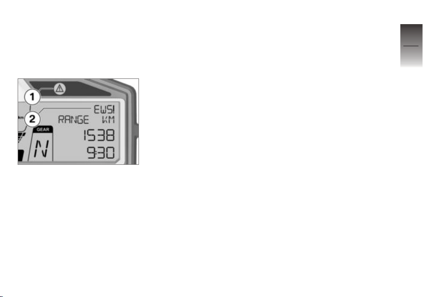
Warnings
Mode of presentation
Warnings are indicated by the
corresponding warning lights.
If two or more warnings occur at
the same time, all the appropriate warning lights and warning
symbols appear, alternating with
warning words as applicable.
The possible warnings are listed
on the next pages.
3
25
Warnings for which there is no
dedicated warning light are indicated by 'General' warning light 1
showing in combination with a
warning such as, for example, 2
appearing on the multifunction
display. The 'general' warning
light shows red or yellow, depending on the urgency of the
warning.
z
Status indicators
Page 28
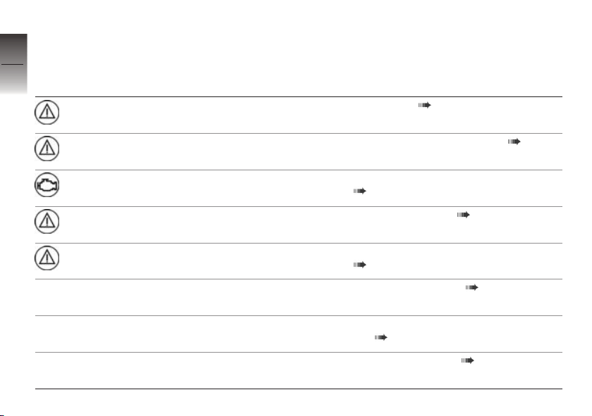
Warnings, overview
3
Warning and telltale
26
lights
lights up yellow
flashes red Coolant-tempera-
lights up Engine in emergency-operation mode
lights up yellow
z
Status indicators
lights up yellow
Warning symbols in the
display
EWS! appears on
the display
ture reading flashes
LAMPR! appears
on the display
LAMPF! appears
on the display
Meaning
EWS active ( 30)
Coolant temperature too high ( 30)
( 30)
Rear light defective ( 31)
Bulbs for front parking light defective
( 31)
Front lights defective ( 31)
LAMP! appears
on the display
VDS! appears on
the blank display
Bulbs for flashing turn indicators defective ( 31)
Motorcycle dropped ( 32)
Page 29
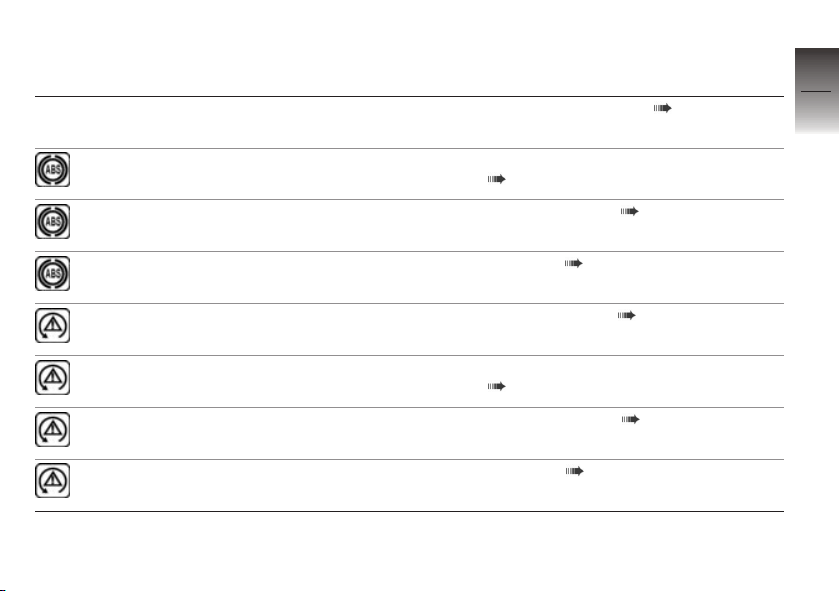
Warning and telltale
lights
flashes ABS self-diagnosis not completed
lights up
Warning symbols in the
display
VDS! appears on
the display
Meaning
Drop sensor defective ( 32)
( 32)
ABS switched off ( 33)
3
27
lights up
quick-flashes ASC intervention ( 33)
slow-flashes ASC self-diagnosis not completed
lights up
lights up
ABS fault ( 33)
( 33)
ASC switched off ( 34)
ASC fault ( 34)
z
Status indicators
Page 30
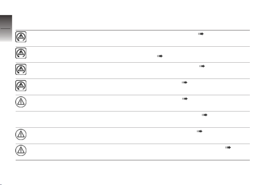
Warning and telltale
3
lights
28
quick-flashes DTC intervention ( 34)
Warning symbols in the
display
Meaning
slow-flashes DTC self-diagnosis not completed
lights up
lights up
lights up yellow
z
Status indicators
lights up yellow
lights up red
DDC! appears on
the display
DWALO! appears
on the display
DWA! appears on
the display
NO CAN appears
on the display
( 34)
DTC switched off ( 35)
DTC fault ( 35)
DDC fault ( 35)
DWA battery weak ( 35)
DWA battery flat ( 36)
CAN open circuit/short circuit ( 36)
Page 31
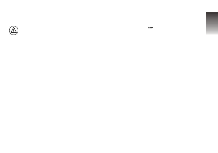
Warning and telltale
lights
lights up yellow
Warning symbols in the
display
NO CODING
appears on the
display
Meaning
No coding ( 36)
3
29
z
Status indicators
Page 32
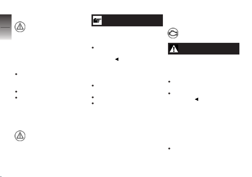
EWS active
3
30
General warning light shows
yellow.
EWS! appears on the display.
Possible cause:
The key being used is not au-
thorised for starting, or communication between key and engine
electronics is disrupted.
Remove all other vehicle keys
from the same ring as the ignition key.
Use the reserve key.
Have the defective key replaced, preferably by an au-
z
Status indicators
thorised BMW Motorrad dealer.
Coolant temperature too
high
General warning light
flashes red.
The coolant-temperature reading
flashes.
ATTENTION
Riding with overheated engine.
Engine damage
Compliance with the
information set out below is
essential.
Possible cause:
The coolant temperature is too
high.
If possible, ride in the part-load
range to cool down the engine.
Check the coolant level.
If the coolant temperature
is frequently too high, have
the fault rectified as soon
as possible by a specialist
workshop, preferably an
authorised BMW Motorrad
dealer.
Engine in emergencyoperation mode
Warning light for engine
electronics shows.
WARNING
Unusual ride characteristics when engine running in
emergency-operation mode.
Risk of accident
Adapt your style of riding accordingly.
Avoid accelerating sharply and
overtaking.
Possible cause:
The engine control unit has dia-
gnosed a fault. In exceptional
cases, the engine stops and refuses to start. Otherwise, the engine runs in emergency operating
mode.
You can continue to ride, but
bear in mind that the usual engine power or the full range of
Page 33
engine rpm might not be available.
Have the fault rectified as
quickly as possible by a
specialist workshop, preferably
an authorised BMW Motorrad
dealer.
Rear light defective
General warning light shows
yellow.
LAMPR! appears on the
display.
Possible cause:
Rear light or brake light bulb defective.
The LED rear light must be
replaced. Consult a specialist
workshop, preferably an authorised BMW Motorrad dealer.
Bulbs for front parking
light defective
General warning light shows
yellow (only if both parking
lights fail).
LAMPF! appears on the
display.
WARNING
Failure of lights on the
vehicle adds to possibility of
other road users overlooking
the vehicle.
Safety risk
Replace defective bulbs as
soon as possible; always carry
a complete set of spare bulbs if
possible.
Possible cause:
Bulb for parking light is defective.
Replacing bulb for left parking
light ( 150).
Replacing parking-light bulb,
right ( 152).
Front lights defective
No indication of a fault if the
high-beam or low-beam headlight fails.
WARNING
Failure of lights on the
vehicle adds to possibility of
other road users overlooking
the vehicle.
Safety risk
Replace defective bulbs as
soon as possible; always carry
a complete set of spare bulbs if
possible.
Possible cause:
Front bulb is defective.
Replacing bulb for low-beam
headlight ( 148).
Replacing bulb for high-beam
headlight ( 150).
Bulbs for flashing turn
indicators defective
LAMP! appears on the display.
3
31
z
Status indicators
Page 34
3
32
z
Status indicators
WARNING
Failure of lights on the
vehicle adds to possibility of
other road users overlooking
the vehicle.
Safety risk
Replace defective bulbs as
soon as possible; always carry
a complete set of spare bulbs if
possible.
Possible cause:
Bulb for turn indicator defective.
Replacing bulbs for front and
rear turn indicators ( 153).
Possible cause:
The number-plate carrier has
been removed; the motorcycle's
on-board electronics know that
the flashing turn indicators are
not installed on the motorcycle.
Installing number-plate carrier
( 87).
NOTICE
If the number-plate carrier is removed in preparation for a racetrack session, the electronics
detect a bulb failure and the
appropriate warning appears
on the display. Activating the
EQIP WARN LAMP function in
the SETUP MENU suppresses
this warning.
Motorcycle dropped
VDS! (Vertical Down Sensor)
appears on the blank display.
Possible cause:
The drop sensor has detected a
drop and has cut out the engine.
Bring the motorcycle to the
upright position
Switch the ignition off and
then on again or switch the kill
switch on and then off again.
Drop sensor defective
VDS! (Vertical Down Sensor)
appears on the display.
Possible cause:
A defect in the drop sensor has
been detected.
Seek the advice of a specialist
workshop, preferably an authorised BMW Motorrad dealer.
ABS self-diagnosis not
completed
ABS telltale and warning
light flashes.
Page 35
Possible cause:
ABS self-diagnosis not
completed
The ABS function is not available, because self-diagnosis
did not complete. (The motorcycle has to reach a defined
minimum speed for the wheel
sensors to be checked: min
5 km/h)
Pull away slowly. Bear in mind
that the ABS function is not
available until self-diagnosis has
completed.
ABS switched off
ABS telltale and warning
light shows.
Possible cause:
The rider has switched off the
ABS system.
Switch on the ABS function
( 51).
ABS fault
ABS telltale and warning
light shows.
Possible cause:
The ABS control unit has detec-
ted a fault. The ABS function is
not available or the functionality
is subject to certain restrictions.
You can continue to ride the
vehicle, but make due provision for the fact that the ABS
function is not available. Bear
in mind the more detailed information on situations that can
lead to an ABS fault ( 112).
Have the fault rectified as
quickly as possible by a
specialist workshop, preferably
an authorised BMW Motorrad
dealer.
ASC intervention
ASC telltale and warning
light quick-flashes.
The ASC control unit has detec-
ted a degree of instability at the
rear wheel and has intervened to
reduce torque. The warning light
flashes for longer than ASC intervention lasts. This affords the
rider visual feedback on control
intervention even after the critical
situation has been dealt with.
ASC self-diagnosis not
completed
ASC telltale and warning
light slow-flashes.
Possible cause:
ASC self-diagnosis not
completed
The ASC function is not available, because self-diagnosis
did not complete. (The motorcycle has to reach a defined
minimum speed with the engine running for the wheelspeed sensors to be checked:
min 5 km/h)
3
33
z
Status indicators
Page 36
Pull away slowly. Bear in mind
that the ASC function is not
3
available until self-diagnosis has
34
completed.
ASC switched off
ASC telltale and warning
light shows.
Possible cause:
The rider has switched off the
ASC system.
Switch on the ASC function
( 52).
ASC fault
z
Status indicators
ASC telltale and warning
light shows.
Possible cause:
The ASC control unit has detec-
ted a fault. Bear in mind that the
ASC function is not available or
the functionality is subject to certain restrictions.
You can continue to ride. Bear
in mind the more detailed in-
formation on situations that can
lead to an ASC fault ( 113).
Have the fault rectified as
quickly as possible by a
specialist workshop, preferably
an authorised BMW Motorrad
dealer.
DTC intervention
with Dynamic Traction Control
OE
(DTC)
DTC warning light quick-
flashes.
The DTC control unit has detected a degree of instability at the
rear wheel and has intervened to
reduce torque. The warning light
flashes for longer than DTC intervention lasts. This affords the
rider visual feedback on control
intervention even after the critical
situation has been dealt with.
DTC self-diagnosis not
completed
with Dynamic Traction Control
OE
(DTC)
DTC warning light slowflashes.
Possible cause:
DTC self-diagnosis not
completed
The DTC function is not available, because self-diagnosis
did not complete. (The motorcycle has to reach a defined
minimum speed with the engine running for the wheelspeed sensors to be checked:
min 5 km/h)
Pull away slowly. Bear in mind
that the DTC function is not
available until self-diagnosis has
completed.
Page 37
DTC switched off
with Dynamic Traction Control
OE
(DTC)
DTC warning light flashes.
Possible cause:
The rider has switched off the
DTC system.
Switch on the DTC function
( 53).
DTC fault
with Dynamic Traction Control
OE
(DTC)
DTC warning light flashes.
Possible cause:
The DTC control unit has detec-
ted a fault. Bear in mind that the
DTC function is not available or
the functionality is subject to certain restrictions.
You can continue to ride. Bear
in mind the more detailed information on situations that can
lead to an DTC fault ( 113).
Have the fault rectified as
quickly as possible by a
specialist workshop, preferably
an authorised BMW Motorrad
dealer.
DDC fault
General warning light shows
yellow.
DDC! appears on the display.
Possible cause:
The DDC control unit has detec-
ted a fault.
Have the fault rectified as
quickly as possible by a
specialist workshop, preferably
an authorised BMW Motorrad
dealer.
In this condition, the motorcycle has too much damping
and is uncomfortable to drive,
especially on roads in poor
condition.
DWA battery weak
with alarm system (DWA)
OE
DWALO! appears on the
display.
NOTICE
This error message shows briefly
only after the Pre-Ride-Check
completes.
Possible cause:
The integral battery in the anti-
theft alarm (DWA) has lost a significant proportion of its original
capacity. There is no assurance
of how long the DWA anti-theft
alarm can remain operational if
the vehicle's battery is disconnected.
Seek the advice of a specialist
workshop, preferably an authorised BMW Motorrad dealer.
3
35
z
Status indicators
Page 38
DWA battery flat
3
with alarm system (DWA)
36
General warning light shows
yellow.
DWA! appears on the display.
NOTICE
This error message shows briefly
only after the Pre-Ride-Check
completes.
Possible cause:
The integral battery in the anti-
theft alarm (DWA) has lost its en-
z
Status indicators
tire original capacity. There is no
assurance that the DWA antitheft alarm will be operational if
the vehicle's battery is disconnected.
Seek the advice of a specialist
workshop, preferably an authorised BMW Motorrad dealer.
OE
CAN open circuit/short
circuit
General warning light shows
red.
NO CAN (Controller Area Net-
work) appears on the display.
Possible cause:
A fault in the Controller Area Network has been detected.
Seek the advice of a specialist
workshop, preferably an authorised BMW Motorrad dealer.
No coding
General warning light shows
yellow.
NO CODING appears on the
display.
Possible cause:
A coding fault has been detected.
The reading remains visible for
10 seconds before disappearing automatically.
Seek the advice of a specialist
workshop, preferably an authorised BMW Motorrad dealer.
Fuel down to reserve
Warning light for fuel down
to reserve shows.
WARNING
Irregular engine operation or
engine shutdown due to lack
of fuel.
Risk of accident. Damage to
catalytic converter.
Do not run the fuel tank dry.
Possible cause:
The fuel tank contains no more
than the reserve quantity of fuel.
Fuel reserve
approx. 4 l
Refuelling ( 103).
Page 39
Range
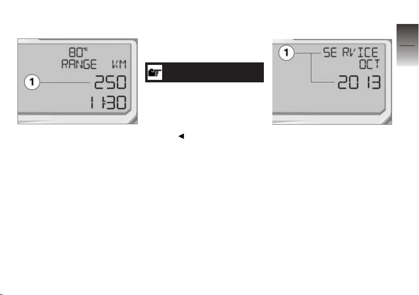
The range readout 1 indicates
how far you can ride with the fuel
remaining in the tank. This distance is calculated on the basis
of fuel level and average consumption.
After a refuelling stop, the distance counter for reserve fuel is
reset if the amount of fuel in the
tank is greater than the reserve
quantity.
When the motorcycle is propped
on its side stand the slight angle
of inclination means that the
sensor cannot register the fuel
level correctly. This is the reason
why the range is calculated only
when the side stand is in the retracted position.
NOTICE
The calculated range is only
an approximate figure. Consequently, BMW Motorrad recommends that you should not
try to use the full range before
refuelling.
Service-due indicator
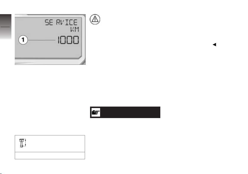
If the next service is due in less
than one month, the date for the
next service 1 is shown briefly
after the Pre-Ride-Check completes. In this example the reading means "October 2013".
3
37
z
Status indicators
Page 40
3
38
If the vehicle covers long distances in the course of the year,
under certain circumstances it
might be necessary to have it
serviced at a date in advance
of the forecast due date. If the
countdown distance to the early
z
Status indicators
service is within the defined displayable range, this countdown
distance 1 appears briefly on the
display after the Pre-Ride-Check
completes.
Maximum countdown
distance to next service:
1000 km
General warning light shows
yellow and SERVICE!
remains permanently visible on
the display.
If service is overdue, the due
date or the odometer reading at
which service was due is accompanied by the 'General' warning
light showing yellow. The word
"Service" remains permanently
visible.
Seek the advice of a specialist
workshop, preferably an authorised BMW Motorrad dealer.
NOTICE
If the service-due indicator appears more than a month before
the service date, the date saved
in the instrument cluster must
be adjusted. This situation can
occur if the battery was discon-
nected for a prolonged period of
time.
If you want to have the date
set consult a specialist workshop, preferably an authorised
BMW Motorrad dealer.
Page 41

Operation
Ignition switch/steering lock . . . . . . . . . 40
Ignition. . . . . . . . . . . . . . . . . . . . . . . . . . . . . . 40
Electronic immobiliser EWS. . . . . . . . . 41
Multifunction display . . . . . . . . . . . . . . . . 42
Anti-theft alarm (DWA) . . . . . . . . . . . . . . 46
Headlight . . . . . . . . . . . . . . . . . . . . . . . . . . . 48
Lights . . . . . . . . . . . . . . . . . . . . . . . . . . . . . . . 48
Turn indicators. . . . . . . . . . . . . . . . . . . . . . 49
Hazard warning flashers. . . . . . . . . . . . . 49
Emergency off switch (kill
switch) . . . . . . . . . . . . . . . . . . . . . . . . . . . . . . 50
BMW Motorrad Race ABS . . . . . . . . . . 50
BMW Motorrad ASC . . . . . . . . . . . . . . . 52
Dynamic Traction Control DTC . . . . . 53
Riding mode . . . . . . . . . . . . . . . . . . . . . . . . 54
Cruise-control system . . . . . . . . . . . . . . 56
Brakes . . . . . . . . . . . . . . . . . . . . . . . . . . . . . . 58
Tyres . . . . . . . . . . . . . . . . . . . . . . . . . . . . . . . 59
Heated handlebar grips . . . . . . . . . . . . . 60
Mirrors . . . . . . . . . . . . . . . . . . . . . . . . . . . . . . 61
Front and rear seats . . . . . . . . . . . . . . . . 61
Helmet holder . . . . . . . . . . . . . . . . . . . . . . 62
Luggage loops . . . . . . . . . . . . . . . . . . . . . . 63
4
39
z
Operation
Page 42
Ignition switch/steering
4
lock
40
Keys
You receive 2 ignition keys.
Consult the information on the
electronic immobiliser (EWS)
( 41) if a key is lost or mislaid.
Ignition
Switching on ignition
One-key system
Ignition switch/steering lock
Tank filler cap
z
Operation
Seat lock
Rear seat cover
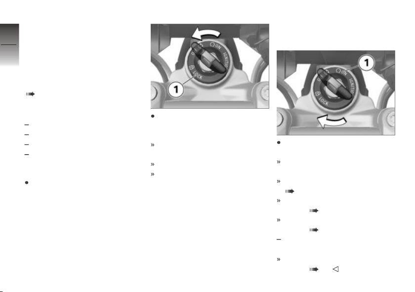
Lock the handlebars
Turn the handlebars to the left
full-lock position.
Turn the key to position 1,
while moving the handlebars
slightly.
Ignition, lights and all function
circuits are switched off.
Handlebars are locked.
Key can be removed.
Insert the key in the ignition
switch and turn to position 1.
Side lights and all function circuits are switched on.
Pre-Ride-Check is performed.
( 95)
ABS self-diagnosis is in progress. ( 96)
ASC self-diagnosis is in progress. ( 97)
with Dynamic Traction Control
OE
(DTC)
DTC self-diagnosis is in pro-
gress. ( 97)
Page 43
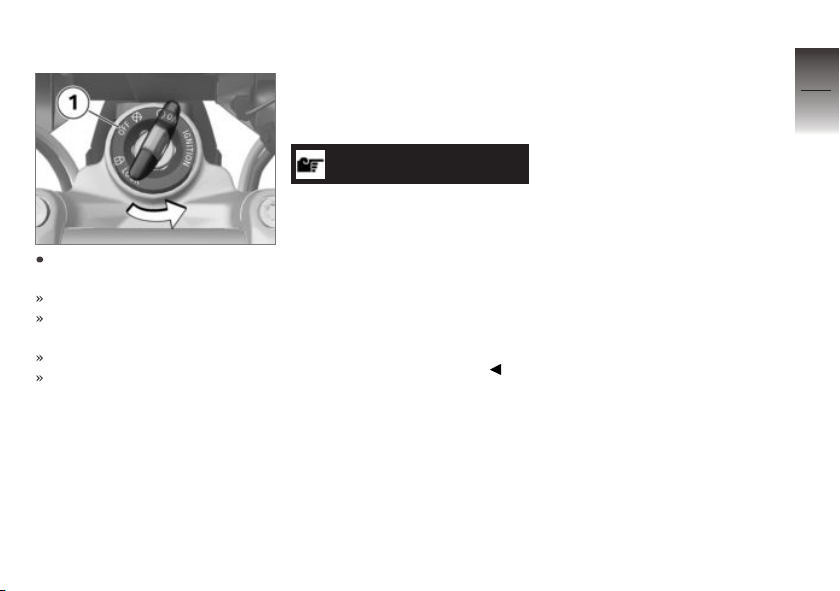
Switching off ignition
Turn the ignition key to position 1.
Lights are switched off.
Handlebars (steering lock) are
not locked.
Key can be removed.
The number-plate light goes
out after 10 seconds.
Electronic immobiliser EWS
The electronic design of the
motorcycle allows it to access
data stored in the ignition key
by means of a ring antenna loc-
ated in the ignition switch/steering lock. The engine control unit
will only allow the engine to be
started if the key is identified as
“authorised”.
NOTICE
A spare key attached to the
same ring as the ignition key
used to start the engine could
"irritate" the electronics, in
which case the enabling signal
for starting is not issued. The
EWS warning appears in the
multifunction display.
Always keep the spare key separately from the ignition key.
If you lose a key, you can have
it barred by your authorised
BMW Motorrad dealer.
If you wish to do this, you will
need to bring all other keys for
the motorcycle with you. The
engine cannot be started by a
barred key, but a key that has
been barred can subsequently be
reactivated.
You can obtain extra keys
only through an authorised
BMW Motorrad dealer. The
keys are part of an integrated
security system, so the dealer is
under an obligation to check the
legitimacy of all applications for
replacement/extra keys.
4
41
z
Operation
Page 44
Multifunction display
4
Selecting the display
42
mode
z
Operation
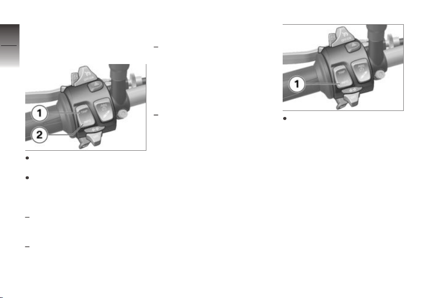
Press button 1 to view the
ROAD display mode.
Press button 2 to view other
display modes.
The display modes at your disposal are as follows:
ROAD: All the information ne-
cessary for riding on public
roads is presented here.
LAPTIMER: Lap times and
other data can be logged here
and subsequently retrieved
in the RACE INFO display
mode.
RACE INFO: The information
logged with the LAPTIMER
can be retrieved for viewing
here. Note that this display
mode can be activated only
when the motorcycle is at a
standstill.
SETUP MENU: The instrument panel can be configured
to suit the rider's preferences
here. Note that this display
mode can be activated only
when the motorcycle is at a
standstill.
When the display
shows RACE INFO or
SETUP MENU, as applicable,
press and hold down button 1
to activate the mode.
Page 45
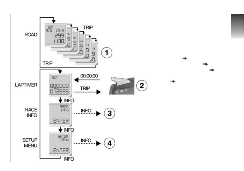
Overview of the display
modes
— Solid line: short-press the
button.
‑ ‑ Broken line: press and
hold down the button.
1 On-board computer read-
ings ( 44)
2 Starting timing ( 68)
3 Start RACE INFO ( 70)
4 Start SETUP MENU
( 75)
4
43
z
Operation
Page 46
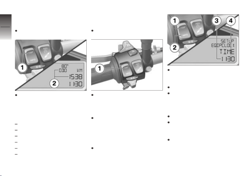
Selecting readings in
4
ROAD mode
Switch on the ignition.
44
z
Operation
Repeatedly press button 1 until
the value you want appears in
panel 2.
The following values can be displayed:
Total distance covered
Range
Tripmeter 1 Trip I
Tripmeter 2 Trip II
Average consumption
Average speed
Resetting the average
values
Switch on the ignition.
Repeatedly short-press button 1 until the average value
you want to reset appears in
the display line.
Press and hold down button 1
until the value you selected has
reset.
Setting the clock
Switch on the ignition.
Repeatedly press button 2 until
SETUP MENU ENTER ap-
pears on the display.
Press and hold down button 2.
Repeatedly press button 2
until SETUP EQUIPMENT
ENTER appears on the
display.
Press and hold down button 2.
Repeatedly press button 2 until
SETUP EQUIP:CLOCK
TIME appears on the display.
Press and hold down button 2
until the minutes number 4
flashes.
Page 47

Press button 1 to step the
minutes reading up.
Press button 2 to step the
minutes reading down.
When the minutes reading is
correct, hold down button 2
until hours reading 3 flashes.
Press button 1 to step the
hours reading up.
Press button 2 to step the
hours reading down.
When the hours reading is correct, press and hold down button 2 until the number stops
flashing.
This completes the process.
4
45
z
Operation
Page 48

Anti-theft alarm (DWA)
4
with alarm system (DWA)
46
Activation
Switching on ignition ( 40).
DWA adjusting ( 47).
Switch off the ignition.
If the alarm system (DWA) is
activated, then the alarm sys-
tem (DWA) will be armed auto-
matically when the ignition is
switched off.
z
Operation
Activation takes approximately
30 seconds to complete.
Turn indicators flash twice.
Confirmation tone sounds
twice (if programmed).
Anti-theft alarm (DWA) is act-
ive.
Alarm
An alarm can be triggered by:
OE
motion sensor
an attempt to use an unauthorised key to switch on the
ignition
disconnection of the DWA antitheft alarm from the motorcycle's battery (DWA internal
battery in the anti-theft alarm
provides power - alarm tone
only, the turn indicators do not
flash).
All functions are sustained even
if the internal battery of the DWA
anti-theft alarm system is flat; the
only difference is that an alarm
cannot be triggered if the system
is disconnected from the motorcycle's battery.
An alarm lasts for approximately
26 seconds. While an alarm is in
progress an alarm tone sounds
and the turn indicators flash. The
type of alarm tone can be set by
an authorised BMW motorcycle
dealer.
If an alarm was triggered while
the motorcycle was unattended,
the rider is notified accordingly
by an alarm tone sounding once
when the ignition is switched on.
The DWA LED then indicates
the reason for the alarm for one
minute.
The meanings of the flash codes
are as follows:
Flashes 1x: Motion sensor 1
Flashes 2x: Motion sensor 2
Flashes 3x: Ignition switched
on with unauthorised key
Flashes 4x: Disconnection of
the DWA anti-theft alarm from
the motorcycle's battery
Flashes 5x: Motion sensor 3
Deactivation
Kill switch in operating position
(run).
Switch on the ignition.
Page 49

Turn indicators flash once.
Confirmation tone sounds once
(if programmed).
Anti-theft alarm (DWA) is deactivated.
DWA adjusting
Switching on ignition ( 40).
4
47
Repeatedly shortpress button 1 until
SETUP MENU ENTER
appears in display line 2.
Long-press button 1 to start
the SETUP MENU.
Repeatedly short-press button 1 until SETUP EQUIP-
MENT ENTER appears in
display line 2.
Long-press button 1 to start
the SETUP EQUIPMENT
menu.
Press button 1 briefly to
go to the next menu item
SETUP EQIP DWA.
AUTO appears in display
line 2.
The preset ON/OFF value
appears in display line 3.
Long-press button 1 to change
the preset value.
The following settings are available:
AUTO ON: The DWA anti-
theft alarm is active and will be
armed automatically when the
ignition is switched off.
z
Operation
Page 50
AUTO OFF: The DWA anti-
theft alarm is deactivated.
4
48
Headlight
Adjusting headlight for
driving on left/driving on
right
This motorcycle has a
symmetric-beam low-beam
headlight. If the motorcycle
is ridden in a country where
z
Operation
the opposite rule of the road
applies, its symmetric lowbeam headlight means that
no measures are necessary to
prevent the headlight beam from
dazzling oncoming traffic.
Headlight beam throw and
spring preload
Headlight beam throw is generally kept constant when spring
preload is adjusted to suit load.
NOTICE
If there are doubts about the correct headlight beam throw, have
the setting checked by a specialist workshop, preferably an authorised BMW Motorrad dealer.
Lights
Side light
The side lights switch on automatically when the ignition is
switched on.
NOTICE
The side lights place a strain on
the battery. Do not switch the
ignition on for longer than absolutely necessary.
Low-beam headlight
The low-beam headlight switches
on automatically when you start
the engine.
High-beam headlight and
headlight flasher
Start the engine.
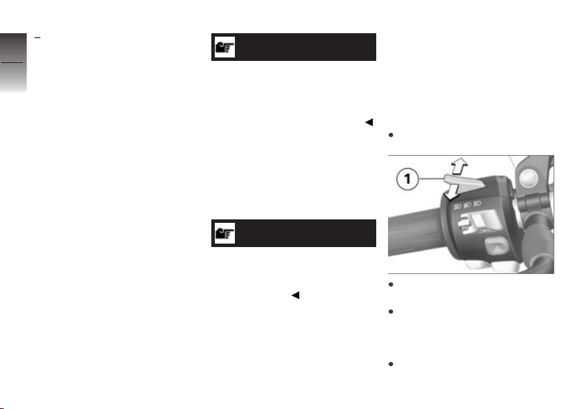
Push switch 1 up to switch on
the high-beam headlight.
Press switch 1 down to operate the headlight flasher.
Parking lights
Switch off the ignition.
Page 51
Immediately after switching off
the ignition, push button 1 to
the left and hold it in this position until the parking lights
come on.
NOTICE
You can switch on the parking
lights within 10 seconds after
switching off the ignition.
Switch the ignition on and off
again to switch off the parking
lights.
Turn indicators
Operating the turn
indicators
Switch on the ignition.
NOTICE
The turn indicators are cancelled
automatically after the defined
time and distance. The defined
time and distance can be set by
an authorised BMW Motorrad
dealer.
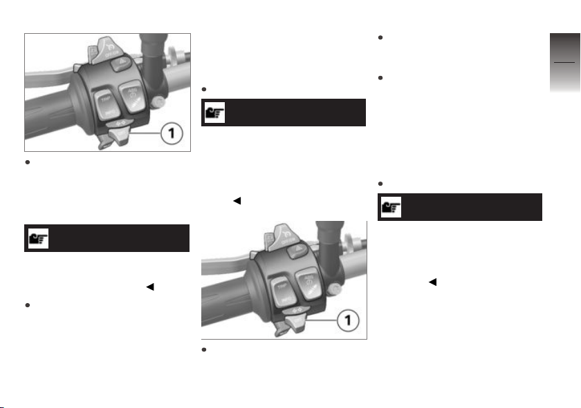
Push button 1 to the left to
switch on the left turn indicators.
Push button 1 to the right to
switch on the right turn indicat-
ors.
Operate centre button 1 to
cancel the turn indicators.
Hazard warning flashers
Switching on hazard
warning flashers
Switch on the ignition.
NOTICE
The hazard warning flashers
place a strain on the battery.
Do not use the hazard warning
flashers for longer than absolutely
necessary.
4
49
z
Operation
Page 52
4
50
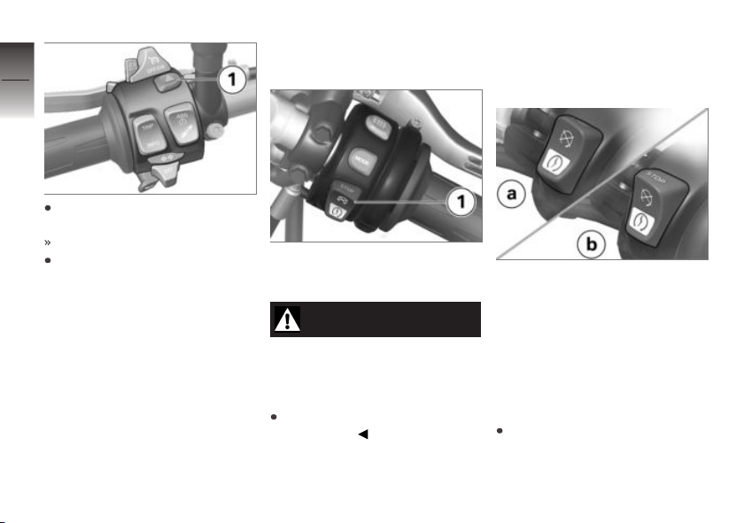
Press button 1 to switch on
the hazard warning flashers.
Ignition can be switched off.
z
Operation
To switch off the hazard warning flashers, switch on the ignition and press button 1 again.
Emergency off switch (kill switch)
1 Emergency off switch (kill
switch)
WARNING
Operation of the kill switch
while riding.
Risk of fall due to rear wheel
locking.
Do not operate the kill switch
when riding.
The emergency off switch is a
kill switch for switching off the
engine quickly and easily.
a Engine switched off
b Normal operating position
(run)
BMW Motorrad Race
ABS
Switch off the ABS
function
Switch on the ignition.
Page 53
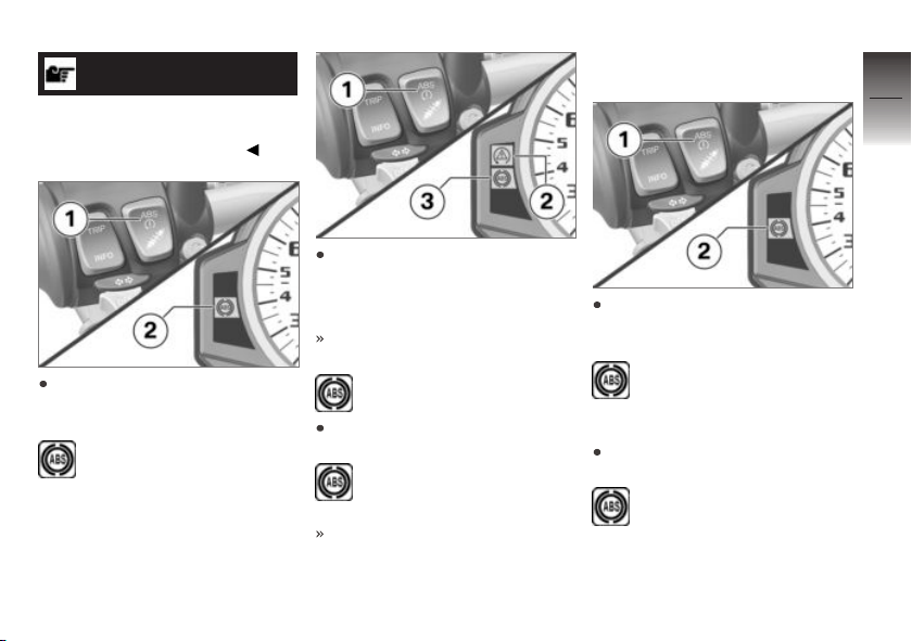
NOTICE
You have the option of deactivating the ABS function while the
motorcycle is on the move.
Press and hold down button 1
until ABS telltale and warning
light 2 changes status.
ABS telltale and warning
light shows.
Press and hold down button 1
until first DTC warning light 2
and then ABS telltale and
warning light 3 change status.
The DTC setting remains unchanged.
ABS telltale and warning
light shows.
Release button 1 within two
seconds.
ABS telltale and warning
light remains on.
ABS function is switched off.
Switch on the ABS
function
Press and hold down button 1
until ABS telltale and warning
light 2 changes status.
ABS telltale and warning
light goes out; if selfdiagnosis has not completed it
starts flashing.
Release button 1 within two
seconds.
ABS telltale and warning
light remains off or continues to flash.
4
51
z
Operation
Page 54
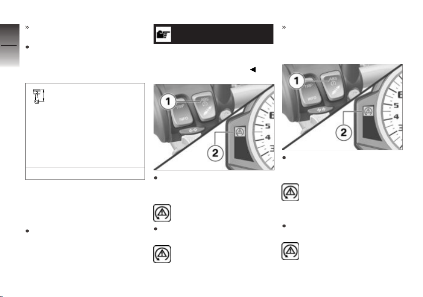
ABS telltale and warning light
switched on.
4
If the coding plug is not inser-
52
ted, you have the alternative of
switching the ignition off and
then on again.
An ABS fault has oc-
curred if the ABS telltale
and warning light shows when
the motorcycle accelerates to
a speed in excess of the minimum stated below after the
z
Operation
ignition was switched off and
then on again.
min 5 km/h
BMW Motorrad ASC
Switch off the ASC
function
Start the engine.
NOTICE
You have the option of deactivating the ASC function while the
motorcycle is on the move.
Press and hold down button 1
until ASC telltale and warning
light 2 changes status.
ASC telltale and warning
light starts to show.
Release button 1 within two
seconds.
ASC telltale and warning
light remains on.
ASC function is switched off.
Switch on the ASC
function
Press and hold down button 1
until ASC telltale and warning
light 2 changes status.
ASC telltale and warn-
ing light goes out; if selfdiagnosis has not completed it
starts flashing.
Release button 1 within two
seconds.
ASC telltale and warning
light remains off or continues to flash.
Page 55
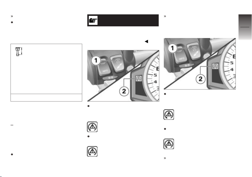
ASC function is switched on.
If the coding plug is not inserted, you have the alternative of
switching the ignition off and
then on again.
An ASC fault has oc-
curred if the ASC telltale
and warning light shows when
the motorcycle accelerates to
a speed in excess of the minimum stated below after the
ignition was switched off and
then on again.
min 5 km/h
Dynamic Traction Control DTC
with Dynamic Traction Control
OE
(DTC)
Switch off the DTC
function
Start the engine.
NOTICE
You have the option of deactivating the DTC function while the
motorcycle is on the move.
Press and hold down button 1
until DTC warning light 2
changes status.
DTC warning light starts to
show.
Release button 1 within two
seconds.
DTC warning light continues to flash.
DTC function is switched off.
Switch on the DTC
function
Press and hold down button 1
until DTC warning light 2
changes status.
DTC warning light goes
out; if self-diagnosis has not
completed it starts flashing.
Release button 1 within two
seconds.
DTC warning light remains
off or continues to flash.
DTC function is switched on.
4
53
z
Operation
Page 56
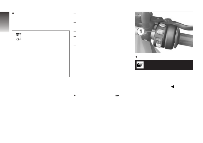
If the coding plug is not inserted, you have the alternative of
4
switching the ignition off and
54
then on again.
A DTC fault has
occurred if the DTC
warning light shows when
the motorcycle accelerates
to a speed in excess of the
minimum stated below after
the ignition was switched off
and then on again.
z
Operation
min 5 km/h
Riding mode
Using the riding modes
BMW Motorrad has developed
4 operational scenarios for your
motorcycle from which you can
select the scenario suitable for
your situation:
Riding on a rain-wet road surface.
Riding on a dry road surface.
with Pro riding modes
Dynamic riding on a dry road
surface.
Sporty riding on a dry road surface.
The interplay of engine torque,
throttle response, ABS control
and ASC or DTC control is optimised for each of these 4 scenarios. The optimum setting is a
preset with DDC.
OE
Setting riding mode
Switching on ignition ( 40).
Press button 1.
NOTICE
See the section entitled "Engineering details" for more information on the various ride modes
that can be selected.
Page 57
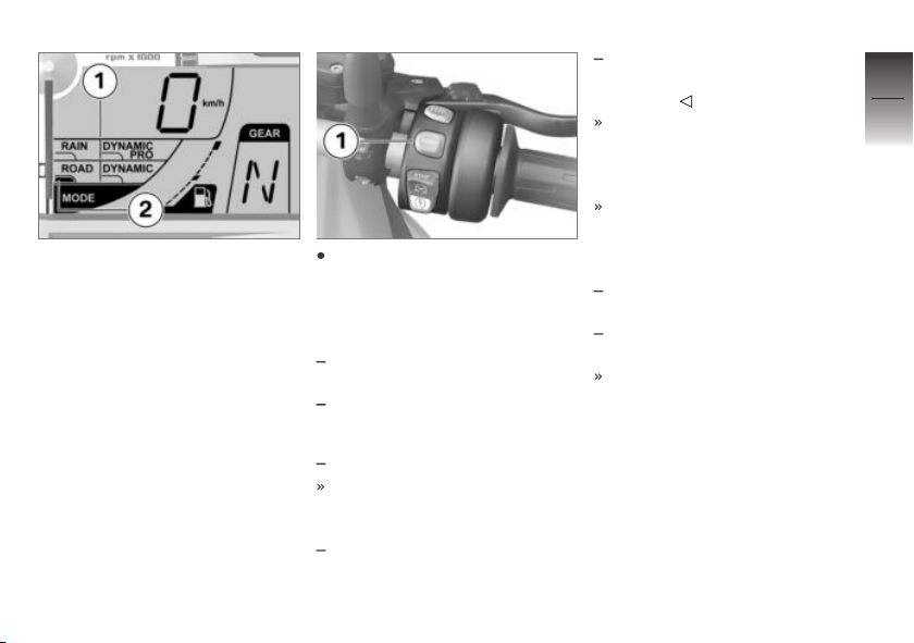
Selection menu 1 with the four
selectable riding modes appears
on the display. The highlight 2
tells you which riding mode is
currently selected.
Repeatedly press button 1 until
the riding mode you want is
highlighted.
The following ride modes can be
selected:
RAIN: For riding on a rain-wet
road surface.
ROAD: For riding on a dry road
surface.
with Pro riding modes
The following riding modes are
additionally available for selec-
tion:
OE
DYNAMIC: For dynamic riding
on a dry road surface.
DYNAMIC PRO: For sporty
riding (only with coding plug
installed).
With the motorcycle at a standstill, the selected mode is activated after approximately two
seconds.
The newly selected riding
mode is activated as you
ride only when the following
preconditions are satisfied:
The throttle twistgrip is in the
idle position.
The brake levers are in the released positions.
The mode selected in this way
is retained with the enginecharacteristic, ABS, DTC and
DDC adaptation settings even
after the ignition has been
switched off.
4
55
z
Operation
Page 58
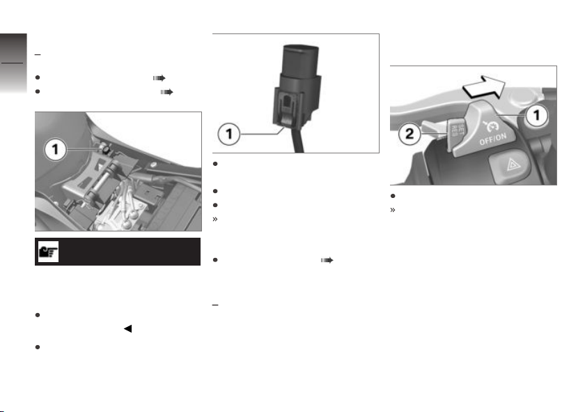
Installing coding plug
4
with Pro riding modes
56
Switching off ignition ( 41).
Remove the front seat ( 62).
z
Operation
ATTENTION
Dirt and damp penetrating
inside open connectors.
Malfunctions
Reinstall the cap after removing
the coding plug.
Remove cap of plug 1.
OE
To do so, press in latch 1 and
remove the cap.
Install the coding plug.
Switch on the ignition.
The selected riding mode is
retained in memory, even after
the ignition is switched off.
Installing front seat ( 62).
Cruise-control system
with cruise control
OE
Switching on cruise
control
Slide switch 1 to the right.
Button 2 is enabled for operation.
Page 59
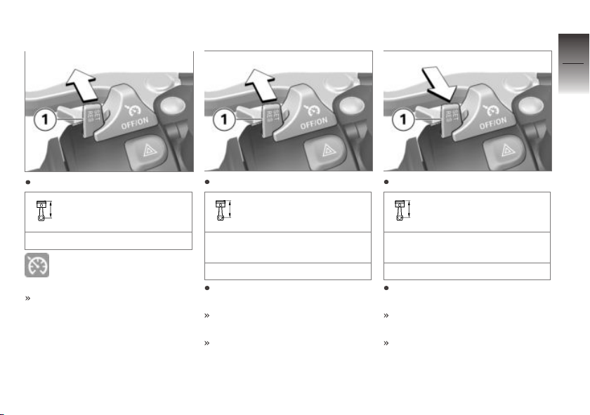
Saving road speed
Accelerating
Decelerating
4
57
Briefly push button 1 forward.
Adjustment range for
cruise control
30...180 km/h
Telltale light for cruise con-
trol shows.
The motorcycle maintains your
current cruising speed and the
setting is saved.
Briefly push button 1 forward.
Increasing speed
Speed is increased each time
you press the button.
1 km/h
Push button 1 forward and
hold it in this position.
The motorcycle accelerates
steplessly.
The current speed is maintained and saved if button 1 is
not pushed again.
Briefly push button 1 back.
Reducing speed
Speed is reduced each time
you push the button.
1 km/h
Push button 1 back and hold it
in this position.
The motorcycle decelerates
steplessly.
The current speed is maintained and saved if button 1 is
not pushed again.
z
Operation
Page 60
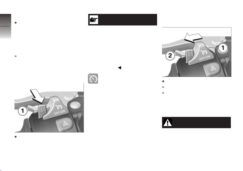
Deactivate cruise control
4
Brake, pull the clutch lever
or turn the throttle twistgrip
58
(close the throttle by turning
the twistgrip back past the
idle position) to deactivate the
cruise-control system.
Telltale light for cruise control
goes out.
Resuming former cruising
speed
z
Operation
Briefly push button 1 back to
return to the speed saved beforehand.
NOTICE
Opening the throttle does not
deactivate the cruise-control system. If you release the twistgrip
the motorcycle will decelerate
only to the cruising speed saved
in memory, even though you
might have intended slowing to
a lower speed.
Telltale light for cruise control shows.
Switching off cruise
control
Slide switch 1 to the left.
The system is deactivated.
Button 2 is disabled.
Brakes
Adjusting brake lever
WARNING
Changed position of the
brake fluid reservoir.
Air in the brake system.
Page 61
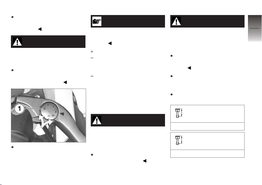
Do not turn the handlebars or
the handlebar fitting on the
handlebar.
WARNING
Adjusting the brake lever
while riding.
Risk of accident
Do not attempt to adjust the
brake lever unless the motorcycle is at a standstill.
Turn knob 1 to the desired position.
NOTICE
The adjuster is easier to turn
if you push the brake lever
forward.
Adjustment options:
Position 1: largest span
between handlebar grip and
brake lever
Position 6: smallest span
between handlebar grip and
brake lever
Tyres
Checking tyre pressure
WARNING
Incorrect tyre pressure.
Impairment of the motorcycle's
handling characteristics. Shorter
useful tyre life.
Always check that the tyre
pressures are correct.
WARNING
Tendency of valve inserts to
open by themselves at high
riding speeds.
Sudden loss of tyre pressure.
Install valve caps fitted with
rubber sealing rings and tighten
firmly.
Make sure the ground is level
and firm and place the motorcycle on its stand.
Check tyre pressures against
the data below.
Tyre pressure, front
2.5 bar (Tyre cold)
Tyre pressure, rear
2.9 bar (Tyre cold)
4
59
z
Operation
Page 62
If tyre pressure is too low:
4
Correct tyre pressure.
60
Heated handlebar grips
with heated handlebar grips
Operating the heated
handlebar grips
Start the engine.
NOTICE
z
Operation
The heating in the heated
handlebar grips can be activated
only when the engine is
running.
NOTICE
The increase in power consumption caused by having the heated
handlebar grips switched on can
drain the battery if you are riding at low engine speeds. If the
charge level is low, the heated
handlebar grips are switched off
to ensure the battery's starting
capability.
OE
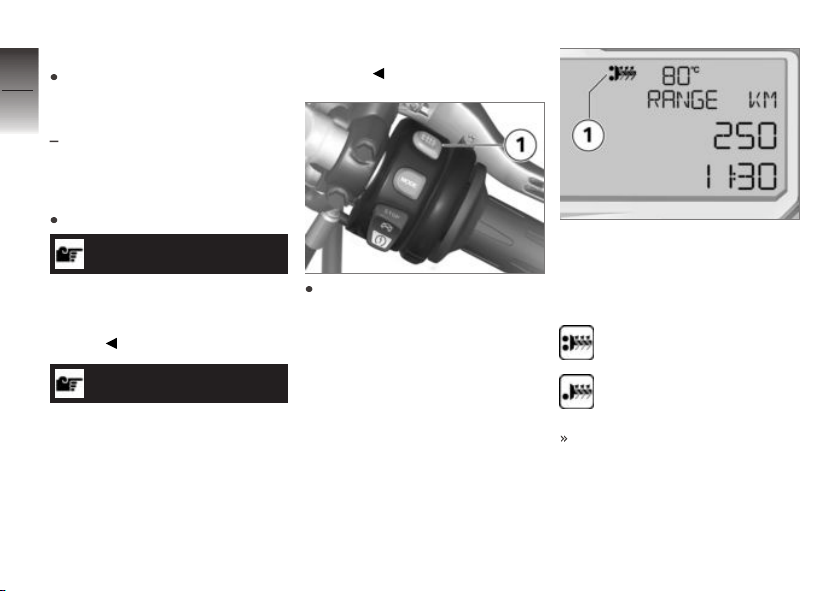
Repeatedly press button 1 until
the heating stage you want to
use appears on the multifunction display.
The handlebar grips have twostage heating. Stage two 1 is
for heating the grips quickly: it is
advisable to switch to stage one
as soon as the grips are warm.
Second stage: 100 %
heating power
First stage: 50 % heating
power
The selected heating stage will
be saved if you allow a certain
length of time to pass without
making further changes.
Page 63
Mirrors
Adjusting mirrors
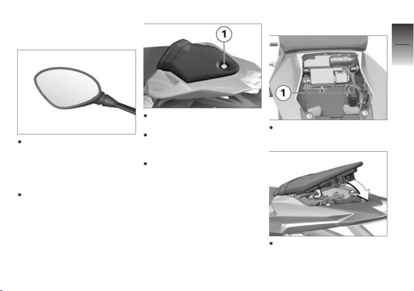
Turn the mirror to the desired
position.
Front and rear seats
Removing rear seat
Make sure the ground is level
and firm and place the motorcycle on its stand.
Open seat lock 1 with the ignition key.
Lift the rear seat at the rear
and then work it back and up
to remove.
Remove the ignition key from
the lock and place the rear
seat, upholstered side down,
on a clean surface.
Install the rear seat
Engage the rear seat in
mounts 1 on left and right.
Swing the rear seat down,
pushing it lightly forward.
4
61
z
Operation
Page 64
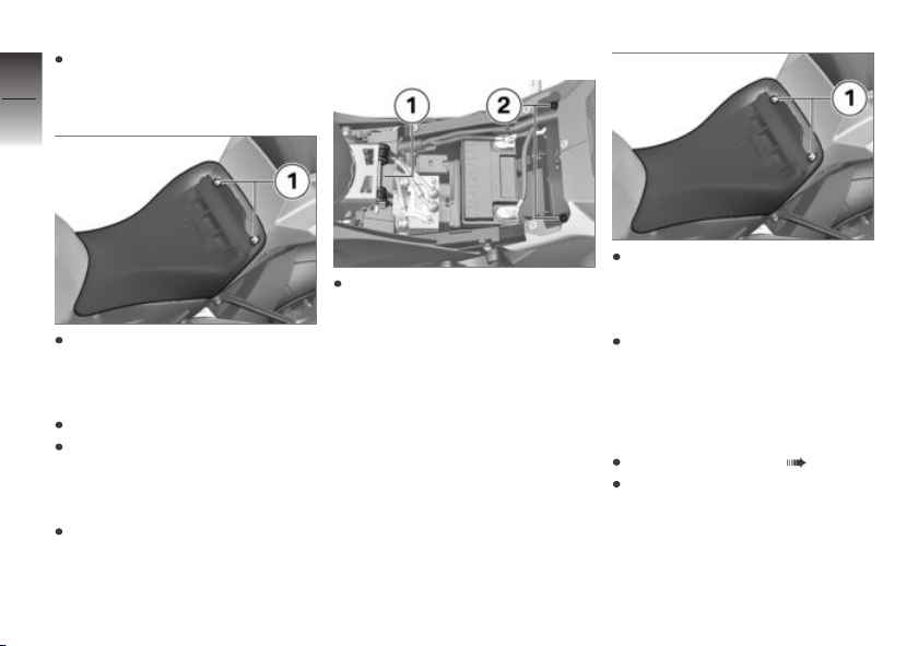
Lock the seat lock with the ignition key.
4
62
Removing front seat
z
Operation
Push the upholstery of the
front seat forward slightly
above screws 1 and hold it in
this position.
Remove screws 1.
Push the seat forward and
lift it at the rear to remove.
Take care not to let the screws
scratch the trim panels.
Place the seat, upholstered
side down, on a clean surface.
Installing front seat
Engage the front seat in
mount 1, then lower the rear of
the seat to bring the holes into
alignment with screw holes 2.
Take care not to let the screws
scratch the trim panels.
Push the upholstery of the
front seat forward slightly
above the screw holes and
hold it in this position.
Install screws 1.
Helmet holder
Securing the helmet to
motorcycle
Removing rear seat ( 61).
Turn the rear seat upside
down.
Page 65
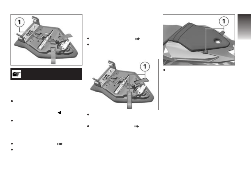
Luggage loops
Securing luggage to
motorcycle
Removing rear seat ( 61).
Turn the rear seat upside
down.
4
63
ATTENTION
Incorrect positioning of the
helmet lock.
Scratch marks on trim panel.
Make sure the lock is out of
the way when you hook the
helmet into position.
Use a plastic-sheathed steel
cable (not part of the vehicle)
to secure the helmet to helmet
holder 1.
Install the rear seat ( 61).
Place the helmet on the front
seat.
Pull loops 1 out of the holders
and to the outside and down.
Install the rear seat ( 61).
Use the loops 1 and the rear
footrests, for example, to secure luggage to the rear seat.
In this process, take care not to
damage the rear trim panels.
z
Operation
Page 66

4
64
z
Operation
Page 67

On the race track
LAPTIMER . . . . . . . . . . . . . . . . . . . . . . . . . 66
RACE INFO. . . . . . . . . . . . . . . . . . . . . . . . . 70
SETUP MENU . . . . . . . . . . . . . . . . . . . . . . 75
Spring preload . . . . . . . . . . . . . . . . . . . . . . 78
Damping . . . . . . . . . . . . . . . . . . . . . . . . . . . . 81
Removing/installing mirrors . . . . . . . . . 85
Removing and installing number-
plate carrier . . . . . . . . . . . . . . . . . . . . . . . . . 86
Removing and installing front turn
indicators . . . . . . . . . . . . . . . . . . . . . . . . . . . 89
5
65
z
On the race track
Page 68
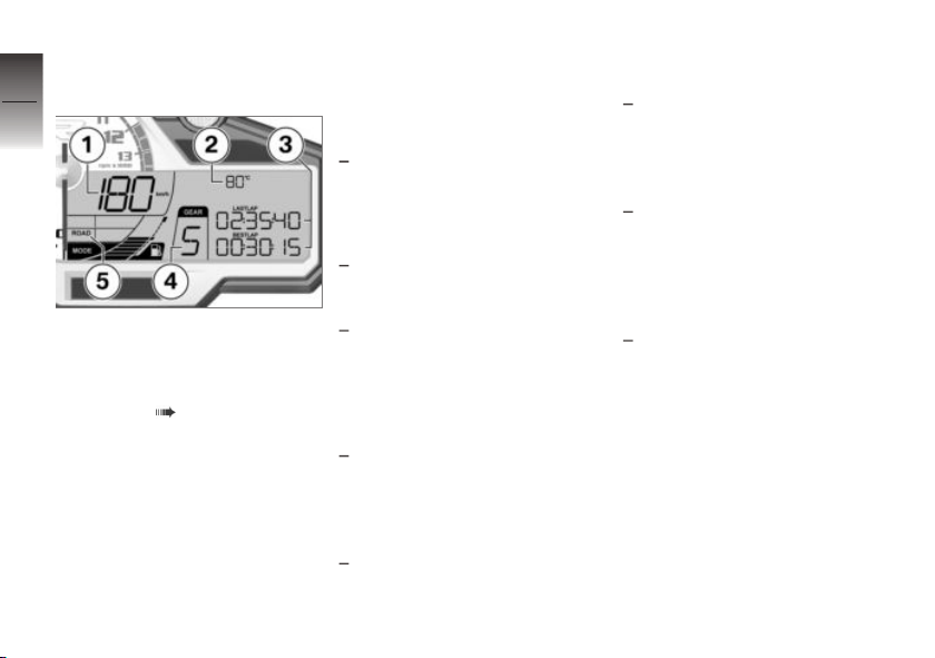
LAPTIMER
5
Mode of presentation
66
1 Speedometer
2 Engine temperature
3 The readings in these lines
z
On the race track
can be changed by the
rider. ( 66)
LASTLAP: Time for the
preceding lap.
BESTLAP: The fastest of
the laps currently logged in
memory.
4 Gear indicator
5 Riding mode selected by
the rider
Labels for the values
shown on the display
The following times can be
displayed in the third line:
LASTLAP: The time for the
preceding lap.
The following times can be
displayed in the fourth line:
BESTLAP: The fastest of
the laps currently logged in
memory.
RUN: The running time for the
current lap.
The third and fourth lines can
be combined to show other
readings:
RUN BEST: The third line
shows the running time for
the current lap, the best lap
currently logged in memory is
shown in the fourth line.
LAST RUN: The third line
shows the time recorded for
the preceding lap, the running
time for the current lap is
shown in the fourth line.
LAST BEST: The third line
shows the time needed for
the preceding lap, the best lap
currently logged in memory is
shown in the fourth line.
RUN TOTAL: The third line
shows the running time for the
current lap, the total time for
all the laps currently logged in
memory is shown in the fourth
line.
RUN BEStEV: The third line
shows the running time for the
current lap, the best-ever lap is
shown in the fourth line.
At the start of each new lap the
time for the preceding lap is
shown briefly before the display
switches to the running time of
the current lap.
Page 69
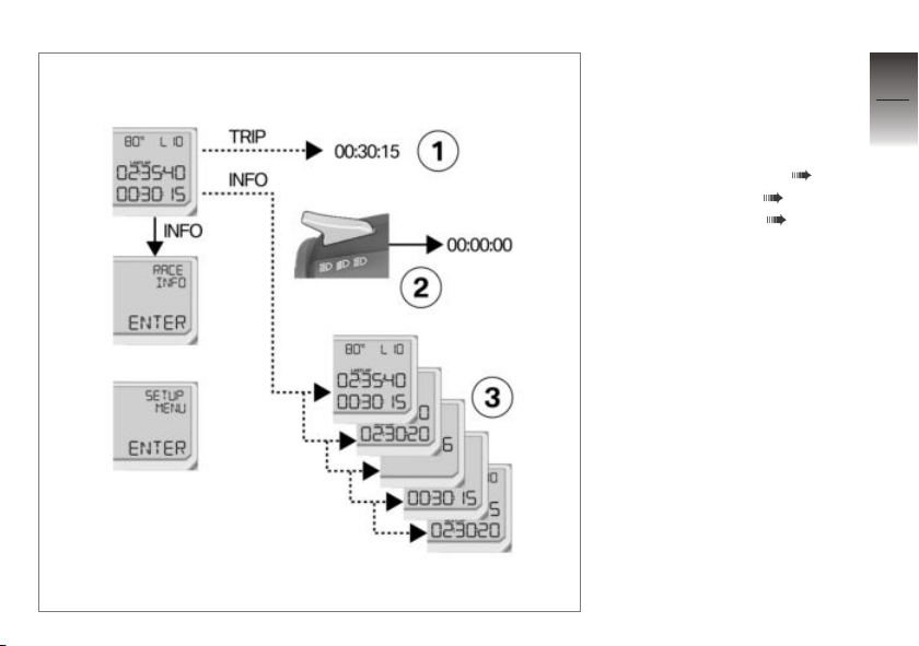
Display overview
— Solid line: short-press the
button.
‑ ‑ Broken line: press and
hold down the button.
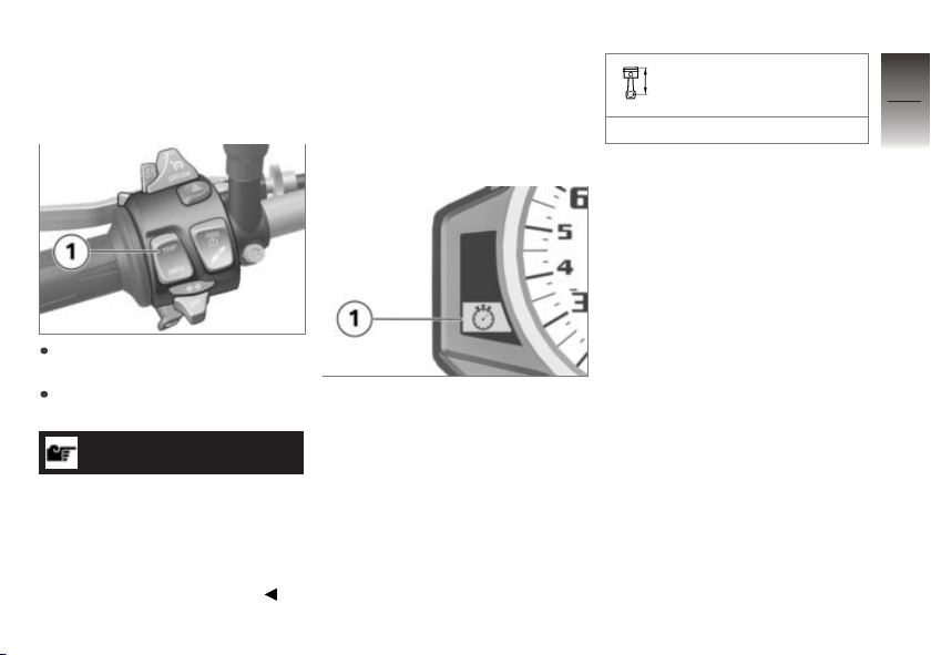
1 Interrupting timing ( 69).
2 Starting timing ( 68).
3 View the times ( 68).
5
67
z
On the race track
Page 70
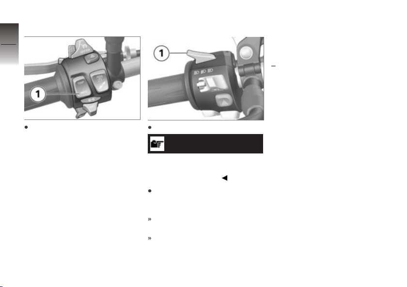
Viewing times
5
68
To view the time of your
choice, repeatedly press
button 1 until the display
changes.
z
On the race track
Starting timing
Press switch 1 to start timing.
NOTICE
The engine has to be running
in order for the headlight-flasher
signal to be detected.
Every time you cross the start/
finish line, press switch 1 again
to start timing for the next lap.
The data of the preceding lap
are written into memory.
Timing continues even if you
exit the display mode. In the
other display modes, however,
timing of another lap can be
started only by an external signal.
Infrared receiver
with infrared receiver
An infrared signal provides a convenient way of operating the lap
timer. The instrument can be operated in this way only when the
infrared receiver available as an
optional accessory is connected
to the IR receiver (on the right
side, behind the side panel). The
OA
RACETRACK SETUP MENU
enables you to choose between
operation with the headlightflasher button and the TRIP/INFO
button, or operation by one or
other of these buttons (see the
section on the SETUP MENU).
A lap timeout can be defined to
stop the receiver from registering
completion of a lap prematurely
in response to spurious signals.
Page 71
Signals received before this time
elapses are ignored.
Interrupting timing
Press and hold down button 1
to interrupt timing.
Press and hold down button 1
again to resume timing.
NOTICE
If more laps are subsequently
timed, lap numbering resumes.
Numbering is not restarted at
lap 1 unless you delete the
current timing session in the
RACE INFO display mode.
Fastest lap anticipated
This function has to be activated
in the SETUP RACETRACK
menu (see the section on the
SETUP MENU).
When you start a new lap your
intermediate times are taken
every time you cover a defined
section of the track and compared with the corresponding
intermediate times of the best lap
stored in memory.
The lap section for the
intermediate time
100 m
If your intermediate times show
that you are faster than on your
previous best lap the processor
anticipates that this lap will be
your new best time. The indicator for the fastest lap 1 lights
up.
5
69
z
On the race track
Page 72
RACE INFO
5
Selecting saved lap
70
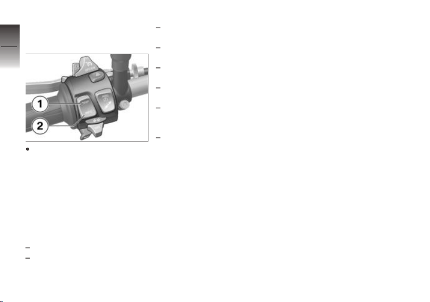
Repeatedly press button 1
or button 2 to view each lap
stored in memory one after the
other.
z
On the race track
Repeatedly press button 1 to
step through the laps stored
in memory in the following sequence. Repeatedly press button 2 to step through them in
the opposite sequence:
Best-ever lap BEST-EVER
Best lap logged in memory
BEST
Last lap logged in memory
LAST
All other laps logged in
memory
Aggregate time for all laps
logged in memory TOTAL
Delete lap data logged in
memory DELETE LAPS.
Delete the best-ever lap
logged in memory BEST-
EVER DELETE.
Exit the RACE INFO EXIT
display mode.
Page 73
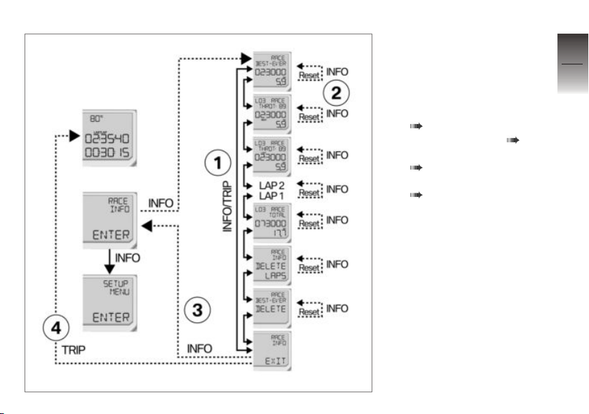
Display overview
— Solid line: short-press the
button.
‑ ‑ Broken line: press and
hold down the button.
1 Selecting saved lap
( 70).
2 Deleting lap times ( 73).
3 Exit the INFO MENU
( 72).
4 Delete the timing logs
( 73).
5
71
z
On the race track
Page 74
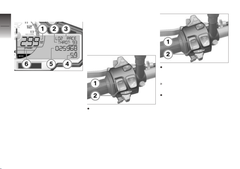
Information for a lap
5
72
1 In sequence: Top speed
(max), average speed (Ø)
and lowest speed (min) on
the lap currently displayed.
2 In sequence: Average
z
On the race track
throttle twistgrip position
(THROT) in percent, percentage of lap ridden with
brakes applied (BRAKE)
and number of gearshifts
(GEAR) on the lap currently
displayed.
3 Lap for which the data on
the display apply.
4 Distance ridden.
5 Time for the lap currently
displayed.
6 The riding mode most
commonly used is displayed continuously.
Exiting INFO MENU
Press and hold down button 2
to exit the RACE INFO display
mode.
The readings already recorded
remain saved in memory.
Alternatively: Press and hold
down button 1.
Repeatedly press button 1 or button 2 until
RACE INFO EXIT appears
on the display.
Page 75
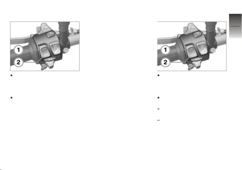
Deleting timing logs
Repeatedly press button 1 or
button 2 until RACE INFO DELETE LAPS appears on the
display.
Press and hold down button 2
to delete all the logged data
from memory.
All-time best lap
The all-time best lap (BEST-
EVER) is the fastest of all timed
laps and is updated as soon as a
faster lap BESTLAP is timed.
The all-time best lap remains
stored in memory even if the
timed laps are deleted. This
means that other races can subsequently be timed and the lap
times of those races compared
with the best lap from earlier
races.
The all-time best lap can also be
deleted from memory.
If the all-time best lap is from a
race timed in the past, it is accompanied on the display by the
appropriate lap number. If the alltime best lap shows without a lap
number, this lack of a lap number
indicates that the time is from a
race timed in the past but subsequently deleted from memory.
Deleting lap times
Repeatedly press button 1
or button 2 until the lap you
want to delete appears on the
display.
Press and hold down button 2
to delete the lap from memory.
If the lap you select for deletion
was
the best lap in memory BEST,
the lap in question is deleted.
The lap that was the secondbest time until the best time
was deleted becomes the new
best lap.
5
73
z
On the race track
Page 76

the last lap in memory LAST,
the lap in question is deleted.
5
The lap that was the second-
74
last time until the last time was
deleted becomes the new last
lap.
a lap stored in memory, the
lap in question is deleted. The
numbering of the remaining
laps remains unchanged.
Total time is reduced by the
time for the laps you delete.
Select BEST-EVER DE-
LETE and press and hold
down button 2 to delete the
BEST-EVER lap time.
z
On the race track
Page 77
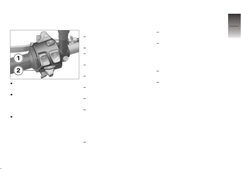
SETUP MENU
Selecting a parameter
Select the SETUP MENU and
press and hold down button 2.
Repeatedly press button 1 or
button 2 until the submenu
you want appears on the
display.
Press and hold down button 2
to open the submenu you
want.
Each time button 1 is pressed
the possible parameters
are shown in the sequence
described below; each time
button 2 is pressed the
parameters are shown in reverse
sequence.
SETUP EQUIPMENT
Adjust the alarm system setting
(DWA) DWA AUTO ON/OFF.
Set the time CLOCK TIME.
Adjust display brightness
DISP BRIGHT.
Switch warning for defective
bulbs on/off WARN LAMP.
Switch gearshift light on/off
GSL ON/OFF RPM.
Gearshift-light brightness
GSL BRIGHT
Gearshift-light frequency
GSL FREQ
Change units of measure for
speed, range, temperature, average consumption, distance
and time UNITS
SETUP RACETRACK
Set LAPTIMER readings: Current lap RUN, time required for
preceding lap LAST, best lap
BEST, total of all laps logged
in memory TOTAL, best-ever
lap BEStEV
Display-freeze period for the
most recent time HOLD
Debounce time (time that must
elapse before a new lap can
be started) of the TRIP/INFO
button for operating the LAP-
TIME DEB-TM
Activate or deactivate
BESTLAP BLIP ON/OFF.
Change settings for operating
the LAPTIME by the
headlight-flasher button
and the TRIP/INFO button.
TRIG AUTO: operate by
headlight-flasher button
and TRIP/INFO button;
TRITG MANUAL: operate by
headlight-flasher button only;
EXTERN: operate by TRIP/
INFO button only.
5
75
z
On the race track
Page 78
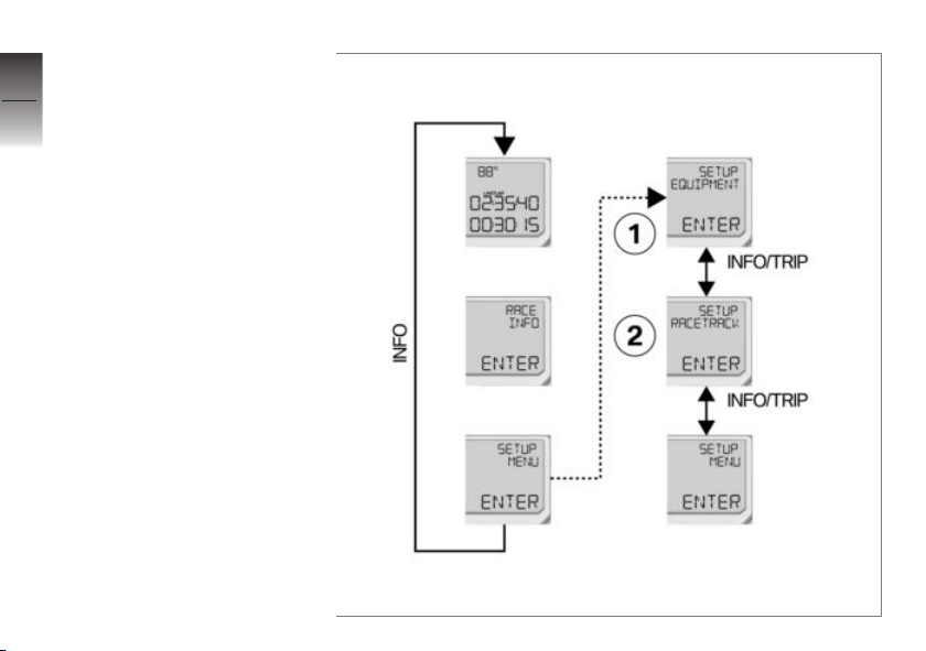
Overview SETUP MENU
5
— Solid line: short-press the
76
z
On the race track
button.
‑ ‑ Broken line: press and
hold down the button.
1 Settings of the display
2 Settings for the racetrack
Page 79
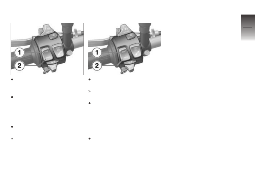
Setting parameters
Exiting SETUP mode
5
77
Press and hold down button 2
until the parameter starts to
flash.
Repeatedly press button 1 or
button 2 until the value you
want appears on the display.
When the value you want is
shown:
Press and hold down button 2
until the value stops flashing.
The value is saved.
To exit the SETUP MENU,
press and hold down button 1.
A value that is still flashing will
not be saved.
Alternatively: Repeatedly
press button 1 or button 2 until
SETUP MENU EXIT ap-
pears on the display.
When SETUP MENU EXIT appears:
Press and hold down button 2
to exit the SETUP MENU.
z
On the race track
Page 80
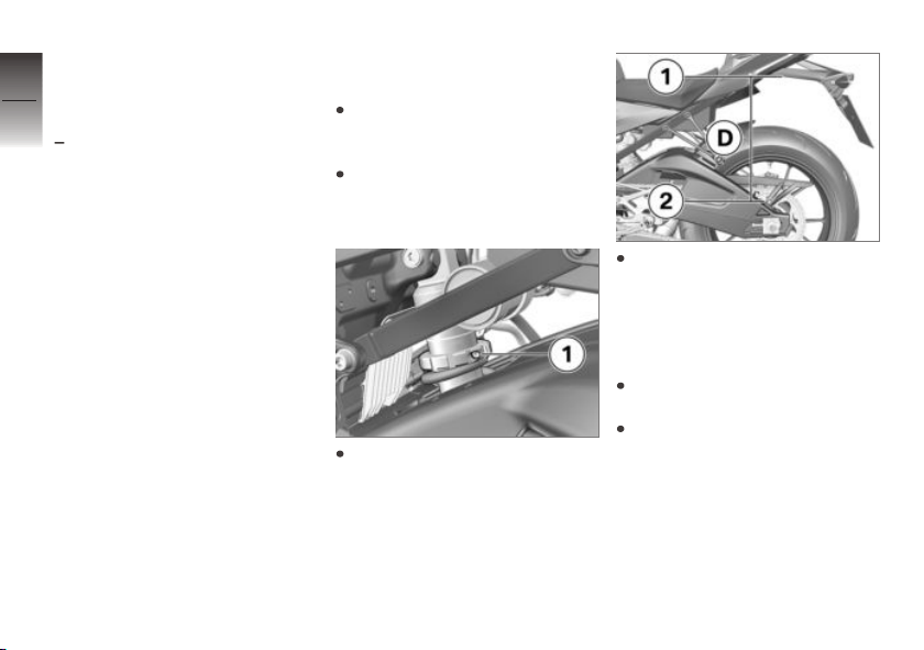
Spring preload
5
Adjustment for front
78
suspension
with Dynamic Damping Control
OE
(DDC)
Front spring preload has to
be adjusted to suit the rider's
weight. Increase spring preload
for heavier riders, decrease
spring preload for lighter riders.
Adjustment for rear
suspension
It is essential to set spring preload of the rear suspension to
z
On the race track
suit the load carried by the motorcycle. Increase spring preload when the vehicle is heavily
loaded and reduce spring preload
accordingly when the vehicle is
lightly loaded.
Adjusting spring preload
for rear wheel
Make sure the ground is level
and firm and place the motorcycle on its stand.
Make sure there is no load
on the motorcycle; remove all
items of luggage, if carried.
Use the tool from the on-board
toolkit to slacken screw 1.
Hold the motorcycle upright
(do not prop it on the side
stand) and measure distance D
from bottom edge 1 of the
number-plate carrier to screw 2
of the chain guard.
Apply the rider's weight to the
motorcycle.
With the assistance of a
second person, measure
distance D between points 1
and 2 again and calculate the
difference (negative spring
displacement) between the two
readings.
Page 81
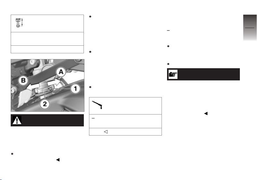
Load-dependent adjustment of spring preload
Suspension compression at
rear wheel
20...24 mm (With rider 85 kg)
WARNING
Spring preload setting and
spring-strut damping setting
not matched.
Impaired handling.
Adjust spring-strut damping to
suit spring preload.
To reduce negative spring dis-
placement (increase spring pre-
load, in other words), use the
tool from the on-board toolkit
to turn adjusting ring 2 in dir-
ection B.
To increase negative spring
displacement (reduce spring
preload, in other words), use
the tool from the on-board
toolkit to turn adjusting ring 2
in direction A.
Tighten screw 1 to the spe-
cified tightening torque.
Clamping screw to top
spring retainer
without Dynamic Damping
Control (DDC)
3 Nm
OE
Adjusting spring preload
for rear wheel
with Dynamic Damping Control
OE
(DDC)
Make sure the ground is level
and firm and place the motorcycle on its stand.
Start the engine.
NOTICE
Before adjusting spring preload
make sure there is no load on
the motorcycle; remove all items
of luggage, if carried.
Set the damping (DDC) to SOFT
for one-up riding.
5
79
z
On the race track
Page 82
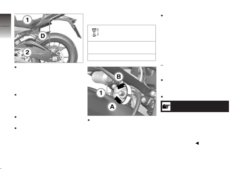
5
80
Hold the motorcycle upright,
preferably with the assistance
of a second person (do not
prop the motorcycle on the
side stand).
Measure distance D from bottom edge 1 of the number-
z
On the race track
plate carrier to screw 2 of the
chain guard.
Apply the rider's weight to the
motorcycle.
With the assistance of a
second person, measure
distance D between points 1
and 2 again and calculate the
difference (negative spring
displacement) between the two
readings.
Load-dependent adjustment of spring preload
Suspension compression at
rear wheel
20...24 mm (With rider 85 kg)
To reduce negative spring displacement (increase spring preload, in other words), use the
tool from the on-board toolkit
to turn adjusting ring 1 in direction A.
To increase negative spring
displacement (reduce spring
preload, in other words), use
the tool from the on-board
toolkit to turn adjusting ring 1
in direction B.
Adjusting spring preload
for front wheel
with Dynamic Damping Control
OE
(DDC)
Make sure the ground is level
and firm and place the motorcycle on its stand.
Start the engine.
NOTICE
Before adjusting spring preload
make sure there is no load on
the motorcycle; remove all items
of luggage, if carried.
Set the damping (DDC) to SOFT
for one-up riding.
Page 83
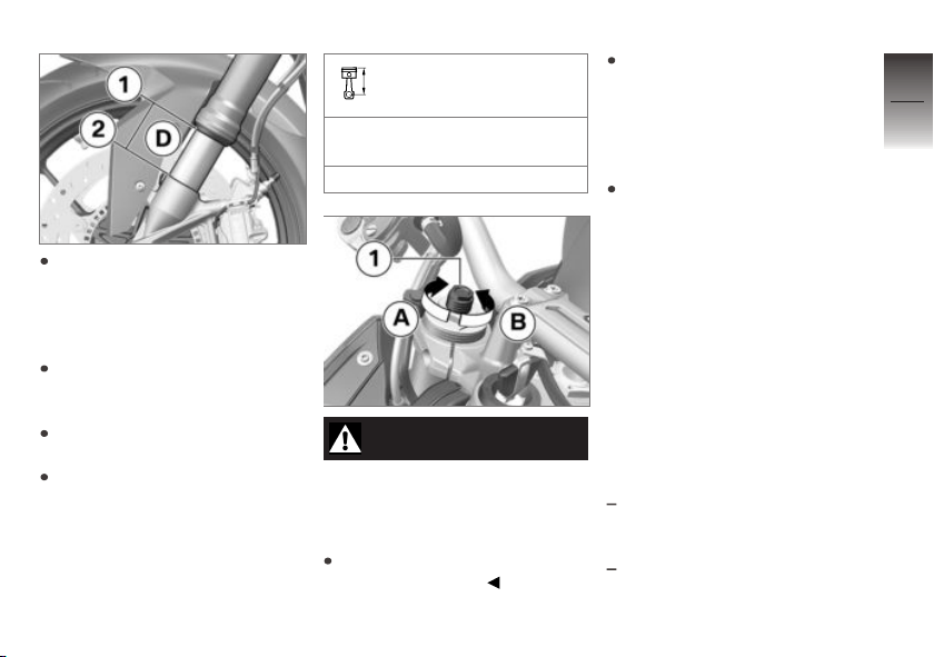
Hold the motorcycle upright,
preferably with the assistance
of a second person (do not
prop the motorcycle on the
side stand).
Measure distance D between
bottom edge 1 of the slider
tube and front axle 2.
Apply the rider's weight to the
motorcycle.
With the assistance of a
second person, measure
distance D between points 1
and 2 again and calculate the
difference (negative spring
displacement) between the two
readings.
Load-dependent adjustment of spring preload
Negative spring displacement
of front wheel
6...10 mm (With rider 85 kg)
WARNING
Spring preload setting and
spring-strut damping setting
not matched.
Impaired handling.
Adjust spring-strut damping to
suit spring preload.
To reduce negative spring displacement (increase spring preload, in other words), use the
tool from the on-board toolkit
to turn adjusting screws 1 in
direction A.
To increase negative spring
displacement (reduce spring
preload, in other words),
use the tool from the onboard toolkit to turn adjusting
screws 3 in direction B.
Damping
Correct setting for the
damping characteristic
Damping must be adapted to suit
the surface on which the motorcycle is ridden and to suit spring
preload.
An uneven surface requires
softer damping than a smooth
surface.
An increase in spring preload
requires firmer damping, a re-
5
81
z
On the race track
Page 84
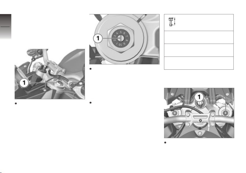
duction in spring preload requires softer damping.
5
82
Adjusting compressionstage damping for front
wheel
z
On the race track
Adjust compression-stage
damping by turning adjusting
screw 1 on the left fork leg.
To increase damping: Use the
tool from the on-board kit to
turn the adjusting screw in the
appropriate direction so that
mark 1 points to a higher reading on the scale.
To reduce damping: Use the
tool from the on-board kit to
turn the adjusting screw in the
appropriate direction so that
mark 1 points to a lower reading on the scale.
Compression stage, basic setting, front
Position 1 (comfortable setting
with rider 85 kg)
Position 3 (normal setting with
rider 85 kg)
Position 7 (sports setting with
rider 85 kg)
Adjust the rebound-stage
damping for front wheel
Adjust rebound-stage damping
by turning adjusting screw 1 on
the right fork leg.
Page 85
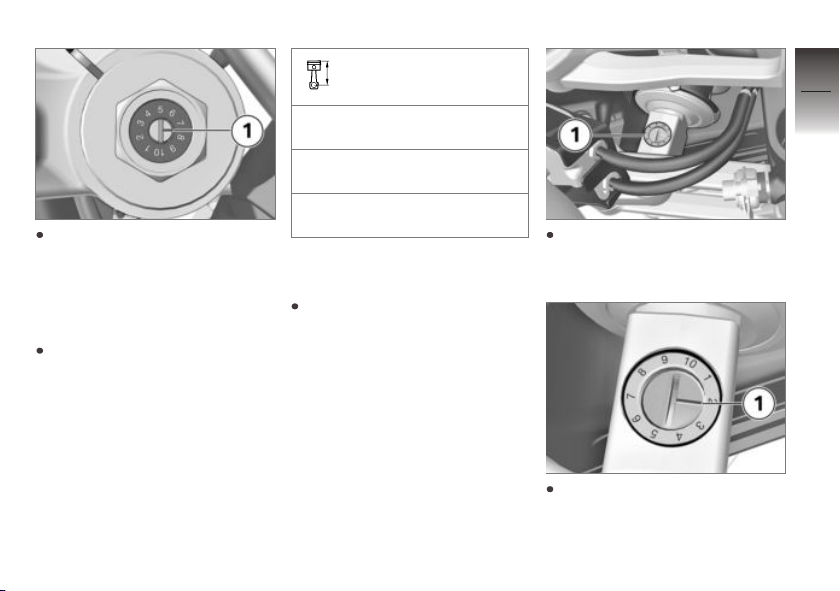
To increase damping: Use the
tool from the on-board kit to
turn the adjusting screw in the
appropriate direction so that
mark 1 points to a higher reading on the scale.
To reduce damping: Use the
tool from the on-board kit to
turn the adjusting screw in the
appropriate direction so that
mark 1 points to a lower reading on the scale.
Rebound stage, basic
setting, front
Position 1 (comfortable setting
with rider 85 kg)
Position 3 (normal setting with
rider 85 kg)
Position 7 (sports setting with
rider 85 kg)
Adjusting rebound-stage
damping for rear wheel
Make sure the ground is level
and firm and place the motor-
cycle on its stand.
Adjust compression-stage
damping by turning adjusting
screw 1.
To increase damping: Use the
tool from the on-board kit to
turn the adjusting screw in the
appropriate direction so that
5
83
z
On the race track
Page 86
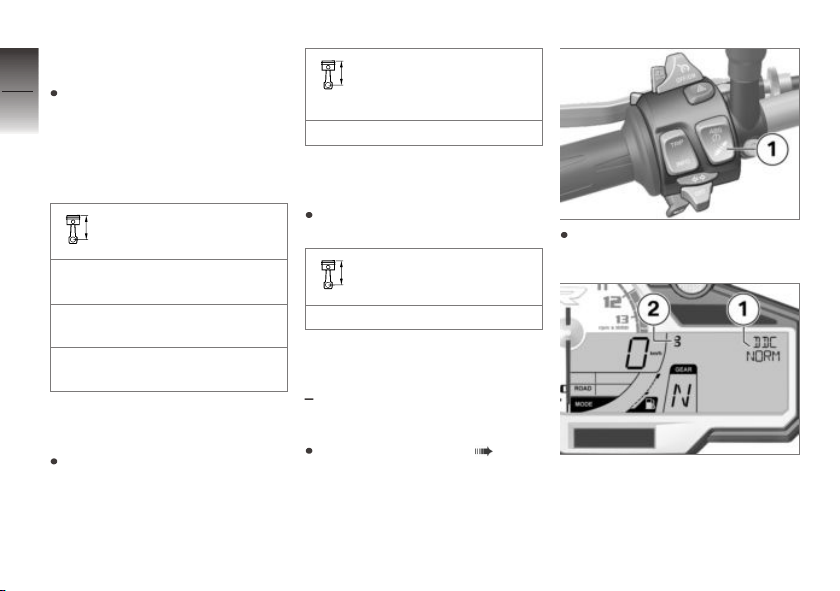
mark 1 points to a higher reading on the scale.
5
To reduce damping: Use the
84
tool from the on-board kit to
turn the adjusting screw in the
appropriate direction so that
mark 1 points to a lower reading on the scale.
Rebound stage, basic
setting, rear
Position 1 (comfortable setting
with rider 85 kg)
Position 4 (normal setting with
rider 85 kg)
z
On the race track
Position 7 (sports setting with
rider 85 kg)
Factory default settings,
front wheel
Reset the factory defaults as
stated below.
Factory default settings
for compression/rebound
stages, front
Position 3
Factory default settings,
rear wheel
Reset the factory defaults as
stated below.
Factory default setting
for rebound stage, rear
Position 4
Viewing suspension
damping with DDC
with Dynamic Damping Control
OE
(DDC)
Switching on ignition ( 40).
Press button 1 briefly to view
the current setting.
Damping is shown in area 1 and
load in area 2 of the multifunction display.
Page 87
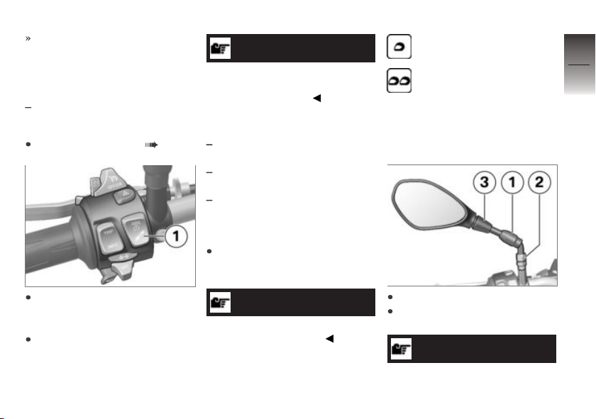
The setting shows briefly, then
disappears automatically.
Adjusting suspension
damping with DDC
with Dynamic Damping Control
OE
(DDC)
Switching on ignition ( 40).
Press button 1 briefly to view
the current setting.
To adjust damping:
Repeatedly press button 1 until
the setting you want to use
appears on the display.
NOTICE
You can adjust the damping
characteristic while the motorcycle is on the move.
The following settings are available:
SOFT: Comfortable damping
characteristic
NORM: Normal damping char-
acteristic
HARD: Sporty damping char-
acteristic
To adjust load:
Repeatedly press button 1 and
hold until the setting you want
to use appears on the display.
NOTICE
The load cannot be set while the
motorcycle is in motion.
The following settings are available:
One-up
Two-up
Removing/installing mirrors
Removing mirror
Push protective cap 1 up.
Use the tool from the on-board
toolkit to slacken nut 2.
NOTICE
When removing the right mirror, make sure that the brake-
5
85
z
On the race track
Page 88
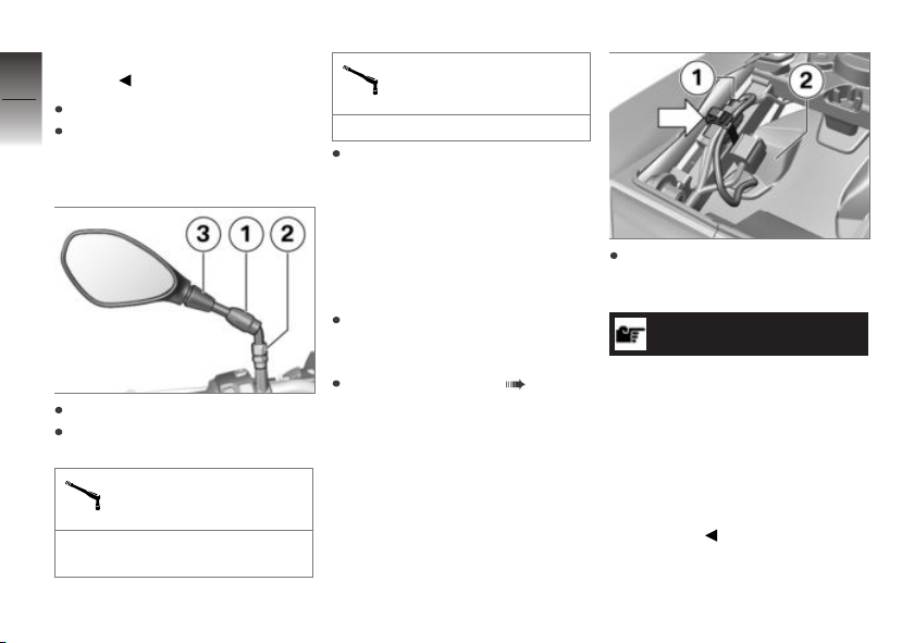
fluid reservoir remains correctly
secured.
5
Remove mirror 3.
86
Using the tool from the onboard toolkit, retighten nut 2.
Installing mirrors
z
On the race track
Install mirror 3.
Use the tool from the on-board
toolkit to tighten nut 2.
Locknut (mirror) to
clamping piece
Joining compound: Multi-wax
spray
Locknut (mirror) to
clamping piece
20 Nm
Clip protective cap 1 into position.
Removing and installing
number-plate carrier
Remove the number-plate
carrier
Make sure the ground is level
and firm and place the motorcycle on its stand.
Removing rear seat ( 61).
Remove the cable tie arrow
and disconnect plug 1 for the
number-plate carrier.
NOTICE
If the number-plate carrier is removed in preparation for a racetrack session, the electronics
detect a bulb failure and the
appropriate warning appears
on the display. Activating the
EQIP WARN LAMP function in
the SETUP MENU suppresses
this warning.
Page 89
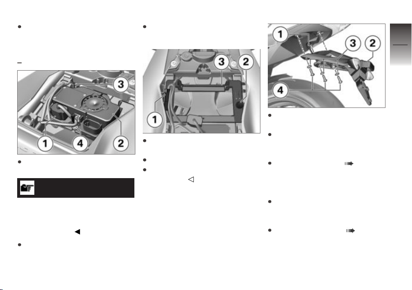
Work plug 1 with the cable
through tail bottom section 2
until clear.
with alarm system (DWA)
Disconnect plug 1 for the antitheft alarm.
NOTICE
Before disconnecting the plug for
the anti-theft alarm, check that
DWA has been deactivated in the
OE
SETUP MENU.
Remove screw 4.
Remove anti-theft alarm 2, dis-
engaging it from bracket 3.
Disengage plug 1 for the
number-plate carrier.
Remove body-bound rivet 2.
Remove bracket 3 for the anti-
theft alarm.
Remove screws 4 with washers 3.
Remove number-plate carrier 2
and work cable leg 1 out until
clear.
Install the rear seat ( 61).
Installing number-plate
carrier
Make sure the ground is level
and firm and place the motorcycle on its stand.
Removing rear seat ( 61).
5
87
z
On the race track
Page 90
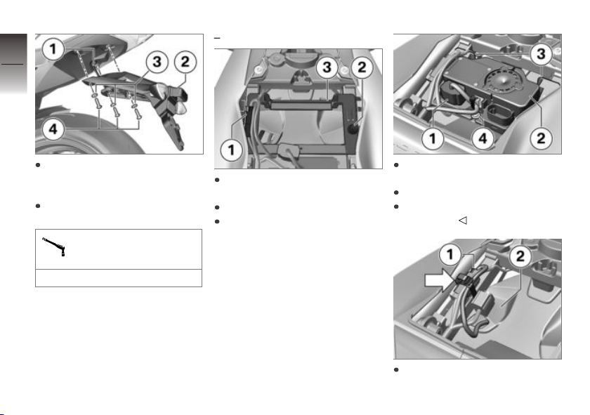
5
88
with alarm system (DWA)
OE
Hold number-plate carrier 2 in
position and work cable leg 1
into position.
Install screws 4 with washers 3.
z
On the race track
Number-plate carrier to
rear frame
5 Nm
Install bracket 3 for the antitheft alarm.
Install body-bound rivet 2.
Secure plug 1 for the numberplate carrier.
Insert anti-theft alarm 2, engaging it in bracket 3.
Install screw 4.
Connect plug 1 for the antitheft alarm.
Work plug 1 with the cable
through tail bottom section 2.
Page 91
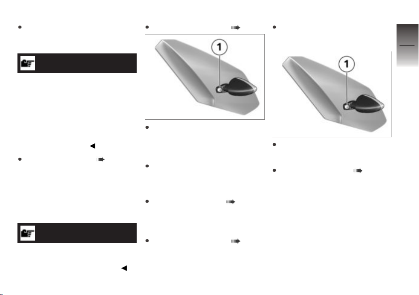
Connect plug 1, hold it in position and secure the cable
tie arrow.
NOTICE
If the warning for bulb failure is
suppressed in preparation for a
race-track session, before the
motorcycle is ridden on public
roads the warning has to be
reactivated by selecting the
EQIP WARN LAMP function in
the SETUP MENU.
Install the rear seat ( 61).
Removing and installing front turn indicators
Removing front flashing
turn indicator
NOTICE
The procedure described here
for the right side apply applies by
analogy to the left side panel.
Removing right cover ( 135).
Remove screw 1 and remove
the turn indicator. Work the
cable through the fairing side
panel.
Protect the plug on the motor-
cycle to prevent the ingress of
foreign matter.
Installing right cover ( 136).
Installing front flashing
turn indicator
Removing right cover ( 135).
Work the cable through the
fairing side panel.
Hold the flashing turn indicator
in position and install screw 1.
Installing right cover ( 136).
5
89
z
On the race track
Page 92

5
90
z
On the race track
Page 93

Riding
Safety instructions . . . . . . . . . . . . . . . . . . 92
Comply with checklist . . . . . . . . . . . . . . . 94
Starting . . . . . . . . . . . . . . . . . . . . . . . . . . . . . 94
Running in . . . . . . . . . . . . . . . . . . . . . . . . . . 98
Shifting gear . . . . . . . . . . . . . . . . . . . . . . . . 99
Brakes . . . . . . . . . . . . . . . . . . . . . . . . . . . . . 101
Parking your motorcycle . . . . . . . . . . . 102
Refuelling . . . . . . . . . . . . . . . . . . . . . . . . . . 103
Securing motorcycle for transporta-
tion . . . . . . . . . . . . . . . . . . . . . . . . . . . . . . . . 105
6
91
z
Riding
Page 94
Safety instructions
6
Rider's equipment
92
Do not ride without the correct
clothing! Always wear:
Helmet
Motorcycling jacket and
trousers
Gloves
Boots
z
Riding
This applies even to short
journeys, and to every season
of the year. Your authorised
BMW Motorrad dealer will be
glad to advise you on the correct
clothing for every purpose.
Loading
WARNING
Handling adversely affected
by overloading and imbalanced loads.
Risk of falling
Do not exceed the permissible
gross weight and be sure to
comply with the instructions on
loading.
Set spring preload, damping
characteristic and tyre pressures to suit total weight.
with tank rucksack
Note the maximum permissible
payload of the tank rucksack.
Payload of tank rucksack
≤5 kg
with rear softbag
Note the maximum payload
and the speed limit for riding
with the rear softbag fitted.
Payload of rear softbag
max 5 kg
OA
OA
Maximum permissible
speed for riding with the
rear softbag fitted to the motorcycle
max 220 km/h
Speed
If you ride at high speed, always
bear in mind that various boundary conditions can adversely affect the handling of your motorcycle:
Settings of the spring-strut and
shock-absorber system
Imbalanced load
Loose clothing
Insufficient tyre pressure
Poor tyre tread
Etc.
Page 95
Risk of poisoning
Exhaust fumes contain carbon
monoxide, which is colourless
and odourless but highly toxic.
WARNING
Exhaust gases adversely affecting health.
Risk of asphyxiation
Do not inhale exhaust fumes.
Do not run the engine in an
enclosed space.
Risk of burn injury
CAUTION
Engine and exhaust system
become very hot when the
vehicle is in use.
Risk of burn injury
When you park the vehicle
make sure that no-one and no
objects can come into contact
with the hot engine and exhaust system.
Catalytic converter
If misfiring causes unburned fuel
to enter the catalytic converter,
there is a danger of overheating
and damage.
For this reason, observe the following points:
Do not run the fuel tank dry.
Do not attempt to start or run
the engine with a spark-plug
cap disconnected.
Stop the engine immediately if
it misfires.
Use only unleaded fuel.
Comply with all specified maintenance intervals.
ATTENTION
Unburned fuel in catalytic
converter.
Damage to catalytic converter.
Note the points listed for
protection of the catalytic
converter.
Risk of overheating
ATTENTION
Engine running for prolonged
period with vehicle at standstill.
Overheating due to insufficient
cooling. In extreme cases, the
motorcycle could catch fire.
Do not allow the engine to idle
unnecessarily.
Ride away immediately after
starting the engine.
Tampering
ATTENTION
Tampering with the motorcycle (e.g. engine management ECU, throttle valves,
clutch).
Damage to the affected parts,
failure of safety-relevant functions. Damage due to tampering
is not covered by the warranty.
6
93
z
Riding
Page 96

Do not tamper with the vehicle
in any way that could result in
6
tuned performance.
94
Comply with checklist
At regular intervals, use the
checklist below to check your
motorcycle.
Always before riding off:
z
Riding
Operation of the brake system
Operation of the lights and signalling equipment
Checking clutch function
( 136).
Check the tyre tread depth
( 140).
Cases correctly installed and
luggage secured
Every 3rd refuelling stop:
without Dynamic Damping
Control (DDC)
Adjusting spring preload for
rear wheel ( 78).
OE
Adjusting compression-stage
damping for front wheel
( 82).
Adjust the rebound-stage
damping for front wheel
( 82).
Adjusting rebound-stage
damping for rear wheel
( 83).
with Dynamic Damping Control
OE
(DDC)
Adjusting spring preload for
rear wheel ( 79).
Adjusting spring preload for
front wheel ( 80).
Adjust the suspension damping
with DDC ( 85).
Checking engine oil level
( 126).
Checking front brake pad thickness ( 128).
Checking rear brake pad thickness ( 129).
Checking brake-fluid level, front
brakes ( 130).
Checking the brake-fluid level,
rear brakes ( 131).
Check coolant level ( 132).
Lubricating chain ( 137).
Checking chain tension
( 138).
Starting
Start engine
Switch on the ignition.
Pre-Ride-Check is performed.
( 95)
ABS self-diagnosis is in progress. ( 96)
ASC self-diagnosis is in progress. ( 97)
with Dynamic Traction Control
OE
(DTC)
DTC self-diagnosis is in pro-
gress. ( 97)
Select neutral or, if a gear is
engaged, pull the clutch lever.
Page 97
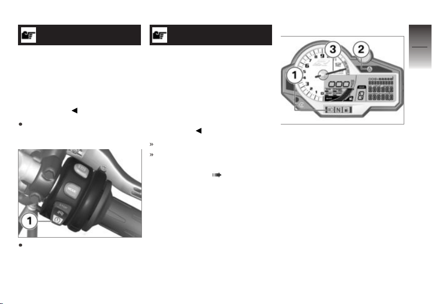
NOTICE
You cannot start the motorcycle
with the side stand extended and
a gear engaged. The engine will
switch itself off if you start it with
the gearbox in neutral and then
engage a gear before retracting
the side stand.
For a cold engine start and low
temperatures: pull clutch.
Press starter button 1.
NOTICE
The start attempt is automatically interrupted if battery voltage
is too low. Recharge the battery
before you start the engine, or
use jump leads and a donor battery to start.
See the subsection on jump
starting in "Maintenance" for
more details.
The engine starts.
Consult the troubleshooting
chart below if the engine refuses to start. ( 168)
Pre-Ride-Check
The instrument panel runs a test
of the warning lights and the revolution counter when the ignition is switched on: this is the
Pre-Ride-Check. The test is
aborted if you start the engine
before it completes.
Phase 1
Telltale and warning lights 1
light up, 'General' warning light
2 shows yellow.
Needle 3 of the revolution
counter moves all the way to the
position for maximum engine
revolutions.
All the segments in the display
light up.
Phase 2
The 'General' warning light
changes from yellow to red.
6
95
z
Riding
Page 98
Phase 3
6
The needle of the revolution
counter moves to the position
96
for zero engine revolutions.
The telltale and warning lights go
out.
The display switches to its ordinary display mode.
If a warning light does not show:
z
Riding
WARNING
Faulty warning lights.
No indication of malfunctions.
Check all the warning and telltale lights.
Have the fault rectified as
quickly as possible by a
specialist workshop, preferably
an authorised BMW Motorrad
dealer.
ABS self-diagnosis
BMW Motorrad Race ABS performs self-diagnosis to ensure its
operability. Self-diagnosis is performed automatically when you
switch on the ignition.
Phase 1
Test of the diagnosis-compatible system components with
the vehicle at a standstill.
ABS telltale and warning
light flashes.
Phase 2
Pullaway test of the system
components with diagnostic
capability.
ABS telltale and warning
light flashes.
ABS self-diagnosis
completed
The ABS symbol no longer
shows.
Check all the warning and telltale lights.
ABS self-diagnosis not
completed
The ABS function is not available, because self-diagnosis
did not complete. (The motorcycle has to reach a defined
minimum speed for the wheel
sensors to be checked: min
5 km/h)
If an indicator showing an ABS
fault appears when ABS self-diagnosis completes:
You can continue to ride. Bear
in mind that the ABS function
and the integral braking function are not available or the
functionality might be subject
to certain restrictions.
Have the fault rectified as
quickly as possible by a
specialist workshop, preferably
an authorised BMW Motorrad
dealer.
Page 99
ASC self-diagnosis
BMW Motorrad ASC performs
self-diagnosis to ensure its operability. Self-diagnosis is performed automatically when you
switch on the ignition.
Phase 1
Test of the diagnosis-compatible system components with
the vehicle at a standstill.
ASC telltale and warning
light slow-flashes.
Phase 2
Pullaway test of the system
components with diagnostic
capability.
ASC telltale and warning
light slow-flashes.
ASC self-diagnosis
completed
The ASC symbol no longer
shows.
Check all the warning and telltale lights.
ASC self-diagnosis not
completed
The ASC function is not available, because self-diagnosis
did not complete. (The motorcycle has to reach a defined
minimum speed with the engine running for the wheelspeed sensors to be checked:
min 5 km/h)
If an indicator showing an ASC
fault appears when ASC selfdiagnosis completes:
You can continue to ride. Bear
in mind that the ASC function
is not available or the functionality might be subject to certain
restrictions.
Have the fault rectified as
quickly as possible by a
specialist workshop, preferably
an authorised BMW Motorrad
dealer.
DTC self-diagnosis
with Dynamic Traction Control
OE
(DTC)
BMW Motorrad DTC performs
self-diagnosis to ensure its operability. Self-diagnosis is performed automatically when you
switch on the ignition.
Phase 1
Test of the diagnosis-compatible system components with
the vehicle at a standstill.
DTC warning light slowflashes.
Phase 2
Pullaway test of the system
components with diagnostic
capability.
DTC warning light slowflashes.
6
97
z
Riding
Page 100
DTC self-diagnosis
completed
6
The DTC symbol no longer
98
shows.
Check all the warning and telltale lights.
DTC self-diagnosis not
completed
z
Riding
The DTC function is not available, because self-diagnosis
did not complete. (The motorcycle has to reach a defined
minimum speed with the engine running for the wheelspeed sensors to be checked:
min 5 km/h)
If an indicator showing a DTC
fault appears after DTC self-diagnosis completes:
You can continue to ride. Bear
in mind that the DTC function
is not available or the functionality might be subject to certain
restrictions.
Have the fault rectified as
quickly as possible by a
specialist workshop, preferably
an authorised BMW Motorrad
dealer.
Running in
Engine
Until the running-in check (first
inspection), vary the throttle
opening and engine-speed
range frequently; avoid riding
at constant engine rpm for prolonged periods.
Try to do most of your riding during this initial period on
twisting, fairly hilly roads.
Comply with the rpm limits for
running in.
Running-in speed
<7000 min-1(Odometer reading 0...300 km)
Running-in speed
<9000 min-1(Odometer reading 300...1000 km)
no full load (Odometer reading
0...1000 km)
Note the mileage after which
the running-in check should be
carried out.
NOTICE
Engine rpm is governed by the
electronic engine management
system until the vehicle has
undergone its running-in check.
The authorised BMW Motorrad
dealer deactivates this rpm
governing function when the
motorcycle is brought in for its
running-in check.
 Loading...