


ATEM Television Studio
Blackmagicdesign ATEM Television Studio, ATEM 2 M/E, ATEM 2 M/E Production Switcher Chassis Installation And Operation Manual
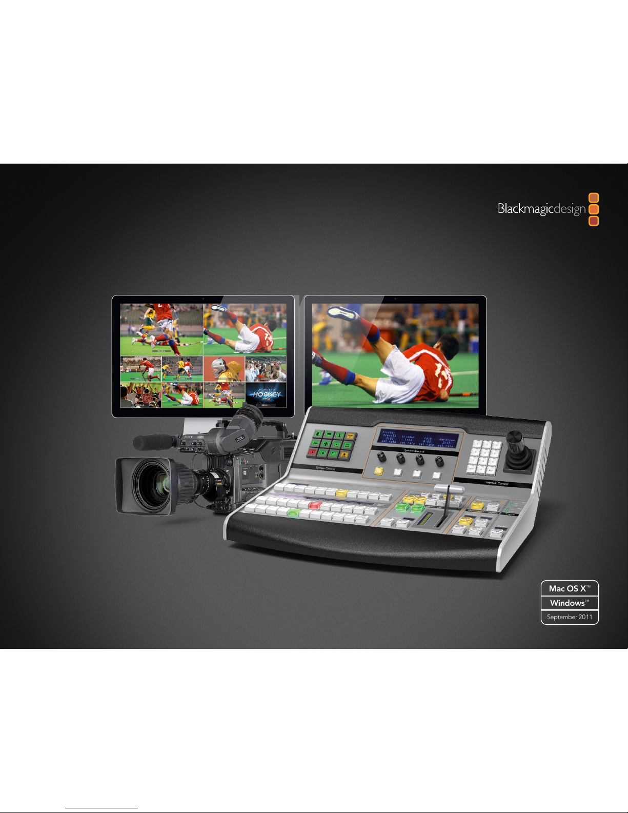
Installation and Operation Manual
ATEM Production Switchers
Windows
™
September 2011
Mac OS X
™
Welcome
Welcome to ATEM Live Production!
Thank you for purchasing an ATEM switcher for your live production work!
If you’re new to live production switchers, then you’re about to become involved in the most exciting part
of the television industry and that’s live production! There is nothing like live production and it’s so easy
to become addicted to the adrenaline rush of editing in real time while the live event unfolds before your
eyes. It’s real television the way it should be!
Previously broadcast quality live production has always been way too high in cost for most people to afford,
while affordable switchers lacked broadcast features and quality. The new ATEM switchers change this, and
you can use it for the most amazing professional live production results. We hope you get years of use from
them and have lots of fun with your live production!
Not only does this ATEM switcher include all the features and SDI connections that broadcasters demand
but you also get loads of HDMI connections so you can get started with low cost HDMI HD cameras and
televisions. This really reduces cost and lets you build your business while adding additional equipment
as you grow.
This instruction manual should contain all the information you’ll need for installing your ATEM Production
Switcher. The ATEM switcher includes a software control panel which you can run on your computer or
you can purchase a hardware based broadcast control panel separately. The computer and control panels
connect to your ATEM switcher via a network cable and you can directly connect them together without
any extra equipment!
Please check the support page on our web site at www.blackmagic-design.com for the latest version of
software for your ATEM switcher. Simply connect your computer to the ATEM switcher and the ATEM
broadcast control panel via USB to update software so you get all the latest features! When downloading
software, please register with your information so we can keep you updated when new software is released.
We are constantly working on new features and improvements, so we would love to hear from you!
Grant Petty
CEO Blackmagic Design

Contents
ATEM Production Switchers
Getting Started
Introducing ATEM 5
What is an M/E Switcher? 5
Understanding the ATEM Processor Chassis 8
Plugging in Multi View Monitoring 9
Plugging in a Control Panel 10
Installing Blackmagic ATEM Software on Mac OS X 11
Installing Blackmagic ATEM Software on Windows 7 12
Plugging in your Computer 13
Settings You Need To Check! 14
Plugging in Cameras 15
Connecting to a Network 16
Changing the Switcher Network Settings 17
Understanding the Broadcast Panel Network Settings 17
Setting the Broadcast Panel to Find the Switcher IP Location 18
Changing the Broadcast Panel Network Settings 19
Updating the Software
How to Update the ATEM Software! 20
Updating the Switcher Chassis Software 20
Updating the Broadcast Control Panel Software 21
5
20
22
24
Connecting Video Outputs
Using ATEM Software Control
Interface Overview 24
Switcher Control Panel 24
Media Manager 25
Switcher Settings 26
Using the Software Control Panel 26
Mix Effects 26
Program Bus Source Select Buttons 27
Preview Bus Source Select Buttons 27
Transition Control and Upstream Keyers 27
Downstream Keyers 29
Fade to Black (FTB) 29
Processing Palettes 29
Using the Media Manager and Media Pool 31
Changing Switcher Settings 33
Controlling Auxiliary Outputs 36
Contents
ATEM Production Switchers
42
Using the ATEM 1 M/E Broadcast Panel
Control Panel Overview 37
Using the Control Panel 37
Mix Effects 37
Source Names Display 37
Program Bus 37
Preview Bus 38
SHIFT 38
Destination Display and Select Bus 38
Transition Control and Upstream Keyers 38
Downstream Keyers 40
Fade to Black 40
System Status 41
System Control 41
Menu Buttons 41
Joystick and Numeric Keypad 41
Operating Your ATEM Switcher
Video Processing Overview 42
Internal Video Sources 42
Black 42
Color Bars 42
Color Generators 42
Media Players 43
Cut Transitions 44
Auto Transitions 46
Manual Transitions 62
Preview Transition 63
Keying on ATEM Switchers 64
Understanding Keying 64
Using Adobe Photoshop with ATEM 82
Setting up Plug-in Switcher Location 82
Preparing Graphics for Download 82
Using Auxiliary Outputs 83
Using USB 3.0 Connection 85
Blackmagic Media Express
What is Media Express? 86
Capturing Video and Audio Files 87
Playing Back Video and Audio Files 91
Browsing Media 92
Help
Warranty Information
86
37
94
95
Getting Started
5
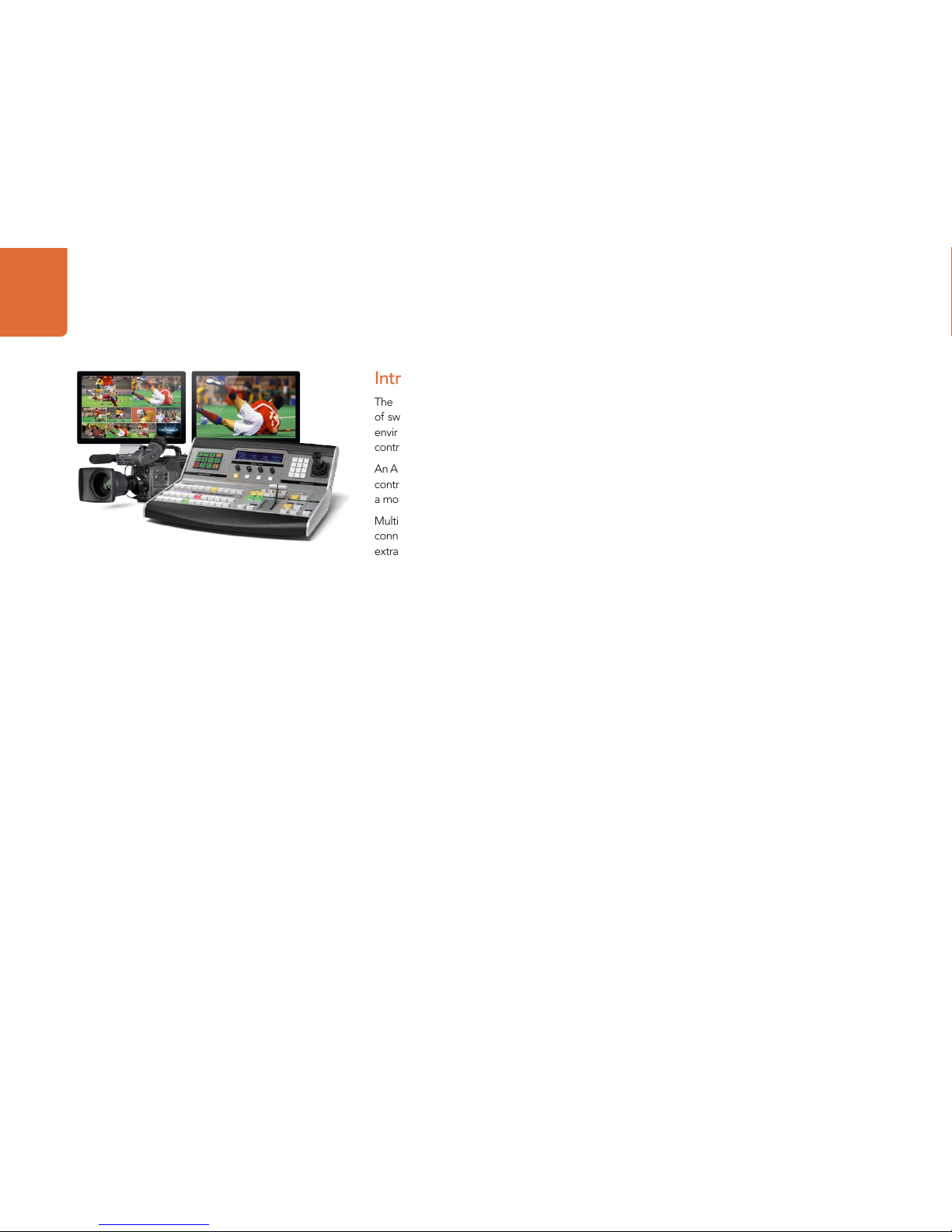
Introducing ATEM
The ATEM 1 M/E Production Switcher is a professional broadcast grade digital production switcher capable
of switching and creatively processing a variety of video sources in live video production and broadcast
environments. The switcher uses a familiar M/E (Mix Effects) based design with software and hardware
control options that provides a familiar, fast and easy to use workflow!
An ATEM production switcher only requires an ATEM production switcher chassis and the included software
control panel to get started. Then you can optionally add one or more hardware control panels if you need
a more advanced solution.
Multiple control panels can be connected to control the same switcher chassis by simple ethernet
connections. The ATEM software control panel can be installed on as many computers as you like at no
extra cost.
What is an M/E Switcher?
If you have used low cost switchers before, then these might not have used the mix effects style of operation
that’s commonly called an M/E style of operation. If you have used an M/E style switcher, then you might
want to skip ahead to install and get working with your new ATEM switcher!
When you’re starting out with a switcher for the first time, the ATEM can look a little intimidating with all its
buttons and knobs, however it's all very logically laid out so it's very simple to use!
ATEM is a true high-end broadcast switcher that operates using the M/E workflow standards used in the
broadcast industry. This means once you get familiar with how it works, you will feel instantly at home on
virtually any switcher used in broadcast today.
The M/E style of operation has been developed over decades to help eliminate errors when switching live
events and is a broadcast standard. It's extremely easy to see what's going on at any time so you don't get
confused and make mistakes. The M/E style of operation lets you check the sources you are about to switch
on air, as well as try effects before using them on air. You can see buttons for each keyer and transition, so
you instantly know what's going on and what's about to happen.
The best way to learn about how your ATEM works is to grab your switcher and play with it while referencing
this manual! You might want to jump ahead and install your switcher before reading the rest of this section!
To start, the most visible part of an M/E based control panel is the fader bar fader, and the program and
preview rows of source buttons!

Getting Started
6
The program bus source select buttons are used to hot switch sources to the program output. The source
currently on air is indicated by a button that is illuminated red. Be careful when selecting sources on this row,
as they will instantly be switched on air!
A better and more orderly way to do transitions is to select them on the preview row, and then use a
transition to cut or transition them on air.
The bottom row of buttons is the preview bus source selection. This is where you will spend most of your
time selecting sources about to go on air. This selected source is sent to the program output when the next
transition occurs. The next transition can be triggered by pushing the cut button, the auto button, or by
toggling the fader bar. You can select between a mix, dip, wipe, DVE or other transition depending what
you have selected in the transition control section.
This is a very powerful way to use a switcher, because you can select your source on the preview row, and see
it on the preview video output to confirm that you have the correct source before you select the transition
you want. You can see what's happening at all stages so it’s hard to make mistakes. Only the M/E style of
operation allows you to keep track of what's going on.
You also might notice that once your transition is complete, the sources selected on the preview and
program rows swap over. This is because the source you selected on the preview row is now the new on
air source, so it becomes selected on the program row once the transition is complete. Remember the
program row always shows what's on air.
You will also see both the program and preview buttons illuminate red when doing an auto transition, as for
a short time, they are both on air while the transition occurs.
There are multiple types of transitions available, and they can be selected in the transition control. On the
ATEM 1 M/E Broadcast Panel there are two transition type buttons. One is labeled dip/mix and the other is
labeled DVE/wipe. Hitting these buttons selects mix and wipe transitions, however pressing shift and then
selecting mix or wipe allows more types of transitions, dip and DVE. You can also select both buttons for a
stinger transition. If you are using the ATEM software control panel on your computer, all transition types
have their own button, and no shifting in necessary to select any of them. Extra details on how all these
transitions work are provided later in this instruction manual.
The other concept that is important to know about M/E style switchers, including ATEM, is the video on the
program and preview rows is technically called the background video. This is because the upstream (effects)
keyers and downstream keyers will overlay on top of this source. So you can load graphics into the keyers
and see them with the preview video and when keys are turned on, you will see the overlay on top of the
program video. This is very powerful and allows multiple layers to be built up.

Getting Started
7
Another great advantage of the ATEM M/E style of operation is you can tie keyers to the transition. This
means when you do a mix transition, you can also fade on or off keyers at the same time. This allows you to
build up a composition, and then bring the whole lot on air at the same time. This is what the next transition
buttons do, and you can select background for normal transitions, or select one or more keyers to transition
them on air.
You can even press multiple buttons on the hardware control panel to tie multiple keys and the background
at the same time. There are also dedicated downstream key tie buttons to tie downstream keyers to the
transition. Downstream keys also have dedicated cut and mix buttons and so are very flexible. Downstream
keyers are always layered over the top of everything including the transition, so are a great place to key bugs
and logos!
Finally, when your live production is finishing, it's nice to have a dedicated fade to black (FTB) control to fade
everything to black!. You can see the dedicated fade to black control on the right side of the keyboard. This
lets you fade everything to black, and helps make sure you don't miss a layer. Fade to black is at the extreme
end of the processing chain so you get a clean fade of all sources.
The last part of an M/E style switcher is the select bus. This is above the program row, and simply allows
sources to be selected for effects processing and other purposes, and there is a label above this to show
what you’re switching. The select bus is commonly used to select key inputs, and aux. outputs. It's a clean
switch, so when used to select aux. outputs, you get a clean cut.
As you can see by this quick overview, M/E style of operation allows confident live production with
good feedback on what's going on and the state of your switcher and programming at any point in your
production. Once you learn M/E style of operation, you can move between models of production switchers
with little retraining as they all work the same!
Getting Started
8
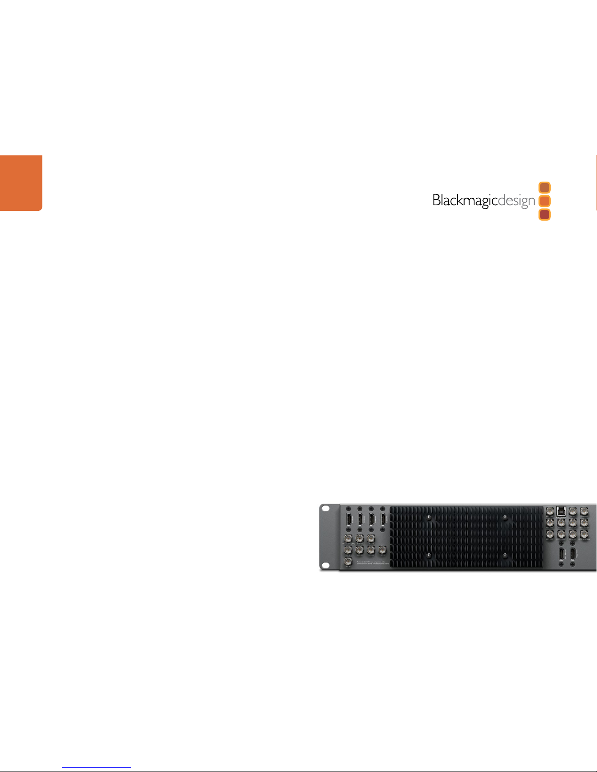
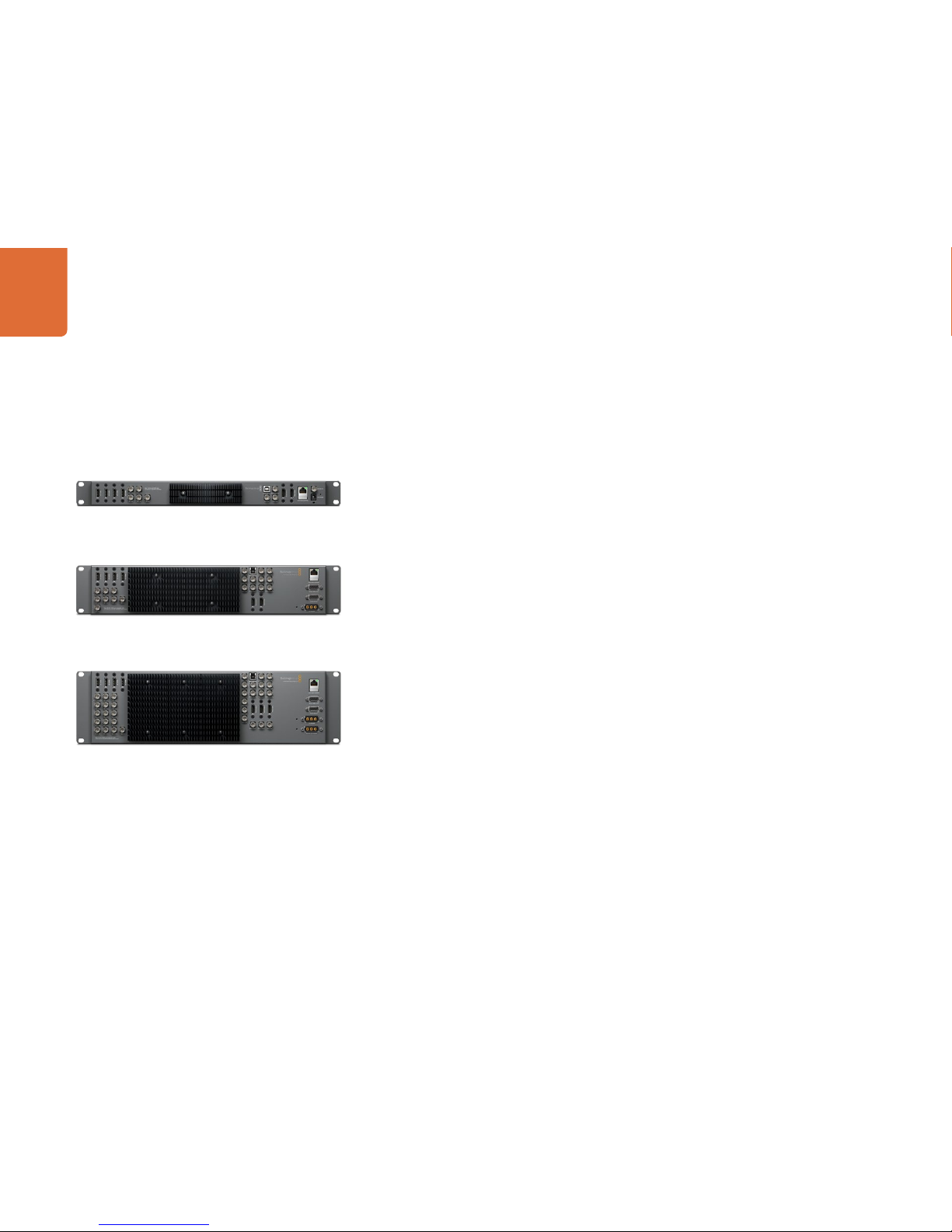
Understanding the ATEM Processor Chassis
The ATEM processor chassis provides all the video processing as well as all video input and output connectors,
connection for control panels and power connections. You use the ATEM switcher by connecting and using
various types of control panels. This allows the switcher to be located remotely, such as in machine rooms
where it's closer to the connected video devices, while the control panel can be placed in a location from
where it is easier to run production.
The Television Studio is capable of switching 6 external inputs from its SDI and HDMI input connectors.
Input 3 and 4 are selectable between HDMI and SDI, which can be set in the ATEM software control panel
settings tab.
The 1 M/E model of switcher is capable of switching 8 external inputs from its analog, SDI and HDMI input
connectors. Input 1 is selectable between the HDMI Input 1 connector and the analog component Input 1
connector and is set in the ATEM software control panel settings tab.
The 2 M/E model of switcher is capable of switching 16 external inputs from its analog, SDI and HDMI input
connectors. Input 1 is selectable between the HDMI Input 1 connector and the analog component Input 1
connector and is set in the ATEM software control panel settings tab.
The ATEM chassis mounts in a standard 19" rack. The Television Studio is only 1 rack unit high while the 1
M/E is only 2 rack units and the 2 M/E is only 3 rack units high. The ATEM chassis is very thin and so is ideal
for either fixed installation or portable use. You can mount at the front or back of a rack to save space.
When running your ATEM, you might notice the ATEM processor chassis feels warm to the touch. This is
because the internal microprocessors are connected to the rear mounted heat sink via the metal chassis.
This causes heat to spread out over the metal chassis, however your ATEM chassis is not overheating.
This design eliminates noisy fans, so is more reliable, and you won't get noise into your microphones.
ATEM 1 M/E Production Switcher Chassis
ATEM Television Studio
ATEM 2 M/E Production Switcher Chassis
Getting Started
9
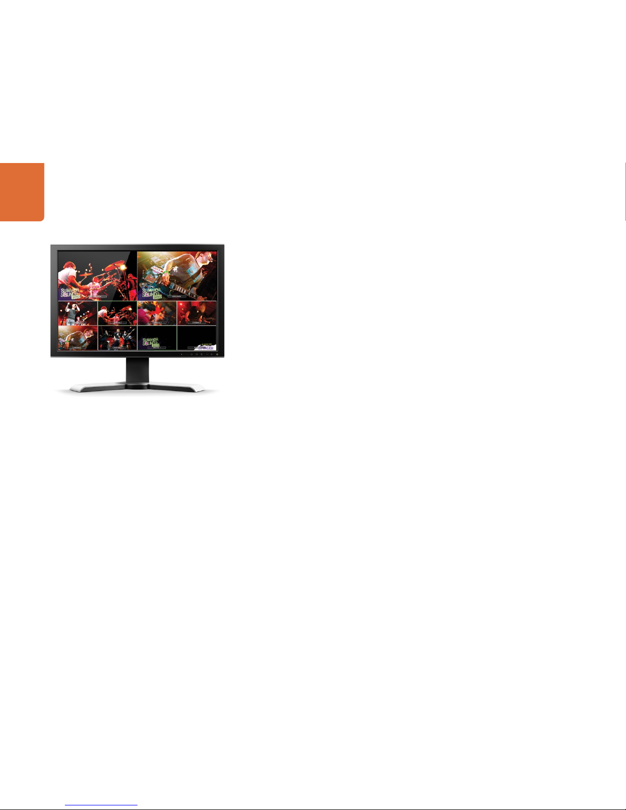
Plugging in Multi View Monitoring
The ATEM switcher chassis can be a little intimidating when first seen, because it has no controls to access,
just lots of connectors! So the first step is to plug in the power, and a monitor, to see it working!
A fantastic way to check that your ATEM is powered on and working correctly is to plug in a HDMI television
into the Multi View output on the right side of the heat sink on the ATEM rear panel. You should see 8 video
boxes at the bottom, and two larger boxes at the top, all bound by white borders. Each box will have a label.
If you see this video output, then your ATEM switcher is powered on and running fine! All you need to do
now is plug in some control panels and video sources so you can start using your switcher!
If you don't see the multi view output on your television, then check the connections and cables are correct.
You need to plug into the multi view connector on the rear of the ATEM chassis. Next check your television is
compatible with 1080i59.94 video, as your ATEM defaults to that video standard when new. If your television
is not compatible with 1080i59.94, then don't worry, as it's easy to change once we connect your computer
to the ATEM chassis.
If you still don't see the multi view on your television, then double check your power connection to make
sure your ATEM is powered on.
Getting Started
10
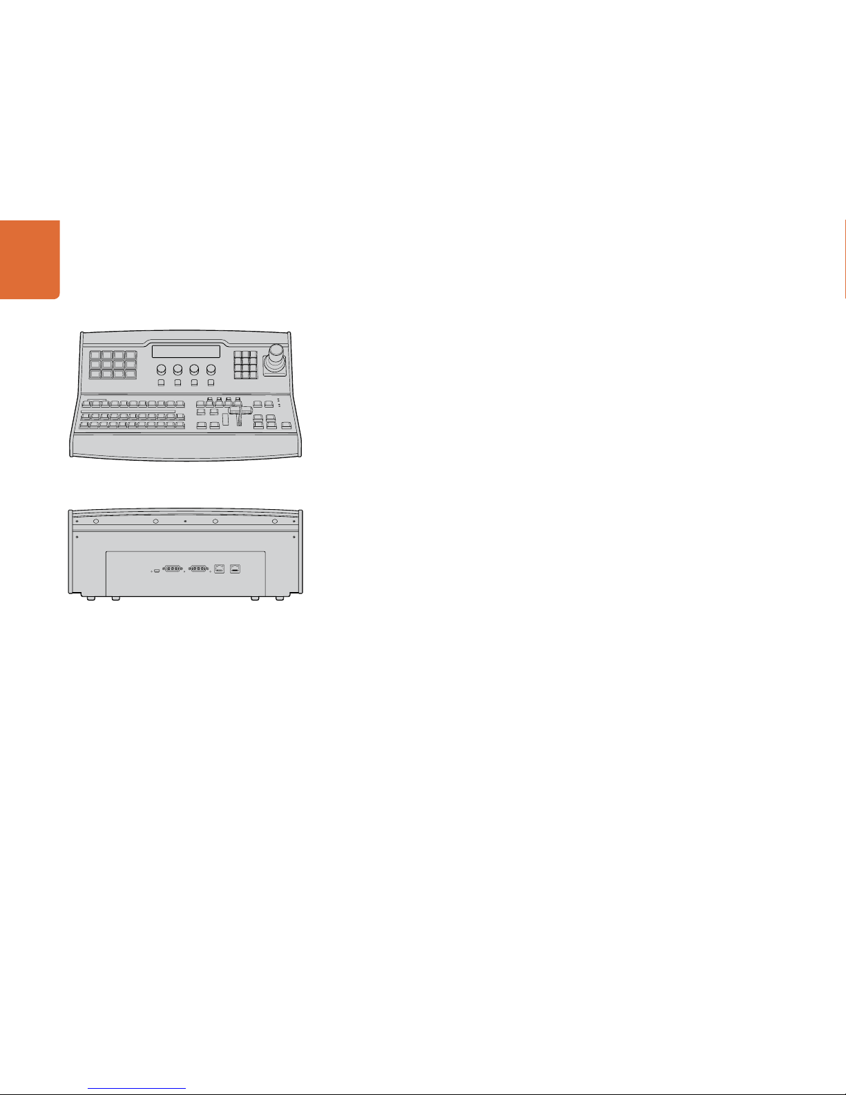
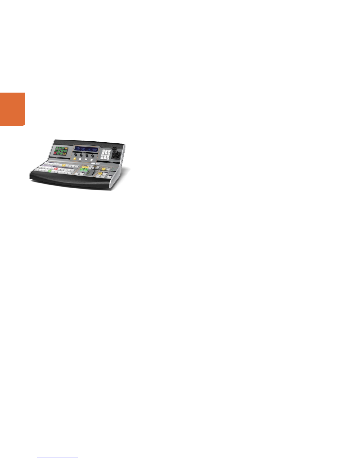
Plugging in a Control Panel
If you have purchased an ATEM Broadcast Panel, then you won't want to wait to plug in your computer, as
it's much more fun to plug in the hardware panel first!
Plugging in the ATEM Broadcast Panel is simple, because it's already set to the correct network settings to
plug into your ATEM processor chassis without any changes required.
Step 1. Plug in the power to the ATEM Broadcast Panel. If you want redundant power supplies, then you
can purchase a second power supply and plug that into the second power connector.
Step 2. Plug one end of an ethernet cable into one of the control panel’s ethernet ports. Either of the
ports will do, as there is an ethernet switch inside the panel, so both ports work the same.
Step 3. Plug the other end of the same cable into the ethernet port on the ATEM processor chassis
labeled switcher control.
If everything is working fine, you should see the lights on the ethernet port start to flicker, and the panel
should come alive with buttons illuminated, and the main display on the panel should say ATEM Production
Switcher.
If you don't see this appear, then check the ATEM processor chassis and the control panel are powered
correctly and the cables are screwed in tight.
If things are still not working, then you should make sure you are not plugged into a network, and that your
panel is connected directly to your ATEM switcher processor chassis. If this is correct, then the most likely
cause of the problem is the switcher and the chassis have different IP addresses. In this case, you will need
to check and set these as described later in this manual.
If you need to manually set the network settings, then you might need to get the assistance of a technically
minded friend who understands how to set IP addresses. By default, the ATEM processor chassis is set to a
fixed IP address of 192.168.10.240, and the ATEM Broadcast Panel is set to fixed IP of 192.168.10.10, so when
connected directly they should communicate without any problems. Go to the connecting to the network
section in this manual to see how to check and set your switcher to these addresses. Then it should work ok
with a direct connection between the panel and the switcher processor chassis.
MAIN 12V POWERBACKUP 12V POWER
USB 2.0
ETHERNET 2ETHERNET 1
Getting Started
11
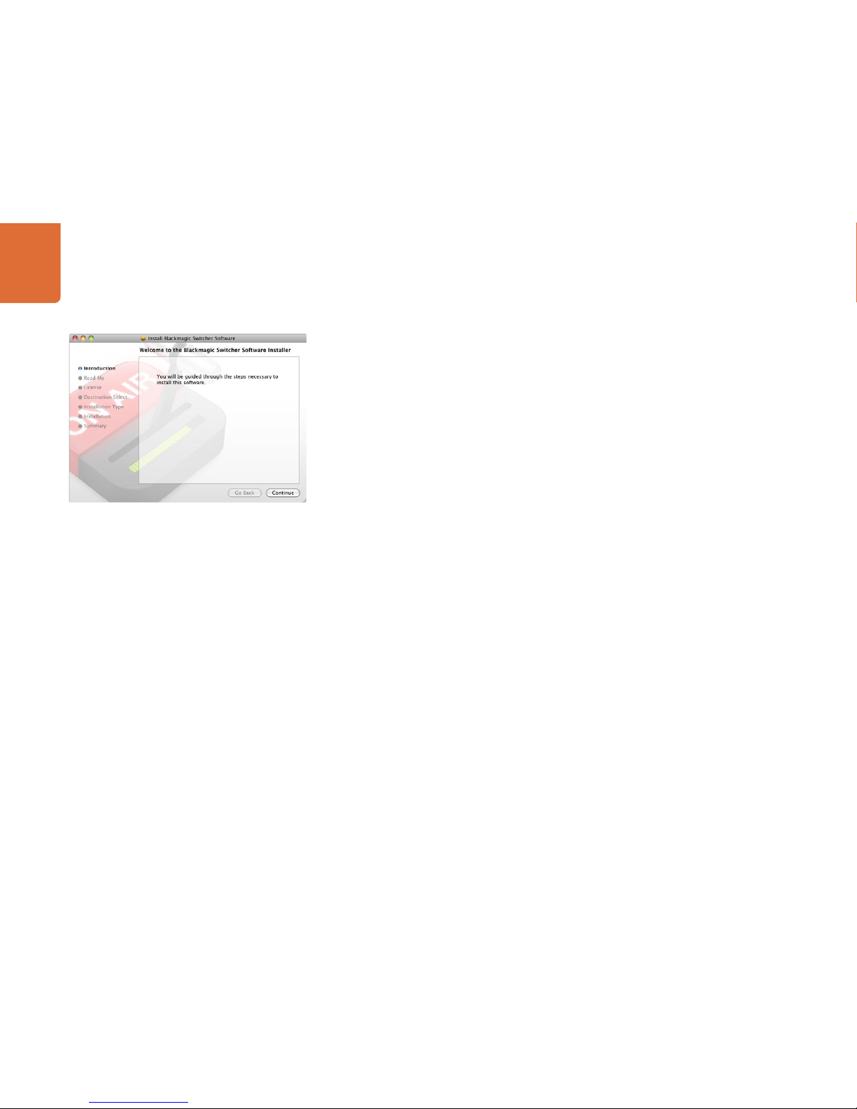
Installing Blackmagic ATEM Software on Mac OS X
Before installing any software you will need administrator privileges.
Step 1. Ensure you have the very latest driver. Visit www.blackmagic-design.com/support
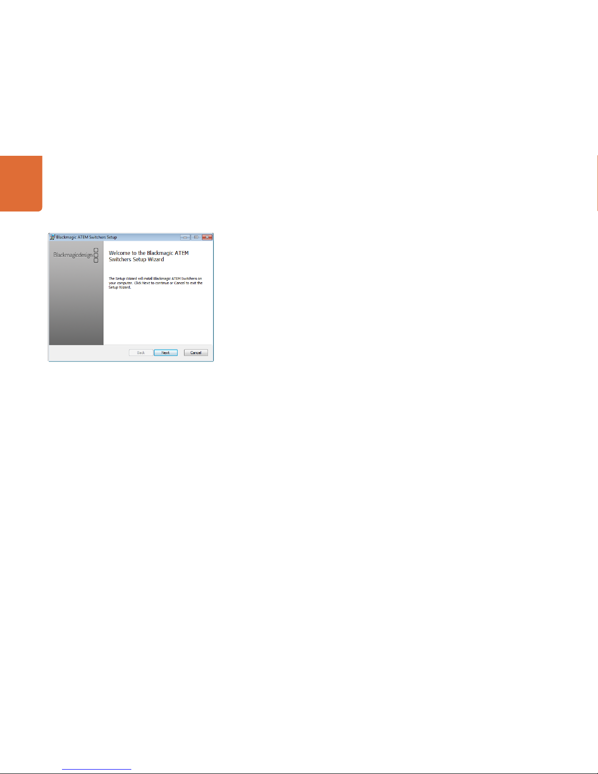
Step 2. Open the “Blackmagic ATEM Switchers” folder from the disc or downloaded disk image and
launch the “Blackmagic ATEM Switchers Installer”.
Step 3. Click Continue, Agree and Install buttons and the software will be installed on your system.
Step 4. Now restart your computer to enable the new software drivers.
Plugins and Applications that are Installed
The ATEM Switchers software installs the following components which are used by ATEM Switchers:
ATEM Software Control
ATEM Setup Utility
Blackmagic Desktop Video drivers
Blackmagic Media Express
The ATEM Switchers software also installs additional Blackmagic Desktop Video components which are
used by other Blackmagic Design capture products when installed on the same computer:
On Mac OS X, all the files needed to run your ATEM switcher will be installed into a folder called Blackmagic
ATEM Switchers in the Applications folder.
In this Blackmagic ATEM Switchers folder, you will see ATEM Software Control, which is the software control
panel for your switcher, and also allows loading graphics into the switcher media pool and changing settings.
The ATEM Setup Utility allows you to change the switcher IP address, or update the switcher and panel
software via USB. Also included in this folder is this instruction manual and some example graphics. Use the
example graphics to explore the internal media pool and keying functionality.
In the Applications folder, you will see Blackmagic Media Express which allows you to capture the Program
Output of ATEM Television Studio to H.264 files.
Follow install prompts.
Getting Started
12
Installing Blackmagic ATEM Software on Windows 7
Step 1. Ensure you have the very latest driver. Visit www.blackmagic-design.com/support
Step 2. Open the “Blackmagic ATEM Switchers” folder and launch the “Blackmagic ATEM Switchers
Installer”.
Step 3. The software will now be installed on your system. An alert will appear: “Do you want to allow the
following program to install software on this computer?” Click Yes to continue.
Step 4. You will see a dialog bubble saying “found new hardware” and the hardware wizard will appear.
Select “install automatically” and the system will find the required Desktop Video drivers. You will
then receive another dialog bubble saying “your new hardware is ready for use.”
Step 5. Now restart your computer to enable the new software drivers.
Plugins and Applications that are Installed
The ATEM Switchers software installs the following components which are used by ATEM Switchers:
ATEM Software Control
ATEM Setup Utility
Blackmagic Desktop Video drivers
Blackmagic Media Express
The ATEM Switchers software also installs additional Blackmagic Desktop Video components which are
used by other Blackmagic Design capture products when installed on the same computer:
Once the computer has restarted, all the ATEM software applications will be installed and can be accessed
from Start > Programs > Blackmagic Design.
In the ATEM Switchers folder, you will see the ATEM Software Control, which is the software control panel for
your switcher, which also allows loading graphics into the switcher media pool and changing settings. The
ATEM Setup Utility allows you to change the switcher IP address, or update the switcher and panel software
via USB. Also included in this folder is this instruction manual and some example graphics. Use the example
graphics to explore the internal media pool and keying functionality.
In the Media Express folder, you will see Blackmagic Media Express which allows you to capture the Program
Output of ATEM Television Studio to H.264 files.
Follow install prompts.
Getting Started
13
Plugging in your Computer
You can plug your computer directly into the ATEM switcher so you can control the switcher, load the media
pool with graphics and clips, and change switcher settings.
You will need to connect a computer otherwise you cannot change settings such as the switcher video
standard, as well as down conversion modes, input video connections and labels, as well as customizing
the multi view.
Connecting your computer is easy and after installing the ATEM Switcher Software simply follow the
directions below:
Step 1. Connect an Ethernet cable from the chassis ethernet port labeled Switcher Control to the Ethernet
port of your computer.
If you have a hardware panel installed, and already have this connected to your ATEM, then plug
your computer into the second ethernet port on your hardware panel instead. Now the computer
will talk via your panel to the switcher, and both the hardware panel and this software control
panel can be operated in parallel.
Step 2. Ensure your ATEM switcher is powered on.
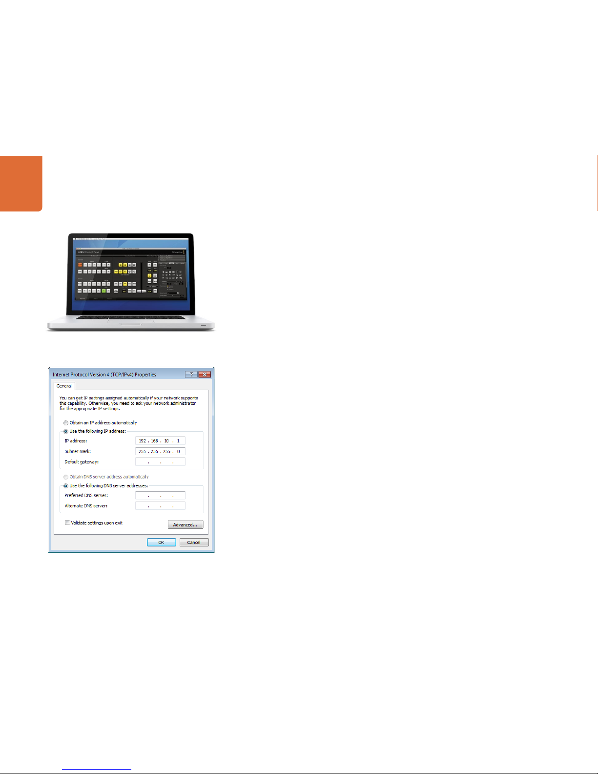
Step 3. In the network settings on your computer, enable ethernet, and set the IP address setting to
manual. Then enter the IP address 192. 168.10.1.
Now when you run your ATEM Software Control you should see the buttons on the control tab light up and
show the switcher state after a slight pause.
If you’re more technically minded and want to connect your ATEM switcher to your network, then you will
need to change the network settings on your ATEM switcher and control panel. Information on how to do
this is available in the next section. You will need to manually set the IP address for the switcher chassis as
well as all control panels to match your network IP address range. Your ATEM switcher defaults to a fixed
IP address of 192.168.10.240 when shipped and, by using the ATEM Setup Utility, you can customize the IP
address for your custom network configuration.
Set IP Address for your Computer
Getting Started
14
Settings You Need To Check!
Now you have the software control working, you need to change some settings to use your ATEM switcher.
The changes are made in the settings tab of the ATEM Software Control and the most critical settings are
listed below:
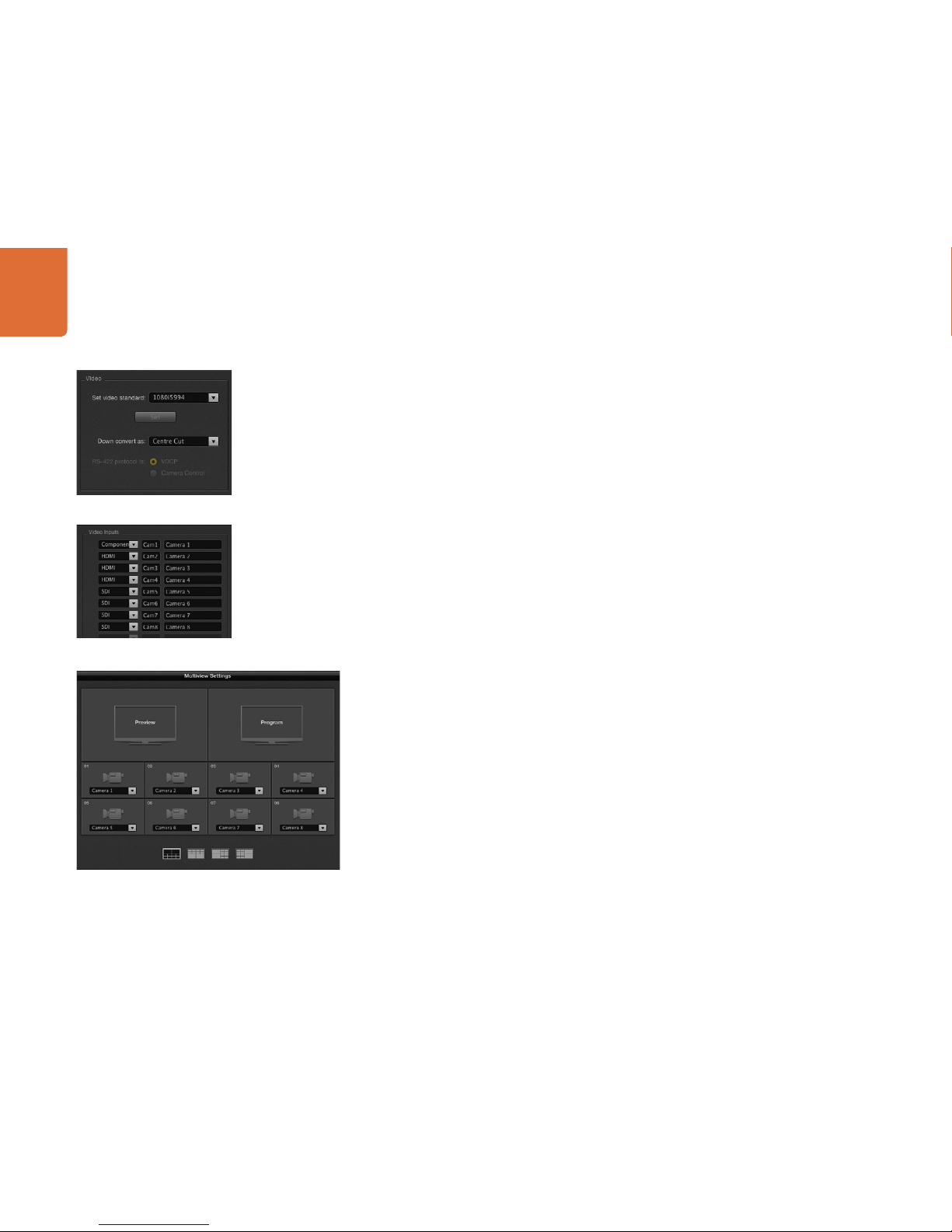
Check 1. Set the switcher video standard
ATEM defaults to 1080i59.94 when purchased, however you might want to select another video
standard if you’re working in Europe or Asia. 1080i59.94, 720p59.94 and NTSC is common in the
US and Japan, while in Europe and Asia, 1080i50, 720p50, or PAL is more common.
You need to make sure all your cameras and any connected HDMI devices are also set to the
same video standard, or they won't be visible on the switcher video inputs. This means you need
to standardize on a specific video standard for all your equipment. This is generally quite easy,
as countries have standards for their HD broadcasts and all equipment sold in these countries
matches this standard or at the very least can be switched between standards. When all video
standards are matched, you should see connected devices show up in the multi view video input
windows.
Check 2. Set and label the video input settings
Different models of ATEM switchers allow some inputs to change between multiple connections
on the rear panel. For example on the ATEM 1 M/E Production switcher model, input 1 can be
switched between HDMI and analog component.
While you’re setting inputs, you might also want to change the input labels. These labels appear
on the multi view and the hardware panel. There are two labels to change: a long label used in
software, and the short label that's limited to 4 digits and used in the hardware control panel.
Check 3. Customize the multi view
There are 8 input views in the multi view, and you can select from a range of external and internal
sources to display on these views. Simply click the menus to select what you want on each view. If
you don't have 8 cameras on your job, then you can even select media players, color generators,
or aux. outputs on these views. It's extremely flexible, and you can also change the multi view
layout to suit your preference.
Set Video Inputs and Labels
Set Video Standard
Customize the Multi View
Getting Started
15
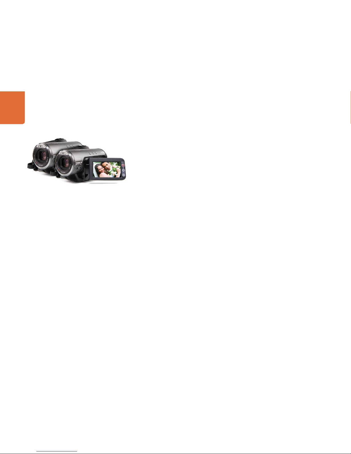
Plugging in Cameras and Other Video Sources
Now you’re ready to plug in cameras! All you need to do is connect a cable from the camera video output,
either HDMI or SDI, and then connect it to an input on the ATEM switcher chassis.
Each connector on the rear chassis has an input label so you can see what camera is what input when viewed
on the multi view and the control panel. If all your cameras are using the same video standard as set in your
switcher, you will see each camera appear as you plug them in.
You don't need to worry about genlock for cameras, because each input of your ATEM switcher has a
full frame re synchronizer. If the ATEM switcher detects at any time that a video source is out of sync, it
will automatically enable the frame sync so the input is clean for use. The frame sync function also allows
consumer cameras to be connected to your ATEM, and using consumer cameras is a great way to get
started because the latest HDMI based consumer HD cameras are now very affordable, and give quite
nice HD. This lets you spend your money on more cameras, and then as you grow, you can start adding
professional SDI based cameras.
If you’re plugging in a computer to the HDMI inputs of the ATEM switcher, then be sure that the monitor
settings on the computer are set to the correct resolution and frame rate. If you’re using 1080i video, then
your monitor needs to be 1920 x 1080 resolution. If you’re running 720p on your switcher, then your monitor
needs to be set to 1280 x 720 in resolution. If you are using NTSC then your monitor needs to be 720 x 486.
If you are using PAL then your monitor needs to be set to 720 x 576. The frame rates also need to match.
It's important to know that HDMI cable quality can vary, so we recommend buying good quality cables, and
high end video resellers will stock a range of high quality cables. Good quality cables will help eliminate
unwanted sparkle or glitches in HDMI video inputs.
If you don't see video on a HDMI video input, even though you have a device connected, then you might
want to check if the HDMI device you have connected uses HDCP content protection. This content
protection actually encrypts the video data in the HDMI video cable, so the manufacturer does not allow
the content to be seen on anything other than a television, so you won't be able to see images from these
devices. Devices with HDCP content protection include DVD payers, and set top box's.
In general, cameras and computers don't have content protection, so you should not have any problems
connecting these devices. Some gaming consoles don't include HDCP content protection, however
generally these are only the developer versions of these gaming consoles. Using the analog component
input on your ATEM switcher to connect devices is a good work around in these situations.
Please always be sure you have copyright ownership before using content, or displaying content publicly.
Getting Started
16
Connecting to a Network
If you want to connect your ATEM switcher to a larger ethernet network, then you will most likely need
to change the network settings on your ATEM switcher. Most people simply plug their computer and
control panel direct to the ATEM chassis, however in some situations it can be very powerful to connect
via your network!
Your ATEM ships from the factory with settings to allow hardware control panels to simply be connected
directly with an ethernet cable. However your ATEM supports full ethernet IP protocols so you can place
your switcher and panel on your network or anywhere on the planet using the internet.
However it's worth noting that if you use your ATEM on a network, then you’re also increasing the complexity
of the connection between your control panel and the switcher, so there is possibly a greater chance of
something going wrong. However ATEM can be used when plugged into a switch, and even via most VPN's
and over the internet.
To allow communication over ethernet, the IP addresses of the switcher chassis, broadcast panel and any
computer's running the ATEM Software Control Panel need to be configured correctly. The IP address used
for each device will depend on the IP address range of the network you’re plugging into.
The ATEM switcher chassis always needs a fixed IP address so control panels have a stable location to
connect to. This means you need to find a free fixed IP address in the range of your network that you
can use.
The control panels can be set to DHCP or fixed IP addresses. Generally when used on a network, the
control panel would be selected to DHCP, so it is automatically assigned an IP address when connected to
the network.
For all devices to communicate, they must share the same IP address subnet, which means the first 3 fields
in the IP address need to be the same. Each device must also use a unique IP address.
Please remember to set all devices to the correct IP address so they can all communicate. You will need to
set the IP address of the ATEM Production Switcher via USB using the ATEM Setup Utility. You will need to
set the DHCP or fixed IP mode on the ATEM Broadcast Panel and if using a fixed IP address on the panel,
set the IP address on the panel. You will also need to set the panel, switcher address to the new IP address
you have just set for the switcher.
Lastly, you need to ensure your computer is connected and working on your network. Then when you launch
the ATEM Software Control application, you will be prompted automatically to enter in an IP address for
the switcher if ATEM Software Control cannot communicate with the ATEM processor chassis. Use the IP
address you just entered in for the switcher processor chassis. Then the ATEM Software Control can find the
switcher and communicate.
Getting Started
17
Changing the Switcher Network Settings
The switcher network settings are changed using the ATEM Setup Utility via USB. Please follow the steps
below:
Step 1. Connect the switcher chassis via USB, to the computer running the ATEM Setup Utility software.
Step 2. Launch the ATEM Setup Utility software.
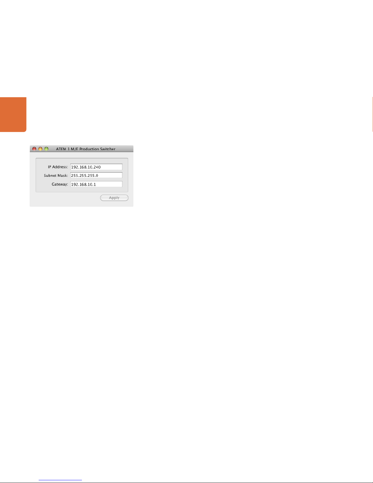
Step 3. The switcher's current IP address and other settings will be displayed in the window. If you only
want to check the IP address and not change it, you can simply quit ATEM Setup Utility.
Step 4. To change the IP address or any other settings, simply edit the numbers and then select apply.
Step 5. A dialog box will prompt you to please power cycle your ATEM switcher. Turn off and on the
power on the switcher and then press OK.
Understanding the Broadcast Panel Network Settings
A broadcast panel's network settings are configured from the network setup menu in the broadcast panel's
system control. Along with its own IP address, the broadcast panel also needs to be configured with the
network location of the switcher, so that communication between the two devices can be established over
the ethernet connection. If the broadcast panel's network settings are correctly configured, you will see the
panel light up and buttons turn on so you can control the switcher.
If the broadcast panel is displaying a message looking for the switcher, then you will need to set the
broadcast panel's network settings so that the broadcast panel and switcher share the same subnet, and
the network location to which the broadcast panel is trying to connect, matches the switcher's IP address.
ATEM Setup Utility Connects via USB

Getting Started
18
Setting the Broadcast Panel to Find the Switcher IP Location
To set the network location of the switcher on the broadcast panel, so the panel can find the switcher and
communicate, simply follow these steps:
Step 1. When there is no communication with the switcher, the NETWRK SETUP menu will appear on the
broadcast panel system control. Select the NETWRK SETUP menu button.
Step 2. Select the SWITCHR IP menu button and use the knobs or the numeric keypad to edit each field
as required.
Step 3. When a field is changed, SAVE and REVERT menu buttons become available. Select SAVE to save
the changed IP address, or REVERT to ignore the changes and revert to the currently stored IP
address.
Step 4. If the switcher IP address setting is changed, selecting SAVE will apply the changes and the
broadcast panel will attempt to establish communication with the switcher using the new IP
address.
This does not change the IP address of the switcher itself. It just changes where the control panel is looking
to find the switcher. If the control panel cannot find the switcher, then you might need to check the switcher
processor to see if it's been set correctly. To change the IP address of the switcher, connect the switcher via
USB to a computer and run the ATEM Setup Utility software as described previously in this manual.
Home Menu
ATEM 1 M/E Production Switcher
Panel IP Address: 192.168.10.10
Connecting to 192.168.10.240...
Control Panel Connected OK
Control Panel Not Connected
Getting Started
19
Changing the Broadcast Panel Network Settings
Because the broadcast panel is also on the network and communicating with the switcher processor chassis,
it also has network settings so it can connect to the network. These settings are different to the switcher IP
address, which is just where the panel is looking to find the switcher. The panel network settings can be
changed by following the steps below:
Step 1. On the broadcast panel system control menus, select the NETWRK SETUP menu button.
If the broadcast panel has already established connection to the switcher, you can access the
NETWRK SETUP menu from the HOME menu by pressing the SHIFT and CUT/FILL buttons
simultaneously. This will reveal the NETWRK SETUP menu button so you can select the network
settings.
Step 2. The broadcast panel's current IP address, net mask and gateway information is displayed.
Step 3. The next step is to decide if you want the panel to use a fixed IP address or to be automatically
assigned an IP address from a DHCP server. Select PANEL DHCP to set this using the soft keys on
the main display.
If you’re connecting direct to a switcher without a network, then you won't have a DHCP server
to assign an IP address automatically, so you will want to select fixed. ATEM Broadcast Panels are
delivered with a fixed IP address set to 192.168.10.10, for a direct connection.
However if your network has lots of computers that automatically assign IP addresses via DHCP,
then you can also select DHCP on the panel so the panel can get its network information
automatically. This is possible on the panel, and it's only the switcher chassis itself that always
requires a fixed IP, as the switcher needs to be found by the control panels at a known fixed
address on your network.
If you select DHCP, your network settings will be complete because the panel network settings
will be obtained from the network automatically.
Step 4. If you have elected to use a fixed IP address, you now need to set this IP address by selecting the
PANEL IP menu button and use the knobs or the numeric keypad to edit each field as required.
Changing this IP address may cause the panel to lose communication.
Step 5. If the subnet mask and gateway address need to be set, then select the relevant buttons on the
system control buttons to set and use knobs or the numeric keypad to edit.
Step 6. When any settings have been changed, SAVE and REVERT menu buttons will become available.
Select SAVE to save the changes to the new network settings, or REVERT to ignore the changes
and revert to the current network settings.
Change Network Settings from the System Control
Updating the Software
20
How to update the ATEM Software!
From time to time Blackmagic Design will release new software for your ATEM switcher, with new features,
bug fixes, and increased compatibility with third party software and video devices.
To update your ATEM switcher with new software, you need to use the ATEM Setup Utility to connect to
the ATEM processor chassis and panels via USB. This utility always checks the switcher software and lets you
know if there is new software.
Always update all your equipment at the same time so it's all running the same version of software.
First, download the latest Blackmagic ATEM Switcher software and install it on your Mac or PC using the
instructions listed previously in the Installing Software section of this manual. Once installed, the new
software for your ATEM processor chassis and broadcast panel will be included in the ATEM Setup Utility.
Updating the Switcher Chassis Software
Step 1. Connect the switcher chassis via USB to your computer. The switcher chassis is equipped with
a USB connector which can be connected to a computer's USB 2.0 or USB 3.0 port using a
USB cable.
When upgrading software, make sure the switcher is the only ATEM device connected via USB to
the computer running the setup utility software. If more than one ATEM device is connected, the
switcher may not be recognized.
Step 2. Launch the ATEM Setup Utility software.
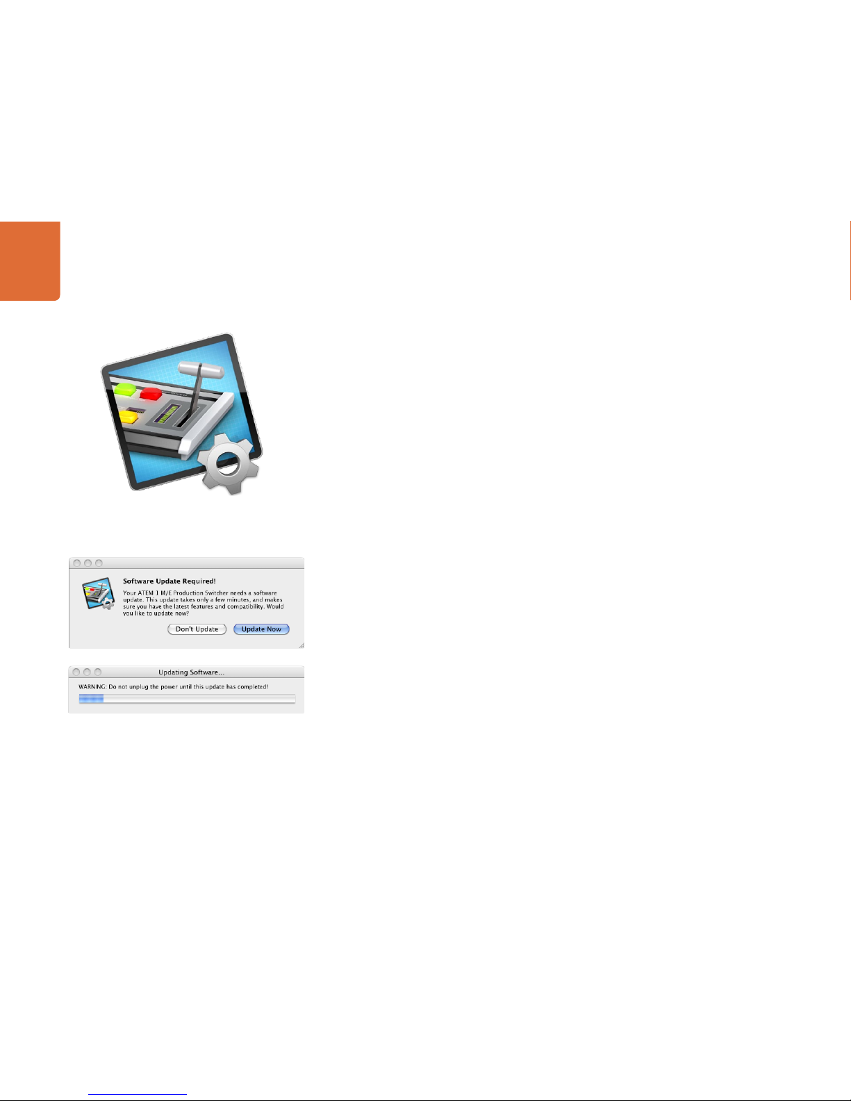
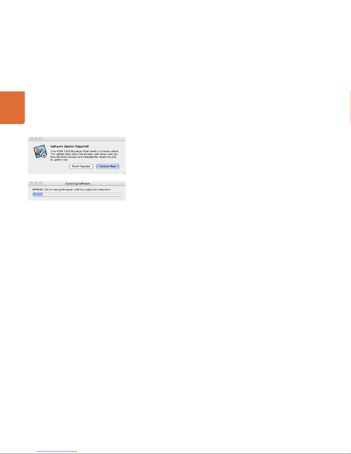
Step 3. If the switcher software requires updating, you will be prompted by a window asking if you would
like to update the software. Select Update Now to initiate the update process. The update process
may take a few minutes. Do not unplug power from the switcher during the software update.
Step 4. Once the software update is complete, a window will prompt you to cycle power on the switcher.
Select OK and cycle power on the switcher.
ATEM Setup Utility
Updating the Software
21
Updating the Broadcast Control Panel Software
Step 1. Connect the broadcast panel via USB to your computer. The broadcast panel is equipped with
a USB connector which can be connected to a computer's USB 2.0 or USB 3.0 port using a
USB cable.
When upgrading software, make sure the broadcast panel is the only ATEM device connected
via USB to the computer running the setup utility software. If more than one ATEM device is
connected, the panel may not be recognized.
Step 2. Launch the ATEM Setup Utility software.
Step 3. If the broadcast panel software requires updating, you will be prompted by a window asking
if you would like to update the software. Select Update Now to initiate the update process.
The update process may take a few minutes. Do not unplug power from the panel during the
software update.
Step 4. Once the software update is complete, a window will prompt you to cycle power on the broadcast
panel. Select OK and cycle power on the broadcast panel.

Connecting Video Outputs
22
There are multiple video outputs on your ATEM switcher, and they can be used to connect to a wide range
of video equipment, in all kinds of locations. ATEM includes SDI, HDMI and analog component, plus SD SDI
and composite video outputs, so you should be able to connect to equipment at any location. Descriptions
of each output connection are listed below.
SDI Program Output
This SDI output switches between SD and HD, and outputs the main program video output of the ATEM
switcher. It can be connected to any SDI based video device. The audio on this output is embedded from
the audio inputs on the ATEM switcher chassis or the ATEM audio break out cable.
HDMI Program Output
Similar to the SDI program output, this output switches between SD and HD of the main program video
output of the switcher. It can be connected to televisions, video projectors or even Blackmagic Design's
H.264 Encoder or HyperDeck Shuttle. The audio on this output is embedded from the audio inputs on the
ATEM switcher chassis or the ATEM audio break out cable.
Component Video Program Output
These three BNC connectors output analog component video that switches between SD and HD from the
main program output of the ATEM 1 M/E and 2 M/E production switchers. This output can be connected
to older analog equipment, encoders and video projectors for greater compatibility with equipment you
might be forced to use on location.
Standard Definition SDI Program Output
This output is down converted from high definition video and always outputs the program video feed as
standard definition on the ATEM 1 M/E and 2 M/E production switchers. This output is perfect for connecting
to older standard definition equipment or even when you need to generate simultaneous streams to master
or broadcast in both SD and HD at the same time. When running SD this output will be the same as the
program output. The audio on this output is embedded from the analog audio inputs on the ATEM audio
break out cable.
Composite NTSC/PAL Program Output
This output is down converted from high definition video and always outputs the program video feed, as
standard definition NTSC or PAL composite video, on the ATEM 1 M/E and 2 M/E production switchers.
Some locations might have old televisions or video equipment, and this composite output means you can
connect direct to these systems.

Connecting Video Outputs
23
Multi View HDMI Output
This HDMI output is always high definition and includes 8 video input views, as well as preview and program
views. Tally is included with red for sources on air, and green for sources selected on the preview bus. You
can connect this output to televisions and computer monitors with HDMI connections.
Multi View SDI Output
This SDI output is always high definition and includes 8 video input views, as well as preview and program
views. Tally is included with red for sources on air, and green for sources selected on the preview bus. You
can connect this output to televisions and professional monitors with SDI connections.
Auxiliary SDI Outputs
The ATEM 1 M/E and 2 M/E production switchers have auxiliary outputs that match the video standard and
switch between SD and HD. They can be routed from all internal and external video feeds. You can select
these outputs to be program feeds if you need more program outputs from your ATEM, or you can select
other sources such as clean feeds that include program video, without down stream keying, or even specific
video inputs. Aux. outputs are perfect for driving video screens on stage, or other feeds in venues where you
can independently control what these viewers see. Aux. outputs switch cleanly and can be used as little cut
only switchers independent of the main program outputs. The audio on these outputs is embedded from
the analog audio inputs on the ATEM audio break out cable.
USB 3.0 Output
The USB 3.0 output, available in the ATEM 1 M/E and ATEM 2 M/E Production Switcher can be used to
capture video direct to a Windows PC for real time mastering to file or for waveform monitoring. When
encoding software is used, you can also stream over the internet. ATEM switchers include Media Express
software for recording from this output, as well as Blackmagic UltraScope software for waveform monitoring.
The USB 3.0 output is connected to the Aux. 1 output so you can customize what feed you send to the USB
3.0. This lets you record clean feeds, or other sources based on the needs of your job. The audio on this
output is embedded from the analog audio inputs on the ATEM audio break out cable.
USB 2.0 Output
The ATEM Television Studio has a USB 2.0 output which can be used to capture an H.264 compressed
master file of your program. ATEM switchers include Media Express software for recording from this output.
The audio on this output is embedded from the AES/EBU input.
Preview SDI Output
This output shows the source selected on the preview bus on the switcher, as well as preview transitions.
This output is perfect when you want to use a full resolution preview monitor. The audio on this output is
embedded from the analog audio inputs on the ATEM audio break out cable.
Using ATEM Software Control
24
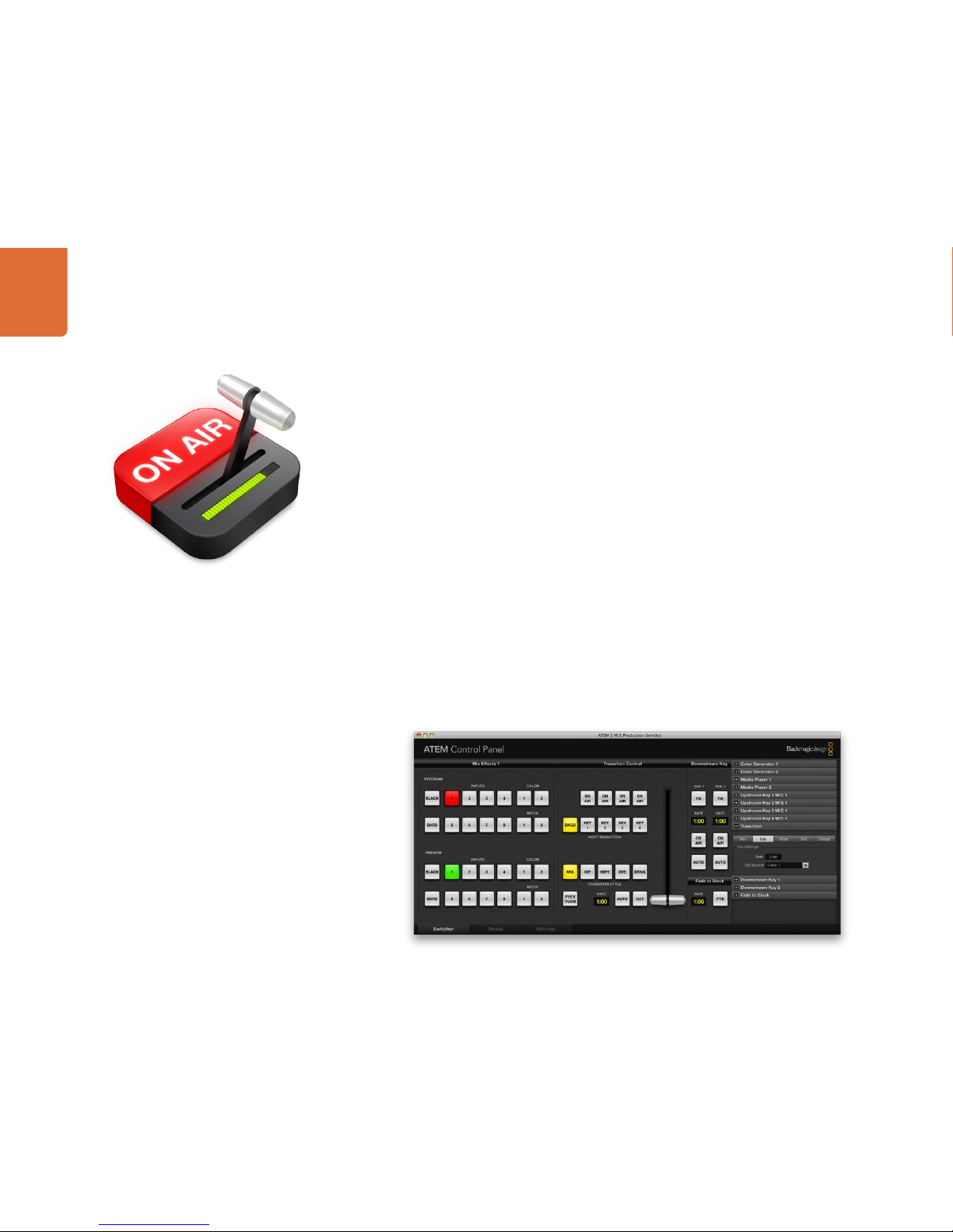
Interface Overview
The ATEM Software Control is included with your ATEM Production Switcher, and allows you to control your
switcher in a similar way to a full hardware control panel. However instead of menu buttons, it uses a range
of pallets on the right side that shows you all processing features of your production switcher, and allows
settings to be easily made.
You can also use the ATEM Software Control to configure your switcher settings as well as upload graphics
and manage the media pool.
Switcher Control Panel
The software control panel user interface has three tabs; Switcher, Media and Settings, which can be
accessed by selecting the tab at the bottom left of the screen. The media and settings tabs contain unique
settings for the switcher, which can only be made from the software control panel.
When first launched, the switcher screen is selected, which is the main control interface for the switcher.
The software control panel must be connected to a switcher chassis to run.
Mouse or Trackpad Operation
The virtual buttons, sliders and fader bar on the Software Control Panel are operated using your computer
mouse or a trackpad if you’re using a laptop.
To activate a button, click once with the left mouse button. To activate a slider, click and hold down the left
mouse button while dragging. To control the fader bar, click and hold down the left mouse button on the
fader bar handle and drag in the desired direction of travel.
Using ATEM Software Control
25
Using Keyboard Hot Keys
Hot keys can be used allowing convenient control of some switcher functions using a standard QWERTY
keyboard as shown in the following table:
Hotkeys Function
<1> - <8> Previews source on switcher Inputs 1 - 8
<Shift> <1> - <8> Hot switches source on switcher Inputs 1 - 8 to Program output
<1> - <8> with <Caps Lock> ON Hot switches source on switcher Inputs 1 - 8 to Program output
<Space> CUT
<Return> or <Enter> AUTO
More information on how to use the switcher control panel is included in the next sections.
Media Manager
The media manager allows you to upload graphics and image sequences to the media pool in the ATEM
switcher. Each ATEM switcher model has memory for graphics that’s called the media pool. This memory
varies in size between different ATEM models, and holds images with alpha channel that can be assigned to
a media player for use in the production. The ATEM Television Studio holds 2 still graphics with alpha and
the ATEM 1 M/E and 2 M/E hold 32 still graphics and 2 clips.
So for example you could have the maximum 32 still graphics and 2 clips loaded that will be used on your
live production and then assign each of the 2 media players to various stills as you work. As you take a
graphic off air, you can change the media player graphic to the next graphic you want, and then you can put
that media player back on air with the new graphic.
When a still or clip is loaded into the media pool, the alpha channel is loaded automatically if one is included
in the image. When a still or clip is loaded into a media player, the output of the media player will include
both key and fill outputs that need to be routed into keyers in the switcher. So if your graphics have an alpha
channel, be sure you select both the fill and key outputs of the media player into the switchers keyers!
Using ATEM Software Control
26
Switcher Settings
The last tab in the ATEM Software Control allows you to change the video input selections and labels.
Setting labels is important, and they are visible in the multi view output as on-screen labels and on the
broadcast control panel in the source names row.
In the settings tab, you can also set the switcher video standard. This is the master video standard that the
whole switcher operates at, and it's very important you set this to the same video standard as your video
inputs. More details on setting the video standards is included later in this manual.
The switcher settings also let you customize your multi view. The multi view can change its orientation and,
on the ATEM 1 M/E and 2 M/E production switchers, any of the 8 video views can be changed allowing you
to view any source in the switcher. This lets you monitor cameras, internal sources, media players and even
aux. outputs on a single monitor. Multi view really saves space when doing portable location based events
because you only need a single monitor.
Using the Software Control Panel
The switcher tab is the main control interface for the switcher. During live production, the switcher tab can
be used to select sources and take them to air.
You can select the transition style, manage upstream/downstream keyers and turn on/off the master fade to
black. The palettes on the right hand side of the interface are where you adjust transition settings including
transition rates, adjust color generators, control media players, and adjust the upstream and downstream
keyers as well as control fade to black rate.
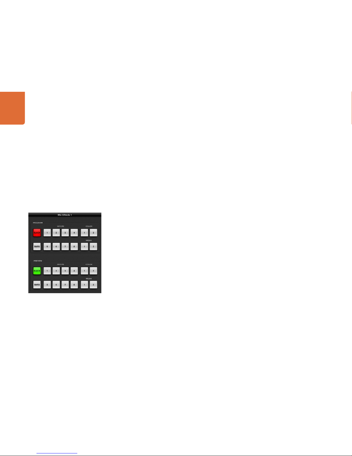
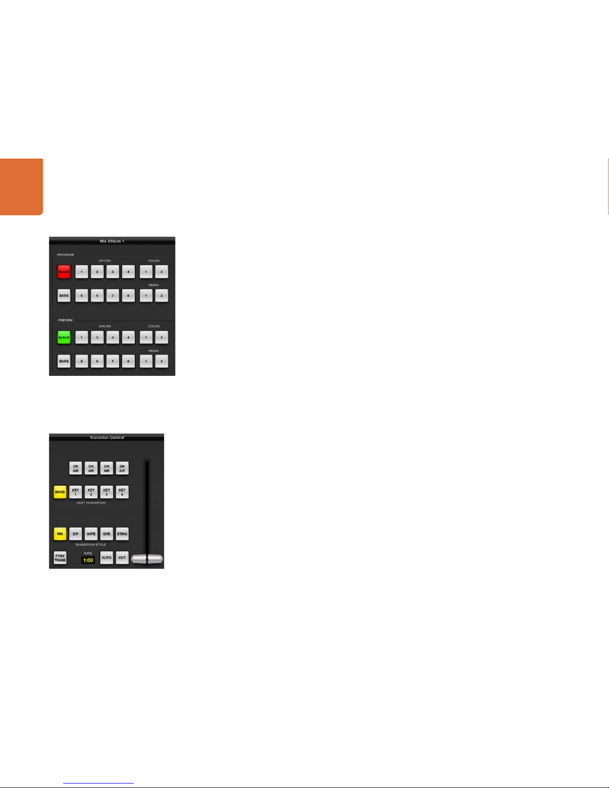
Mix Effects
The mix effects block of the switcher tab contains all the source select buttons for the program and preview
buses, allowing external inputs or internal sources to be selected for next transition previewing or switching
to air. On multiple M/E switcher models, this part of the interface controls M/E 1.
ATEM Mix Effects
Using ATEM Software Control
27
Program Bus Source Select Buttons
The program bus source select buttons are used to hot switch background sources to the program output.
The source currently on air is indicated by a button that is illuminated red.
INPUTS Input buttons match the number of external switcher inputs.
BLACK Color black source internally generated by the switcher.
BARS Color bars source internally generated by the switcher.
COLOR 1 and 2 Color sources internally generated by the switcher.
MEDIA 1 and 2 Internal media players that display stills or clips stored in the switcher.
Preview Bus Source Select Buttons
The preview bus source select buttons are used to select a background source on the preview output, this
source is sent to the program bus when the next transition occurs. The currently selected preview source is
indicated by a button that is illuminated green.
INPUTS Input buttons match the number of external switcher inputs.
BLACK Color black source internally generated by the switcher.
BARS Color bars source internally generated by the switcher.
COLOR 1 and 2 Color sources internally generated by the switcher.
MEDIA 1 and 2 Internal media players that display stills or clips stored in the switcher.
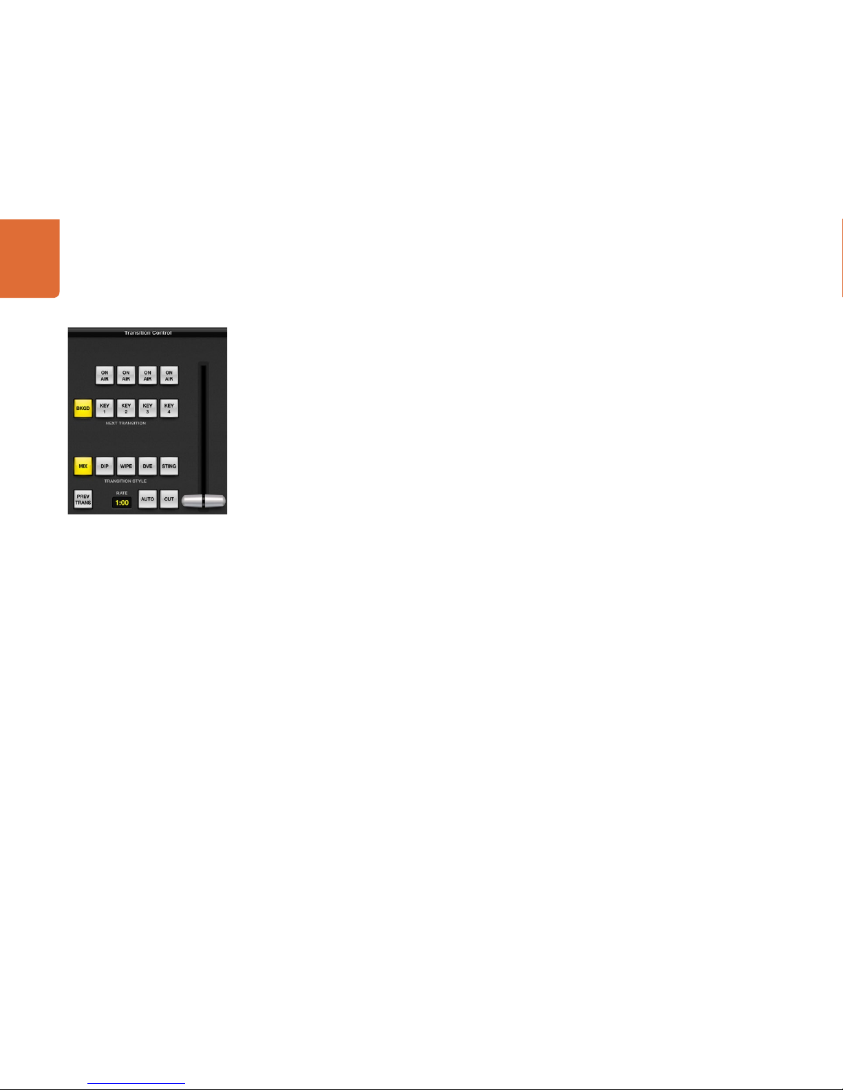
Transition Control and Upstream Keyers
CUT
The CUT button performs an immediate transition of the program and preview outputs, overriding the
selected transition style.
AUTO/RATE
The AUTO button will perform the selected transition at the rate specified in the RATE display. The
transition rate for each transition style is set in the transition palette for that style and is displayed in
the RATE window of the transition control block when the corresponding TRANSITION STYLE button
is selected.
The AUTO button illuminates red for the duration of the transition and the RATE display updates to indicate
the number of frames remaining as the transition progresses. If an ATEM broadcast panel is connected, the
fader bar indicator on the panel updates to provide visual feedback on the progress of the transition.
Transition Control
ATEM Mix Effects
Using ATEM Software Control
28
Fader Bar
The fader bar is used as an alternative to the AUTO button and allows the operator to manually control
the transition with a mouse. The AUTO button illuminates red for the duration of the transition and the
RATE display updates to indicate the number of frames remaining as the transition progresses. If an ATEM
broadcast panel is connected, the fader bar Indicator on the panel updates to provide visual feedback on
the progress of the transition.
Transition Style
The TRANSITION STYLE buttons allow the operator to select one of five types of transitions; mix, dip, wipe,
DVE, and stinger. The available transitions depend on your switcher model. For example the Television
Studio does not have DVE and stinger transitions. The selected transition type is indicated by a yellow
illuminated button.
PREV TRANS
The PREV TRANS button enables the preview transition mode, allowing the operator to verify a mix, dip,
wipe or DVE transition by performing it on the preview output using the fader bar. When the PREV TRANS
is selected you will see the preview output match the program output, and then it's simple to practice your
selected transition with the fader bar to confirm you are going to get what you want. This is a very helpful
feature to avoid mistakes on air!
Next Transition
The BKGD, KEY 1, KEY 2, KEY 3, KEY 4 buttons are used to select the elements which will transition on air or
off air with the next transition. The number of available keyers depends on your switcher model. All keys can
be faded on and off when the main transition occurs, or you can select just keys to transition individually, so
the main transition control can be used to fade keys on and off.
When selecting the elements of the next transition, the switcher operator should look at the preview video
output because it provides an accurate representation of what the program output will look like after the
transition is completed. When only the BKGD button is selected, a transition from the current source on the
program bus to the source selected on the preview bus will occur without any keyers. You can also select
only keyers to transition, leaving the current background live throughout the transition.
ON AIR
The ON AIR indicator buttons indicate which of the keys are currently on air and can also be used to
immediately cut a key on or off air.
Transition Control
Using ATEM Software Control
29
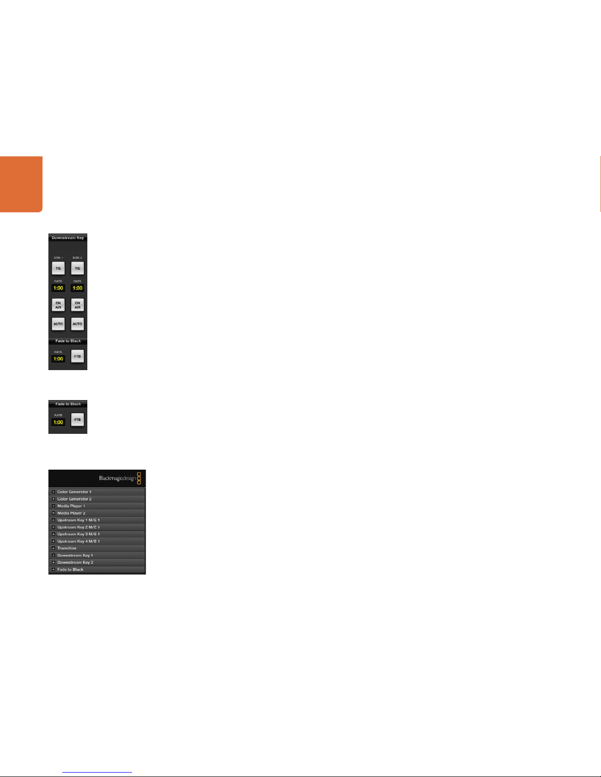
Downstream Keyers
TIE
The TIE button will enable the DSK on the preview output, along with the next transition effects, and tie it to
the main transition control so that the DSK can be taken to air with the next transition.
The DSK will transition at the rate specified in the RATE display of the transition control block. If the DSK is
tied, the signal routing to the clean feed 1 is unaffected.
ON AIR
The ON AIR button is used to cut the DSK on or off air and indicates whether the DSK is currently on or off
air. The button is illuminated if the DSK is currently on air.
AUTO
The AUTO button will mix the DSK on or off air at the rate specified in the DSK RATE window. This is similar
to the main AUTO rate on the transition control block, however it's limited only to the specific downstream
keyer. This can be used to fade up and down bugs and logos, such as live or replay bugs during production,
without interfering with the main program production transitions.
Fade to Black (FTB)
The FTB button will fade the whole program video output to black at the rate specified in the fade to black
RATE window. Once the program output has been faded to black, the FTB button will remain illuminated red
until it is pressed again, fading the program output up from black at the same rate. Fade to black is mostly
used at the start of your production, and at the end of your production, or when cutting to commercial
breaks. It ensures all layers in the switcher are faded down together. A fade to black cannot be previewed.
Processing Palettes
The following processing palettes are available in the software control panel for the ATEM 1 M/E Production
Switcher model. These change based on the model you’re connected to, and are an easy way to see what
processing is available in the switcher. Different ATEM models will have different features, so the palettes
can change. The palettes also show the order of the processing in the switcher.
You can expand and minimize palettes to save space and scroll them up and down to get the adjustments
you need to set.
Color Generator 1 and 2
The ATEM switcher has two color matte generators which can be configured from the color generator
palette using a color picker or by setting hue, saturation, and luminance levels.
Fade to Black
Downstream Key
Processing Palettes
 Loading...