

Page 1

NF520-A2 SE /NF520-A2 Se tu p Ma nua l
FCC Inf or m at ion and Copyright
This equipment has been tes ted and found to comply with the limits of a Class
B digital device, pursuant to Part 15 of the FCC Rules. T hese limits are designed
to provide reasonable protec tion ag ai nst harmful interference in a resi dential
installation. T his equipment generates, uses , and can radiate radio frequency
energy and, if not ins talled and used in accordance with the instructions, may
cause harmful interference to radio communications. There is no guarantee
that i nte rference wil l not occur in a pa r ticula r ins ta llatio n.
The ve ndor makes no re prese n ta tio ns o r warranties wi th respec t t o t h e
contents here and specially disclaims any implied warranties of merchantability
o r fi tnes s fo r a ny p urp os e . Fu rthe r t he ve nd o r res e rves the ri g ht to rev is e t his
publication and to make changes to the c ontents here without obligation to
notify any party beforehand.
D uplic a tion o f this publicatio n, in pa rt o r in wh ol e, is no t allowed wit ho ut first
obtaining the vendor’s approval in writing.
The content of this user’s manual is subject to be c hanged without notice and
we will not be responsible for any mis takes found in this user’s manual. All the
brand and produc t names are trademarks of their respective companies .
Page 2

Table of Contents
Chapter 1: Introduction .............................................1
1.1 Before You Start...................................................................1
1.2 Package Checklist................................................................ 1
1.3 Motherboard Features..........................................................2
1.4 Rea r Pa nel Co n necto rs (for Ve r 6.x) ....................................... 4
1.5 Rear Pa nel Co n necto rs (for Ve r 5 .x).......................................4
1.6 Mo t he r boa rd Layou t (NF520-A2 SE )......................................5
1.7 Mot he r boa r d La yo u t (NF520-A2).......................................... 6
Chapter 2: Hardware Installation ..............................7
2.1 Installing Ce ntral Proce ssing Unit (CPU) ................................ 7
2.2 FAN He ade rs........................................................................9
2.3 Installing Sy stem Memory.....................................................10
2.4 Con nectors a nd Slo ts............................................................12
Chapter 3: Headers & Jumpers Setup......................14
3.1 How to Se t u p Ju mper s..........................................................14
3.2 Det ail Settin gs.....................................................................14
Chapter 4: RAID Functions.......................................21
4.1 Operation Syste m................................................................21
4.2 Raid Arrays.........................................................................21
4.3 How RA I D Wor k s.................................................................21
Chapter 5: Useful Help ..............................................24
5.1 Driver Instal latio n Note.......................................................24
5.2 Award B IOS Beep Code ........................................................25
5.3 Extra Informati on ................................................................25
5.4 Troubleshooting...................................................................26
Chapter 6: WarpSpeeder™ III .................................27
6.1 Introduction........................................................................27
6.2 System Requirement............................................................27
6.3 Installation.........................................................................28
6.4 WarpSpeeder™ III................................................................29
Appendencies: SPEC In Other Language ................34
German................................................................................................34
France..................................................................................................36
Italian..................................................................................................38
Spanish................................................................................................40
Portuguese ...........................................................................................42
Polish...................................................................................................44
Russian................................................................................................46
Arabic..................................................................................................48
Japanese..............................................................................................50
Page 3

NF520-A2 SE/NF520-A2
CHAPTER 1: INTRODUCTION
1.1 BEFORE YOU START
Tha nk you for choosing ou r product. Be fo re you start ins talling the
mo therboa rd , plea se make sure you fo llo w the ins tru ctio ns be lo w:
Prepare a dry and stable working environment with
s uf ficie nt ligh ting .
Always disconnect the computer from power outlet
be fo re ope ration.
Befo re yo u take the m o the rboa rd o u t from a n ti -s ta t ic
bag, ground yourself properly by touching any safely
grounded applian ce, o r use grounded wris t s trap to
remove the static charge.
Avo id tou ch ing the com pone nts o n mo the rboa rd or the
rea r side of the boa rd un les s necessa ry. Ho ld the boa rd
on the edge , do not try to be nd or flex the boa rd.
Do no t lea ve any unfas tened sma ll pa rts inside the
case after installation. Loose parts will cause short
circuits which ma y damage the equ ipment.
Keep the computer from dangerous area, such as heat
sou rce , humid air and water.
1.2 PACKAGE CHECKLIST
HDD Cable X 1
Se ria l ATA Cab le X 1
Rear I/O Panel for ATX Case X 1
Use r’s Ma nua l X 1
Fully Setup Driver CD X 1
FDD Cable X 1 (optional)
USB 2.0 Cable X1 (optional)
S/P DI F ou t C a ble X 1 (op tiona l)
Se ria l ATA Po we r Cab le X 1 (o pt io nal)
Note: The package contents may differ by area or your motherboard version.
1
Page 4
Motherboard Manual
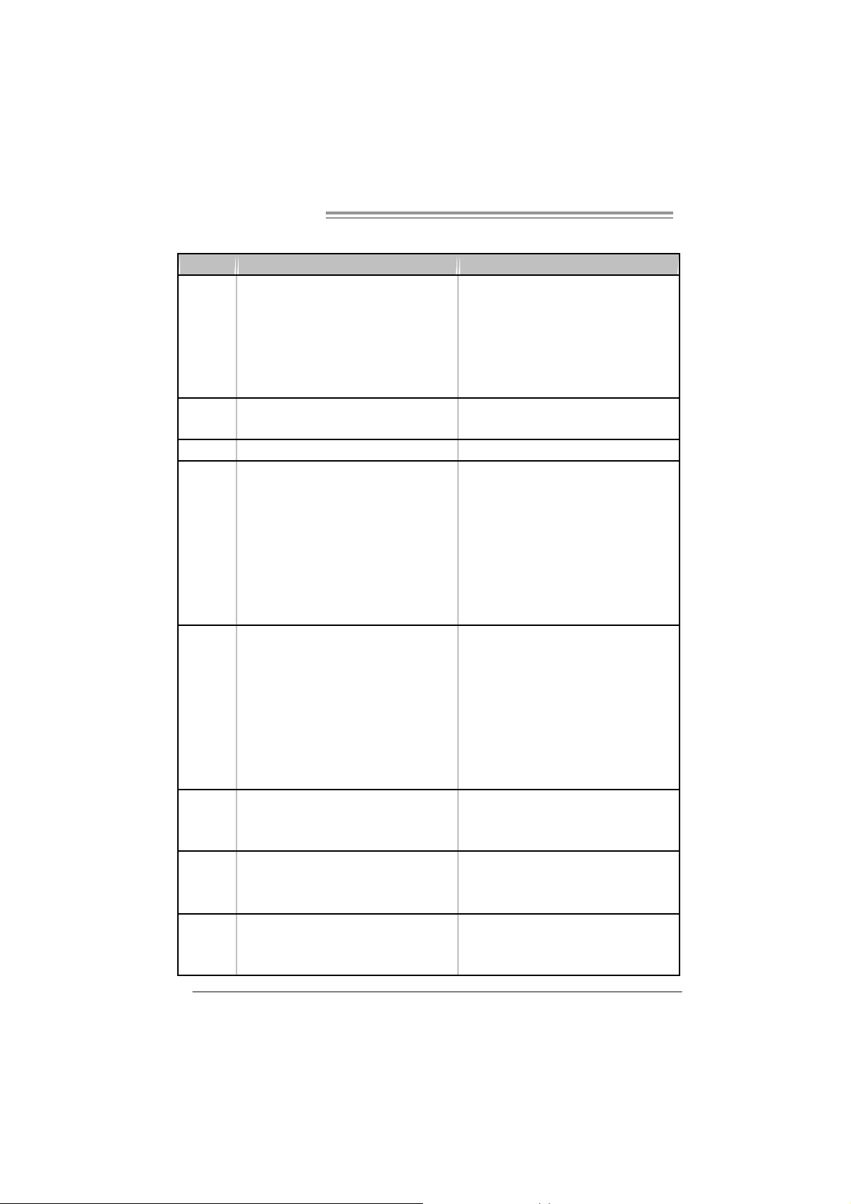
1.3 MOTHERBOARD FEATURES
NF520-A2 SE NF520-A2
Socket AM2
AM D Athlon 64 / At hl on 64 FX / Althl on 64 X 2 /
CPU
FSB
Chi pset nForce 520 nForce 520LE
Super I/O
Main
Memory
IDE
SA TA
LAN
Sempron process ors
AM D 64 Architec t ure enables 32 and 64 bit
computing
Supports Hyper Trans port and Cool=n=Quiet
Support HyperTransport
Supports up to 1GHz B andwidt h
ITE 8716F
Provides the mos t commonly used legacy Super
I/O functionality.
Low Pin Count Interfac e
Environment Control initiatives,
H/W Monitor
Fan Speed Controller
ITE's "Smart Guardian" function
DDR2 DIMM Slot x 4
Eac h DIMM s upports 256/512/1024/2048 MB
DDR2
Max Memory Capicity 8G
Dual Channel Mode DDR2 memory module
Supports DDR2 533/667/800
Registered DIMM and ECC DIMM is not
supported
Integrated IDE Controller
Ultra DMA 33 / 66 / 100 / 133 Bus M ast er Mode
supports PIO Mode 0~ 4,
Integrated Serial ATA Controller
Data transfer rates up to 3.0 Gb/s.
SATA Version 2.0 specificat ion compliant.
Realtek RTL8201CL PHY
10/100 Mb/s auto negotiat i on
Half / Full duplex capability
2
Socket AM2
AM D Athlon 64 / At hl on 64 FX / Althl on 64 X 2 /
Sempron process ors
AM D 64 Architec t ure enables 32 and 64 bit
computing
Supports Hyper Trans port and Cool=n=Quiet
Support HyperTransport
Supports up to 1GHz B andwidt h
ITE 8716F
Provides the mos t commonly used legacy Super
I/O functionality.
Low Pin Count Interfac e
Environment Control initiatives,
H/W Monitor
Fan Speed Controller
ITE's "Smart Guardian" function
DDR2 DIMM Slot x 4
Eac h DIMM s upports 256/512/1024/2048 MB
DDR2
Max Memory Capicity 8G
Dual Channel Mode DDR2 memory module
Supports DDR2 533/667/800
Registered DIMM and ECC DIMM is not
supported
Integrated IDE Controller
Ultra DMA 33 / 66 / 100 / 133 Bus M ast er Mode
supports PIO Mode 0~ 4,
Integrated Serial ATA Controller
Data transfer rates up to 3.0 Gb/s.
SATA Version 2.0 specificat ion compliant.
Realtek RTL8201CL PHY
10/100 Mb/s auto negotiat i on
Half / Full duplex capability
Page 5
NF520-A2 SE/NF520-A2
NF520-A2 SE NF520-A2
Realtek ALC861V D (Ver 6.x)
Realtek ALC888 (Ver 5.x)
Sound
slots
On Board
Connec t or
Back Panel
I/O
Board S ize 200 mm (W) x 293 mm (L) 200 mm (W) x 293 mm (L)
Special
Feature
OS S upport
5.1 channels audio out (V er 6.x)
7.1 channels audio out (V er 5.x)
Supports HD Audio
PCI s lot x3 PCI s lot x3
PCI Express x16 slot x1 PCI Expr ess x16 slot x1
PCI Express x 1 slot x2 PCI Express x 1 slot x2
Fl oppy c onnector x1 Fl oppy c onnect or x 1
Printer Port connec tor x1 Printer Port connec tor x1
IDE C onnector x1 I DE Connect or x1
SA TA Con nect or x4 SA TA C onnect or x2
Front Panel Connector x1 F ront Panel Connect or x1
Front Audio Connector x1 Front Audio C onnector x1
CD- in C onnec tor x1 C D-i n Connector x1
S/PDIF out connector x1 S/PDIF out connector x1
CP U Fa n header x1 C PU F an header x 1
Sys tem F an header x1 S ystem Fan hea der x1
USB connector x3 USB c onnector x2
Chassis open header (optional) x1 Chassis open header (optional) x1
CMOS clear header x1 CMOS clear header x1
Power Connector (24pin) x1 Power Connector (24pin) x1
Power Connector (4pin) x1 Power Connector (4pin) x1
PS/2 Keyboard x1
PS/2 Mouse x1
S e ri a l P ort x 1
LAN port x1
USB Port x4
Audio Jack (Ver 6.x) x3
Audio Jack (Ver 5.x) x6
RAID 0 / 1 / 0+ 1 support R AID 0 / 1 support
Wi ndows 2000 / XP / VISTA
Biostar Reserves the right to add or remove
support for any OS with or without notice.
Realtek ALC861V D (Ver 6.x)
Realtek ALC888 (Ver 5.x)
5.1 channels audio out (V er 6.x)
7.1 channels audio out (V er 5.x)
Supports HD Audio
PS/2 Keyboard x1
PS/2 Mouse x1
S e ri a l P ort x 1
LAN port x1
USB Port x4
Audio Jack (Ver 6.x) x3
Audio Jack (Ver 5.x) x6
Wi ndows 2000 / XP / VISTA
Biostar Reserves the right to add or remove
support for any OS with or without notice.
3
Page 6
Motherboard Manual
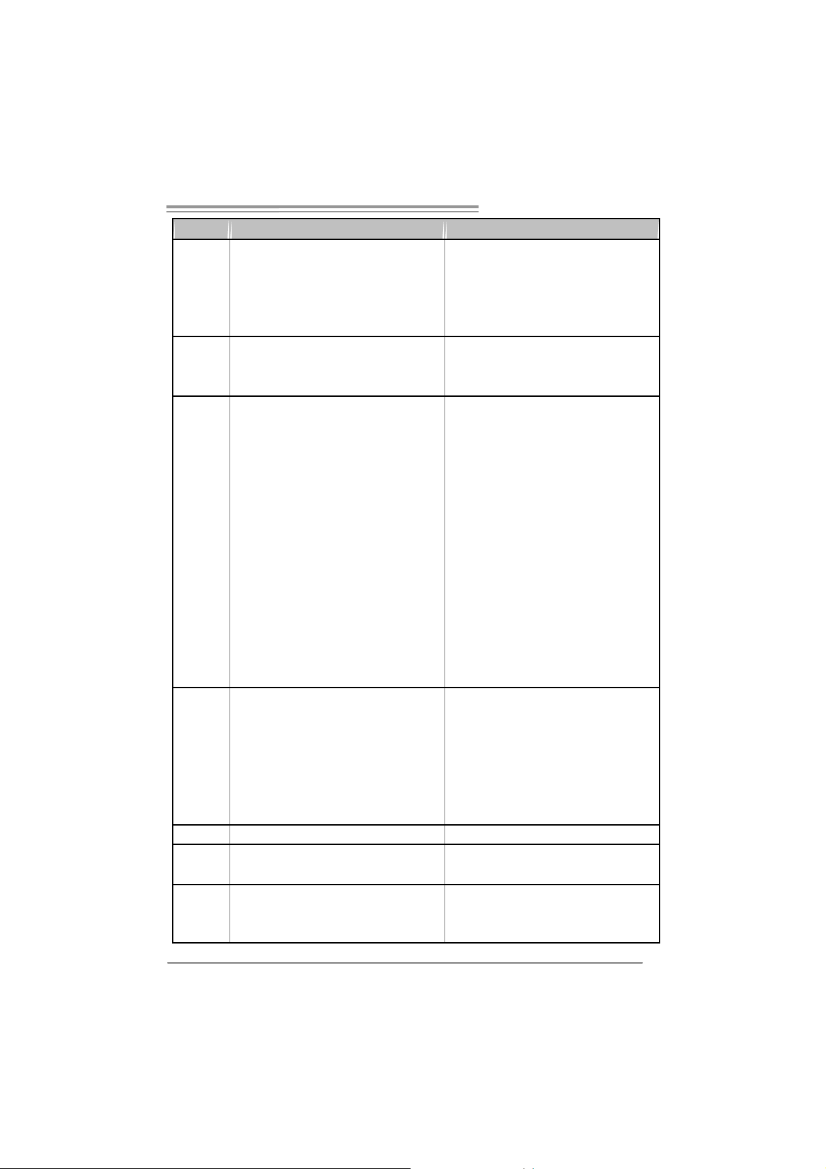
1.4 REAR PANEL CONNECTORS (FOR VER 6.X)
PS /2
Mouse
PS/ 2
Keyboard
COM1 USBX2USBX2
LAN
1.5 REAR PANEL CONNECTORS (FOR VER 5.X)
L ine In/
Surround
Lin e Out
Mic In 1/
B a ss/ C e nter
PS/2
Mouse
PS/ 2
Keyboard
COM1 USBX2USBX2
Center
Rear
Side
Line In
Line Out
Mic In
LAN
4
Page 7
NF520-A2 SE/NF520-A2
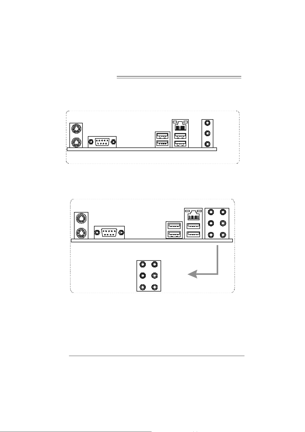
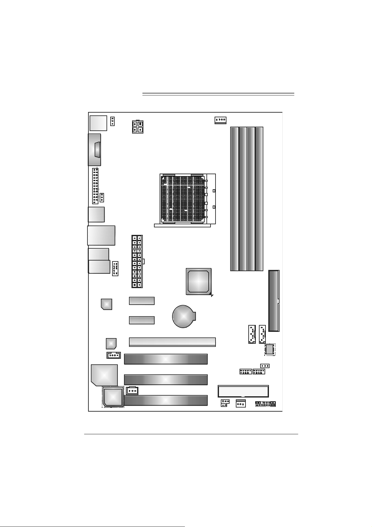
1.6 MOTHERBOARD LAYOUT (NF520-A2 SE)
JKBMS1
JCOM1
JPRNT 1
JUSB1
JUSBLAN1
JAUDIO2
(for Ver 5.x )
JAUD IO1
(for Ver 6.x)
LAN
JKBPWR1
JUSBPWR 1
JAUD IOF1
JATXPWR 2
JATXPWR 1
PEX1_1
nForce
520
Socket A M2
JCFAN1
DIMMA1
DIMMB1
SATA3 SATA4
DIMMB2
DIMMA2
IDE1
Cod ec
J CDIN1
Super I/O
Note: represents the 1■
PEX1_2
JSPDIF_ OUT1
PCI1
PCI 2
PCI3
PEX16_1
st
BAT1
pin.
JCMOS1
JCI1 (o ptional )
SATA1 SATA2
JUSBPWR2
JUSB2 JUSB3 JUSB4
FDD1
JSFAN1 JPANEL1
BI O S
5
Page 8
Motherboard Manual
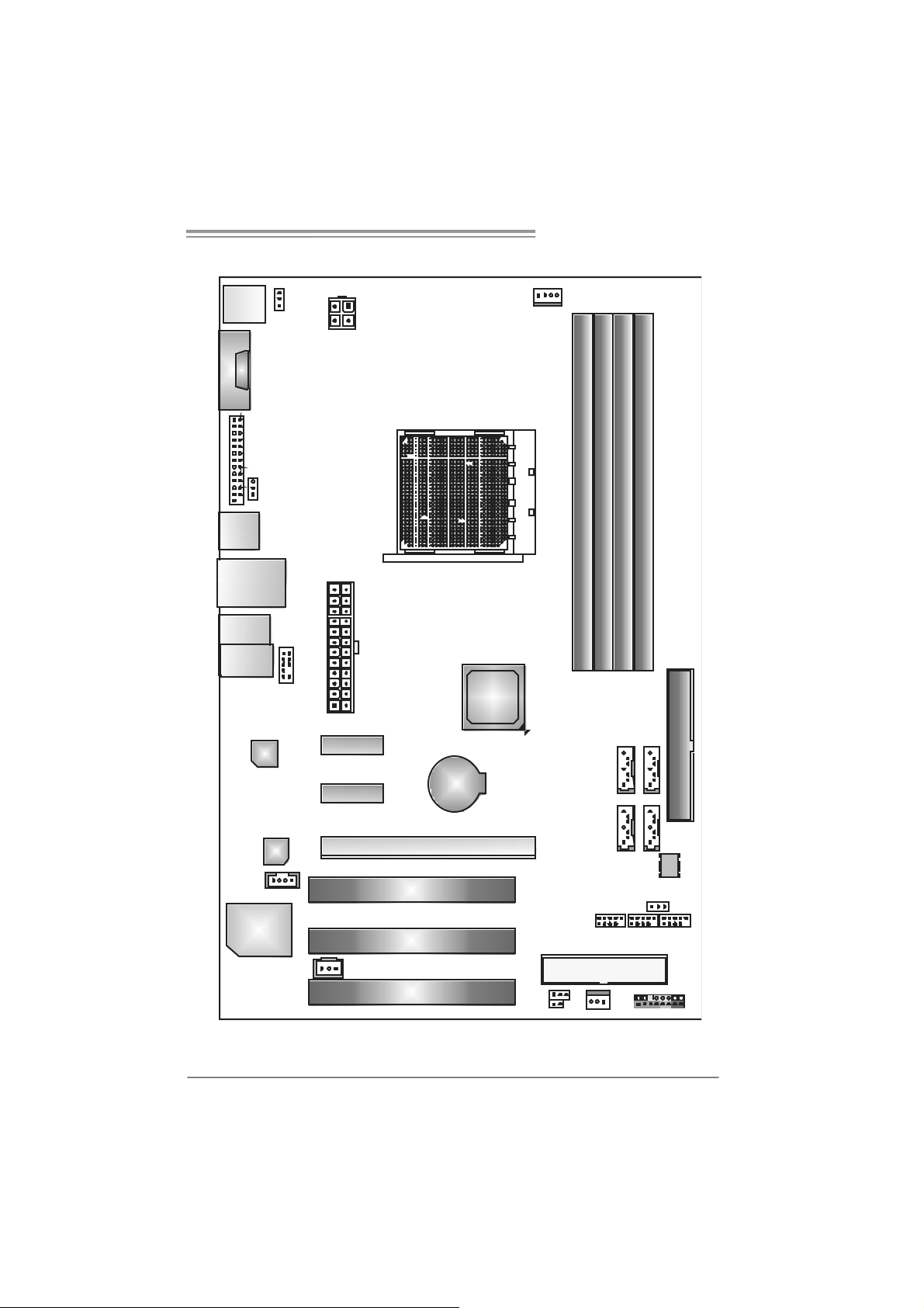
1.7 MOTHERBOARD LAYOUT (NF520-A2)
JKBMS1
JCOM1
JPRNT 1
JUSB1
JUSBLAN1
JAUDIO2
(for Ver 5.x )
JAUD IO1
(for Ver 6.x)
LAN
JKBPWR1
(O ptio nal)
JUSBPWR1
(O ptio nal)
JAUD IOF1
JATXPWR2
JATXPWR1
PEX1_1
nForce
520LE
Socket A M2
JCFAN1
DIMMA1
DIMMB1
DIMMB2
DIMMA2
IDE1
6
Cod ec
J CDIN1
Super I/O
BIOS
(For Ver 6. 0)
Note: represents the 1■
PEX1_2
JSPDIF_ OUT1
PCI1
PCI 2
PCI3
PEX16_1
st
BAT1
pin.
JUSBPWR 2(Optio nal)
JCMOS1
JCI1 (o ptional )
SATA1 SATA2
(F or Ver 6. 1 or a bove)
JUSB2 JUSB3
FDD1
JSFAN1 JPANEL1
BI O S
Page 9
NF520-A2 SE/NF520-A2
CHAPTER 2: HARDWARE I NSTALLATION
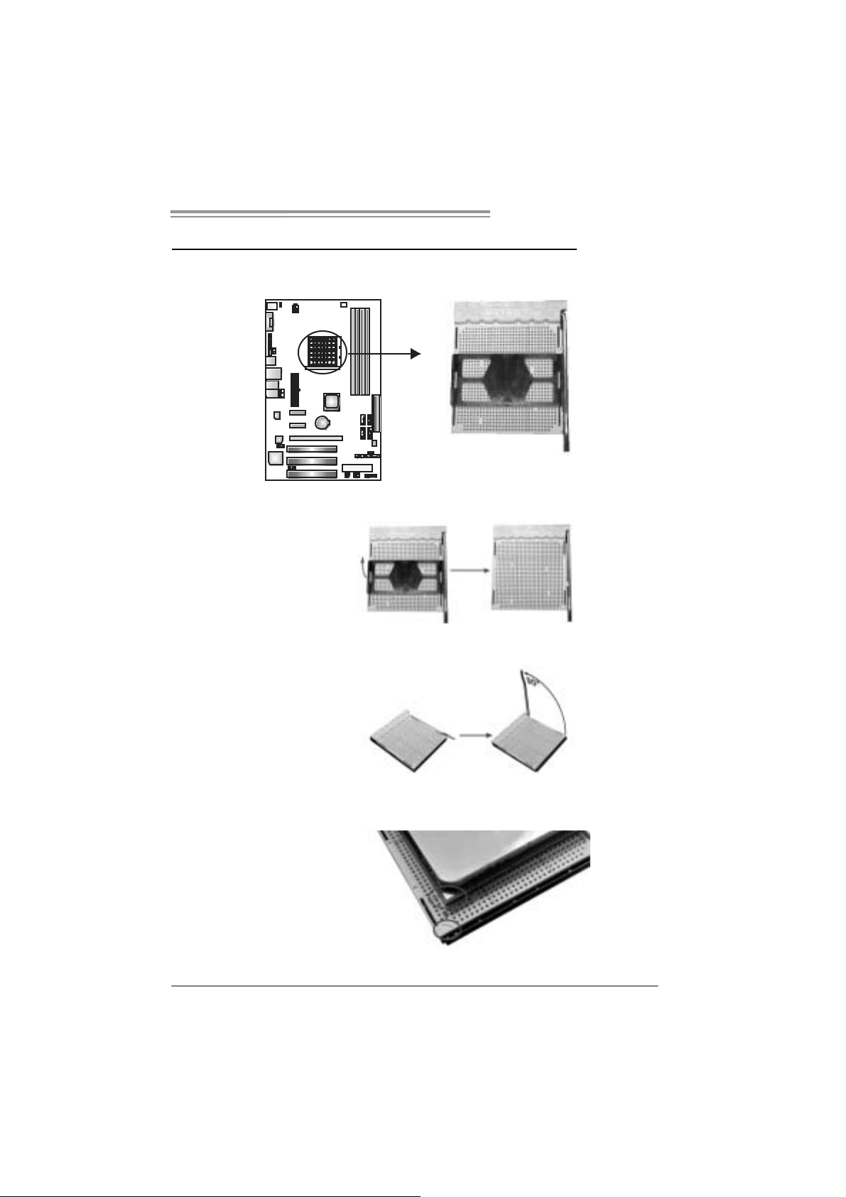
2.1 INSTALLING CEN TRAL PROCESSING UNIT (CPU)
Step 1: Remove the socket protection cap.
Step 2: Pull the lever toward direction A from the socket and then raise the
lever up to a 90-degree angle.
Step 3: Look for the white triangle on socket, and the gold triangle on
CPU should point forwards this white triangle. The CPU will fit
only in the correct orientation.
7
Page 10

Motherboard Manual
Step 4: Hold the CPU down firmly, and then close the lever toward direct
B to complete the installation.
Step 5: Put the CPU Fa n on the CPU a nd buckle it. Connect the CPU
FAN power cable to the JCFAN1. This completes the installation.
8
Page 11
NF520-A2 SE/NF520-A2
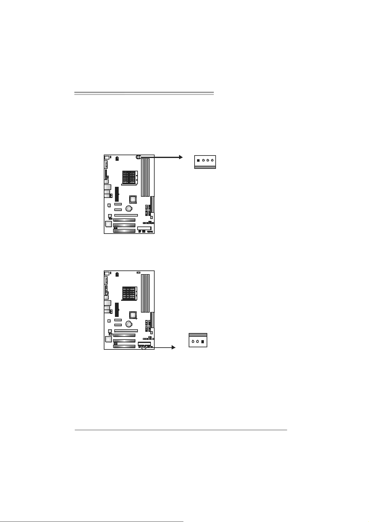
2.2 FAN HEADERS
These fan headers support cooling-fans built in the computer. The fan
cable and connector may be different according to the fan manufacturer.
Connect the fan cable to the connector while matching the black wire to
pin#1.
JCFAN1: CPU Fan Header
14
JSFAN 1: Syst e m F a n H ea der
Pin
Pin
Assignment
1 Ground
2 +12V
3 FAN RPM
rate sense
4
Smart Fan
Control
Assignment
1 Ground
2 +12V
3 FAN RPM rate
sense
13
Note:
The J CFAN1 su ppor ts 4- pi n he ad c on nec tor , an d JSFAN1s up por ts 3- pi n head c onnect or.
When co nnec ti ng wi t h wires o nto c on nect or s, pl e ase not e that t he re d wi r e i s th e p ositive
and should be c onnec ted to pi n #2, and t he blac k wire is Gr ound an d s h oul d be
conn ecte d t o GND .
9
Page 12
Motherboard Manual
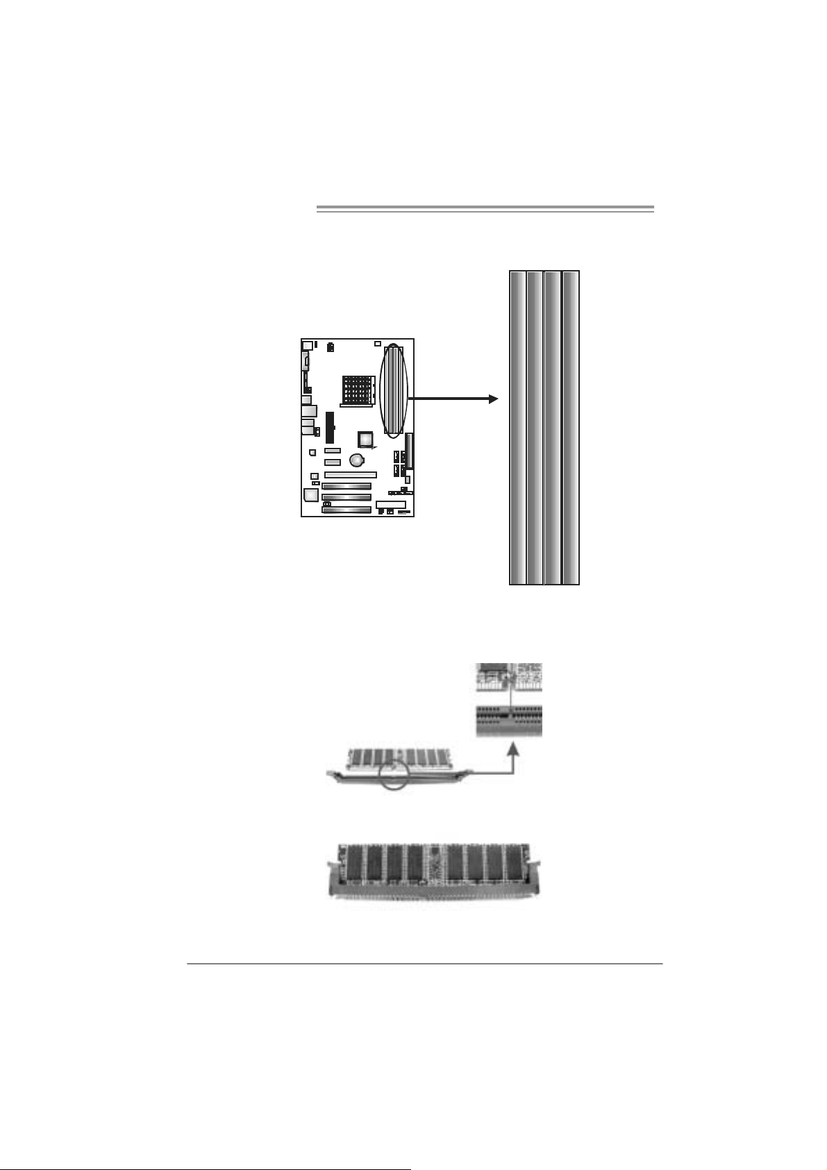
2.3 INSTALLING SYSTEM MEMORY
A. Me mo ry Modu le s
DI MMA 1
DI MMB 1
DI MMA 2
1. Unlock a DIMM slot by pressing the retaining clips outward. Align a
DIMM on the slot such that the notch on the DIMM matches the
break on the Slot.
DI MMB 2
2. Insert the DIMM vertically and firmly into the slot until the retaining
chip snap back in place and the DIMM is properly seated.
10
Page 13

NF520-A2 SE/NF520-A2
B. Memory Capacity
DI MM Socket
Location
DIMMA1 256MB/512MB/1024MB/2048MB
DIMMB1 256MB/512MB/1024MB/2048MB
DIMMA2 256MB/512MB/1024MB/2048MB
DIMMB2 256MB/512MB/1024MB/2048MB
DDR2 Module
To t a l M e m o r y
Size
Max is 8 GB.
C. Dual Channel Memory installation
To trigger the Dual Channel function of the motherboard, the memory
module must meet the following requirements:
Install memory module of the same density in pairs, shown in the
following table.
Du al Channel Statu s
Enabled O O X X
Enabled X X O O
Enabled O O O O
(O means memory installed, X means memory not installed.)
The DRAM bus width of the memory module must be the same (x8 or
x16)
DIMMA1
DIMMB1 DIMMA2 DIMMB2
11
Page 14
Motherboard Manual
2.4 CONNECTORS AND SLOTS
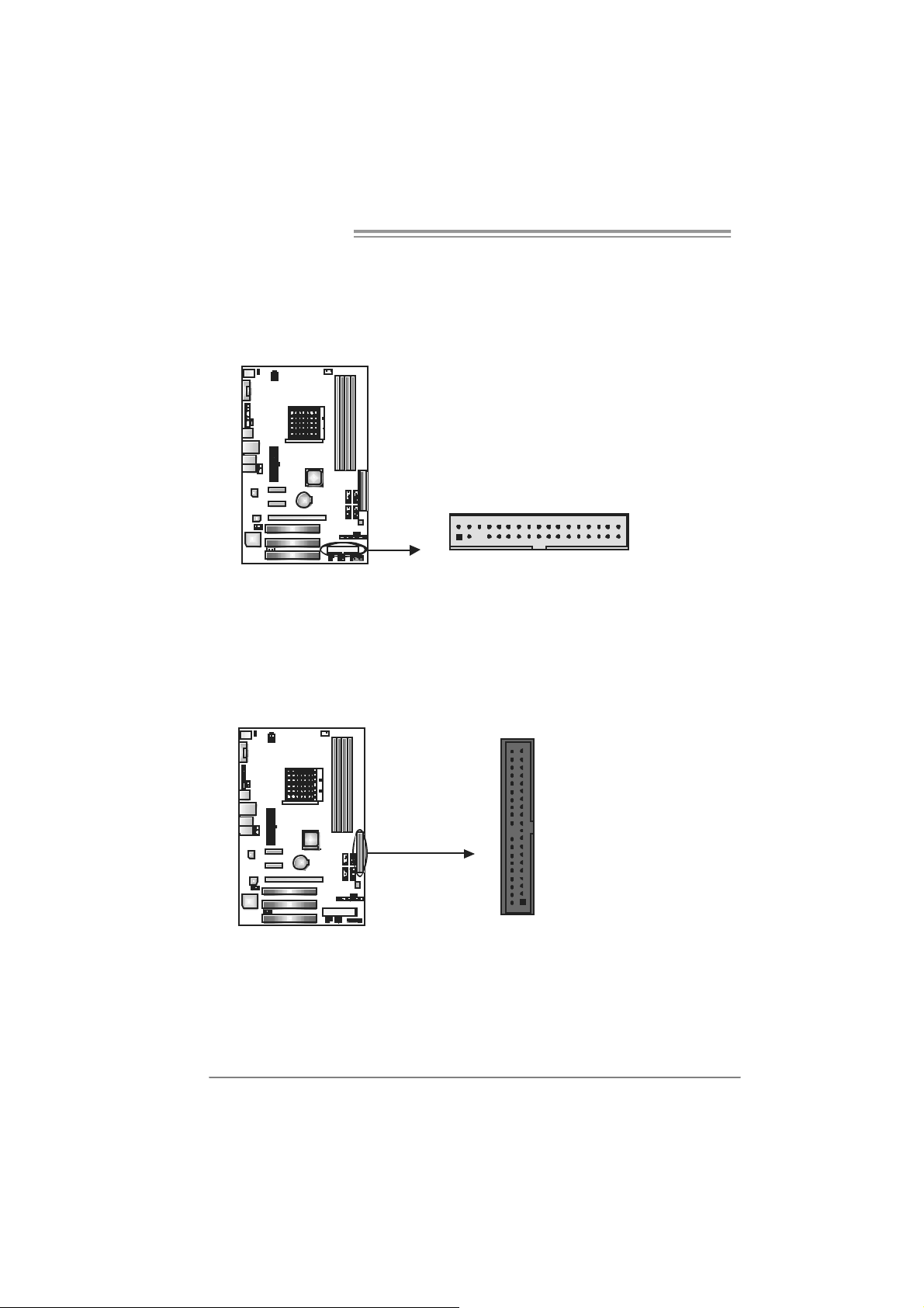
FDD1: Flo ppy Disk Connector
The motherboard prov ides a standard floppy disk connector that supports 360K,
720K, 1.2M, 1.44M and 2.88M floppy disk ty pes. This connector supports the
prov ided f loppy drive ribbon cable.
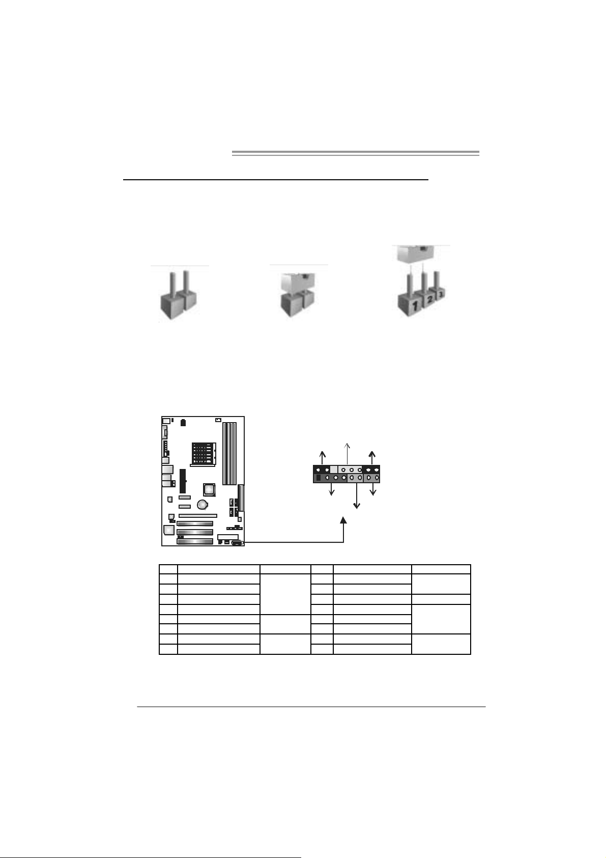
IDE1: H ar d Disk C onnec tor
The motherboard has a 32-bit Enhanced PCI IDE Controller that prov ides PIO
Mode 0~4, Bus Master, and Ultra DMA 33/66/100/133 f unctionality.
The IDE connector can connect a master and a slave drive, so you can connect
up to two hard disk driv es.
2
1
21
34
33
3940
12
Page 15

NF520-A2 SE/NF520-A2
PEX16_1: PCI-Express x16 Slot
- PCI-Ex press 1.0a compliant.
- Maximum theoretical realized bandwidth of 4GB/s simultaneously per
direction, f or an aggregate of 8GB/s totally.
PEX1_1/ PEX1_2: PC I-Express x1 Slots
- PCI-Ex press 1.0a compliant.
- Data transf er bandwidth up to 250MB/s per direct ion; 500MB/s in total.
- PCI-Ex press supports a raw bit-rate of 2.5Gb/s on the data pins.
- 2X bandwidth ov er the tradit ional PCI architecture.
PEX1_1
PEX1_2
PEX16_1
PCI1/PCI2/PCI3: Peri pheral Component Interconne ct Slots
This motherboard is equipped with 3 standard PCI slots. PCI stands f or
Peripheral Component Interconnect, and it is a bus standard for expansion
cards. This PCI slot is designated as 32 bits.
PCI1
PCI2
PCI3
13
Page 16
Motherboard Manual
CHAPTER 3: HEADERS & JUMPERS SETUP
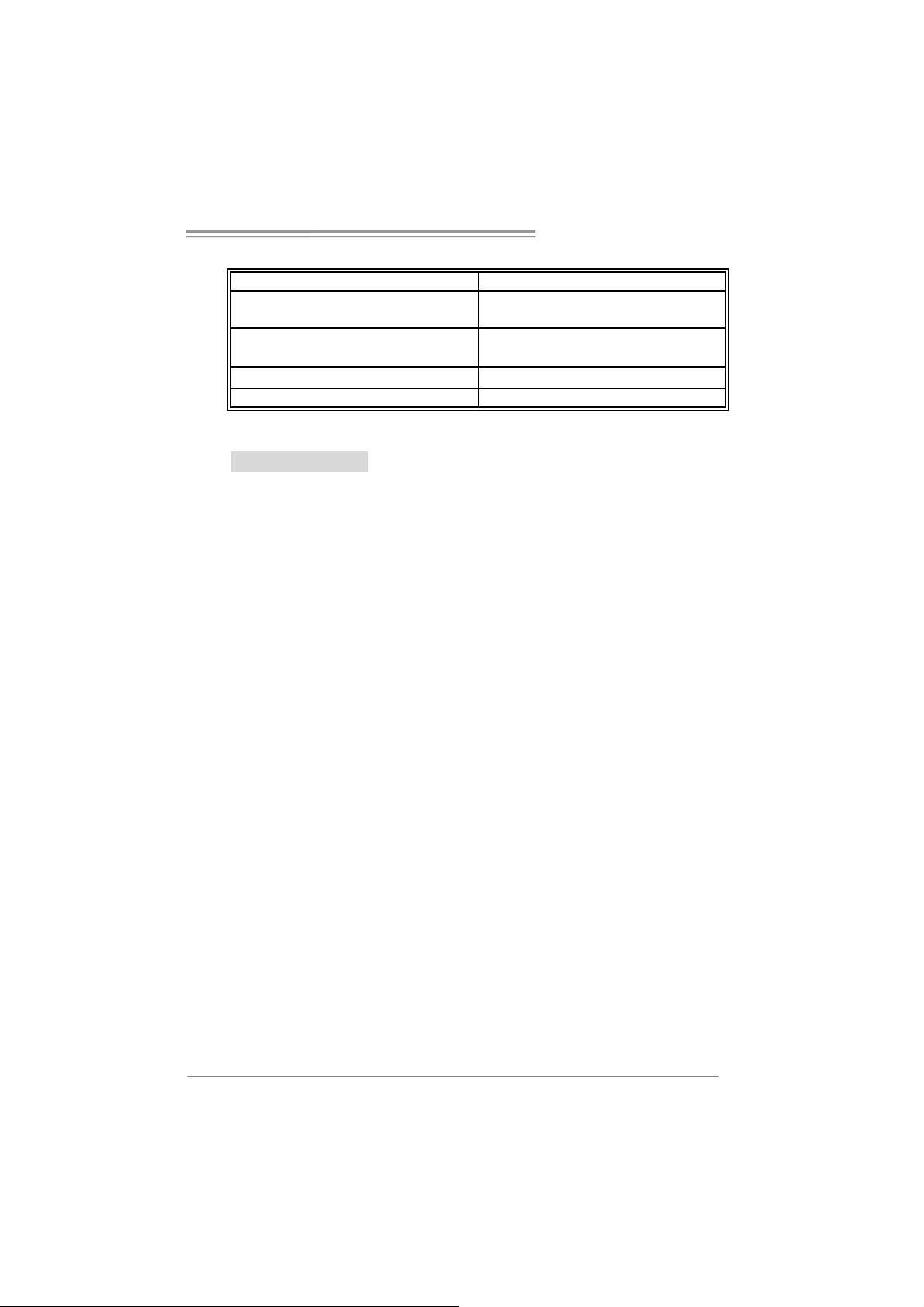
3.1 HOW TO SETUP JUMPERS
The illustration shows how to set up jumpers. When the jumper cap is
placed on pins, the jumper is “close”, if not, that means the jumper is
“open”.
Pin opened Pin closed Pin1-2 closed
3.2 DETAIL SETT INGS
JPANEL1: Front Panel Header
This 16-pin connector includes Power-on, Reset, HDD LED, Power LED, Sleep
button, speaker Connection. It allows user to connect the PC case’s front panel
switch functions.
PWR_L ED
SLP
9
1
SPK
++
HL E D
+
On/ Off
-
-
RST
16
8
14
Pin Assignment Functio n Pin Assignment Function
1 +5V 9 Sleep control
2 N/A 10 Ground
3 N/A 11 N/A N/A
4 Speaker
5 HDD LED (+) 13 Power LED (+)
6 HDD LED (-)
7 Ground 15 Power button
8 Reset control
Speaker
Connector
Hard drive
LED
Reset button
12 Po we r LED (+)
14 Po we r LED (-)
16 Ground
Sleep button
Power LED
Power-on button
Page 17

NF520-A2 SE/NF520-A2
ATX Power Sourc e Conn ector: JAT XPWR1
JATXPWR1 allows user to connect 24-pin power connector on the ATX power
supply.
12
1
Pin Assignment Pin Assignment
24
13
1 +3.3V 13 + 3.3V
2 +3.3V 14 - 12V
3 Gr oun d 15 Gr ound
4 +5V 16 PS_ON
5 Gr oun d 17 Gr ound
6 +5V 18 Groun d
7 Gr oun d 19 Gr ound
8 PW_ OK 20 N C
9 Stand b y Volt ag e+5V 21 + 5V
10 +12V 22 +5V
11 + 12V 23 +5V
12 +3.3V 24 Groun d
JATXPWR2: ATX Powe r Source C onne ctor
By connecting this connector, it will provide +12V to CPU power c ircuit.
2
1
43
Pin
Assignment
1 +12V
2 +12V
3 Ground
4 Ground
15
Page 18

Motherboard Manual
JUS B 2/ JUSB3/JU SB 4: H eader s for U SB 2. 0 P or t s at F ro nt Pa n el
(JU SB4 i s only for NF 5 20 -A 2 SE )
This header allows user to connect additional USB cable on the PC f ront panel,
and also can be connected with internal USB devices, like USB card reader.
JUSB2 JUSB3 JUSB4
(JUSB4 is only f or NF520-A2 SE )
2
10
1
9
SATA1/S ATA2/S ATA3/S ATA4: Serial ATA Connectors
(SATA3 an d SATA4 are only for NF520-A2 S E)
The motherboard has a PCI to SATA Controller with 2 channels SATA interf ace,
it satisfies the SATA 2.0 spec and with transfer rate of 3.0Gb/s.
Pin
SATA3 SATA4
(Onl y fo r NF5 20-A 2 S E)
7
4
1
1 Ground
2 TX +
3 TX -
4 Ground
5 RX6 RX+
7 Ground
Assignment
Pin
1 +5V (fus ed)
2 +5V (fus ed)
3 USB4 USB5 USB+
6 USB+
7 Ground
8 Ground
9 Key
10 NC
Assignment
16
SATA1 SATA2
Page 19

NF520-A2 SE/NF520-A2
JAUDIOF1: Fron t Panel Audio Header
This header allows user to connect the front audio out put cable with the PC f ront
panel. It will disable the output on back panel audio connectors.
Pin
Assignment
1 Mic Left in
2 Ground
3 Mic Right in
12
910
4 GPIO
5 Right line in
6 Jack Sense
7 Front Sense
8 Key
9 Left li ne in
10 Jack Sens e
JCDIN1: CD-ROM Aud io-in Connector
This connector allows user to connect the audio source f rom the v ariaty dev ices,
like CD-ROM, DVD-ROM, PCI sound card, PCI TV turner card etc.
Assignment
Pin
1 Left Channel
Input
2 Ground
3 Ground
4 Right Channel
14
Input
17
Page 20

Motherboard Manual
JSPDIF_O UT1 : Di gital Audio-out Con nec tor
This connector allows user to connect the PCI bracket SPDIF output header.
Pin
1 +5V
2 SPDIF_OUT
3 Ground
13
JU SBPWR1/JUSBP W R2: P owe r S ou rce H eaders f or US B P orts
(Opti onal for N F520 -A2)
Pin 1- 2 Clo se:
JUSBPWR1: +5V for USB ports at JUSB1/JUSBLAN1.
JUSBPWR2: +5V for USB ports at front panel (JUSB2/JUSB3/JUSB4).
Pin 2- 3 Clo se:
JUSBPWR1: USB ports at JUSB1/JUSBLAN1 are powered by +5V standby
JUSBPWR2: USB ports at front panel (JUSB2/JUSB3/JUSB4) are powered
v oltage.
by +5V standby voltage.
Assignment
18
3
1
JUSBPWR1
13
JUSBPWR2
Pin 1-2 close
1
Pin 2-3 close
3
31
1
3
3
1
Note:
In or d er to suppor t this f unc tion “ Po wer - On s ys te m via U SB de vic e,” “ J USB PWR 1/
JUSBPWR 2” jum per c ap s houl d b e place d o n Pi n 2-3 i ndi viduall y.
Page 21

NF520-A2 SE/NF520-A2
JKBPWR1: Power Sou rce Header for PS/2 Keyboard and Mo use
(Opti onal for N F520 -A2)
3
1
31
Pin 1-2 Clos e
+5V for PS/2 keyboard and
mouse.
31
Pin 2-3 close
PS/2 keyboard and mouse are
powered by +5V standby
voltage.
Note:
In or d er to suppor t this f unc tion “ Po wer - on syste m via ke yboar d and mo use”, “ JK BP WR1”
jumper ca p should be pl ac ed on Pi n 2-3.
JCMOS 1 : Clear CMOS H eader
By placing the jumper on pin2-3, it allows user to restore the BIOS saf e sett ing
and the CMOS data, please carefully f ollow the procedures to avoid damaging
the motherboard.
13
Pin 1-2 Close:
Normal Operation (default).
13
13
Pin 2-3 Close:
Clear CMOS data.
※ Clear CMOS Procedures:
1. Remov e AC power line.
2. Set the jumper to “Pin 2-3 close”.
3. Wait f or f ive seconds.
4. Set the jumper to “Pin 1-2 close”.
5. Power on the AC.
6. Reset y our desired password or clear the CMOS dat a.
19
Page 22

Motherboard Manual
JCI1: Chassis Open Header (Optional)
This connector allows system to monitor PC case open status. If the signal has
been triggered, it will record to the CMOS and show t he message on next
boot-up.
JPRNT1: Printer Port Connector
This header allows you to connector printer on the PC.
12
12
Pin
Assignment
1 Case open signal
2 Ground
20
25
Pin Assignment Pin Assignment
1 -Strobe 14 Ground
2 -ALF 15 D ata 6
3 Data 0 16 Ground
4 -Error 17 Data 7
5 Data 1 18 Ground
6 -Init 19 -AC K
7 Data 2 20 Ground
8 -Scltin 21 Busy
9 Data 3 22 Ground
10 Ground 23 PE
11 Data 4 24 Ground
12 Ground 25 SCLT
13 Data 5 26 Key
Page 23

NF520-A2 SE/NF520-A2
CHAPTER 4: RAID FUNCTIONS
4.1 OPERATION SYST EM
z Supports Windows XP Home/Prof essional Edition, and W indows 2000 Prof essional.
4.2 RAID ARRAYS
NVRAID supports the f ollowing ty pes of RAID arrays:
RAID 0: RAID 0 defines a disk striping scheme that improves disk read and write times for
RAID 1: RAID 1 defines techniques for mirro ring data.
RAID 0+1: RAID 0+1 combines the techniques used in RAID 0 and RAID 1.
many applications.
4.3 HOW RAID WORKS
RAID 0:
The controller “ strip es” data across mu ltiple drives in a RAID 0 array system. It breaks
up a large file into smaller blocks and performs disk reads and writes across multiple
drives in parallel. The size of each block is determined by the stripe size parameter,
which you set during the creation of the RAID set based on the system environment. This
technique reduces overall disk access time and o ffers hi gh bandwidth.
Fea tures and Be nefits
Drives: Minimum 1, and maximum is up to 6 or 8. Depending on the
platform.
Uses: Intended for non-critical data requiring high data throughput, or any
env ironment that does not require fault tolerance.
Benefits: prov ides increas ed data throughput, especially f or large files. No
capacity loss penalty f or parity.
Drawbacks: Does not deliver any fault tolerance. If any drive in the array
f ails, all data is lost .
Fault To le rance: No.
Block 1
Block 3
Block 5
Bl ock 2
Block 4
Block 6
21
Page 24

Motherboard Manual
RAID 1:
Every read and write is actu ally carried out in p arallel acros s 2 disk drives in a RAID 1
array system. The mirrored (backup) co py of the d ata can reside on the same disk o r on a
second redundant drive in the array. RAID 1 provides a hot-standby copy of data if the
active volume or drive is corrupted or b ecomes u navailable because of a hardware failure.
RAID techniques can be applied for high-availability solutions, or as a form of automatic
backup that eliminates tedious manual backups to more expensive and less reliable
me d i a .
Fea tures and Be nefits
Drives: Minimum 2, and maximum is 2.
Uses: RAID 1 is ideal for small databases or any other application that
requires f ault tolerance and minimal capacity.
Benefits: Prov ides 100% data redundancy. Should one driv e fail, the
controller switches to the other drive.
Drawbacks: Requires 2 driv es for the storage space of one driv e.
Perf ormance is impaired during driv e rebuilds.
Fault To le rance: Yes.
22
B lock 1
Block 2
Block 3
Block 1
Block 2
Block 3
Page 25

NF520-A2 SE/NF520-A2
RAID 0+1(Only fo r NF520-A2 SE):
RAID 0 drives can be mirrored using RAID 1 techniques. Resulting in a RAID 0+1
solution for improved performance plus resiliency.
Fea tures and Be nefits
Drives: Minimum 4, and maximum is 6 or 8, depending on the platform.
Benefits: Optimizes for both fault tolerance and performance, allowing f or
automatic redundancy. May be simultaneously used with other RAID lev els
in an array, and allows for spare disks.
Drawbacks: Requires twice the available disk space for data redundancy,
the same as RAID level 1.
Fault To le rance: Yes.
Block 1
Block 3
Block 5
Block 2
Block 4
Block 6
Block 1
Block 3
Block 5
※ For more detailed setup information, please refer to the Driver CD, or go to
http://www.nvidia.com /page/pg_20011106217193.htm l to download NVIDIA nForce Tutoria l Flash.
Block 2
Block 4
Block 6
23
Page 26

Motherboard Manual
CHAPTER 5: USEFUL HELP
5.1 DRIVER INSTALLATION NOTE
After you installed your operating system, please insert the Fully Setup
Driver CD into your optical drive and install the driver for better system
performance.
You will see the following window after you insert the CD
The setup guid e will auto detect you r m otherboard and operating syste m .
Note:
If this win do w di dn’ t sho w up aft er yo u i ns ert th e Driver C D , pl e ase use fil e br o ws er to
locate an d e xecute th e fi l e SET UP.EXE un der your optic al dr i ve.
A. Driver Installation
To install the driver, please click on the Driver icon. The setup guide will
list the compatible driver for your motherboard and operating system.
Click on each device driver to launch the installation program.
B. Software Installation
To install the software, please click on the Software icon. The setup guide
will list the software available for your system, click on each software title
to launch the installation program.
C. Manual
Aside from the paperback manual, we also provide manual in the Driver
CD. Click on the Manual icon to browse for available manual.
Note:
You will need Acrobat Reader to open the manual file. Please download the latest version
of Acrob at Re ad er software fro m
http://www.adobe.com/products/acrobat/readstep2.html
24
Page 27
NF520-A2 SE/NF520-A2
5.2 AWARD BIOS BEEP CODE
Beep Sound Meanin g
One long beep followed by two short
beeps
High-low siren sound CPU overheated
One Short beep when system boot-up No error found during POST
Long beeps every other second No DRAM detected or install
Video card not found or v ideo card
memory bad
System will shut down automatically
5.3 EXT RA INFORMATION
CPU Overheated
If the system shutdown automatically after power on system for
seconds, that means the CPU protection function has been activated.
When the CPU is over heated, the motherboard will shutdown
automatically to avoid a damage of the CPU, and the system may not
power on again.
In this case, please double check:
1. The CPU cooler surface is placed evenly with the CPU surface.
2. CPU fan is rotated normally.
3. CPU fan speed is fulfilling with the CPU speed.
After confirmed, please follow steps below to relief the CPU protection
function.
1. Remove the power cord from power supply for seconds.
2 . Wa i t f o r se c o nd s.
3. Plug in the power cord and boot up the system.
Or you can:
1. Clear the CMOS data.
(See “Close CMOS Header: JCMOS1” section)
2 . Wa i t f o r se c o nd s.
3. Power on the syste m ag ai n.
25
Page 28

Motherboard Manual
e
5.4 TROUBLESHOOTING
Probable Solution
1. No power to the system at all
Power light don’t illuminate, f an
inside power supply does not turn
on.
2. Indicator light on key board does
not turn on.
System inoperativ e. Keyboard lights
are on, power indicator lights are lit,
and hard driv e is spinning.
System does not boot from hard disk
driv e, can be booted from optical driv e.
System only boots f rom optic al driv e.
Hard disk can be read and applications
can be used but booting from hard disk
is impossible.
Screen message says “Invalid
Configuration” or “CMOS Failure.”
Cannot boot system after installing
second hard drive.
1. Make sure power cable is
securely plugged in.
2. Replace cable.
3. Contact t echnical support.
Using even pressure on both ends of
the DIMM, press down firmly until the
module snaps into place.
1. Check cable running from disk to
disk controller board. Make sure
both ends are securely plugged
in ; c h ec k t h e d riv e ty pe i n t he
standard CMOS setup.
2. Backing up the hard drive is
extremely important. All hard
disks are capable of breaking
down at any time.
1. Back up data and applications
files.
2. Ref ormat the hard driv e.
Re-install applications and data
using backup disks.
Review system’s equipment. Make sur
correct inf ormat ion is in setup.
1. Set master/slave jumpers
correctly.
2. Run SETUP program and select
correct driv e types. Call the drive
manufacturers f or compatibility
with other drives.
26
Page 29

NF520-A2 SE/NF520-A2
CHAPTER 6: WARPSPEEDE R™ I II
6.1 INTRODUCTION
[WarpSpeeder™ III], a new powerful control utility, features three
user-friendly functions including Overclock Manager, Overvoltage
Manager, and Hardware Monitor.
With the Overclock Manager, users can easily adjust the frequency they
prefer or they can get the best CPU performance with just one click. The
Overvoltage Manager, on the other hand, helps to power up CPU core
voltage and Memory voltage. The cool Hardware Monitor smartly indicates
the temperatures, voltage and CPU fan speed as well as the chipset
information. Also, in the About panel, you can get detail descriptions about
BIOS model and chipsets. In addition, the frequency status of CPU,
memory, VGA and PCI along with the CPU speed are synchronically
shown on our main panel.
Moreover, to protect users' computer systems if the setting is not
appropriate when testing and results in system fail or hang,
[WarpSpeeder™ III] technology assures the sy stem stability by
automatically rebooting the computer and then restart to a speed that is
either the original system speed or a suitable one.
6.2 S
YSTEM REQUIREMENT
OS Support: Windows 98 SE, Windows Me, Windows 2000, Windows XP,
Windows Vista
DirectX: DirectX 8.1 or above. (The Windows XP operating system
includes DirectX 8.1. If you use Windows XP, you do not need to install
DirectX 8.1.)
27
Page 30

Motherboard Manual
6.3 INSTALLATION
1. Execute the setup execution file, and then the following dialog will pop
up. Please click “Next” button and follow the default procedure to
install.
2. When you see the following dialog in setup procedure, it means setup
is completed. Click “Finish” button.
28
Usage:
The following figures are only for reference, the screen printed in this
user manual will change according to your motherboard on hand.
Page 31

NF520-A2 SE/NF520-A2
6.4 WARPSPEEDER™ III
1. Desktop Icon
After the [WarpSpeeder™ III] has been installed, a [WarpSpeeder™ III]
icon will appear on the desktop, just like the icon shown below.
Now you can launch the [WarpSpeeder™ III] utility simply by
double-clicking the desktop icon.
2. Main Panel
If you double-click the desktop icon, [WarpSpeeder™ III] will be
launched. Please refer to the following figure; the utility’s first window
yo u will see i s Ma in Pa nel .
Main Panel contai ns features as follows:
a. Display the CPU Speed, CPU external clock, Memory clock, VGA
clock, and PCI clock information.
b. Contains About, Voltage/Overclock, and Hardware Monitor
Buttons for invoking respective panels. The On/Off button is for
closing the program.
29
Page 32

Motherboard Manual
3. Over clock /Overvoltage Panel
Click the Overclock/Overvoltage button in the Main Panel, the button
will be highlighted and the Overclock/Overvoltage Panel will show
up as the following figure. As you can see, the Overclock Panel is
on the right side, and the Overvoltage Panel is on the left side.
30
Page 33

NF520-A2 SE/NF520-A2
Overclock Panel contains these features:
a. “Auto-Overclock”:
User can cli ck this button and [WarpSpeeder™ III] will set the best
and stable performance and frequency automatically. A warning
dialog as below will show up to notify you that the system may
become unstable, click on “OK” to proceed.
Then [WarpSpeeder™ III] utili ty will execute a se ri e s of testing
un til syste m fail. T hen system will d o fail -safe reboot by using
Watchdog function. After reboot, launch the [WarpSpeeder™ III]
utility again and the utility will load the previously verified best and
stable frequency.
b. “Verify”:
If you use the “Manual Adjust” bar to adjust the CPU frequency,
then you can click this button and [WarpSpeeder™ III] will proceed
a testing for current frequency. If the testing is ok, then the current
frequency will be saved into system registry. If the testing fails,
sy stem will do a fail-safe reboo ting . After reboot, the
[WarpSpeeder™ III] utility will restore to the hardware default
setting.
Warning:
Manually overclock is potentially dangerous, especially when the
ov erclocking percentage is over 110 %. We strongly recommend you
v erify ev ery speed you overclock by click the Verify button. Or, you can
just click Auto overclock button and let [WarpSpeeder™ III]
automatically gets the best result f or y ou.
c. “V3 Engine”/“V6 Engine”/“V9 Engine”:
Provide user the ability to do real-time overclock adjustment.
d. “Recovery”:
Click this button and the [WarpSpeeder™ III] utility will restore all
values to the hardware default setting.
31
Page 34

Motherboard Manual
Over voltage Pan el con tain s these fe atures:
a. “CPU Voltage”:
This function allows user to adjust CPU voltage. Click on “+” to
increase o r “-“ to decre a se the CPU voltage.
b. “Memory Voltage”:
This function allows user to adjust Memory voltage. Click on “+”
to increase or “-“ to decrease the Mem o ry voltage .
4. Hardware Monitor Panel
Cli ck the Hardware Moni tor button in Ma in Panel, the button will be
highlighted and the Hardware Monitor panel will show up as the
following figure.
In this panel, you can get the real-time status information of your
sy stem . T he information will be refreshed every 1 second.
32
Page 35

NF520-A2 SE/NF520-A2
5. About Panel
Click the “about” button in Main Panel, the button will be highlighted
and the About Panel will show up as the following figure.
In this panel, you can get model name and detail information in hints
of all the chipset that are related to overclocking. You can also get
the the version number of [WarpSpeeder™ III] utility.
Note :
Because the overclock, overvoltage, and hardware monitor features
are controlled by several separate chipset, [WarpSpeeder™ III]
divide these features to separate panels. If one chipset is not on
board, the correlative button in Main panel will be disabled, but will
not interfere other panels’ functions. This property can make
[WarpSpeeder™ III] utility more robust.
33
Page 36

Motherboard Manual
APPENDENCI ES: S PEC IN OTHER LANGUAGE
GERMAN
NF520-A2 SE NF520-A2
Sockel AM2
AM D Athlon 64 / At hl on 64 FX / Athlon 64 x2/
CPU
FSB
Chi psatz nForce 520 nForce 520LE
Super E/A
Arbeitss peiche
r
IDE
SA TA II
LAN
Sempron Prozessoren
Die AMD 64-Architektur unterstützt eine 32-Bit-
und 64-Bit-Dat enverarbeitung
Unterstützt Hyper Transport und Cool’n’Quiet
Unterstützt HyperTransport mit einer
Bandbreite von bis zu 1 GHz
ITE 8716F
Bi etet die häufig verw endet en al ten Super
E/A-Funktionen.
Low Pin Count-Schnittstelle
Umgebungskontrolle,
Hardw ar e-Überwachung
Lüfterdrehzahl-Controller
"Smart Guardian"-Funktion von ITE
DDR2 DIMM-S teckplätze x 4
Jeder DIMM unterstützt 256MB/512M B/1GB/
2GB DDR 2.
M ax. 8GB A rbeit ss p eic h e r
Dual-Kanal DDR2 Speichermodul
Unt erstützt DDR2 533 / 667 / 800
registrierte DIMMs. ECC DIMMs werden nicht
unterstützt.
Integrierter IDE-Controller
Ultra DMA 33 / 66 / 100 / 133 Bus
Master-Modus
Unterstützt PIO-Modus 0~4,
I nt e gr i ert er S e ri al ATA - Co ntr o ll e r
Datentransferrate bis zu 3Gb/s
Konform mit der SATA-Spezifikation Version
2.0.
Realtek RTL8201CL PHY
10 / 100 Mb/s Auto-Negotiation
Halb-/ Vollduplex-Funktion
34
Sockel AM2
AM D Athlon 64 / At hl on 64 FX / Athlon 64 x2/
Sempron Prozessoren
Die AMD 64-Architektur unterstützt eine 32-Bit-
und 64-Bit-Dat enverarbeitung
Unterstützt Hyper Transport und Cool’n’Quiet
Unterstützt HyperTransport mit einer
Bandbreite von bis zu 1 GHz
ITE 8716F
Bi etet die häufig verw endet en al ten Super
E/A-Funktionen.
Low Pin Count-Schnittstelle
Umgebungskontrolle,
Hardw ar e-Überwachung
Lüfterdrehzahl-Controller
"Smart Guardian"-Funktion von ITE
DDR2 DIMM-S teckplätze x 4
Jeder DIMM unterstützt 256MB/512M B/1GB/
2GB DDR 2.
M ax. 8GB A rbeit ss p eic h e r
Dual-Kanal DDR2 Speichermodul
Unt erstützt DDR2 533 / 667 / 800
registrierte DIMMs. ECC DIMMs werden nicht
unterstützt.
Integrierter IDE-Controller
Ultra DMA 33 / 66 / 100 / 133 Bus
Master-Modus
Unterstützt PIO-Modus 0~4,
I nt e gr i ert er S e ri al ATA - Co ntr o ll e r
Datentransferrate bis zu 3Gb/s
Konform mit der SATA-Spezifikation Version
2.0.
Realtek RTL8201CL PHY
10 / 100 Mb/s Auto-Negotiation
Halb-/ Vollduplex-Funktion
Page 37
NF520-A2 SE/NF520-A2
NF520-A2 SE NF520-A2
Realtek ALC861V D (Ver 6.x)
Realtek ALC888 (Ver 5.x)
Audio-Codec
Onboard-Ansc
hluss
Rückseiten-E/
A
Platinengröße. 200 m m (B) X 293 mm (L ) 200 mm (B) X 293 mm (L )
Sonderfunktio
nen
OS-Unt erstütz
ung
5.1-Kanal-A udi oaus gabe (V er 6.x)
7.1-Kanal-A udi oaus gabe (V er 5.x)
Unterstützt High-Definition Audio
PCI-St eckplatz x3 PCI-St eckplatz x3
PCI Express x16 Steckplatz x1 PCI Express x16 Steckplatz x1 Steckplätze
PCI Express x 1-Steckplatz x2 PCI Express x 1-Steckplatz x2
Diskett enlaufw e r kansc hluss x1 Diske tt enl aufwerkansc hluss x 1
Druc ker anschl uss Anschl uss x1 Druc ker ansc hluss A nsc hluss x1
IDE-A nschl uss x1 IDE- A nschluss x1
SATA-Anschluss x4 SATA-Anschluss x2
Fronttafelanschluss x1 Fronttafelanschluss x1
Fr ont-Audi oansc hluss x 1 Fro nt-Audi oansc hluss x1
CD-IN-A nschl uss x1 CD-IN-A nschl uss x1
S/PDIF- Aus gangsanschluss x1 S/PDIF- Ausgangsansc hluss x1
CPU-Lüfter-Sockel x1 CPU-Lüfter-Sockel x1
System-Lüfter-Sockel x1 System-Lüfter-Sockel x1
"CMOS löschen"-S ockel x1 "CMOS l ösc hen"-Soc kel x1
"Gehäuse offen"-Sockel(opt ional) x1 "Gehäuse offen"-Sockel(optional) x1
US B-A nschluss x3 USB-A nschluss x 2
Stromanschluss (24-polig) x1 Stromanschluss (24-polig) x1
Stromanschluss (4-polig) x1 Stromanschluss (4-polig) x1
PS/2-Tastatur x1
PS/2-Maus x1
Serieller A nsc hluss x1
LAN-Ansc hluss x1
US B-A nschluss x4
Audioanschluss (Ver 6.x) x3
Audioanschluss (Ver 5.x) x6
Unterstützt RAID 0 / 1 / 0+1 Unterstützt RAID 0 / 1
Windows 2K / XP / VISTA
Biostar behält sich das Recht vor, ohne
Ankündigung di e Unt erstützung für ein
Betriebssyst em hinzuz ufügen oder z u
entfernen.
Realtek ALC861V D (Ver 6.x)
Realtek ALC888 (Ver 5.x)
5.1-Kanal-A udi oaus gabe (V er 6.x)
7.1-Kanal-A udi oaus gabe (V er 5.x)
Unterstützt High-Definition Audio
PS/2-Tastatur x1
PS/2-Maus x1
Serieller A nsc hluss x1
LAN-Ansc hluss x1
US B-A nschluss x4
Audioanschluss (Ver 6.x) x3
Audioanschluss (Ver 5.x) x6
Windows 2K / XP / VISTA
Biostar behält sich das Recht vor, ohne
Ankündigung di e Unt erstützung für ein
Betriebssyst em hinzuz ufügen oder z u
entfernen.
35
Page 38

Motherboard Manual
FRANCE
NF52 0- A 2 SE NF520-A2
Socket AM2
Pr ocess e urs AM D Athlon 64 / At hlon 64 FX /
UC
Bus frontal
Chi pset nForce 520 nForce 520LE
Super E/S
Mémoire
principale
IDE
SA TA II
LAN
Athlon 64 x2/ Sempron
L'architect ure AMD 64 permet le calcul 32 et 64
bits
Prend en charge Hyper Transport et Cool’n’Quiet
Prend en charge Hyper Transport jusqu'à une
bande passant e de 1G
ITE 8716F
Four ni t l a fonctionnalité de Super E/S
patrimoniales la plus utilisée.
Interface à faible compte de broches
Initiatives de contrôle environnementales,
Moniteur de matériel
Contrôleur de vitesse de ventilateur
Fonction "Gardien intelligent" de l'ITE
Fentes DDR2 DIM M x 4
Chaque DIMM prend en c harge des DDR2 de
256/512 Mo et 1Go/2Go
Capacité mémoire maximale de 8 Go
Modul e de mém oire DDR2 à m ode à double voi e
Prend en charge la DDR2 533 / 667 / 800
Les DIMM à registres et DIMM avec code
correcteurs d' erreurs ne sont pas prises en
charge
Contrôleur I DE i ntégré
Mode principal e de Bus Ultra DMA 33 / 66 / 100 /
133
Prend en charge le mode PIO 0~4,
Cont r ôl eur Se rial ATA intégré :
Taux de transfert jusqu'à 3 Go/s.
Conforme à la spécification SATA Version 2.0
Realtek RTL8201CL PHY
10 / 100 Mb/s négociat ion automatique
Half / Full duplex capability
Socket AM2
Pr ocess e urs AM D Athlon 64 / At hlon 64 FX /
Athlon 64 x2/ Sempron
L'architect ure AMD 64 permet le calcul 32 et 64
bits
Prend en charge Hyper Transport et Cool’n’Quiet
Prend en charge Hyper Transport jusqu'à une
bande passant e de 1G
ITE 8716F
Four ni t l a fonctionnalité de Super E/S
patrimoniales la plus utilisée.
Interface à faible compte de broches
Initiatives de contrôle environnementales,
Moniteur de matériel
Contrôleur de vitesse de ventilateur
Fonction "Gardien intelligent" de l'ITE
Fentes DDR2 DIM M x 4
Chaque DIMM prend en c harge des DDR2 de
256/512 Mo et 1Go/2Go
Capacité mémoire maximale de 8 Go
Modul e de mém oire DDR2 à m ode à double voi e
Prend en charge la DDR2 533 / 667 / 800
Les DIMM à registres et DIMM avec code
correcteurs d' erreurs ne sont pas prises en
charge
Contrôleur I DE i ntégré
Mode principal e de Bus Ultra DMA 33 / 66 / 100 /
133
Prend en charge le mode PIO 0~4,
Cont r ôl eur Se rial ATA intégré :
Taux de transfert jusqu'à 3 Go/s.
Conforme à la spécification SATA Version 2.0
Realtek RTL8201CL PHY
10 / 100 Mb/s négociat ion automatique
Half / Full duplex capability
36
Page 39

NF520-A2 SE/NF520-A2
NF52 0- A 2 SE NF520-A2
Realtek ALC861V D (Ver 6.x)
Realtek ALC888 (ver 5.x)
Sortie audio à 5. 1 voies (Ver 6. x)
Sortie audio à 7. 1 voies (Ver 5. x)
Prise en c harge de l'audio haute définition
Embase d' ouverture de châssis
(en option) x1
Connec teur d'alimentation x1
(24 broc hes)
Connec teur d'alimentation x1
(4 broches)
Clavier PS/2 x1
Souris PS/2 x1
Port série x1
Port LAN x1
Port USB x4
Fiche audio (Ver 6.x) x3
Fiche audio (Ver 5.x) x6
Windows 2K / XP / VISTA
Biostar se réserve le droit d'ajouter ou de
supprimer l e support de SE avec ou sans préavis.
Codec audio
Connec t eur
embarqué
E/S du
panneau
arrière
Dim ensions
de la c arte
Fonctionnali
tés
spéciales
Support SE
Realtek ALC861V D (Ver 6.x)
Realtek ALC888 (ver 5.x)
Sortie audio à 5. 1 voies (Ver 6. x)
Sortie audio à 7. 1 voies (Ver 5. x)
Prise en c harge de l'audio haute définition
Fente PCI x3 Fente PCI x3
Slot PCI Express x16 x1 Slot PCI Express x16 x1 Fentes
Slot PCI Express x 1 x2 Slot PCI Express x 1 x2
Connec t eur de disquette x1 Connect eur de disquette x1
Connecteur de Port d'imprimante x1 Connecteur de Port d'imprimante x1
Connec t eur IDE x1 Connecteur IDE x1
Connec te ur SATA x4 C onnect eur SATA x2
Connec t eur du panneau avant x1 C onnect eur du panneau avant x1
Connec t eur A udio du panneau avant x1 Connect eur Audio du panneau avant x1
Connec teur d'entrée CD x1 Connec teur d'entrée CD x1
Connecteur de sortie S/PDIF x1 Connecteur de sortie S/PDIF x1
Embase de ventil ateur UC x1 Embas e de ventilateur UC x1
Embase de ventil ateur syst ème x1 Em base de ventilat eur s yst ème x1
Embas e d'effacement CMO S x1 Em base d'effacement CMO S x1
Embase d' ouverture de châssis
(en option) x1
Connec t eur USB x3 C onnect eur USB x2
Connec teur d'alimentation x1
(24 broc hes)
Connec teur d'alimentation x1
(4 broches)
Clavier PS/2 x1
Souris PS/2 x1
Port série x1
Port LAN x1
Port USB x4
Fiche audio (Ver 6.x) x3
Fiche audio (Ver 5.x) x6
200 mm (l ) X 293 mm (H) 200 m m (l) X 293 mm (H)
Prise en c harge RAID 0 / 1 / 0+1 Prise en c harge RAID 0 / 1
Windows 2K / XP / VISTA
Biostar se réserve le droit d'ajouter ou de
supprimer l e support de SE avec ou sans préavis.
37
Page 40

Motherboard Manual
pp
pp
ITALIAN
NF52 0- A 2 SE NF520-A2
Socket AM2
Processori AMD Athlon 64 / Athlon 6 4 FX /
CPU
FSB
Chi ps et nForce 520 nForce 520LE
Super I/O
Memoria
principale
IDE
SATA II
LAN
Codec
audio
Athlon 64 x2/ Sempron
L’architettura AMD 64 abilita la
computaz ione 32 e 64 bit
Suppor to di Hyper Tra ns port e Cool’ n’Quiet
Suppor to di Hyper Transp ort fi no a 1G di
larghez za di banda
ITE 871 6F
Fornisce le funzio nalità leg acy Super I/O
usate più comunemente.
Interfaccia LPC (L ow Pin Count)
Funzioni di co ntrollo dell’ambiente:
Monitoraggio h ardware
Controller velocità ventolina
Funz ione "Sm ar t G uardi an" di I TE
Al loggi DI MM DDR 2 x 4
Ciascun DIMM su
1GB/2GB
Capacità massima della memoria 8GB
Modulo di memoria D DR2 a c an ale dop pio
Supporto di DDR2 533 / 667 / 800
DIMM registrati e DIMM ECC non sono
supportati
Controller ID E i ntegrato
Modalità Bus Master Ultra DMA 33 / 66 /
100 / 13 3
Suppor to m odalit à PIO Mode 0- 4
Controller Serial ATA integrato
Velocità di tras ferimento dei dati fi no a 3
Gb/s .
Compatibile specifiche SATA Versione 2.0.
Realtek RTL8201CL PHY
Negoziazione automat ica 10 / 10 0 Mb /s
Capacità Half / Full Duplex
Realtek A L C861V D (Ver 6. x)
Realtek A L C888 (Ver 5.x)
Us c ita audio 5.1 c anali (V er 6.x)
Us c ita audio 7.1 c anali (V er 5.x)
Suppor to au dio High- Defi nition (HD )
ort a DDR 2 256/51 2MB e
38
Socket AM2
Processori AMD Athlon 64 / Athlon 6 4 FX /
Athlon 64 x2/ Sempron
L’architettura AMD 64 abilita la
computaz ione 32 e 64 bit
Suppor to di Hyper Tra ns port e Cool’ n’Quiet
Suppor to di Hyper Transp ort fi no a 1G di
larghez za di banda
ITE 871 6F
Fornisce le funzio nalità leg acy Super I/O
usate più comunemente.
Interfaccia LPC (L ow Pin Count)
Funzioni di co ntrollo dell’ambiente:
Monitoraggio h ardware
Controller velocità ventolina
Funz ione "Sm ar t G uardi an" di I TE
Al loggi DI MM DDR 2 x 4
Ciascun DIMM su
1GB/2GB
Capacità massima della memoria 8GB
Modulo di memoria D DR2 a c an ale dop pio
Supporto di DDR2 533 / 667 / 800
DIMM registrati e DIMM ECC non sono
supportati
Controller ID E i ntegrato
Modalità Bus Master Ultra DMA 33 / 66 /
100 / 13 3
Suppor to m odalit à PIO Mode 0- 4
Controller Serial ATA integrato
Velocità di tras ferimento dei dati fi no a 3
Gb/s .
Compatibile specifiche SATA Versione 2.0.
Realtek RTL8201CL PHY
Negoziazione automat ica 10 / 10 0 Mb /s
Capacità Half / Full Duplex
Realtek A L C861V D (Ver 6. x)
Realtek A L C888 (Ver 5.x)
Us c ita audio 5.1 c anali (V er 6.x)
Us c ita audio 7.1 c anali (V er 5.x)
Suppor to au dio High- Defi nition (HD )
ort a DDR 2 256/51 2MB e
Page 41

NF520-A2 SE/NF520-A2
NF52 0- A 2 SE NF520-A2
Alloggio PCI x3 Alloggio PCI x3
Alloggi
Connettori
su scheda
I/O
pannello
posteriore
Dim ens ion
i scheda
Caratterist
iche
speciali
Sistemi
operativi
supportati
Al loggio PCI Ex press x1 6 x1 All oggio PCI Expr es s x1 6 x1
Al loggio PCI Ex press x1 x2 All oggio PCI Expr es s x1 x2
Connettore fl o ppy x1 Connettore flo ppy x1
Connettore Port a stampa nt e x1 Connet t ore Porta s t am pa nte x1
Connettore IDE x1 Connettore IDE x1
Connettore S A TA x4 Connet t ore SATA x2
Connettore pa nnell o fro nt al e x1 Connet t or e pannello fro nt ale x1
Connettore audio frontale x1 Connettore audio frontale x1
Connettore CD-in x1 Connettore CD-in x1
Connettore output SPDIF x1 Connettore output SPDIF x1
Collettore ventolina CPU x1 Collettore ventolina CPU x1
Collettore ventolina sistema x1 Collettore ventolina sistema x1
Collettore cancellazione CMOS x1 Collettore cancellazione CMOS x1
Collettore apertura telaio
(optional) x1
Connettore USB x3 Connet t or e USB x2
Connettore alimentazione x1
(24 pin)
Connettore alimentazione x1
(4 pin)
Ta s t ie ra PS /2 x 1
Mouse PS/2 x1
Porta seriale x1
Porta LAN x1
Porta USB x4
Connettore audio (Ver 6. x) x3
Connettore audio (Ver 5. x) x6
200 mm (lar ghezza) x 293 m m (altez za) 200 mm (lar ghezza) x 293 mm (altez za)
Supporto RAID 0 / 1 / 0+1 S upport o RA ID 0 / 1
Windows 2K / XP / VISTA
Biostar si riserva il diritto di aggiungere o
rimuovere il supporto di qualsiasi sistema
operativo s e nz a pre avviso.
Collettore apertura telaio
(optional) x1
Connettore alimentazione x1
(24 pin)
Connettore alimentazione x1
(4 pin)
Ta s t ie ra PS /2 x 1
Mouse PS/2 x1
Porta seriale x1
Porta LAN x1
Porta USB x4
Connettore audio (Ver 6. x) x3
Connettore audio (Ver 5. x) x6
Windows 2K / XP / VISTA
Biostar si riserva il diritto di aggiungere o
rimuovere il supporto di qualsiasi sistema
operativo s e nz a pre avviso.
39
Page 42

Motherboard Manual
SPANISH
NF52 0- A 2 SE NF520-A2
CPU
FSB
Conjunto de
chips
Súper E/S
Memoria
principal
IDE
SA TA II
Red Local
Códecs de
sonido
40
Conector AM2
Procesadores AMD Athlon 64 / Athlon 64 FX /
Athlon 64 x2/ Sempron
La arquitect ura AMD 64 permite el proc esado de
32 y 64 bits
Soporta las tecnologías Hyper Trans port y
Cool’n’Q uiet
Admite HyperTransport c on un ancho de banda
de hasta 1G
nForce 520 nForce 520L E
ITE 8716F
Le ofrec e las funcionalidades her edadas de us o
más común Súper E/S.
Interfaz de cuenta Low Pin
Iniciativas de control de entorno,
Monitor hardware
Controlador de velocidad de ventilador
Función "Guardia inteligente" de ITE
Ranuras DIMM DDR2 x 4
Cada DIMM admi t e DDR de 256/512MB y
1GB/2GB
Capacidad máxima de memoria de 8GB
Módul o de memoria DDR2 de canal Doble
Admite DDR2 de 533 / 667 / 800
No admite DIMM registrados o DIMM
compatibles con ECC
Controlador IDE integrado
Modo bus m aestro Ultra DMA 33 / 66 / 100 / 133
Soporte los Modos PIO 0~4,
Controlador ATA Serie Integrado
Tasas de transferencia de hasta 3 Gb/s.
Compatible con la versión SATA 2. 0.
Realtek RTL8201CL PHY
Negociación de 10 / 100 Mb/s
Funciones Hal f / Full dúpl ex
Realtek ALC861V D (Ver 6.x)
Realtek ALC888 (Ver 5.x)
Salida de s onido de 5. 1 c anales (Ver 6. x)
Salida de s onido de 7. 1 c anales (Ver 5. x)
Soporte de sonido de Alta Definic ión
Conector AM2
Procesadores AMD Athlon 64 / Athlon 64 FX /
Athlon 64 x2/ Sempron
La arquitect ura AMD 64 permite el proc esado de
32 y 64 bits
Soporta las tecnologías Hyper Trans port y
Cool’n’Q uiet
Admite HyperTransport c on un ancho de banda
de hasta 1G
ITE 8716F
Le ofrec e las funcionalidades her edadas de us o
más común Súper E/S.
Interfaz de cuenta Low Pin
Iniciativas de control de entorno,
Monitor hardware
Controlador de velocidad de ventilador
Función "Guardia inteligente" de ITE
Ranuras DIMM DDR2 x 4
Cada DIMM admi t e DDR de 256/512MB y
1GB/2GB
Capacidad máxima de memoria de 8GB
Módul o de memoria DDR2 de canal Doble
Admite DDR2 de 533 / 667 / 800
No admite DIMM registrados o DIMM
compatibles con ECC
Controlador IDE integrado
Modo bus m aestro Ultra DMA 33 / 66 / 100 / 133
Soporte los Modos PIO 0~4,
Controlador ATA Serie Integrado
Tasas de transferencia de hasta 3 Gb/s.
Compatible con la versión SATA 2. 0.
Realtek RTL8201CL PHY
Negociación de 10 / 100 Mb/s
Funciones Hal f / Full dúpl ex
Realtek ALC861V D (Ver 6.x)
Realtek ALC888 (Ver 5.x)
Salida de s onido de 5. 1 c anales (Ver 6. x)
Salida de s onido de 7. 1 c anales (Ver 5. x)
Soporte de sonido de Alta Definic ión
Page 43

NF520-A2 SE/NF520-A2
NF52 0- A 2 SE NF520-A2
Ranura PCI X3 R anura PCI X3
Ranuras
Conectores
en placa
Panel
trasero de
E/S
Ta m añ o de
la placa
Funciones
especiales
Ranura PCI Express x16 X1 Ranura PCI Express x16 X1
Ranura PCI express x 1 X2 Ranura PCI express x 1 X2
Conector disco flexible X1 Conector disco flexible X1
C o nec t or Pu er t o de imp r es or a X 1 C on ec t or P uer to de im pr esor a X 1
Conector IDE X1 Conector IDE X1
Conec t or SATA X 4 Conec t or SATA X2
Conect or de panel frontal X 1 Conec tor de panel frontal X1
Conector de sonido frontal X1 Conector de sonido frontal X1
Conector de entrada de CD X1 Conector de entrada de CD X 1
Conector de salida S/PDIF X1 Conector de salida S/PDIF X1
Cabecera de ventilador de CPU X1 Cabecera de ventilador de CPU X1
Cabecera de ventilador de s istema X1 Cabecera de ventilador de s istema X1
Cabecera de borrado de CMOS X1 Cabecera de borrado de CMOS X1
Cabecera de chasis abierto(opcional)X1 Cabecera de chasis abierto(opcional)X1
Conector USB X3 Conector USB X2
Conector de alimentación X1
(24 pat illas)
Conector de alimentación X1
(4 patillas)
Te c l ado PS / 2 X 1
Ratón PS/2 X1
Puerto serie X 1
Puerto de red local X1
Puerto USB X4
Conector de sonido (Ver 6.x) X3
Conector de sonido (Ver 5.x) X6
200 mm. (A) X 293 mm. (H) 200 mm. (A) X 293 m m. (H)
Admite RAID 0 / 1 / 0+1 Admite RAID 0 / 1
Conector de alimentación X1
(24 pat illas)
Conector de alimentación X1
(4 patillas)
Te c l ado PS / 2 X 1
Ratón PS/2 X1
Puerto serie X 1
Puerto de red local X1
Puerto USB X4
Conector de sonido (Ver 6.x) X3
Conector de sonido (Ver 5.x) X6
Soporte de
sistema
operat ivo
Windows 2K / XP / VISTA
Biostar se reserva el derecho de añadir o retirar
el soporte de cualquier SO con o sin aviso previo.
Windows 2K / XP / VISTA
Biostar se reserva el derecho de añadir o retirar
el soporte de cualquier SO con o sin aviso previo.
41
Page 44
Motherboard Manual
PORTUGUESE
NF52 0- A 2 SE NF520-A2
Socket AM2
Processadores AMD Athlon 64 / Athlon 64 FX /
Athlon 64 x2/ Sempron
CPU
FSB
Chi pset nForce 520 nForce 520LE
Es pec ificaçã
o Super I/O
Memória
principal
IDE
SA TA II
LAN
Codec de
som
A ar quit ect ura AM D 64 perm ite um a comput aç ão
de 32 e 64 bits
Suporta as tecnologias Hyper Transport e
Cool’n’Q uiet
Suporta a tecnologia HyperTransport com uma
largura de banda até 1G
ITE 8716F
Proporciona as funcionalidades mais utilizadas
em termos da especificação Super I/O.
Int erfac e LPC (Low Pin Count).
Iniciativas para controlo do ambiente
Monitoriz ação do hardware
Controlador da velocidade da ventoinha
Função "Smart Guardian" da ITE
Ranhuras DIMM DDR2 x 4
Cada módulo DIMM s uporta uma memória
DDR2 de 256/512 MB & 1 GB /2 GB
Capacidade máxima de m emória: 8 GB
Módulo de mem ória DDR2 de canal duplo
Suporta módul os DDR2 533 / 667 / 800
Os módulos DIMM registados e os DIMM ECC
não são suportados
Controlador IDE integrado
Modo Bus master Ultra DMA 33 / 66 / 100 / 133
Suporta o modo PIO 0~4,
Controlador Serial ATA integrado
Veloc idades de transm issão de dados até 3 Gb/s.
Compatibilidade com a especificação SATA
v e rs ã o 2. 0.
Realtek RTL8201CL PHY
Auto negociação de 10 / 100 Mb/s
Capacidade semi/full-duplex
Realtek ALC 861V D (Ver 6.x)
Realtek ALC 888 (Ver 5.x)
Saída de áudio de 5.1 canais (V er 6. x)
Saída de áudio de 7.1 canais (V er 5. x)
Suporta a especificaç ão High-Definition Audio
Socket AM2
Processadores AMD Athlon 64 / Athlon 64 FX /
Athlon 64 x2/ Sempron
A ar quit ect ura AM D 64 perm ite um a comput aç ão
de 32 e 64 bits
Suporta as tecnologias Hyper Transport e
Cool’n’Q uiet
Suporta a tecnologia HyperTransport com uma
largura de banda até 1G
ITE 8716F
Proporciona as funcionalidades mais utilizadas
em termos da especificação Super I/O.
Int erfac e LPC (Low Pin Count).
Iniciativas para controlo do ambiente
Monitoriz ação do hardware
Controlador da velocidade da ventoinha
Função "Smart Guardian" da ITE
Ranhuras DIMM DDR2 x 4
Cada módulo DIMM s uporta uma memória
DDR2 de 256/512 MB & 1 GB /2 GB
Capacidade máxima de m emória: 8 GB
Módulo de mem ória DDR2 de canal duplo
Suporta módul os DDR2 533 / 667 / 800
Os módulos DIMM registados e os DIMM ECC
não são suportados
Controlador IDE integrado
Modo Bus master Ultra DMA 33 / 66 / 100 / 133
Suporta o modo PIO 0~4,
Controlador Serial ATA integrado
Veloc idades de transm issão de dados até 3 Gb/s.
Compatibilidade com a especificação SATA
v e rs ã o 2. 0.
Realtek RTL8201CL PHY
Auto negociação de 10 / 100 Mb/s
Capacidade semi/full-duplex
Realtek ALC 861V D (Ver 6.x)
Realtek ALC 888 (Ver 5.x)
Saída de áudio de 5.1 canais (V er 6. x)
Saída de áudio de 7.1 canais (V er 5. x)
Suporta a especificaç ão High-Definition Audio
42
Page 45

NF520-A2 SE/NF520-A2
NF52 0- A 2 SE NF520-A2
Ranhura PCI x3 Ranhura PCI x3
Ranhuras
Conectores
na plac a
Entradas/S
aídas no
painel
traseiro
Tam anho
da placa
Característi
cas
especiais
Sistemas
operat ivos
suportados
Ranhura PCI Express x16 x1 R anhura PCI Express x16 x1
Ranhura PCI Express x 1 x2 Ranhura PCI Expr ess x 1 x2
Conect or da unidade de disquet es x1 Conector da unidade de dis quet es x1
Conector da para impressora x1 Conector da para impressora x1
Conector IDE x1 Conector IDE x1
Conec t or SATA x 4 C o nec tor SATA x 2
Conect or do painel frontal x1 Conec tor do pai nel frontal x1
Conec t or de áudio front al x1 Conect or de áudio frontal x1
Conector para entrada de CDs x1 Conector para entrada de CDs x1
Conector de saída S/PDIF x1 Conector de saída S/PDIF x1
Conec t or da vent oinha da CPU x1 C onect or da ventoi nha da CPU x1
Conec t or da vent oinha do sistema x1 C onector da ventoi nha do s istema x1
Conector para limpeza do CMOS x1 Conector para limpeza do CMOS x1
Conect or para detecção da
abertura do chassis (opcional) x1
Conector USB x3 Conector USB x2
Conector de alimentação x1
(24 pinos)
Conector de alimentação x1
(4 pinos)
Te c l ado PS / 2 x1
Rato PS/2 x1
Port a séri e x1
Porta LAN x1
Porta USB x4
Tomada de áudio (V er 6.x) x3
Tomada de áudio (V er 5.x) x6
200 mm (L) X 293 mm (A ) 200 mm (L) X 293 mm (A )
Suporta as funções RAID 0 / 1 / 0+1 Suporta as funções RAID 0 / 1
Windows 2K / XP / VISTA
A Biostar reserva-se o direito de adicionar ou
remover suporte para qualquer sistema
operat ivo com ou sem aviso prévio.
Conect or para detecção da
abertura do chassis (opcional) x1
Conector de alimentação x1
(24 pinos)
Conector de alimentação x1
(4 pinos)
Te c l ado PS / 2 x1
Rato PS/2 x1
Port a séri e x1
Porta LAN x1
Porta USB x4
Tomada de áudio (V er 6.x) x3
Tomada de áudio (V er 5.x) x6
Windows 2K / XP / VISTA
A Biostar reserva-se o direito de adicionar ou
remover suporte para qualquer sistema
operat ivo com ou sem aviso prévio.
43
Page 46

Motherboard Manual
POLISH
NF52 0- A 2 SE NF520-A2
Socket AM2
AM D Athlon 64 / At hl on 64 FX / Athlon 64 x2/
Procesor
FSB
Chi pset nForce 520 nForce 520LE
Pamięć
główna
Super I/O
IDE
SA TA II
LAN
Sem pron Procesory
Architektura AMD 64 um ożliwi a przetwarzanie
32 i 64 bi t owe
Obsługa Hyper Transport oraz Cool’n’Quiet
Obsługa HyperTransport o szerokości pas ma do
1G
Gniaz da DDR 2 DIMM x 4
Każ de gniazdo DIMM obs ługuje moduły
256/512MB oraz 1GB/2GB DDR 2
Maks. wielkość pa mi ęci 8GB
Moduł pamięci DDR2 z trybem podwójnego
kanału
Obsługa DDR2 533 / 667 / 800
Brak obsługi Registered DIMM oraz ECC DIMM
ITE 8716F
Zapewnia najbardziej powsz echne funkc je Super
I/O.
Int erfejs Low Pin Count
Funkcje kontroli warunków pracy,
Monitor H/W
Kontroler prędkości went ylatora
Funkcja ITE "S mart Guardian"
Z i nt e g ro w an y k o nt r ol er I D E
Ultra DMA 33 / 66 / 100 / 133 Tryb Bus M aster
obsłu ga P I O t r yb 0~ 4,
Zintegrowany kont roler Serial ATA
Transfer danych do 3 Gb/s.
Zgodność ze specyfikacją SATA w wersji 2.0.
Realtek RTL8201CL PHY
10 / 100 Mb/s z automatyczną negocjac ją
szybkości
Działanie w trybie połow ic z ne go / p ełnego
dupleksu
44
Socket AM2
AM D Athlon 64 / At hl on 64 FX / Athlon 64 x2/
Sem pron Procesory
Architektura AMD 64 um ożliwi a przetwarzanie
32 i 64 bi t owe
Obsługa Hyper Transport oraz Cool’n’Quiet
Obsługa HyperTransport o szerokości pas ma do
1G
Gniaz da DDR 2 DIMM x 4
Każ de gniazdo DIMM obs ługuje moduły
256/512MB oraz 1GB/2GB DDR 2
Maks. wielkość pa mi ęci 8GB
Moduł pamięci DDR2 z trybem podwójnego
kanału
Obsługa DDR2 533 / 667 / 800
Brak obsługi Registered DIMM oraz ECC DIMM
ITE 8716F
Zapewnia najbardziej powsz echne funkc je Super
I/O.
Int erfejs Low Pin Count
Funkcje kontroli warunków pracy,
Monitor H/W
Kontroler prędkości went ylatora
Funkcja ITE "S mart Guardian"
Z i nt e g ro w an y k o nt r ol er I D E
Ultra DMA 33 / 66 / 100 / 133 Tryb Bus M aster
obsłu ga P I O t r yb 0~ 4,
Zintegrowany kont roler Serial ATA
Transfer danych do 3 Gb/s.
Zgodność ze specyfikacją SATA w wersji 2.0.
Realtek RTL8201CL PHY
10 / 100 Mb/s z automatyczną negocjac ją
szybkości
Działanie w trybie połow ic z ne go / p ełnego
dupleksu
Page 47

NF520-A2 SE/NF520-A2
NF52 0- A 2 SE NF520-A2
Realtek ALC 861V D (Ver 6.x)
Realtek ALC 888 (Ver 5.x)
5.1 kanałow e wy j ście audio (Ver 6.x)
7.1 kanałow e wy j ście audio (Ver 5.x)
Obsługa High-Definition Audio
Złącz e głów ko we k as ow an i a
CMOS x1
Złącz e głów ko we o tw arci a
obudowy (opc ja) x1
Klawiatura PS/2 x1
Mysz PS/2 x1
Port szeregow y x1
Port LAN x1
Port USB x4
Gniazdo audio (Ver 6.x) x3
Gniazdo audio (Ver 5.x) x6
Kodek
dźwięko wy
Złącz a
wbudowane
Back Panel
I/O
Wymiary
płyty
Funkcje
specjalne
Realtek ALC 861V D (Ver 6.x)
Realtek ALC 888 (Ver 5.x)
5.1 kanałow e wy j ście audio (Ver 6.x)
7.1 kanałow e wy j ście audio (Ver 5.x)
Obsługa High-Definition Audio
Gniazdo PCI x3 Gniaz do PCI x3
Gniazdo PCI Express x16 x1 Gniazdo PCI Express x16 x1 Gniaz da
Gniazdo PCI Express x 1 x2 Gniazdo PCI Express x 1 x2
Złącz e napędu dyskietek x1 Z łącz e napędu dyski etek x1
Złącze Port drukarki x1 Złącze Port drukarki x1
Złącz e IDE x1 Z łącz e IDE x1
Złącz e SATA x4 Z łącz e SATA x 2
Złącze panela prz edniego x1 Złącze panela przedniego x1
Przednie złą cz e audio x1 Przedni e z łą cz e audi o x1
Złącz e we jś cia C D x1 Złącze w ejścia C D x1
Złącz e wy jścia S /PD IF x1 Z łącz e w yjścia S /P DIF x 1
Złącz e głów kowe w ent yl at o r a pr oc es ora x 1 Z łącz e głów kowe w ent yl at or a pr oces ora x 1
Złącz e główkowe wentylatora systemowego x1 Złącze główkowe wentylatora systemowego x1
Złącz e głów ko we k as ow an i a
CMOS x1
Złącz e głów ko we o tw arci a
obudowy (opc ja) x1
Złącz e USB x3 Złącz e USB x 2
Złącz e z as ilani a (24 pi now e) x1 Z łącze zasila nia ( 24 pinowe) x 1
Złącz e z as ilani a (4 pi now e) x 1 Złącz e z as ilani a (4 pi now e) x 1
Klawiatura PS/2 x1
Mysz PS/2 x1
Port szeregow y x1
Port LAN x1
Port USB x4
Gniazdo audio (Ver 6.x) x3
Gniazdo audio (Ver 5.x) x6
200 mm (S) X 293 mm (W) 200 mm (S) X 293 m m (W)
Obsługa R AID 0 / 1 / 0+1 O bs ługa RAID 0 / 1
Obsluga
systemu
operac yjne
go
Windows 2K / XP / VISTA
Bi ost ar z as trz ega s obie praw o doda wania lub
odwoływania obsługi dowolnego systemu
o p er ac y j n ego be z pow i a d om i eni a.
Windows 2K / XP / VISTA
Bi ost ar z as trz ega s obie praw o doda wania lub
odwoływania obsługi dowolnego systemu
o p er ac y j n ego be z pow i a d om i eni a.
45
Page 48

Motherboard Manual
/
/
RUSSIAN
NF520-A2 SE NF520-A2
CPU
(центральный
проц ессор)
FSB
Набор
микрос хем
Основная
память
Super I/O
IDE
SA TA
Локальная
сеть
Звуковой
кодек
46
Гнездо AM 2
Процесс оры AM D At hlo n 64 / At hlon 64 F X /
Althlon 64X2 / Sem pr on
Архитектура AMD 64 разрешать обработка
данны х на 32 и 64 бит
Поддержка Hyper Trans port и Cool’n’Q uiet
Поддержка HyperTransport с пропус кной
способностью до 1G
nForce 520 nForce 520LE
Слоты DDR2 DIMM x 4
Каждый модуль DIMM поддерживает
256/512МБ & 1ГБ/2ГБ DDR2
Максимальная ёмк ос ть пам яти 8 ГБ
Модуль памяти с двухканальным реж имом
DDR2
Поддержка DDR2 533 / 667 / 800
Не поддерживает зарегистрированны е
модули DIMM and ECC DIMM
ITE 8716F
Обеспечивает наиболее ис п о ль зу е м ы е
действую щие функц иональные
возмож ности Super I/O.
Интерфейс с низ ким количеством вы в одо в
Иниц иативы по охране окруж ающей среды,
Аппаратный монитор
Регулятор скорости
Функция ITE "Smart Guardian"
(Интеллектуальная защита)
Вс троенное ус тр о йс тв о управления
встроенными интерфейс ами устройств
Режим "хозяина" шины Ult ra DM A 33 / 66 /
100 / 133
Поддержка реж има PIO 0~4,
Вс троенное пос ледовательное устройс тво
управления ATA
скорость передачи данны х до 3 гигабит/с.
Соответствие с пециф икац ии SA TA версия
2.0.
Realtek RTL8201CL PHY
Автоматическ ое согласование 10
Частичная / полная дуплексная способность
Realtek ALC 861V D (Ver 6.x)
Realtek ALC 888 (Ver 5.x)
5.1канальны й звуковой выход (V er 6.x )
7.1канальны й звуковой выход (V er 5.x )
Звуковая поддерж ка High-Definition
100 Мб/с
Гнездо AM 2
Процесс оры AM D At hlo n 64 / At hlon 64 F X /
Althlon 64X2 / Sem pr on
Архитектура AMD 64 разрешать обработка
данны х на 32 и 64 бит
Поддержка Hyper Trans port и Cool’n’Q uiet
Поддержка HyperTransport с пропус кной
способностью до 1G
Слоты DDR2 DIMM x 4
Каждый модуль DIMM поддерживает
256/512МБ & 1ГБ/2ГБ DDR2
Максимальная ёмк ос ть пам яти 8 ГБ
Модуль памяти с двухканальным реж имом
DDR2
Поддержка DDR2 533 / 667 / 800
Не поддерживает зарегистрированны е
модули DIMM and ECC DIMM
ITE 8716F
Обеспечивает наиболее ис п о ль зу е м ы е
действую щие функц иональные
возмож ности Super I/O.
Интерфейс с низ ким количеством вы в одо в
Иниц иативы по охране окруж ающей среды,
Аппаратный монитор
Регулятор скорости
Функция ITE "Smart Guardian"
(Интеллектуальная защита)
Вс троенное ус тр о йс тв о управления
встроенными интерфейс ами устройств
Режим "хозяина" шины Ult ra DM A 33 / 66 /
100 / 133
Поддержка реж има PIO 0~4,
Вс троенное пос ледовательное устройс тво
управления ATA
скорость передачи данны х до 3 гигабит/с.
Соответствие с пециф икац ии SA TA версия
2.0.
Realtek RTL8201CL PHY
Автоматическ ое согласование 10
Частичная / полная дуплексная способность
Realtek ALC 861V D (Ver 6.x)
Realtek ALC 888 (Ver 5.x)
5.1канальны й звуковой выход (V er 6.x )
7.1канальны й звуковой выход (V er 5.x )
Звуковая поддерж ка High-Definition
100 Мб/с
Page 49

NF520-A2 SE/NF520-A2
NF520-A2 SE NF520-A2
Слот PCI x3 Слот PCI x3
Слот PCI Express x16 x1 Слот PCI Express x16 x1 Слоты
Слот PCI Express x 1 x2 Слот PCI Express x 1 x2
Разъём НГМД x1 Разъём НГМД x1
Разъём Порт подключения принтера x1 Разъём Порт подклю чения принтера x1
Разъём IDE x1 Разъём IDE x1
Разъём SATA x4 Разъём SATA x2
Разъём на лиц евой панели x1 Разъём на лиц евой панели x1
Входной з вуковой разъём x1 Входной звуковой раз ъём x1
Разъём ввода для CD x1 Разъём ввода для CD x1
Разъём вы в од а для S/PDIF x1 Раз ъём вы в о да для S/PDIF x1
Вс троенный
разъём
Задняя
панель
средств
ввода-вы во д а
Размер
панели
Специальны е
технические
характеристи
ки
Поддержка
OS
Контактирующее приспос обление
вентилятора центрального процесс ора x1
Контактирующее приспос обление
вентилятора системы x1
Открытое кон т а к ти р ую щ е е прис пособление
CMOS x1
Шасси откры того контактирующего
приспос обления (дополнительно) x 1
USB-разъём x3 USB-разъём x2
Разъем питания (24 вы в од ) x 1 Разъем питания (24 вы в о д ) x 1
Разъем питания (4 вы в о д) x 1 Разъем питания (4 вы в о д) x 1
Клавиатура PS/2 x1
Мышь PS /2 x1
Последовательны й порт x1
Порт LAN x1
USB-порт x4
Гнездо для подключения наушников x3
(Ver 6.x)
Гнездо для подключения наушников x6
(Ver 5.x)
200 мм (Ш) X 293 мм (В) 200 мм (Ш) X 293 мм (В)
Поддержка RAID 0 / 1 / 0+1 Поддержка RAID 0 / 1
Windows 2K / XP / VISTA
Biostar сохраняет за собой право добавлять
или удалять средства обеспечения для OS с
или без предваритель ного уведомления.
Контактирующее приспособление
вентилятора центрального процессора x1
Контактирующее приспособление
вентилятора системы x1
Открытое кон т а к ти р ую щ е е прис пособление
CMOS x1
Шасси откры того контактирующего
приспос обления (дополнительно) x 1
Клавиатура PS/2 x1
Мышь PS /2 x1
Последовательны й порт x1
Порт LAN x1
USB-порт x4
Гнездо для подключения наушников x3
(Ver 6.x)
Гнездо для подключения наушников x6
(Ver 5.x)
Windows 2K / XP / VISTA
Biostar сохраняет за собой право добавлять
или удалять средства обеспечения для OS с
или без предваритель ного уведомления.
47
Page 50

Motherboard Manual
/
/
ARABIC
ﺲﺒﻘﻡAM2
تﺎ ﺠﻟﺎ ﻌﻡ AM D Athlon 64 / Athlon 64 FX /
Athlon 64 x2
ﺔ ﻴﻨﻘﺗ ﻦﻜﻤﺗ AMD 64 ﺔﻋﺮﺴﺏ ﺔﻴﺏ ﻮﺳﺎﺤﻟا تﺎﻴﻠﻤﻌﻟا ءاﺮﺝ إ 32 و64 ﺖﺏ
ﺔ ﻴﻨﻘﺗ ﻢﻋ ﺪ ﺗ Hyper Transport و Cool’n’Quiet
ﺔ ﻴﻨﻘﺗ ﻢﻋ ﺪ ﺗ HyperTransport ﻰﻟإ ﻞﺼﻳ ددﺮﺘ ﺏ 1000دد ﺮ ﺗ
ﺔﺤﺘﻓ ﻞآ ﻢﻋ ﺪ ﺗ DIMM عﻮ ﻥ ﻦﻡ ةﺮآاذ ﻢﻋ ﺪﺗ DDR2 ﺔﻌﺳ 256/512 ﺎﺠﻴ ﻡ
ةﺮ آ اذ ةﺪﺣوDDR2 ﻘﻟا ﺔﺝودﺰﻡةﺎ ﻨ
عﻮ ﻥ ﻦﻡ ةﺮآ اﺬﻟا ﻢﻋ ﺪ ﺗ DDR2 تﺎﻌﺳ 533 / 667 / 800ﺖﻳ ﺎﺏ ﺎﺠﻴﻡ
ةﺮ آ اﺬﻟا ﻖﺋﺎﻗر ﻢﻋ ﺪﺗ ﻻDIMM ﻊﻡ ﻖﻓاﻮ ﺘ ﺗ ﻻ ﻲﺘﻟا ﻚﻠﺗ و ECC
ﺔﻔﻴ ﻇو ﺮﻓﻮﺗSuper I/O ًﺎﻡ ا ﺪ ﺨ ﺘﺳا ﺮﺜ آ ﻷا .
ﺗﻢﻋ ﺪ ﺔﻴﻨﻘﺗ
Low Pin C ount Inter fac e
ﺔﻔﻴﻇو"Smart Guardian" ﻦﻡ ITE
ﺔ ﻴﻨﻘﺘﺏ ﻞﻗﺎﻥUltr a DMA 33 / 66 / 100 / 133
ﻊﺿو ﻢﻋ دPIO Mode 0~4
تﺎﻔﺹاﻮﻤﻟ ﺔﻘﺏﺎﻄﻡSA TA راﺪﺹﻹا 2. 0.
Realtek RTL8201CL PHY
Realtek ALC861V D(Ver 6.x)
Realtek ALC888(Ver 5.x)
(Ver 6.x) 5.1 تﻮ ﺼﻟا جﺮﺨ ﻟ تاﻮﻨﻗ
(Ver 5.x) 7.1 تﻮ ﺼﻟا جﺮﺨ ﻟ تاﻮﻨﻗ
48
Sempron
ىﻮﺼﻗ ةﺮآاذ ﺔﻌﺳ8 ﺖﻳ ﺎﺏ ﺎﺠﻴ ﺝ
ITE 8716F
ﺔ ﺌﻴﺒ ﻟا ﻲﻓ ﻢﻜ ﺤ ﺘ ﻟا ﻞﺋ ﺎﺳو:
ةﺰﻬ ﺝﻷ ا ﺔﻟﺎﺣ ﺔﻓﺮﻌﻤﻟ ﺐﻗاﺮﻡ
ﺔﺣوﺮﻤﻟا ﺔﻋﺮﺳ ﻲﻓ ﺐﻗاﺮﻡ
ﻢﻜ ﺤﺘﻡIDEﻞﻡﺎﻜﺘﻡ
ﻲﺴﻴﺋر ﻊﺿ و
ﻢﻜ ﺤﺘﻡSerial ATAﻞﻡﺎﻜﺘ ﻡ
ﻰﻟإ ﻞﺼﺗ تﺎﻋﺮﺴﺏ تﺎﻥ ﺎﻴﺒﻟا ﻞﻘﻥ3 ﺖﺏﺎﺠﻴﺝ/ﺔﻴﻥﺎﺙ.
ﺼﻟا ﺔ ﻴﻨﻘﺗ ﻢﻋ ﺪﺗ ﻦﻡ ﻒﻳﺮﻌ ﺘﻟا ﻲﻟﺎﻋ تﻮ
ﺔﺤﺘ ﻓDDR2 DIMM ﺪﻋد4
و ﺖﻳﺎﺏ1/2 ﺎﺠﻴﺝﺖﻳﺎ ﺏ
ضوﺎﻔﺗ ﻲﺋﺎﻘﻠﺗ 10/100 ﺎﺠﻴﻣ ﺖیﺎﺏ ﺎﺠﻴﺝ ﺖﺏ/ﺔﻴﻥﺎ ﺛ
ﺔﻴﻥﺎﻜﻣإ ﻞﻘﻨﻟا جودﺰﻤﻟا ﻞﻣﺎﻜﻟا/ﻲﻔ ﺼ ﻨﻟا
ﺲﺒﻘﻡAM2
تﺎ ﺠﻟﺎ ﻌﻡ AM D Athlon 64 / Athlon 64 FX
Athlon 64 x2/ Sempron
ﺔ ﻴﻨﻘﺗ ﻦﻜﻤﺗ AMD 64 ﺔﻋﺮﺴﺏ ﺔﻴﺏ ﻮﺳﺎﺤﻟا تﺎﻴﻠﻤﻌﻟا ءاﺮﺝ إ 32 و64 ﺖﺏ
ﺔ ﻴﻨﻘﺗ ﻢﻋ ﺪ ﺗ Hyper Transport و Cool’n’Quiet
ﺔﺤﺘ ﻓDDR2 DIMM دﺪﻋ4
آ ﻢﻋ ﺪ ﺗ ﺔﺤﺘﻓ ﻞ DIMM عﻮﻥ ﻦﻡ ةﺮآاذ ﻢﻋ ﺪﺗ DDR2 ﺔﻌﺳ 256/512 ﺎﺠﻴ ﻡ
و ﺖﻳﺎﺏ1/2 ﺎﺠﻴﺝﺖﻳﺎ ﺏ
ىﻮﺼﻗ ةﺮآاذ ﺔﻌﺳ8 ﺖﻳ ﺎﺏ ﺎﺠﻴ ﺝ
ةﺮ آ اذ ةﺪﺣوDDR2 ﻘﻟا ﺔﺝودﺰﻡةﺎ ﻨ
عﻮ ﻥ ﻦﻡ ةﺮآ اﺬﻟا ﻢﻋ ﺪ ﺗ DDR2 تﺎﻌﺳ 533 / 667 / 800ﺖﻳ ﺎﺏ ﺎﺠﻴﻡ
ةﺮ آ اﺬﻟا ﻖﺋﺎﻗر ﻢﻋ ﺪﺗ ﻻDIMM ﻊﻡ ﻖﻓاﻮ ﺘ ﺗ ﻻ ﻲﺘﻟا ﻚﻠﺗ و ECC
ITE 8716F
ﺔﻔﻴ ﻇو ﺮﻓﻮﺗSuper I/O ًﺎﻡ ا ﺪ ﺨ ﺘﺳا ﺮﺜ آ ﻷا .
ﺗﻢﻋ ﺪ ﺔﻴﻨﻘﺗ Low Pin Count Inter face
ﺔ ﺌﻴﺒ ﻟا ﻲﻓ ﻢﻜ ﺤ ﺘ ﻟا ﻞﺋ ﺎﺳو:
ةﺰﻬ ﺝﻷ ا ﺔﻟﺎﺣ ﺔﻓﺮﻌﻤﻟ ﺐﻗاﺮﻡ
ﺔﺣوﺮﻤﻟا ﺔﻋﺮﺳ ﻲﻓ ﺐﻗاﺮﻡ
ﺔﻔﻴﻇو"Smart Guardian" ﻦﻡ ITE
ﻢﻜ ﺤﺘﻡIDEﻞﻡﺎﻜﺘﻡ
ﺔ ﻴﻨﻘﺘﺏ ﻞﻗﺎﻥUltr a DMA 33 / 66 / 100 / 133
ﻲﺴﻴﺋر ﻊﺿ و
ﻊﺿو ﻢﻋ دPIO Mode 0~ 4
ﻢﻜ ﺤﺘﻡSerial ATAﻞﻡﺎﻜﺘ ﻡ
ﻰﻟإ ﻞﺼﺗ تﺎﻋﺮﺴﺏ تﺎﻥ ﺎﻴﺒﻟا ﻞﻘﻥ3 ﺖﺏﺎﺠﻴﺝ/ﺔﻴﻥﺎﺙ.
تﺎﻔﺹاﻮﻤﻟ ﺔﻘﺏﺎﻄﻡSA TA راﺪﺹﻹا 2. 0.
Realtek RTL8201CL PHY
ضوﺎﻔﺗ ﻲﺋﺎﻘﻠﺗ 10/100 ﺎﺠﻴﻣ ﺖیﺎﺏ ﺎﺠﻴﺝ ﺖﺏ/ﺔﻴﻥﺎ ﺛ
ﺔﻴﻥﺎﻜﻣإ ﻞﻘﻨﻟا جودﺰﻤﻟا ﻞﻣﺎﻜﻟا/ﻲﻔ ﺼ ﻨﻟا
Realtek ALC861V D(Ver 6.x)
Realtek ALC888(Ver 5.x)
(Ver 6.x) 5.1 تﻮ ﺼﻟا جﺮﺨ ﻟ تاﻮﻨﻗ
(Ver 5.x) 7.1 تﻮ ﺼﻟا جﺮﺨ ﻟ تاﻮﻨﻗ
ﻦﻡ ﻒﻳﺮﻌﺘﻟا ﻲﻟﺎﻋ تﻮ ﺼ ﻟا ﺔ ﻴﻨﻘﺗ ﻢﻋ ﺪ ﺗ
NF520-A2 SE NF520-A2
ةﺪﺣو ﺔﺠﻟﺎﻌﻤﻟا
ﺔﻳﺰآ ﺮﻤﻟا
ﻞﻗﺎﻨﻟا ﻲﻡﺎﻡﻷا ﻲﺒﻥ ﺎﺠﻟ ا ﺔ ﻴﻨﻘﺗ ﻢﻋ ﺪ ﺗ HyperTransport ﻰﻟإ ﻞﺼﻳ ددﺮﺘ ﺏ 1000دد ﺮ ﺗ
ﺔﻋﻮﻤﺠﻣ ﺢﺋاﺮﺸ ﻟا nFor c e 5 20 nFor c e 5 20LE
ةﺮآاﺬﻟا ﺔ ﻴ ﺴﻴﺋﺮﻟا
Super I/O
ﺬﻔﻨﻣ IDE
SATA II
ﺔﻜﺒﺵ ﺔﻴﻠﺧاد
ﻚیدﻮآ تﻮ ﺼﻟا
Page 51

ﺔﻴﻠ ﺤﻡ لﺎ ﺼ ﺗا ﺔﻜ ﺒ ﺷ ﺬﻔﻨﻡ دﺪﻋ1
ﻢﻋﺪﺗ ﺔ ﻴﻨﻘ ﺗ RAI D 0 / 1
Wi ndows 2000 / XP / VISTA
ﻆﻔ ﺘﺤﺗ Biostar وأ رﺎ ﻄﺥ ﺈ ﺏ ﻞﻴﻐﺸﺗ مﺎﻈﻥ يﻷ ﻢﻋ ﺪﻟا ﺔﻟازإ وأ ﺔﻓﺎﺿإ ﻲﻓ ﺎﻬﻘﺤﺏ
ﺢﻴﺗﺎﻔﻡ ﺔﺣ ﻮﻟPS/2 دﺪﻋ1
سوﺎﻡ PS/2 دﺪﻋ1
ﻲﻠﺴﻠﺴﺗ ﺬﻔﻨﻡ دﺪﻋ1
ﺬﻓﺎﻨ ﻡUSB دﺪﻋ4
تﻮﺹ ﺲﺒﻘﻡ(Ve r 6. x) دﺪﻋ3
تﻮﺹ ﺲﺒﻘﻡ(Ve r 5. x) دﺪﻋ6
رﺎ ﻄﺥ إ نوﺪﺏ.
NF520-A2 SE/NF520-A2
ﺔﺤﺘ ﻓPCI دﺪﻋ3 ﺔﺤﺘ ﻓPCI دﺪﻋ3
ﺔﺤﺘ ﻓx16 PCI Express دﺪﻋ1 ﺔﺤﺘ ﻓx16 PCI Express دﺪﻋ1 تﺎ ﺤﺘﻔ ﻟا
ﺔﺤﺘ ﻓPCI Express x 1 دﺪﻋ2 ﺔﺤﺘ ﻓPCI Express x 1 دﺪﻋ2
ﺔﻥﺮ ﻡ صاﺮﻗأ كﺮﺤﻡ ﺬﻔﻨﻡ دﺪﻋ1 ﺔﻥﺮ ﻡ صاﺮﻗأ كﺮﺤﻡ ﺬﻔﻨﻡ دﺪﻋ1
ﻌﺏﺎﻃ ﺬﻔﻨﻡﺔ دﺪﻋ1 ﺔﻌﺏ ﺎﻃ ﺬﻔﻨﻡ دﺪﻋ1
ﺬﻔﻨﻡIDE دﺪﻋ1 ﺬﻔﻨﻡIDE دﺪﻋ1
ﺬﻔﻨﻡSATA دﺪﻋ4 ﺬﻔﻨﻡSATA دﺪﻋ2
ﺔﻴ ﻡﺎ ﻡﻷ ا ﺔﺣﻮﻠﻟا ﺬﻔﻨﻡ دﺪﻋ1 ﺔﻴ ﻡﺎ ﻡﻷ ا ﺔﺣﻮﻠﻟا ﺬﻔﻨﻡ دﺪﻋ1
ﻲﻡﺎﻡﻷا تﻮﺼﻟا ﺬﻔﻨﻡ دﺪﻋ1 ﻲﻡﺎﻡﻷا تﻮﺼﻟا ﺬﻔﻨﻡ دﺪﻋ1
ﺬﻔﻨﻡCD-IN دﺪﻋ1 ﺬﻔﻨﻡCD-IN دﺪﻋ1
جﺮﺥ ﺬﻔﻨﻡS/PD IF دﺪﻋ1 جﺮﺥ ﺬﻔﻨﻡS/PD IF دﺪﻋ1
ﺔﻳﺰآ ﺮ ﻤﻟ ا ﺔﺠﻟﺎﻌﻤﻟا ةﺪﺣو ﺔﺣوﺮ ﻡ ﺔﻠﺹو دﺪﻋ1 ﺔﻳﺰآ ﺮ ﻤﻟ ا ﺔﺠﻟﺎﻌﻤﻟا ةﺪﺣو ﺔﺣوﺮ ﻡ ﺔﻠﺹو دﺪﻋ1
مﺎﻈﻨﻟا ﺔﺣ وﺮ ﻡ ﺔﻠﺹو دﺪﻋ1 مﺎﻈﻨﻟا ﺔﺣ وﺮ ﻡ ﺔﻠﺹو دﺪﻋ1
ﺢﺴﻡ ﺔﻠﺹوCMO S دﺪﻋ1 ﺢﺴﻡ ﺔﻠﺹوCMO S دﺪﻋ1
ﻞﻜﻴ ﻬﻟ ا ﺢﺘﻓ ﺔﻠﺹو) ير ﺎ ﻴﺘ ﺥا( دﺪﻋ1 ﻞﻜﻴ ﻬﻟ ا ﺢﺘﻓ ﺔﻠﺹو) ير ﺎ ﻴﺘ ﺥا( ﻋ دﺪ1
ﺬﻔﻨﻡUSB دﺪﻋ3 ﺬﻔﻨﻡUSB دﺪﻋ2
ﺔﻗﺎﻄﻟا ﻞﻴﺹﻮﺗ ﺬﻔﻨﻡ)24سﻮﺏد( دﺪﻋ1 ﺔﻗﺎﻄﻟا ﻞﻴﺹﻮﺗ ﺬﻔﻨﻡ)24سﻮﺏد( دﺪﻋ1
ﺔﻗﺎﻄﻟا ﻞﻴﺹﻮﺗ ﺬﻔﻨﻡ)4ﺲ ﻴﺏﺎ ﺏد( دﺪﻋ1 ﺔﻗﺎﻄﻟا ﻞﻴﺹﻮﺗ ﺬﻔﻨﻡ)4ﺲ ﻴﺏﺎ ﺏد( دﺪﻋ1
ﺢﻴﺗﺎﻔﻡ ﺔﺣ ﻮﻟPS/2 دﺪﻋ1
سوﺎﻡ PS/2 دﺪﻋ1
ﺴﻠﺴﺗ ﺬﻔﻨﻡﻲﻠ دﺪﻋ1
ﺔﻴﻠ ﺤﻡ لﺎ ﺼ ﺗا ﺔﻜ ﺒ ﺷ ﺬﻔﻨﻡ دﺪﻋ1
ﺬﻓﺎﻨ ﻡUSB دﺪﻋ4
تﻮﺹ ﺲﺒﻘﻡ(Ve r 6. x) دﺪﻋ3
تﻮﺹ ﺲﺒﻘﻡ(Ve r 5. x) دﺪﻋ6
Wi ndows 2000 / XP / VISTA
ﻆﻔ ﺘﺤﺗ Biostar وأ رﺎ ﻄﺥ ﺈ ﺏ ﻞﻴﻐﺸﺗ مﺎﻈﻥ يﻷ ﻢﻋ ﺪﻟا ﺔﻟازإ وأ ﺔﻓﺎﺿإ ﻲﻓ ﺎﻬﻘﺤﺏ
ﺎﻄﺥإ نوﺪﺏر.
NF520-A2 SE NF520-A2
ﺬﻓﺎﻨﻤﻟا ﻰﻠﻋ ﺢﻄﺱ
ﺔﺡﻮﻠﻟا
ﺬﻓﺎﻨﻣ ﻞﺧد/جﺮﺧ
ﺔﺡﻮﻠﻟا ﺔﻴﻔﻠﺨ ﻟا
یاﺰﻣﺎ ﺔﺹﺎﺧ ﻢﻋﺪﺗ ﺔ ﻴﻨﻘ ﺗ RAI D 0 / 1 / 0+ 1
ﻢﺠﺡ ﺔﺡﻮ ﻠﻟا 200 ﻢﻡ)ضﺮﻋ (X 293 ﻢﻡ)عﺎ ﻔ ﺗر ا( 200 ﻢﻡ)ضﺮﻋ (X 293 ﻢﻡ)عﺎ ﻔ ﺗر ا(
ﻢﻋد ﺔﻤﻈﻥأ ﻞﻴﻐﺸﺘﻟا
49
Page 52

Motherboard Manual
JAPANESE
NF52 0- A 2 SE NF520-A2
Socket AM2
AM D Athlon 64 / At hl on 64 FX / Athlon 64 x2/
Sempron プロセッ サ
CPU
FSB
チッ プセット nForce 520 nForce 520L E
メイ ンメモリ
Super I/O
IDE
SA TA II
LAN
AMD 64アーキテ クチャでは、 32ビットと 64ビット計
算が 可能です
ハイ パートラン スポートと クールアン ドクワイア ット
をサ ポートしま す
1G のバン ド幅までハ イパートラ ンスポート をサポー
トし ます
DDR2 DIMMス ロット x 4
各DIMMは 256/512MB & 1GB/2GB DDR 2をサポ
ート
最大 メモリ容量 8GB
デュ アル チャンネ ルモード DDR2メモリモ ジュール
DDR2 533 / 667 / 800をサポ ート
登録 済み DI M M とECC DIMMはサポートさ れません
ITE 8716F
もっ とも一般に 使用される レガシー Super I/O機能を
採用 しています 。
低ピ ンカウント インターフ ェイス
環境 コントロー ルイニシア チブ、
H/Wモニター
ファ ン速度コン トローラ / モニター
ITEの「スマー トガーディ アン」機能
統合 IDEコン トローラ
Ultra DMA 33 / 66 / 100 / 133バス マスタモー ド
PIO Mode 0~ 4の サポート、
統合 シリアルATAコントローラ
最高 3 Gb/秒のデータ転 送速度
SA TAバ ージョン 2. 0 仕様に準拠 。
Realtek RTL8201CL PHY
10 / 100 Mb/秒のオート ネゴシエー ション
半/全二 重機能
Socket AM2
AM D Athlon 64 / At hl on 64 FX / Athlon 64 x2/
Sempron プロセッ サ
AMD 64アーキテ クチャでは、 32ビットと 64ビット計
算が 可能です
ハイ パートラン スポートと クールアン ドクワイア ット
をサ ポートしま す
1G のバン ド幅までハ イパートラ ンスポート をサポー
トし ます
DDR2 DIMMス ロット x 4
各DIMMは 256/512MB & 1GB/2GB DDR 2をサポ
ート
最大 メモリ容量 8GB
デュ アル チャンネ ルモード DDR2メモリモ ジュール
DDR2 533 / 667 / 800をサポ ート
登録 済み DI M M とECC DIMMはサポートさ れません
ITE 8716F
もっ とも一般に 使用される レガシー Super I/O機能を
採用 しています 。
低ピ ンカウント インターフ ェイス
環境 コントロー ルイニシア チブ、
H/Wモニター
ファ ン速度コン トローラ / モニター
ITEの「スマー トガーディ アン」機能
統合 IDEコン トローラ
Ultra DMA 33 / 66 / 100 / 133バス マスタモー ド
PIO Mode 0~ 4の サポート、
統合 シリアルATAコントローラ
最高 3 Gb/秒のデータ転 送速度
SA TAバ ージョン 2. 0 仕様に準拠 。
Realtek RTL8201CL PHY
10 / 100 Mb/秒のオート ネゴシエー ション
半/全二 重機能
50
Page 53

NF520-A2 SE/NF520-A2
NF52 0- A 2 SE NF520-A2
Realtek ALC 861V D (Ver 6.x)
サウ ンド
Codec
オン ボードコ
ネク タ
背面 パネル
I/O
ボー ドサイズ 200 mm (幅) X 293 mm (高さ) 200 m m (幅) X 293 mm (高さ)
特殊 機能 RAID 0 / 1 / 0+1のサポ ート RAID 0 / 1のサポート
OSサポート
Realtek ALC 888 (Ver 5.x)
5.1 チャ ンネルオー ディオアウ ト (V er 6 . x )
7.1 チャ ンネルオー ディオアウ ト (V er 5 . x )
ハイ デフィニシ ョンオーデ ィオのサポ ート
PCIスロット x3 PCIスロッ ト x3
PCI Express x16スロット x1 PCI Express x16スロット x1 スロ ット
PCI Express x 1スロット x2 PCI Express x 1スロット x2
フロ ッピーコネ クタ x1 フロ ッピーコネ クタ x1
プリ ンタポート コネクタ x1 プリ ンタポート コネクタ x1
IDEコネクタ x1 IDEコネクタ x1
SA TAコ ネクタ x4 SATAコ ネクタ x2
フロ ントパネル コネクタ x1 フロ ントパネル コネクタ x1
フロ ントオーデ ィオコネク タ x1 フロ ントオーデ ィオコネク タ x1
CDインコネクタ x1 CDインコネク タ x1
S/PDIFアウトコネク タ x1 S/PDIFア ウトコネク タ x1
CPUファ ンヘッダ x1 CPUファ ンヘッダ x1
シス テムファン ヘッダ x1 シス テムファン ヘッダ x1
CMOSクリアヘッ ダ x1 CMOSクリアヘッ ダ x1
シャ ーシオープ ンヘッダ (オプション ) x 1 シャ ーシオープ ンヘッダ (オプ ション ) x 1
USBコネクタ x3 USBコネクタ x2
電源 コネクタ (24ピン ) x1 電源 コネクタ (24ピン ) x1
電源 コネクタ (4ピン ) x1 電源 コネクタ (4ピン ) x1
PS/2キー ボード x1
PS/2マウ ス x1
シリ アルポート x1
LANポート x1
USBポート x4
オー ディオジャ ック (V er 6. x) x 3
オー ディオジャ ック (V er 5. x) x 6
Wi ndows 2000 / XP / VISTA
Biostarは事前 のサポート なしにOSサポートを 追加ま
たは 削除する権 利を留保し ます。
Realtek ALC 861V D (Ver 6.x)
Realtek ALC 888 (Ver 5.x)
5.1 チャ ンネルオー ディオアウ ト (V er 6 . x )
7.1 チャ ンネルオー ディオアウ ト (V er 5 . x )
ハイ デフィニシ ョンオーデ ィオのサポ ート
PS/2キー ボード x1
PS/2マウ ス x1
シリ アルポート x1
LANポート x1
USBポート x4
オー ディオジャ ック (V er 6. x) x 3
オー ディオジャ ック (V er 5. x) x 6
Wi ndows 2000 / XP / VISTA
Biostarは事前 のサポート なしにOSサポートを 追加ま
たは 削除する権 利を留保し ます。
2007/08/20
51
 Loading...