

Page 1

NF520-A2 TE/NF520-A2 SE/NF520-A2 BIOS Setup
BIOS Setup ................................................................................................ 1
1 Main Menu ............................................................................................. 3
2 Standard CMOS Features..................................................................... 7
3 Advanced BIOS Features ...................................................................... 9
4 Advanced Chipset Features................................................................. 16
5 Integrated Peripherals......................................................................... 19
6 Power Management Setup................................................................... 26
7 PnP/PCI Configurations...................................................................... 30
8 PC Health Status .................................................................................. 33
9 Performance Booster Zone.................................................................. 35
i
Page 2

NF520-A2 TE/NF520-A2 SE/NF520-A 2
BIOS Setup
Introduction
The purpose of this manual is to describe the settings in the Phoenix-Award™
BIOS Setup program on this motherboard. The Setup program allows users to
mod ify the bas ic s ystem co nfigur ation and save t hese settings to CMOS RAM.
The power of CMOS RAM is supplied by a battery so that it retains the Setup
info rmatio n when the po wer is turned off.
Basic Input-Output System (BIOS) determines what a computer can do without
accessing programs from a disk. This system controls most of the input and
outp ut devices suc h as keyboard, mous e, s erial po rts and disk drives . BIOS
activates at the first stage of the boo ting process, loading and executing the
operating system. Some additional features, such as virus and password
protectio n or c hipset fine-tuning options are also included in BIOS.
The rest of this manual will to guide you through the options and settings in
BIOS Setup.
Plug and Play Support
This PHOENIX-AWARD BIOS supports the Plug and Play Version 1.0A
specification and ESCD (Extended System Configuration Data) write.
EPA Green PC Support
This PHOENIX-AWARD BIOS supports Version 1.03 of the EPA Green PC
specification.
APM Support
This PHOENIX-AWARD BIOS supports Version 1.1&1.2 of the Advanced
Power Management (APM) spec ific ation. Power management features are
implemented via the Sys tem Management Interrupt (SMI). Sleep and Suspend
power management modes are supported. Power to the hard disk drives and
video monito rs can also be managed by this PHOENIX-AWARD BIOS.
1
Page 3

NF520-A2 TE/NF520-A2 SE/NF520-A 2
ACPI Support
Phoenix-Award ACPI BIOS support Vers ion 1.0b of Advanced Configuration
and Po wer interface sp ecification (ACPI). It provides ASL cod e for po wer
management and d evice co nfiguratio n c ap abilities as d efined in the ACPI
specification, developed by Microsoft, Intel and Toshiba.
PCI Bus Support
This PHOENIX-AWARD BIOS also supports Versio n 3.0 of the Intel PCI
(Peripheral Compo nent Int erco nnect) loc al b us specification.
DRAM Support
DDR2 S DRAM (Double Data Rate Synchronous DRAM) is supported.
Supported CPUs
This PHOENIX-AWARD BIOS supports the AMD CPU.
Using S etup
Use the arrow keys to highlight items in most of the place, press <Enter> to
select, use the <PgUp> and <PgDn> keys to change entries, press <F1> for help
and press <Esc> to quit. The following table provides more detail abo ut how to
naviga te in the Setup program by using t he k eybo ard.
Keystroke Function
Up arrow Move to p revio us item
Down arrow Move to next item
Left arro w Move to the item on the left (men u bar)
Right arrow Move to t he item o n the right (menu bar)
Move Enter Move to the item you desired
PgUp key Increase the numeric value or make changes
PgDn key Decrease the numeric value or make c hanges
+ Key Increase the numeric value or make changes
- Key Decrease the numeric value or make changes
Esc key Main Menu – Quit and not save changes into CMOS
F1 key General help on Setup navigation keys
F5 key Load previous values from CMOS
F7 key Load the optimized defa ults
F10 key Save all the CMOS changes and exit
Status Page Setup Menu and Option Page Setup Me nu – Exit
Current page and re turn to Main Menu
2
Page 4
NF520-A2 TE/NF520-A2 SE/NF520-A 2
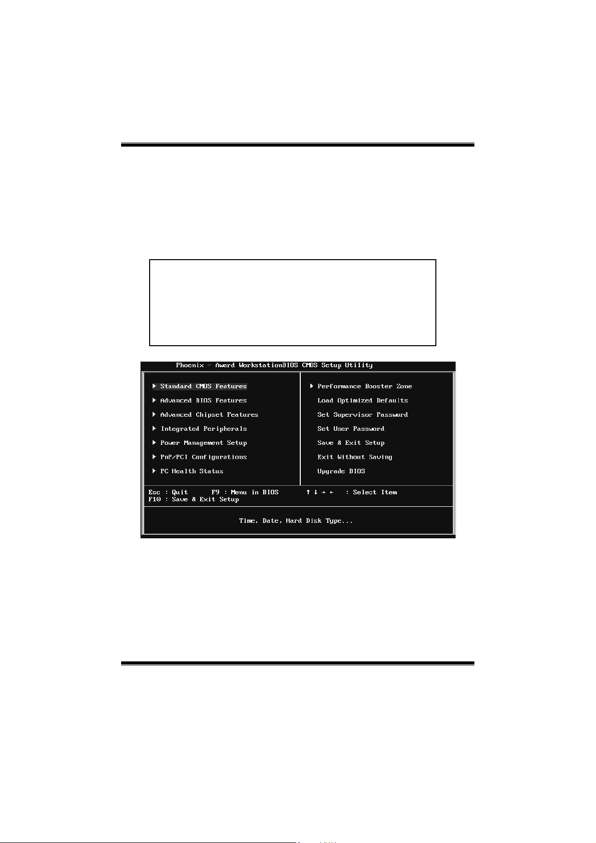
1 Main Menu
Once you enter Phoenix-Award BIOS™ CMOS Setup Utility, the Main Menu
will appear o n the screen. The Main Menu allo ws you to select from several
setup f unct ions. Use the arrow keys to select amo ng t he items and press <Enter>
to accept and enter the sub-menu.
!! WARNING !!
For better system performance, the BIOS firmware is being
continuously updat ed. The BIOS inf or mat ion d esc ribed in
this manual (Figure 1, 2, 3, 4, 5, 6, 7, 8, 9) is for yo ur
reference only. The actual BIOS information and settings on
board may be slightly different from this manual.
Figure 1: Main Menu
Standard CMO S Features
This submenu contains industry standard configurable options.
3
Page 5

NF520-A2 TE/NF520-A2 SE/NF520-A 2
Advanced BIOS Features
This submenu allows you to configur e advanc ed feat ures of the BIOS.
Advanced Chipset Features
This submenu allows you to configure sp ecial chipset features.
Integrated Peripherals
This submenu allows you to configure certain IDE hard drive options and
Programmed Input/ Output features.
Power Management Setup
This submenu allows you to configure the power management features.
PnP/PCI Configurations
This submenu allows you to configure certain “Plug and Play” and PCI options.
PC Health Status
This submenu allows you to monito r the hardware of your s ystem.
Performance Booster Zone
This submenu allows you to change CPU Vcore Voltage and CPU/PCI clock.
(However, we suggest you to use the default setting. Changing the voltage and
cloc k improperly may damage the CPU o r M/B!)
Load Optimized Defaults
This selection allows you to reload the BIOS when prob lem occurs during
system booting sequenc e. These configurations are factory settings optimized
for this system. A confirmation message will be displayed befo re defaults are
set.
4
Page 6

NF520-A2 TE/NF520-A2 SE/NF520-A 2
Set Supervisor Password
Setting the supervisor password will prohibit everyone except the s uperviso r
from making c hanges using the CMOS Setup Utility. You will be prompted with
to ent er a password.
Set User Password
If the Supervisor Passwo rd is not set, then the Us er Pass word wil l function in
the same way as the S up ervisor Pass word. If the Superviso r Password is set and
the Us er Pass word is set, the “Us er” will o nly be able to view configurations but
will not be able to change them.
Save & Exit Setup
Save all configuration changes to CMOS (memory) and exit setup. Confirmation
message will be displayed before proceeding.
Exit Without Saving
Abandon all changes made during the current session and exit setup.
Confirmation message will be displayed before proceeding.
5
Page 7

NF520-A2 TE/NF520-A2 SE/NF520-A 2
Upgrade BIOS
This submenu allows you to upgrade bios.
6
Page 8
NF520-A2 TE/NF520-A2 SE/NF520-A 2
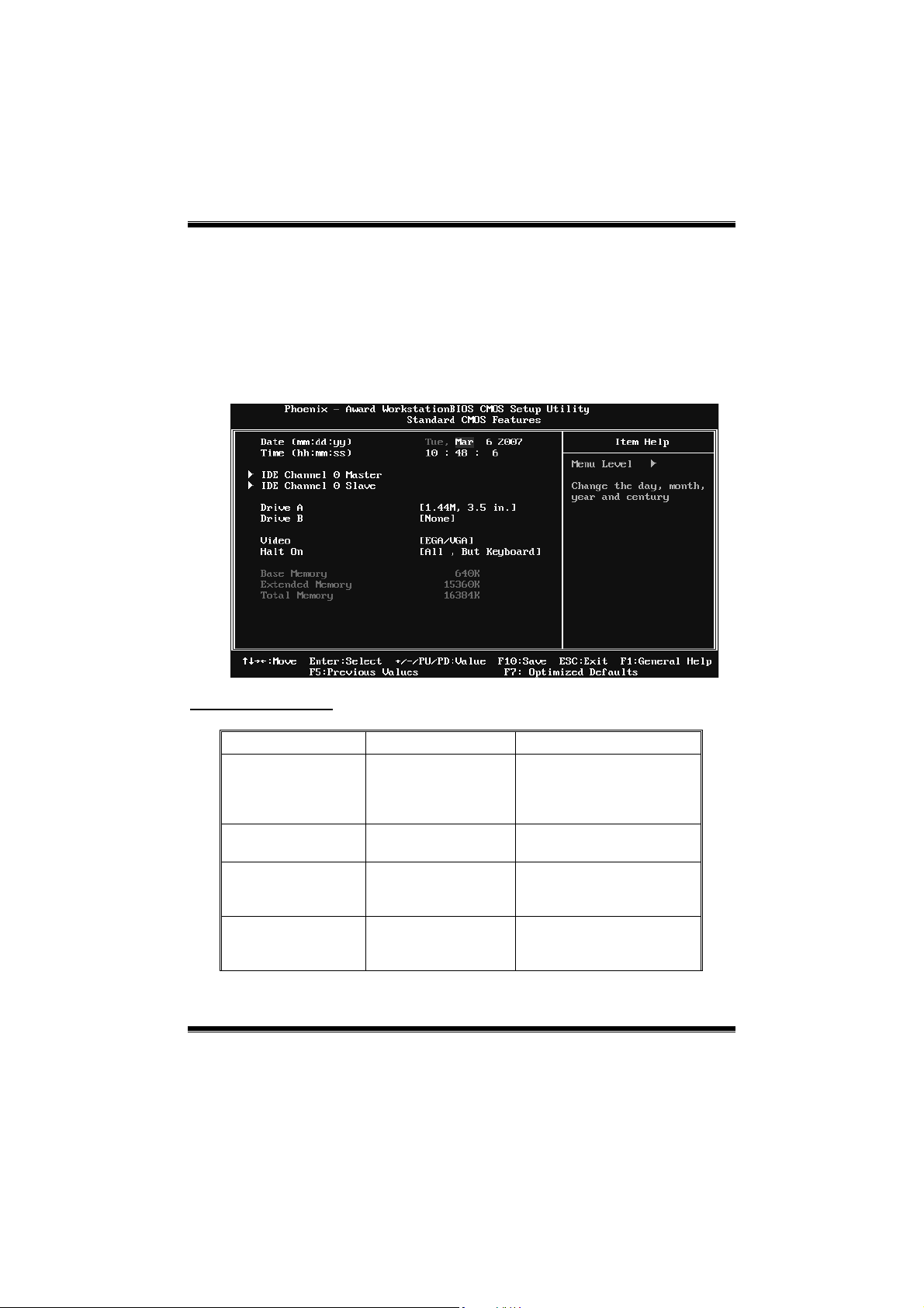
2 Standard CMOS Features
The items in Standard CMOS Setup Menu are divided into several categories.
Each category includes no, o ne o r more than one setup items. Use the arro w
keys to highlight the item and then use the<PgUp> or <PgDn> keys to select the
value you want in each item.
Figure 2: Standard CMOS Setup
Main Menu Selections
This table sho ws the items and the available options on the Main Menu.
Item Options Description
Date mm : dd : yy
Time hh : mm : ss
IDE Channel 0 Master
IDE Channel 0 Slave
Options are in its sub
Options are in its sub
menu.
menu.
Set the system date. Note
that the ‘Day’ automatically
changes when you set the
date.
Set the system internal
clock.
Press <Enter> to enter the
sub menu of detailed
options
Press <Enter> to enter the
sub menu of detailed
options.
7
Page 9

NF520-A2 TE/NF520-A2 SE/NF520-A 2
Item Options Description
360K, 5.25 in
1.2M, 5.25 in
Drive A
Drive B
Video
Halt On
Base Memory N/A
Extended Memory N/A
Total Memory N/A
720K, 3.5 in
1.44M, 3.5 in
2.88M, 3.5 in
None
EGA/ VG A
CGA 40
CGA 80
MONO
All Errors
No Error s
All, but Keyboard
All, but Diskette
All, but Disk/ Key
Select the type of floppy
disk drive installed in your
system.
Select the default video
device.
Select the situation in which
you want the BIOS to stop
the POST process and
notify you.
Displays the amount of
conventional memory
detected during boot up.
Displays the amount of
extended memory detected
during boot up.
Displays the total memory
available in the system.
8
Page 10
NF520-A2 TE/NF520-A2 SE/NF520-A 2
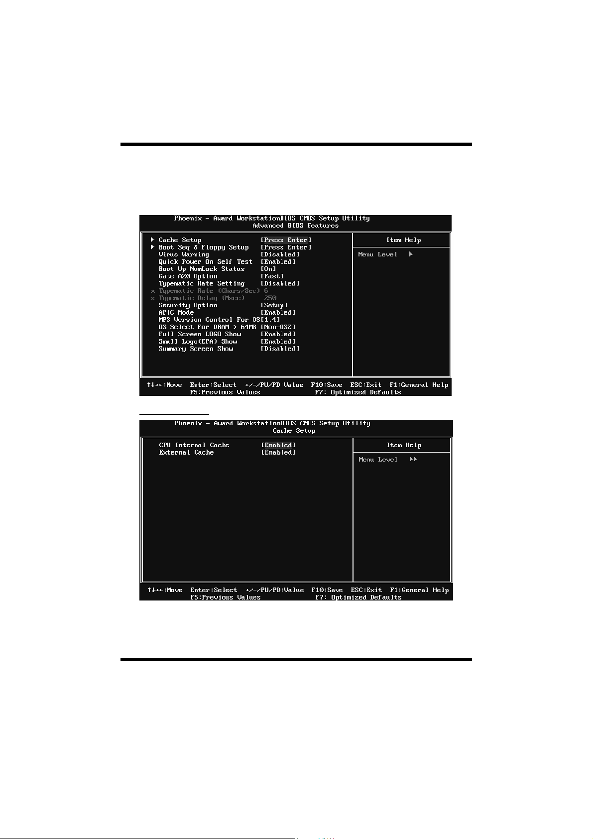
3 Advanced BIOS Features
Figure 3: Advanced BIOS Setup
Cache Setup
9
Page 11
NF520-A2 TE/NF520-A2 SE/NF520-A 2
CPU Internal Cache
Depending on the CPU/chipset in use, you may be able to increase memory
ac ces s tim e with this opt io n.
Enabled (default) Enable cache.
Disabled Disable cache.
External Cache
This option enables or disables “Level 2” secondary cache on the CPU, which
may improve performance.
Enabled (default) Enable cache.
Disabled Disable cache.
Boot Seq & Floppy Setup
This item allows you to setup boot sequence & Floppy.
10
Page 12
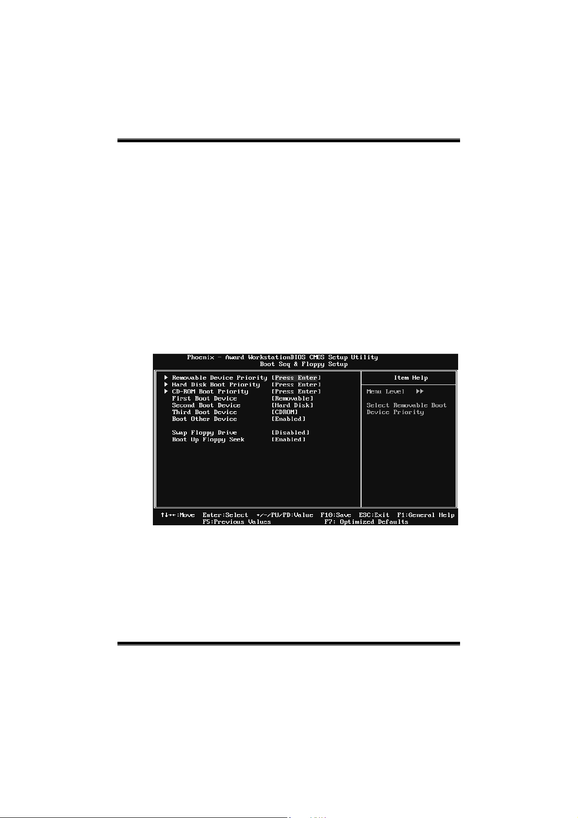
NF520-A2 TE/NF520-A2 SE/NF520-A 2
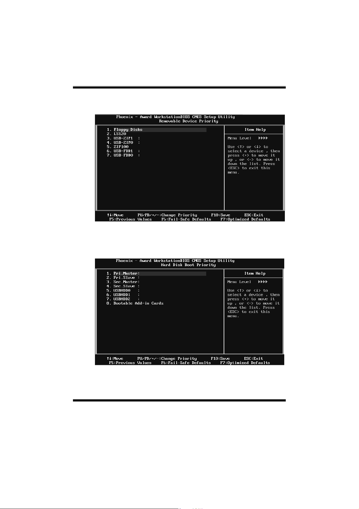
Removable Device Prior ity
Select Removable Boot Device Priority.
The Choices: Floppy Disks, Zip100, USB-FDD0, USB-FDD1, USB-ZIP0,
USB-ZI P1, LS 120.
Hard Disk Boot Priority
The BIOS will attempt to arrange the Hard Disk boot s equence automatic ally.
You can change the Hard Disk booting sequence here.
The Choices: Pri. Master, Pri. S lave, Sec. Master, Sec. Slave, USB HDD0, USB
HDD1, US B HDD2, and Bootable Add-in Cards.
11
Page 13
NF520-A2 TE/NF520-A2 SE/NF520-A 2
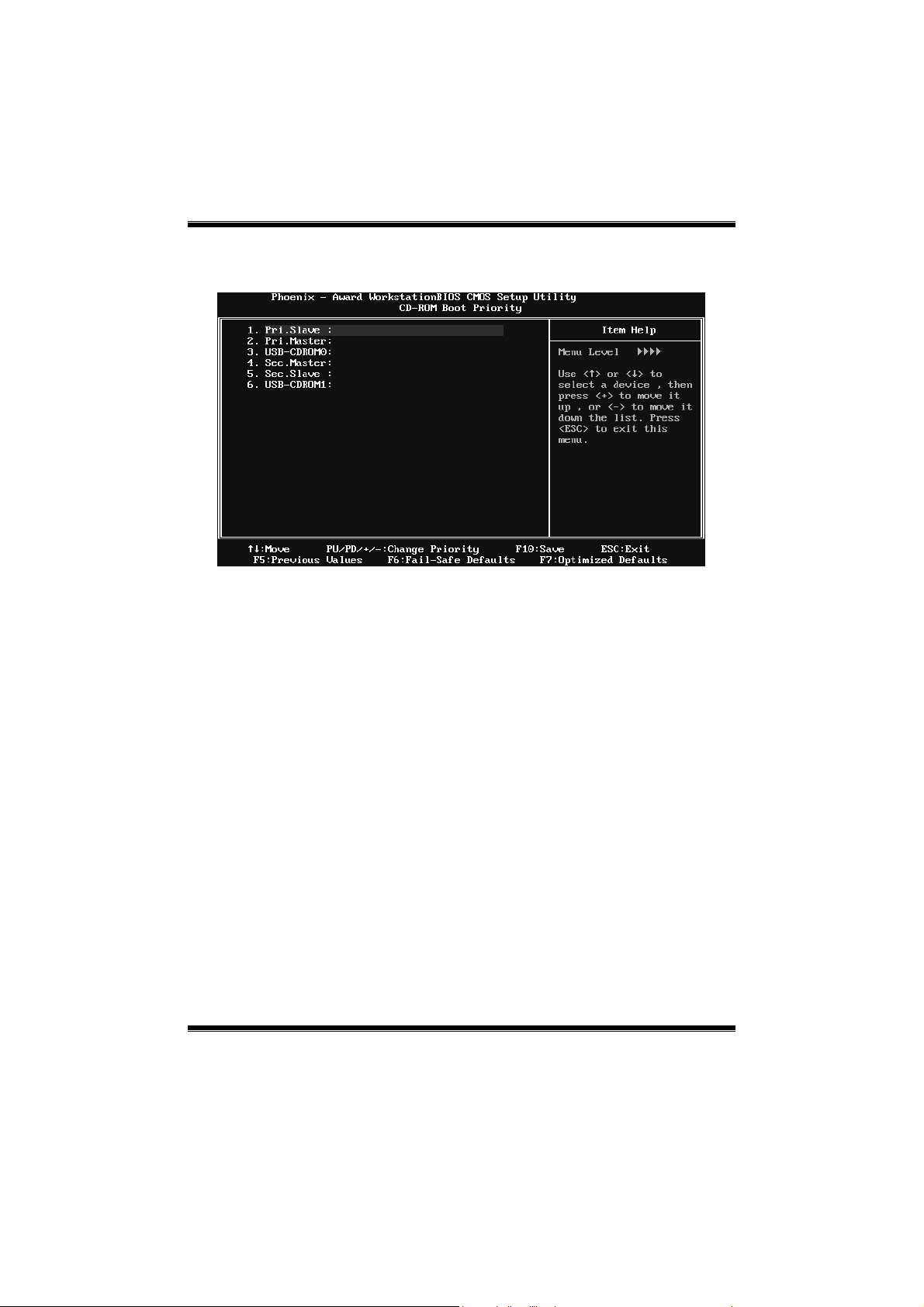
CD-ROM Boot Pr iority
Choices: Pri. Master, Pri. Slave, Sec. Maste r, Se c. Slave, USB CDROM0, USB
CDROM 1.
First/Second/Third Boot Device
The BIOS will attempt to load the operating system in this order.
The
The Choices: Removable, Hard Disk, CDROM, Legacy LAN, Disabled.
Boot Other Device
When enabled, BIOS will try to load the operating system from other device
when it failed to load from the three devices above.
The Choices: Enabled (default), Disabled
Swap Floppy Drive
For systems with two floppy drives, this option allows you to swap logical
drive assignments.
The Choices: Disabled (default), Enabled.
12
Page 14

NF520-A2 TE/NF520-A2 SE/NF520-A 2
Boot Up Floppy Seek
When enabled, System will test the floppy drives to determine if they have 40
or 80 tracks during boot up. Disabling this option reduces the time it takes to
boot-up.
The Choices: Enabled (default), Disabled.
Virus Warning
This option allows you to c hoose the VIRUS Warning feature that is used to
protec t the IDE Hard Disk boot sector. If this function is enabled and an attempt
is made to write to t he boot sector, BIOS will disp lay a warning message on the
screen and sound an alarm beep.
Disabled (default) Virus protection is disabled.
Enabled Virus protection is activated.
Quick Power On Self Test
Enabling this option will cause an abridged version of the Power On Self-Test
(POS T) to execute after you power up the computer.
Disabled Normal POST.
Ena bled (default) Enable quick POST.
Boot Up NumLock Status
Selec ts t he NumLock S t ate after the s ystem s witc hed o n.
The Cho ices:
On (def ault) Numpad is number keys .
Off Numpad is arrow keys.
Gate A20 Option
Select if chipset or keyboard controller should control Gate A20.
Normal A pin in the keyboard controller controls GateA20.
Fast (default) Lets chipset control Gate A20.
Typematic Rate Setting
When a key is held down, the keystroke will repeat at a rate determined by the
keyboard controller. When enabled, the typematic rate and typematic delay can
be configured.
The Choices: Disabled (default), Enabled.
13
Page 15

NF520-A2 TE/NF520-A2 SE/NF520-A 2
Typematic Rate (Chars/Sec)
Sets the rate at which a keyst roke is r epeated when you ho ld the key down.
The Choices: 6 (default), 8, 10, 12, 15, 20, 24, 30.
Typematic Delay (Msec)
Sets the d elay time af ter the key is held do wn before it b egins to repeat the
keystroke.
The Choices: 250 (default), 500, 750, 1000.
Security Option
This option will enable only individuals with passwords to bring the system
online and/or to use the CMOS Setup Utility.
System: A pass word is required for the system to boot and is also
required to access the Setup Utility.
Setup (default): A pass word is required to access the Setup Utility only.
This will o nly apply if passwords are set from the Setup main menu.
APIC MODE
Selecting Enabled enab les APIC device mode reporting from the BIOS to the
operating system.
The Choices: Enabled (default), Disabled.
MPS Version Control For OS
The BIOS supports version 1.1 and 1.4 of the Intel multiprocessor specification.
Selec t vers ion supported by the operatio n sys tem running on t his comput er.
The Choices: 1.4 (default), 1.1.
OS Select For DRAM > 64MB
A choice other than Non-OS2 is only used for OS2 systems with memory
exceeding 64MB.
The Choices: Non-OS2 (default), OS 2.
14
Page 16

NF520-A2 TE/NF520-A2 SE/NF520-A 2
Full Screen Logo Show
This item allows you to select whether the “F ull Screen Lo go” shows. Enabled
(default) “Full Screen Logo” shows when system boots up. Disabled No “Full
Screen Logo” shows when system boots
The Choices: Enabled (default), Disabled.
Small Logo(EPA) Show
This item allows you to select whether the “Small Logo” shows. Enabled
(default) “Small Logo” shows when system boots up. Disabled No “Small
Logo” shows when system boots
The Choices: Enabled (default), Disabled.
Summary Screen Show
This item allows you to enab le/disable the summary screen. S ummary screen
means system configuration and PCI device listing.
The Choices: Disabled (default), Enabled.
15
Page 17

NF520-A2 TE/NF520-A2 SE/NF520-A 2
4 Advanced Chipset Features
This sub menu allows you to configure the specific features of the c hipset
installed on your system. This chipset manage bus speeds and access to system
memory resources, such as DRAM. It also coordinates communications with the
PCI bus. The default sett ings t hat came with your system have been optimized
and t her efore s hould no t be changed unless you ar e susp icious that the settings
have been changed incorrectly.
Figure 4: Advanced Chipset Setup
K8<->NB HT Width
This item allows you to select t he K8<-> NB HT W idth.
The Choices: Auto(def ault ), [↓16 ↑16],[↓8 ↑ 8].
PCIE/SATA Spread Spectrum
This item allows you to enab le/disable the Spread Spectrum function.
The Choices: Disabled (default), Triangular Down.
16
Page 18

NF520-A2 TE/NF520-A2 SE/NF520-A 2
HT Spread Spectrum
This item allows you to select HT Spread Spectrum functio n.
The Choices: Disabled (d efault), 0. 50% H. Kiss Cntr, 0.75% H. Kiss Cntr,
0.50% T riang. Center, 0.75% Tr iang. Center.
SSE/SSE2 Instructions
This item allows you to enab le/disab le S SE/S S E2 ins truction.
The Choices: Enabled (default), Disabled.
CPU Feature
Virtualiza tion
This option allows you to enable or disable Virtualization function.
The Choices: Disabled (default), Enabled.
AMD K8 Coo l&Quiet control
The item allows you to control the K8 Cool’n’Quiet function.
The Choices: Auto (default), Disabled.
17
Page 19

NF520-A2 TE/NF520-A2 SE/NF520-A 2
System BIOS Cacheable
Selec t ing the “ Enabled ” op tion allo ws caching of t he s ystem BIOS ROM at
F0000h-FFFFFh, which is able to improve the sys tem performance. However,
any p rograms that attempts to write to this memory block will cause conflic ts
and result in s ystem errors.
The Choices: Disabled (default), Enabled.
18
Page 20
NF520-A2 TE/NF520-A2 SE/NF520-A 2
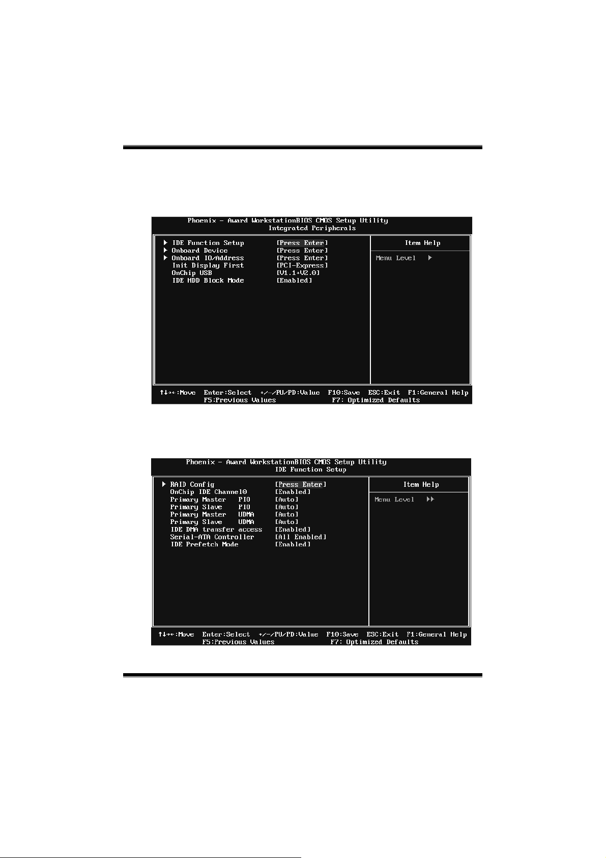
5 Integrated Peripherals
Figure 5. Integrated Peripherals
IDE Function Setup
Highlight the “Press Enter” label next to the “IDE Function Setup” label and
pr ess e nter key will take you a s ubmenu with the following op t ions:
19
Page 21

NF520-A2 TE/NF520-A2 SE/NF520-A 2
RAID Config
RAID Enable
This option allows you to enable or disable R AID function.
The Choices: Disabled (default), Enabled.
SATA 1 Primary/Secondary RAID
This option allows you to enable or disable SATA 1 Primary/Secondary RAID.
The Choices: Disabled (default), Enabled.
On-chip IDE C hanne l 0
The motherboard chipset contains a PCI IDE interface with support for two
IDE channels. Select “Enabled” to activate the first and/or second IDE interface.
Select “Disabled” to deactivate an interface if you are going to install a primary
and/or secondary add-in IDE interface.
The Choices: Enabled (default), Disabled.
Primary Master/S lave PIO
The IDE PIO (P rogrammed Input / Output) fields let you set a PIO mode (0-4)
for each of the IDE devices that the onboard IDE interface supports. Modes 0
to 4 will inc rease performance p rogr ess ive ly. In Auto mo de, the system
automatically determines the best mode for each device.
The Choices: Auto (default), Mode0, Mode1, Mode2, Mode3, Mode4.
20
Page 22

NF520-A2 TE/NF520-A2 SE/NF520-A 2
Primary Master/S lave UDMA
Ultra DMA function can be implemented if it is supported by the IDE hard
drives in your system. As well, your operating environment requires a DMA
driver (Windows 95 or OSR2may need a third party IDE bus master driver). If
your hard drive and your system software both support Ultra DMA, select Auto
to enable BIOS support.
The Choices: Auto (default), Disabled.
IDE DMA Transfer Access
This item allows you to enable or disable the IDE DMA transfer access.
The Choices: Enabled (default), Disabled.
Serial-AT A Controller
This item allows you to enable or disable the Serial ATA function.
The Choices: All Enabled (default), Disabled.
IDE Prefetch Mode
The “onboard” IDE drive interfaces supports IDE prefetch function for faster
drive access. If the interface on your drive does not support prefetching, or if
you install a primary and/or secondary add-in IDE interface, set this option to
“Disabled”.
The Choices: Enabled (default), Disabled.
21
Page 23
NF520-A2 TE/NF520-A2 SE/NF520-A 2
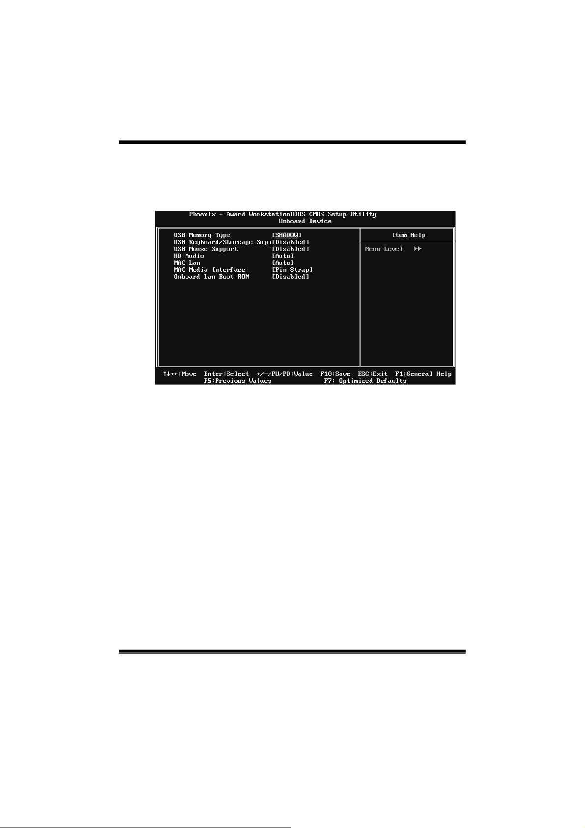
Onboard Device
Highlight the “Press Enter” label next to the “Onboard Device” label and press
the enter key will take you a submenu with the following opt ions :
USB Memory Type
The Choices: SHADOW (default), Base Memory(640K).
USB Keyboard/Storage Support
This item allows you to enable or disable the USB Keyboard / Storage Legacy
Support.
Enabled Enable USB Keyboard / Storage Support.
Disabled (default) Disab le USB Keyboard/ Storage Support.
USB Mouse Support
This item allows you to enable or disable the USB Mouse Legacy Support.
Enabled Enable USB Mouse Support.
Disabled (default) Disable USB Mouse Support.
HD Audio
This option allows you to control the onboard HD audio.
The Choices: Auto (default), Disabled.
22
Page 24

NF520-A2 TE/NF520-A2 SE/NF520-A 2
MAC LAN
This option allows you to control the onboard MAC LAN.
The Choices: Auto (default), Disabled.
MAC Media Interface
This option allows you to control the onboard MAC Media Interface.
The Choices: Pin Strap (default), MII, RGMII.
Onboard LAN Boot ROM
This item allows you to enable or disable the Onboard LAN Boot ROM.
The Choices: Disabled (default), Enabled.
Onboard I/O Address
Press Enter to configure the Onboard I/O Address.
Onboard FDC Controller
Select enabled if your system has a floppy disk controller (FDC) insta lled on
the system board and you wish to use it. If you installed another FDC or the
system uses no floppy drive, select disab led in this field.
The Choices: Enabled (default), Disabled.
23
Page 25

NF520-A2 TE/NF520-A2 SE/NF520-A 2
Onboard Serial Port 1
Select an address and corresponding interrupt for the first and second serial
ports.
The Choices: 3F8/IRQ4 (default), Disabled, 2F8/IRQ3, 3E8/IRQ4, 2E8/IRQ3,
Auto.
Onboard Parallel Por t
This item allows you to determine access onboard parallel port controller with
which I/O Address.
The Choices: 378/IRQ7 (default), 278/IRQ5, 3BC/IRQ7, Disabled.
Parallel Port Mode
This item allows you to determine how the parallel port should function. The
default value is SPP.
The Choices:
SPP (def au lt) Usin g Parallel po rt a s St an dard P rin te r P ort.
EPP Usin g Parallel P ort as Enhan ce d P a ra llel P ort.
ECP U sin g Parallel port as Ext end ed Capabilities P ort.
ECP+EPP Usin g Pa rallel port as ECP & EPP mod e.
ECP Mode Use DMA
Init Display First
This item allows you to dec ide to active whether PCI Slot o r on-chip VGA first.
The Choices: PCI-Express (default), PCI S lot.
OnChip USB
This option should be enabled if your system has a USB installed o n the system
board. You may need to dis able this feature if you add a higher performance
controller.
The Choices: V1.1+V2.0 (def ault), Disabled, V1.1
Select a DMA Channel for the port.
The Choices: 3 (default), 1.
24
Page 26

NF520-A2 TE/NF520-A2 SE/NF520-A 2
IDE HDD Block Mode
Block mode is also called b lock transfer, multiple commands, or multiple
sectors read / write. If your IDE hard drive supports block mode (most new
drives do), select Enabled for automatic detect ion of the optimal number of
block mode (most new drives do), select Enab led for automatic detect ion of the
optimal number of block read / write per sector where the drive can support.
The Choices: Enabled (default), Disabled.
25
Page 27

NF520-A2 TE/NF520-A2 SE/NF520-A 2
6 Power Management Setup
The Power Management Setup Menu allows you to configure your system to
utilize energy conservation and power up/power down features.
Figure 6. Power Manageme nt Setup
ACPI Function
This item dis p lays the status of the Adva nced Configur ation and Po wer
Management (ACPI).
The Choices: Enabled (default), Disabled.
ACPI Suspend Type
The item allows you to s elect the suspend typ e under the ACPI operating
system.
The Choices: S1 (POS) (default ) Power o n Susp end
S3 (STR) Suspend to RAM
S1 & S3 POS+STR
26
Page 28

NF520-A2 TE/NF520-A2 SE/NF520-A 2
Power Management
This category allows you to select the power s aving method and is directly
relat ed to the follo win g mod es :
1. HDD Po wer Down.
2. Suspend Mode.
There are three options of Power Management, three of which have fixed mode
settings
Min. Saving
Minimum power management.
Suspend Mode = 1 hr.
HDD Power Down = 15 min
Max. Saving
Maximum power management only available for s l CPU’s.
Suspend Mode = 1 min.
HDD Power Down = 1 min.
Use r De fi ne (d efault)
Allow yo u to set each option individ ually.
When you choose user define, you can adjust each of the item from 1 min. to 1
hr. except for HDD Power Down which ranges from 1 min. to 15 min.
Video Off Method
This option determines the manner when the monitor goes blank.
V/H SYNC+Blank
This selection will cause the sys tem to turn off the vertical and horizontal
synchronization ports and write blanks to the video buffer.
Blank Screen
This option only writes blanks to the video buffer.
DPM S Suppo r t (default)
Initial display power management s ignaling.
HDD Power Down
Whe n enab led, the hard -disk drives will power do wn after a set time of syst em
inactivity. All other devices remain active.
The Choices: Disabled (default), 1 Min, 2 Min, 3 Min, 4 Min, 5 Min , 6 Min, 7
Min, 8 Min, 9 Min, 10 Min, 11 Min, 12 Min, 13 Min, 14 Min, 15Min.
27
Page 29

NF520-A2 TE/NF520-A2 SE/NF520-A 2
Soft-Off by PBTN
This item determines the behavior of system power button. Instant o ff turn off
the po wer i mmed iately, and Delay 4 Sec. will req uire you to p r ess a nd ho ld the
power button for 4 s econds to cut off t he system power.
The Choices: Delay 4 Sec, Instant-Off (default ).
WOL(PME#)/ From Soft-Off
This item allows you to enab le o r disable Wake O n LAN from Soft-Off
function.
The Choices: Disabled (default), Enabled.
WOR(RI#) From Soft-Off
This item allows you to enab le o r disable Wake O n Ring fro m Soft-Off function.
The Choices: Disabled (default), Enabled.
USB Resume From S3/S4
This item allows you to enable o r disabled the US B res ume from S3/S4
function.
The Choices: Disabled (default), Enabled.
Power-On by Alarm
This function is for setting date and time for your computer to boot up. When
enabled, you can choos e the date and time to boo t up the system.
The Choices: Disabled (default), Enabled.
Date (of Month) Alarm
You c an c hoose which month the sys tem wil l boot up .
Time (hh:mm:ss) Alarm
You c an c hoose the system boot up t ime, input ho ur, minute and sec o nd to
specify.
Note : If yo u have change the se tting, you must let the system boot up until it
goes to the operating s ystem, before this function will work.
28
Page 30

NF520-A2 TE/NF520-A2 SE/NF520-A 2
HPET Support
This option allows you to dis abled or enab les the High Precision Event T imer.
The Choices: Enabled (default), Disabled.
POWER ON Function`
This item allows you to choose the power on method.
The Choices: Button Only(default), Password, Hot Key, Mouse Mo ve/Click,
Mouse Double Click, Any Key, Keyboard 98.
KB Power ON Password
Input password and press Enter to set the Keyboard power on password.
Hot Key Power ON
Choos e the Hot Key co mbination to boot up the s ystem.
The Choices: Ctrl-F1(default), Ctrl-F2, Ctrl-F3, Ctrl-F4, Ctrl-F5, Ctrl-F6,
Ctrl-F7, Ctrl-F8, Ctrl-F9, Ctrl-F10, Ctrl-F11, and Ctrl-F12.
PWRON After PWR-Fail
This setting specifies how your system should behave af ter a power fail or
interrupts occurs. By choos ing off wil l leave the co mp uter in the po wer off st ate.
Choos ing On will reboot the computer. Fo rmer-Sts will restore the system to the
status befo re po wer failure or interrupt occ urs.
The Choices: Off (default), On, Former-Sts.
29
Page 31

NF520-A2 TE/NF520-A2 SE/NF520-A 2
7 PnP/PCI Configurations
This section describes configuring the PCI bus system. PCI, or Personal
Computer Interconnect, is a s ystem which allo ws I/O devic es to operat e at
speeds nearing the speed of the CPU itself us es when communicating with its
own special components. This section covers some very technical items and it is
strongly recommended that only experienc ed users should make any changes to
the default settings.
Figure 7: PnP/PCI Configurations
30
Page 32

NF520-A2 TE/NF520-A2 SE/NF520-A 2
Reset Configuration Data
The s ystem BIOS s uppo rts the PnP feature which requires the system to record
whic h resourc es are assigned and protects resources from conflict.
Every per ipheral device has a node, whic h is called ESCD. This nod e records
whic h reso urc es a re as s igned to it. T he system needs to record and update ESCD
to the memor y loca tio ns. T hes e locations are reserved in the system BIOS. If the
Disabled (default) option is chosen, the system‘s ESCD will update only when
the ne w configuration varies fro m the last one. If the Enabled option is c hos e n,
the system is forced to update ESCDs and then is automatically set to t he
“Disabled” mode.
The above settings will be shown on the screen only if “Manual” is chosen for
the resourc es c ont ro lled by function.
Legac y is the term, whic h s ignifies that a reso urce is ass igned to the ISA Bus
and provides non-PnP ISA add-o n cards. PCI / ISA PnP signify that a resource
is assigned to the PCI Bus or provid es for ISA PnP add-on cards and
peripherals.
The Choices: Disabled (default), Enabled.
Resources Controlled By
By Choos ing “Auto(ESCD)” (default), the system BIOS will detect the system
resources and automatically assign the relative IRQ and DMA channel for each
perip heral. By Choosing “Manual”, the us er will need to ass ign IRQ & DMA for
add-on cards. Be sure that there are no IRQ/DMA and I/O port conflicts.
The Choices: Auto (ESCD) (default), Manual.
IRQ Resources
This sub menu will allow you to assign each syst em interrupt a type, d epending
on the type of device us ing the interrupt. When you press the “Press Ente r” tag,
you will be directed to a sub men u that wi ll allo w you to co nfigure the system
interrupts. T his is only configurable when “Resources Controlled By” is set to
“Manual”.
IRQ-5 ass igned to PCI Device
IRQ-7 ass igned to PCI Device
IRQ-9 ass igned to PCI Device
IRQ-10 ass igned to PCI Device
IRQ-11 ass igned to PCI Device
IRQ-14 ass igned to PCI Device
IRQ-15 ass igned to PCI Device
31
Page 33

NF520-A2 TE/NF520-A2 SE/NF520-A 2
PCI / VGA Palette Snoop
Some old grap hic controllers need to “snoop” on the VGA palette and then map
it to their disp lay as a way to provide boot info rmation and VG A compatibility.
This item allows such snoop ing to take place.
The Choices: Disabled (default), Enabled
Ma xi mu m Pa ylo ad Siz e
Set t he maximum payload s ize fo r Transac tio n packets (TLP ).
The Choice: 4096 (default.), 128, 256, 512, 1024, 2048.
32
Page 34

NF520-A2 TE/NF520-A2 SE/NF520-A 2
8 PC Health Status
Figure 8: PC Health Status
Shutdown Temperature
This item allows you to set up the CPU s hutdown Temperature. This item is
only effective under Windows 98 ACPI mode.
The Choices: Disabled , 60℃/ 140℉, 65℃/ 149℉, 70℃/ 158℉, 75℃/ 167℉,
80℃/ 176℉(default), 85℃/ 185℉, 90℃/ 167℉.
Show H/W Monitor in POST
If you computer co ntains a monitoring system, it will s how PC health status
during POST stage. The item offers several different delay times.
The Choices: Enabled (default), Disabled.
CPU FAN Control by
Choose “ s mart” to r educ e t he no ise caus ed by CPU FAN.
The Choices: Smart, Always On (default).
33
Page 35

NF520-A2 TE/NF520-A2 SE/NF520-A 2
CPU Fan Off<℃>
If the CPU Temperature is lower than the set value, F AN will turn o ff.
The Choices: Min= 0, Max= 127, key in a DEC number.
CPU Fan Start<℃>
CPU fan starts to work under s mart fan func tion when arrive this set value.
The Choices: Min= 0, Max= 127, key in a DEC number.
CPU Fan Full speed <℃ >
Whe n CPU temperature is re ach the s et value, the CP U fan wil l work under Full
Speed.
The Choices: Min= 0, Max= 127, key in a DEC number.
Start PWM Value
Whe n CPU temperatur e arrives to the set valu e, the CP U fa n will work under
Smart Fan Function mode. The range is from 0~127, with an interval of 1.
The Choices: Min= 0, Max= 127, key in a DEC number.
CPU Vcore, Chipset Volt, +3.3V, +5.0V, +12.0V, DDR Voltage,
HT Voltage, 5V<SB>, Voltage Battery
Detect t he sys t em’s voltage status automatically.
CPU Temp
This field disp lays the c urr ent temperatur e of CPU.
Current CPU FAN Speed
This field disp lays the c urrent sp eed of CP U fan.
Current SYS FAN Speed
This field disp lays the c urr ent sp eed SYST EM fan.
34
Page 36
NF520-A2 TE/NF520-A2 SE/NF520-A 2
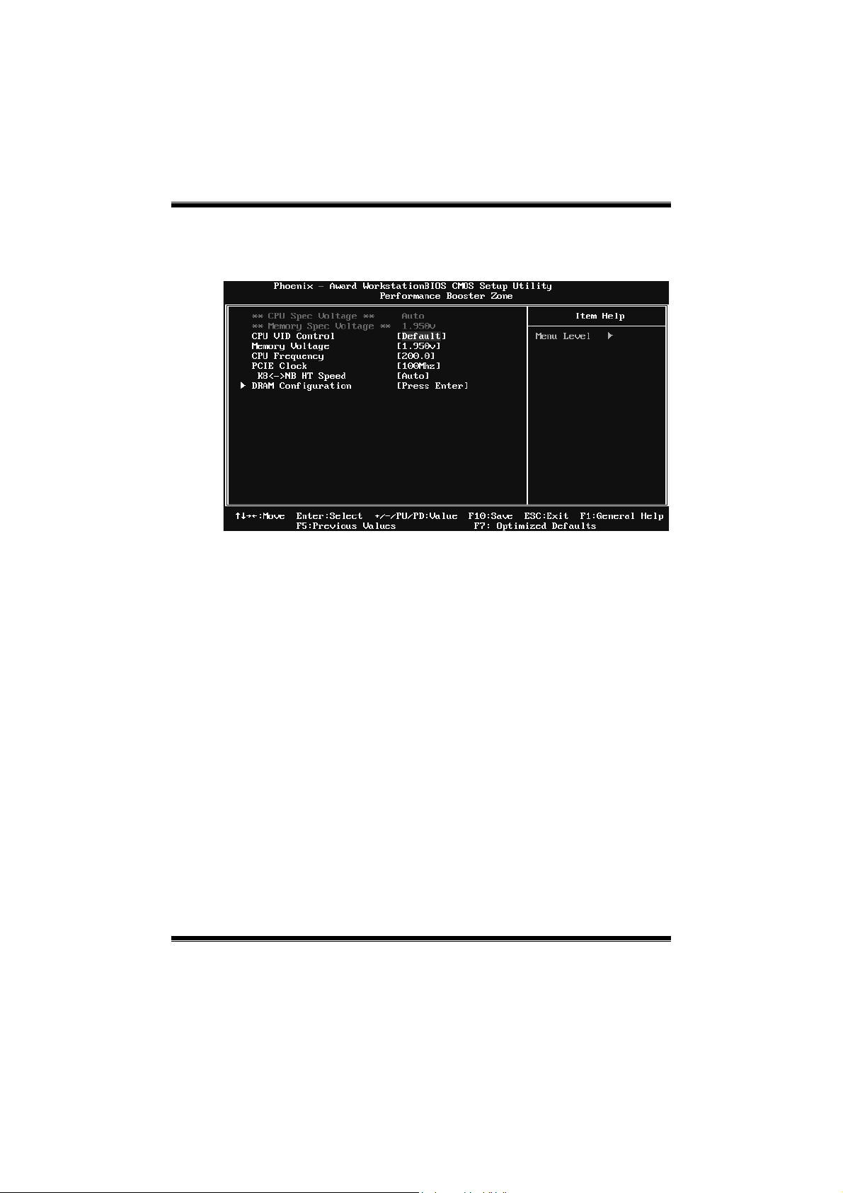
9 Performance Booster Zone
CPU VID Control
The Choices: Default (default), +3.3%, +6.6%, +10%.
Memory Voltage
The Choices: 1.950V (default), 2.000V, 2.050V, 2.100V.
CPU Frequency
This item allows you to select t he CPU F requency.
The Choices: 200 (default), 20 1~450.
PCIE Clock
The Choices:100Mhz (default), 100Mhz-150Mhz.
K8<->NB HT Speed
The Choices: AUTO (default), 1x, 2x, 3x, 4x, 5x.
35
Page 37

NF520-A2 TE/NF520-A2 SE/NF520-A 2
DRAM Configuration
Memor y T i mi ngs
tCL(CAS Latency )
The Choices: Auto (default), 3 clock ~ 6 clock.
36
Page 38

NF520-A2 TE/NF520-A2 SE/NF520-A 2
tRCD
The Choices: Auto (default), 3 clock ~ 6 clock.
tRP
The Choices: Auto (default), 3 clock ~ 6 clock.
tRAS
The Choices: Auto (default), 5 clock ~ 18 clock.
Command Per Clock (CMD)
The Choices: Auto (default), 1 clock ~ 2 clock.
tRRD
The Choices: Auto (default), 2 clock ~ 5 clock.
AsyncLat
The Choices: Auto (default), 1ns ~ 15ns.
tRC
The Choices: Auto (default), 11 clock ~ 26 clock.
tWR
The Choices: Auto (default), 3 clock ~ 6 clock.
tRWT
The Choices: Auto (default), 2 clock ~ 9 clock.
tWTR
The Choices: Auto (default), 1 clock ~ 3 clock.
tREF
The Choices: Auto (default), 7.8 us, 3.9 us.
Read DQS Skew
The Choices: Auto (default), -10/96 clock ~ +10/96 clock.
Read delay from Rx FIFO
The Choices: Auto (default), 0.5 clock ~ 4.0 clock.
Trfc0 for DIMM0
The Choices: Auto (default), 75ns, 105ns, 127.5ns, 195ns, 327.5ns.
37
Page 39
NF520-A2 TE/NF520-A2 SE/NF520-A 2
Trfc2 for DIMM2
The Choices: Auto (default) , 75ns, 105ns, 127.5ns, 195ns, 327.5ns.
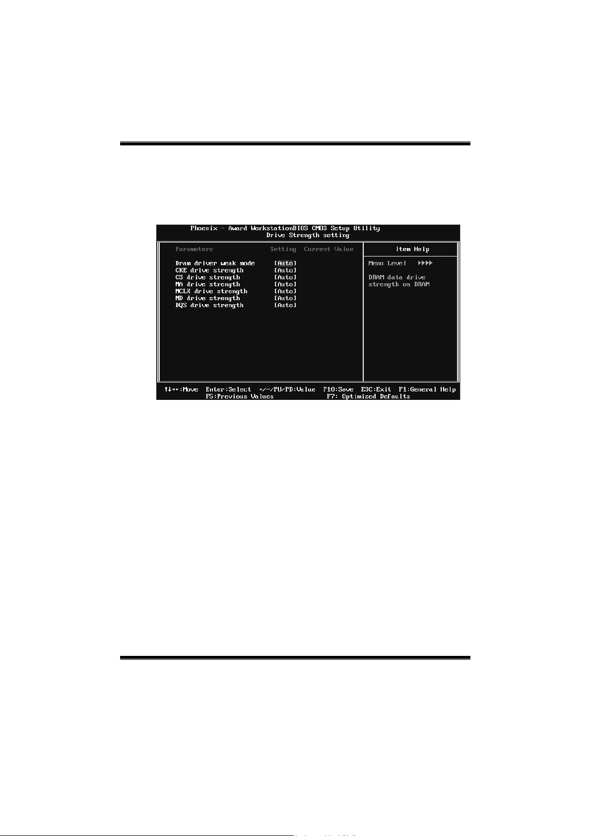
Drive Strength setting
Dram driver weak mode
The Choices: Auto (default), Normal, Weak.
CKE drive strength
The Choices: Auto (default), 1.0x, 1.25x, 1.5x, 2.0x.
CS drive strength
The Choices: Auto (default), 1.0x, 1.25x, 1.5x, 2.0x.
MA drive strength
The Choices: Auto (default), 1.0x, 1.25x, 1.5x, 2.0x.
MCLK drive strength
The Choices: Auto (default), 0.75x, 1.0x, 1. 25 x, 1.50x.
MD drive strength
The Choices: Auto (default), 0.75x, 1.0x, 1. 25 x, 1.50x.
DQS drive strength
The Choices: Auto (default), 0.75x, 1.0x, 1. 25 x, 1.50x.
38
Page 40

NF520-A2 TE/NF520-A2 SE/NF520-A 2
Dram on -die Termination
The Choices: Auto (default), Disable, 75ohm, 150ohm, 50ohm.
Read/Write Queue bypa ss
The Choices: Auto ( default), 2 time s, 4 time s, 8 times, 1 6 times.
Bypass Maximum
The Choices: Auto (default), No bypass, 1 time ~ 15 time.
32 Byte Granular ity
The Choices: Auto (default), 64-byte, 32-byte.
Timing Mode
T his it em allows you to c hoo se to m anually or aut omatically regulate the DD R
Timing.
The Choices: Auto ( def ault), MaxM emC lk.
Memory Clock Value or Limi
The Choices: DDR 400 (default), DDR 533, DDR 667, DDR 800.
DQS Training Control
The Choices: Perform DQS, Skip DQS( def au lt).
CKE base po wer down mode
The Choices: Enabled, Disabled(default).
CKE based powerdown
The Choices: Per Channel (default), Per CS.
Memclock tri-stating
The Choices: Disabled (default), Enabled.
Memory Hole Remapping
The Choices: Enabled (default), Disabled.
Auto Optimize Bottom IO
The Choices: Enabled (default), Disabled.
Bottom of [31:24] IO space
The Choices: C0 (default), Min=0000, Max=00FF, Key in a HEX number.
39
 Loading...