

Page 1
Biolistic®PDS-1000/He
Particle Delivery System
Catalog Numbers
165-2257 and
165-2250LEASE
to 165-2255LEASE
For Technical Service Call Your Local Bio-Rad Office or in the U.S. Call 1-800-4BIORAD (1-800-424-6723)
Page 2

Warranty and Regulatory Notices
Warranty Statement
This warranty may vary outside of the continental United States. Contact your local Bio-Rad
office for the exact terms of your warranty.
Bio-Rad Laboratories warrants that the Biolistic PDS-1000/He system (catalog numbers
165-2257 and 165-2250LEASE to 165-2255LEASE) will be free from defects in material
and workmanship, and will meet all performance specifications for the period of 1 year from
the date of shipment. This warranty covers all parts and labor.
In the event that the instrument must be returned to the factory for repair under warranty, the instrument must be packed for return in the original packaging.
Bio-Rad shall not be liable for any incidental, special, or consequential loss, damage, or
expense directly or indirectly arising from the use of the Biolistic PDS-1000/He system. BioRad makes no warranty whatsoever in regard to products or parts furnished by third parties,
such being subject to the warranty of their respective manufacturers. Service under this warranty shall be requested by contacting your nearest Bio-Rad office.
The following items are considered customer-installed consumables: fuses, microcarriers,
macrocarriers, and rupture disks. These parts are not covered by this warranty. All customerinstalled parts are warranted only to be free from defects in workmanship.
This warranty does not extend to any instruments or parts thereof that have been subject
to misuse, neglect, or accident, or that have been modified by anyone other than Bio-Rad or
that have been used in violation of Bio-Rad instructions.
The foregoing obligations are in lieu of all other obligations and liabilities including negligence
and all warranties, of merchantability, fitness for a particular purpose or otherwise, expressed or
implied in fact or by law, and state Bio-Rad’s entire and exclusive liability and buyer’s exclusive
remedy for any claims or damages in connection with the furnishing of goods or parts, their
design, suitability for use, installation, or operation. Bio-Rad will in no event be liable for
any special, incidental, or consequential damages whatsoever, and Bio-Rad’s liability under no
circumstances will exceed the contract price for the goods for which liability is claimed.
Regulatory Notices
Important: This Bio-Rad instrument is designed and certified to meet EN55011,
EN50082-1, and IEC 1010-1 requirements, which are internationally accepted electrical safety standards. Certified products are safe to use when operated in accordance with the instruction manual. This instrument should not be modified or altered in any way. Alteration of this
instrument will:
Void the manufacturer’s warranty.
Void the regulatory certifications.
Create a potential safety hazard.
Note: This equipment has been tested and found to comply with the limits for a Class A
digital device, pursuant to Part 15 of the FCC rules. These limits are designed to provide reasonable protection against harmful interference when the equipment is operated in a commercial environment. This equipment generates, uses, and can radiate radio frequency energy
and, if not installed and used in accordance with the instruction manual, may cause harmful
interference to radio communications. Operation of this equipment in a residential area is
likely to cause harmful interference in which case the user will be required to correct the interference at his own expense.
Page 3

Table of Contents
Section 1 Biolistic PDS-1000/He Particle Delivery System..............................................1
1.1 Particle Delivery Technology ....................................................................................1
1.2 Overview of PDS-1000/He Particle Delivery System ..............................................1
1.3 Important Safety Information.....................................................................................3
1.4 Requirements for System Operation..........................................................................3
Section 2 Product Description .....................................................................................5
2.1 Packing List ................................................................................................................5
2.2 Identification of Unit Controls and Components ....................................................10
Section 3 Installation ..................................................................................................13
3.1 Connecting the PDS-1000/He System to a Helium Source ....................................13
3.2 Connecting the PDS-1000/He to a Vacuum Source................................................15
3.3 Power Cord/Voltage Regulator................................................................................16
Section 4 Operation of the PDS-1000/He Instrument ............................................17
4.1 Preparation of System Components Prior to Bombardment...................................17
4.2 Performing a Bombardment.....................................................................................22
4.3 Removal of Residual Helium Pressure–Shut Down ...............................................30
Section 5 Selection and Adjustment of System Bombardment Parameters........30
5.1 Overview -Matrix of Variables: Cell Types, Settings and Conditions ...................30
5.2 Vacuum Level in Bombardment Chamber..............................................................31
5.3 Helium Pressure / Rupture Disk Selection ..............................................................31
5.4 Solenoid Valve Adjustment .....................................................................................32
5.5 Vacuum Flow Rate Control Valves.........................................................................32
5.6 Distance Between Rupture Disk and Macrocarrier.................................................32
5.7 Distance Between Macrocarrier and Stopping Screen............................................32
5.8 Distance Between Stopping Screen and Target Shelf
(microcarrier flight distance)....................................................................................32
5.9 Microcarrier Selection..............................................................................................33
5.10 Preparation of Biological Material for Bombardment ............................................34
Section 6 Troubleshooting......................................................................................................37
6.1 Rupture Disk Bursts at Incorrect Pressure...............................................................37
6.2 Stopping Screen Forced Through Screen Support Ring .........................................37
6.3 Excessive Gas Usage................................................................................................38
6.4 Chamber Will Not Hold Vacuum ............................................................................38
6.5 Sample Damage From Gas Pressure Wave .............................................................38
6.6 Unit Will Not Pressurize Gas Acceleration Tube....................................................39
Section 7 Product Information..................................................................................40
7.1 Biolistic System........................................................................................................40
7.2 Spare Parts ................................................................................................................41
Section 8 Appendices ..............................................................................................................43
8.1 Cleaning the PDS-1000/He Device .........................................................................43
8.2 Metal Case Version ..................................................................................................43
8.3 Specifications ...........................................................................................................46
8.4 Performing a Bombardment—Quick Guide Tear-Out............................................47
Page 4
Section 1
Introduction to Particle Delivery
1.1 Particle Delivery Technology
Biolistic particle delivery is a method of transformation that uses helium pressure to introduce DNA-coated microcarriers into cells. Microprojectile bombardment can transform such
diverse targets as bacterial, fungal, insect, plant, and animal cells and intracellular organelles.
Particle delivery is a convenient method for transforming intact cells in culture since minimal
pre- or post-bombardment manipulation is necessary. In addition, this technique is much easier and faster to perform than the tedious task of micro-injection. Both stable and transient
transformation are possible with the Biolistic particle delivery system.
1.2 Overview of PDS-1000/He Particle Delivery System
The Biolistic System
The Biolistic PDS-1000/He instrument uses pressurized helium to accelerate sub-cellular sized microprojectiles coated with DNA (or other biological material) over a range of
velocities necessary to optimally transform many different cell types. The system consists of
the bombardment chamber (main unit), connective tubing for attachment to vacuum source,
and all components necessary for attachment and delivery of high pressure helium to the main
unit (helium regulator, solenoid valve, and connective tubing).
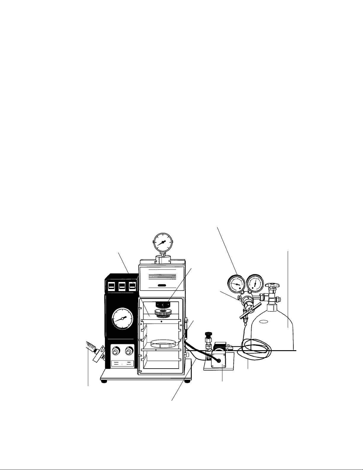
Fig. 1.1. Unit components, front view.
1
Helium
Pressure
Regulator
Vacuum (reinforced PVC)
Tygon Tubing
2.5 ft PEEK Tubing
6 ft PEEK Tubing
Tank of Pressurized Helium
(user provided)
Rupture Disk
Retaining Cap
3-Way Helium Metering
(solenoid) valve
Microcarrier Launch
Assembly
Helium Regulator
Target Plate Shelf
Page 5
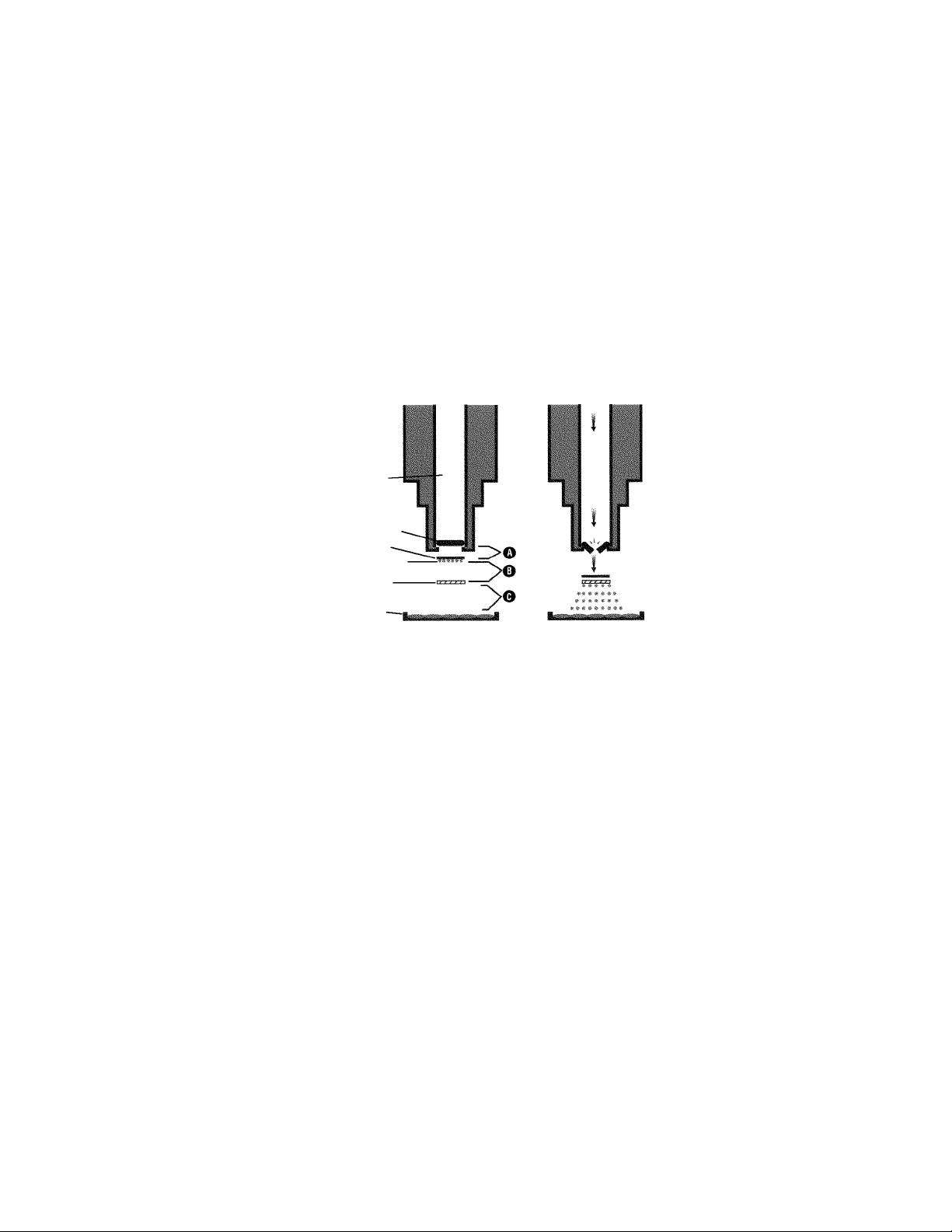
The Biolistic Process
The Biolistic PDS-1000/He system uses high pressure helium, released by a rupture disk,
and partial vacuum to propel a macrocarrier sheet loaded with millions of microscopic tungsten or gold microcarriers toward target cells at high velocity. The microcarriers are coated with
DNA or other biological material for transformation. The macrocarrier is halted after a short
distance by a stopping screen. The DNA-coated microcarriers continue traveling toward the
target to penetrate and transform the cells.
The launch velocity of microcarriers for each bombardment is dependent upon the helium pressure (rupture disk selection), the amount of vacuum in the bombardment chamber, the
distance from the rupture disk to the macrocarrier (A), the macrocarrier travel distance to the
stopping screen (B), and the distance between the stopping screen and target cells (C).
Fig. 1.2. The Biolistic bombardment process.
Design Improvements
The original Biolistic device used a gunpowder explosion to accelerate DNA-coated
microcarriers into target cells. The helium technology used in the current PDS-1000/He system has primary advantages of providing cleaner, safer, and more reproducible particle acceleration. This stems from the use of rupture disks that burst at a defined pressure. In addition,
helium inflicts less tissue damage. Bulletin 1689 offers a comparative analysis of gunpowder
and helium target patterns and transformation efficiencies.
The PDS-1000/He device was updated in March 1995 to improve the quality of key components. We removed parts originally designed to operate with the gunpowder acceleration
method. The most notable change was the conversion of the material used for the bombardment chamber from metal to a strong, lightweight plastic. This makes the instrument easier
to transport and clean, with no change in bombardment performance (identical internal chamber dimensions). An over-pressure relief valve and a particle filter on the vacuum vent supply were also added.
The actual steps for performing a particle bombardment of a biological sample are
unchanged, and the consumables are also the same with the plastic case version. Extensive testing involving the genetic transformation of yeast, plant, and animal cells by both Bio-Rad
and independent researchers demonstrated that the gene transfer results obtained with the
new plastic chamber design are equivalent to those of the previous metal chamber model.
See Appendix 8.2 for a description of parts unique to the metal-chamber design.
2
Before
Gas Acceleration Tube
Rupture Disk
Macrocarrier
Stopping Screen
Target Cells
DNA-coated Microcarriers
After
Page 6
1.3 Important Safety Information
Pressurized Helium Safety Information
Caution: Although helium is neither toxic nor flammable, all gases under pressure are potentially dangerous if used improperly. Never use a helium tank with, or attach a tank to, the
PDS-1000/He system unless the tank is properly secured. Follow the instructions provided with
the helium cylinder from the supplier and those that are applicable for your institution (site
safety officer). Bio-Rad has supplied tubing, fittings, a control valve, and a pressure regulator capable of safely handling the high pressure helium gas used in the Biolistic bombardment process. These components have been carefully selected and are the only parts to be
used with the PDS-1000/He system.
Power Safety Information
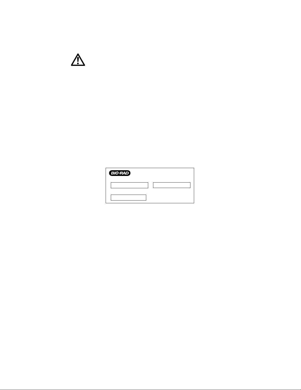
Figure 1.3 shows the serial number certification label which is found at the rear of the
Biolistic PDS-1000/He unit. This label provides the manufacturing data about the instrument,
its voltage settings, and CDRH standards for electrical safety. This instrument and its accessories conform to the IEC and CDRH standards for electrical safety.
Fig. 1.3. Instrument serial number label on the rear of the instrument.
1.4 Requirements for System Operation
Selecting Site for Operation
Prepare a space 61 cm wide x 46 cm long x 61 cm high (24 inches x 18 inches x 24 inches)
preferably in a bio-containment hood or other tissue preparation area, near a standard electrical
outlet (110 V/60 Hz in the U.S.). Also, allow for placement of the vacuum pump near the site of
operation if house vacuum is not used (see Vacuum Supply).
User Supplied Components
Helium Supply
Only helium gas is to be used with PDS-1000/He system. The low atomic weight of helium permits maximum gas expansion into the bombardment chamber. Thus, sufficient acceleration of the DNA-coated microcarriers is generated for penetration of the target cell membrane.
Obtain a high pressure (2,400 to 2,600 psi) tank of high purity helium for optimization of
bombardment conditions for the biological system of choice. This allows use of all of the rupture
disks (the highest disk has a 2,200 psi rating). Only grade 5 (99.999%) or grade 4.5 (99.995%)
helium is to be used, since helium of a lesser grade contains contaminating material which may
obstruct gas flow within the PDS-1000/He system, as well as contaminate the biological sample.
Follow all safety instructions provided by helium supplier for helium tank installation.
3
Made in U.S.A.
Model No.
Voltage
Serial No.
Page 7

The helium pressure regulator (supplied) has a CGA 580, female fitting (standard in the
United States) for attachment to the user-supplied helium tank. An adaptor to this fitting may
be required outside the United States. Contact your local Bio-Rad office for information on
the helium pressure regulator adaptor requirements in your location.
A user-supplied, 1 inch adjustable wrench is required for attachment of the regulator to
a helium tank having a capacity of 55 cubic feet or greater.
Vacuum Source
The main unit of the PDS-1000/He system must be connected to a vacuum source capable of evacuating the bombardment chamber to a minimum of 5 inches of mercury for operation. This minimum vacuum requirement is part of the instrument safety system (the chamber
door must be sealed for helium pressure to be delivered into the main unit). Tubing is supplied
to connect the PDS-1000/He system to vacuum source.
For maximum evacuation capacity, we recommend connecting the PDS-1000/He device
to an oil-filled, rotary vane vacuum pump, either single or dual stage, with an pumping speed
of 90–150 liters/minute (3–5 cubic feet/minute). This pumping rate minimizes the time target
cells are exposed to vacuum. Oil for the vacuum pump must be supplied by the user. An
exhaust mist eliminator on the vacuum pump is also recommended.
The level of the vacuum required in the bombardment chamber depends on the biological system being targeted for transformation. Higher vacuum reduces drag forces on microcarriers during helium-driven acceleration. During the brief bombardment process (less than
1 minute), typical protocols require a vacuum level within the bombardment chamber between
15–29 inches of mercury. Some cells, tissues, and intact plant cells require a high vacuum
(up to 28 inches of mercury) for efficient transformation.
House vacuum may be sufficient for bombardment of certain cell types (mammalian
cells), but house vacuum pumping rates can fluctuate and vary greatly in overall evacuation
capacity (typically 20 inches of mercury, maximum).
Consumables
The 500 Optimization Kit (catalog number 165-2278) provides the consumables needed
for 500 bombardments. It is recommended for users who have yet to determine the optimal
conditions for the bombardment of the biological system of interest. The kit contains 0.25 g
each of 0.6 µ, 1.0 µ, and 1.6 µ gold microcarriers, 100 each of the nine different rupture disks
(ranging from 450 psi to 2,200 psi), 500 macrocarriers, and 500 stopping screens. After optimal conditions are determined, Standard Pressure Kits are available (see Section 7 or the current Bio-Rad catalog for a complete listing).
Additional Laboratory Supplies and Equipment
Vortex mixer is needed for microcarrier preparation.
Common laboratory supplies, such as 95% ethanol, pipettes, etc. are required, as cited in
standard protocols.
Additional Items Available from Bio-Rad
The Yeast Optimization Kit (catalog number 170-3100) allows first-time users to become
familiar with the Biolistic instrument. It is also helpful for experienced users wishing to
periodically standardize their bombardment conditions. This kit provides all of the biological
material needed to transform yeast. Yeast provides a system that is quickly and easily assayed.
The kit demonstrates the effect of varying the DNA concentration, rupture disk pressure, and
the target distance (from the stopping screen), and includes Saccharomyces cerevisiae strain
4
Page 8
948, YEp352 DNA, CaCl2, spermidine, culture medium, and plating medium. Enough material for 60 bombardments is provided.
Macrocarrier Holders, set of 5 (catalog number 165-2322), are included with the Biolistic
PDS-1000/He system. Additional holders are desirable to facilitate a series of bombardments
in one experiment.
The Disk-Vac (catalog number 165-2323) is a small pen-shaped device capable of generating a suction for efficient handling of rupture disks and macrocarriers. Use of the Disc-Vac
reduces static generated during manipulation and prevents contamination with glove powder
or oil from skin.
Customers outside the continental USA and Canada will require a Voltage Converter
(catalog number 165-2259). To use the system, you must locally obtain a cord set which has
an IEC/320/CEE 22 connector on one end. This connects to the Voltage Converter and is the
type commonly found on computers or televisions. The other end of the power cord will
terminate in a plug which will fit the receptacle used in your location. Contact your local
Bio-Rad office for more information on this Voltage Converter.
Section 2
Product Description
2.1 Packing List
Check the items received with your PDS-1000/He unit against the list below. If items are
missing, contact your local Bio-Rad office.
Instruction Manual
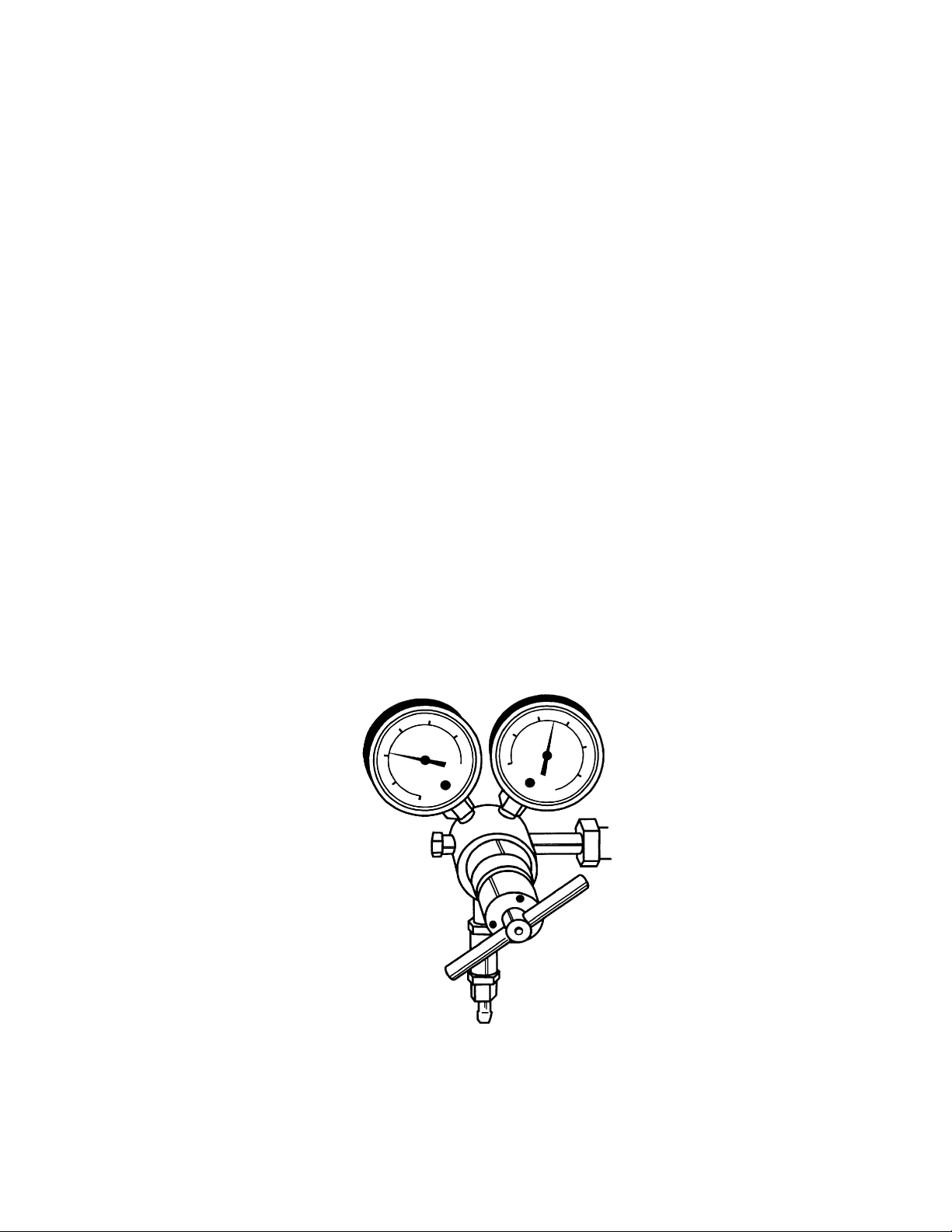
Pressure Regulator for Helium Cylinder (with in-line 0.45 µ filter)
Fig. 2.1. Helium pressure regulator.
5
Page 9
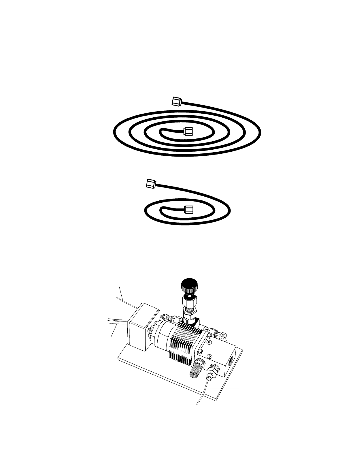
6.0 ft PEEK plastic tubing (1/16" OD x .010" ID tubing & fittings), used to connect 3-way
helium metering (solenoid) valve to helium pressure regulator
2.5 ft PEEK plastic tubing (1/16" OD x .010" ID tubing and fittings), used to connect
3-way helium metering (solenoid) valve to rear of main unit
Fig. 2.2. 6 ft and 2. 5 ft PEEK tubing.
3-Way Helium Metering (solenoid) Valve, with attached cord for power connection to
main unit
Power cord (US and Canada only, 120 V three prong plug)
Fig. 2.3. 3-way helium metering (solenoid) valve.
6
Power Cord
To Unit
6 ft PEEK Tubing
To Helium Tank
2.5 ft PEEK
Tubing To Unit
Page 10
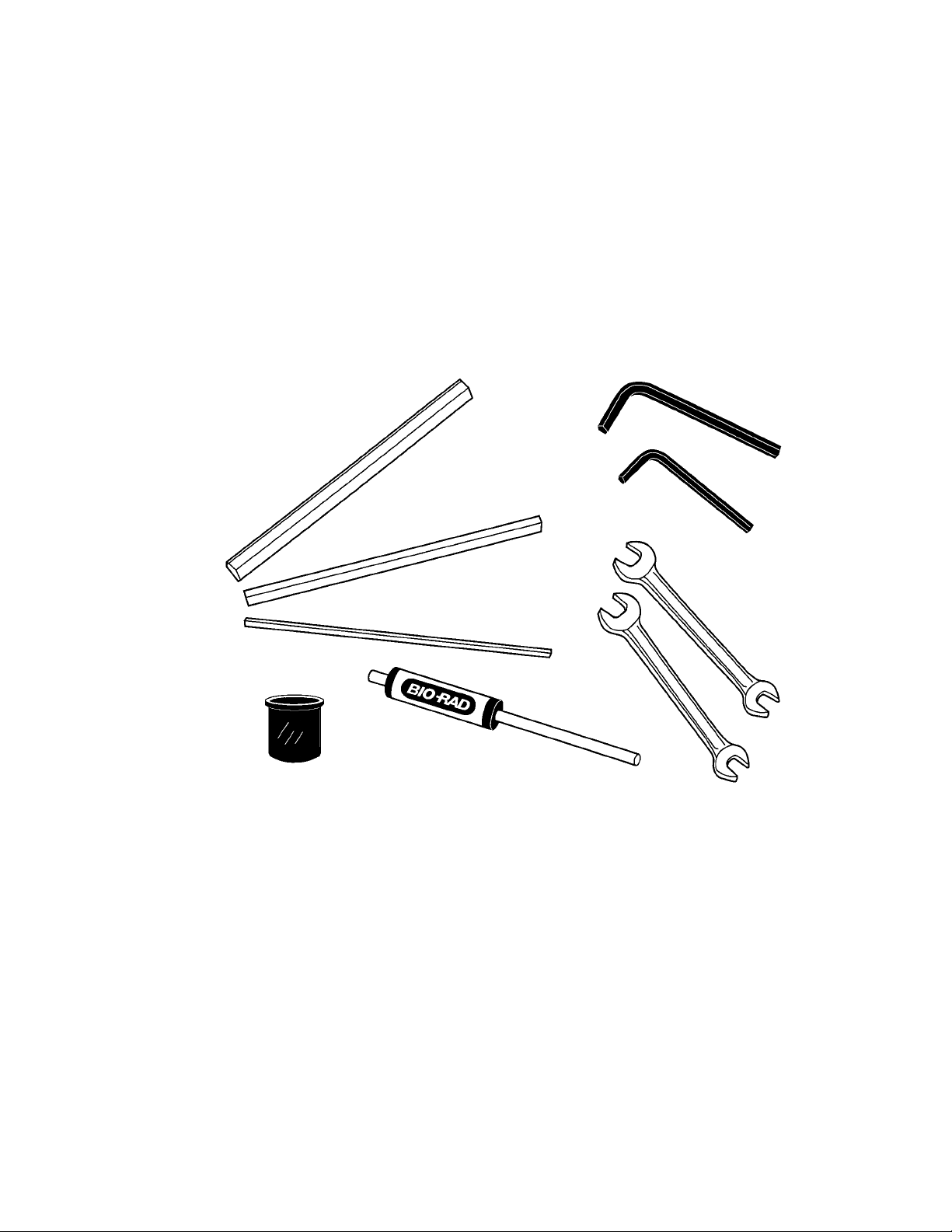
Tools
3 Hexagonal gap setting tools (1 each- 1/8", 1/4", and 3/8"), used to set gap between the
bottom of the rupture disk retaining cap and the lid of the microcarrier launch assembly
1 3/16" hex key (Allen) wrench, used for removal of gas acceleration tube (service only)
1 1/8" hex key (Allen) wrench, used for releasing set screw in microcarrier launch assembly shelf
2 1/4" x 5/16" open-end wrenches, used for connecting small Swagelock fittings of plastic
PEEK tubing to rear of instrument, external solenoid valve, and helium pressure regulator
1 torque wrench for rupture disk retaining cap
1 seating tool for macrocarriers
Fig. 2.4. PDS-1000/He tools.
7
Page 11
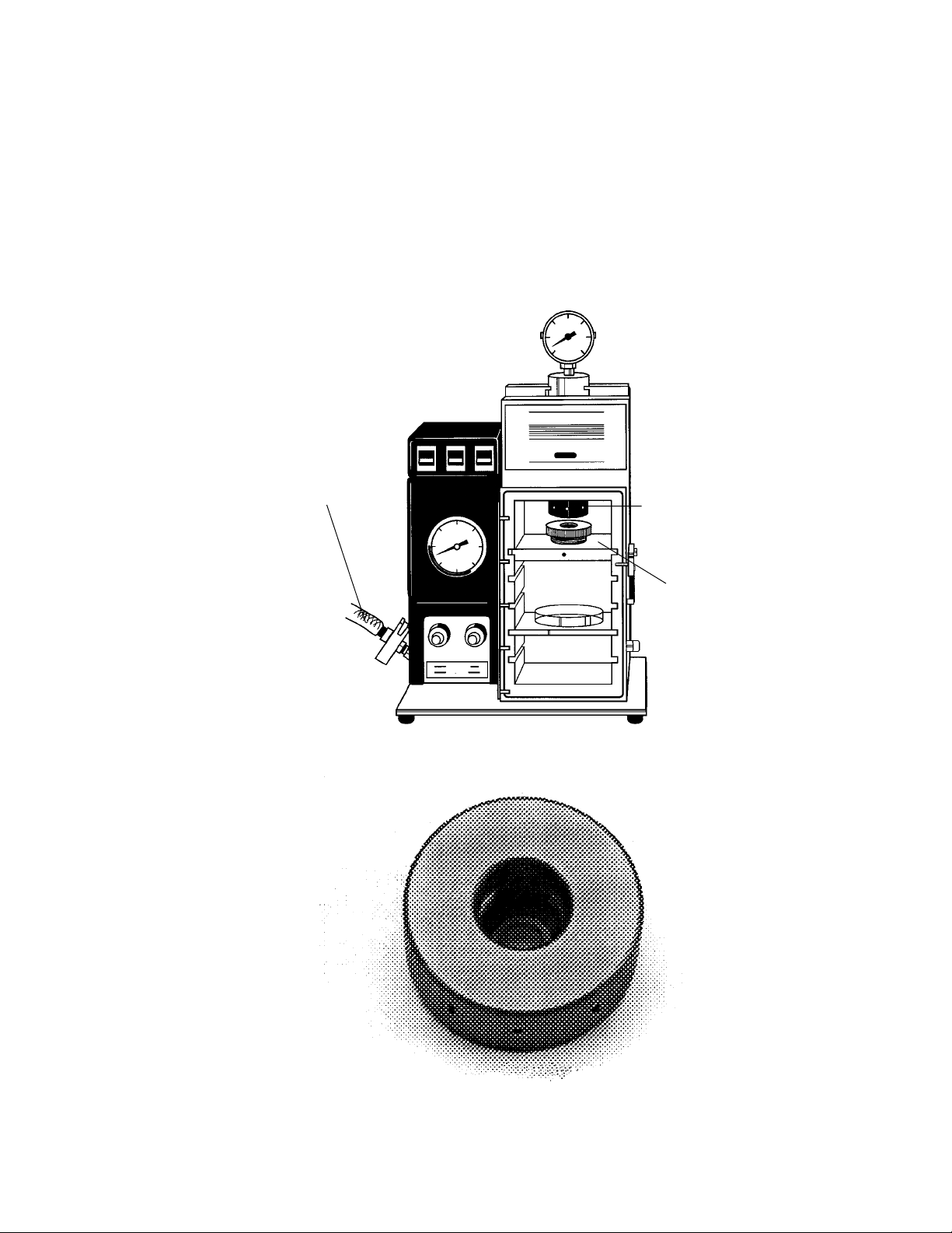
PDS-1000/He Main unit (bombardment chamber with control panel and gauges; shipped
fully assembled)
Reinforced PVC vacuum tubing (1/2" ID x 3/4" OD, 5 ft. length & fitting) attached to rear
of unit by clamp assembly (centering ring, vacuum hose clamping ring and nozzle adaptor; see Section 3.2 for individual components)
Rupture disk retaining cap (with torque wrench placement holes; Figure 10), attached to
gas acceleration tube within bombardment chamber
Fig. 2.5. PDS-1000/He main unit.
Fig. 2.6. Rupture disk retaining cap.
8
Microcarrier
Launch Assembly
Vacuum Tubing
Rupture Disk
Retaining Cap
Page 12
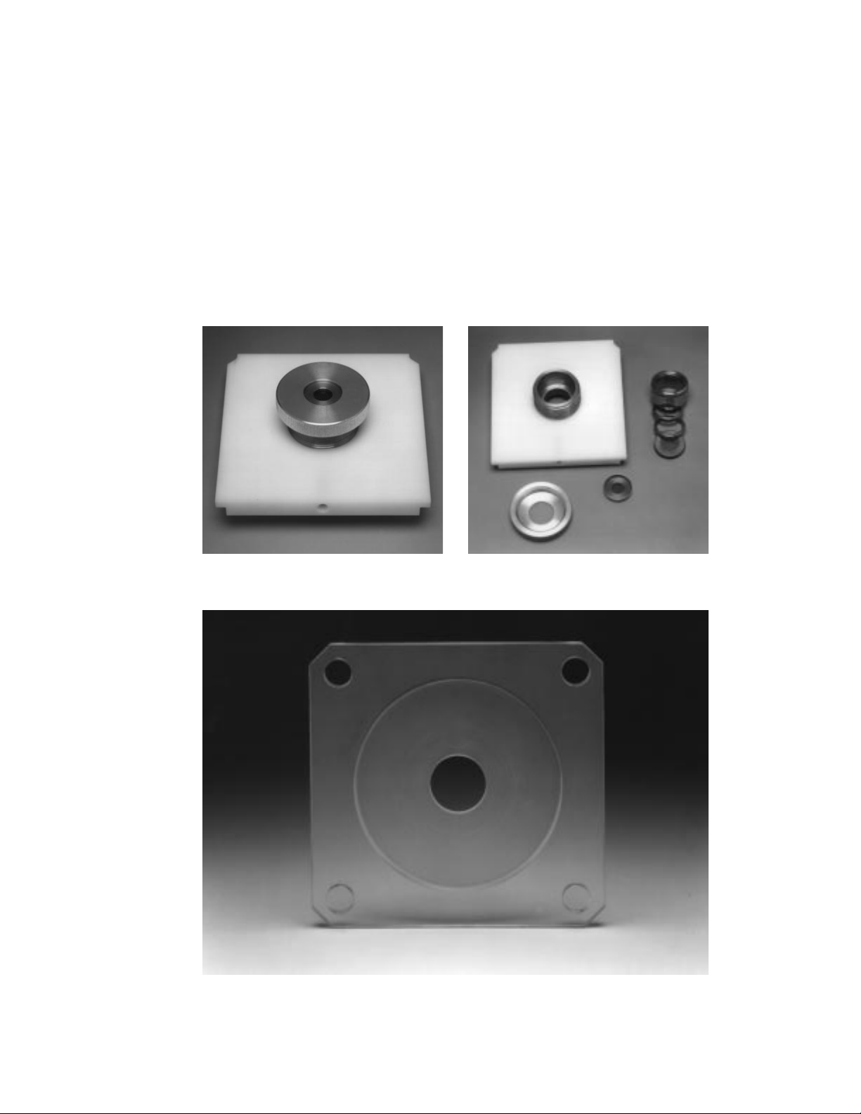
Microcarrier launch assembly (shipped fully assembled) consists of the following:
Launch Assembly Shelf with Recessed Set Screw
Macrocarrier Cover Lid
Adjustable Nest
Fixed Nest with Retaining Spring
Stopping screen Support Ring
Spacer Rings, 5 mm height, 2
Macrocarrier Holders, 5, for use within microcarrier launch assembly, after macrocarrier
is inserted using macrocarrier insertion tool
Target Plate Shelf
Fig. 2.7. Microcarrier launch assembly (A) and disassembled components (B).
Fig. 2.8. Target plate shelf.
9
A
B
Page 13

2.2 Identification of Unit Controls and Components
The following is a brief description of the operation controls for the PDS-1000/He unit
(Figure 2.9)
Table 2.1. Unit Controls and Components
Controls and
Components Description
Front View- Exterior
Power Switch, ON/OFF Controls supply of line electrical power to the
instrument.
Fire Switch Controls flow of helium into Gas Acceleration Tube by
activating Solenoid Valve. Illuminated red when
enabled, i.e. when safety interlock is satisfied that at
least 5 inches Hg. vacuum is present in chamber.
Fire Switch must be held ON continuously until
Rupture Disk bursts; then release Fire Switch to stop
flow of helium.
If the Fire Switch is released before the disk ruptures,
the helium is vented via a safety vent in the external
three-way metering (solenoid) valve.
Vac/Vent/Hold Switch Controls application of vacuum to bombardment
chamber. Vac applies vacuum from line source. Vent
releases vacuum using filtered air. Hold maintains
vacuum by isolating chamber.
Bombardments should be performed with this switch
in “Hold” position.
Vacuum Gauge Indicates level of vacuum in bombardment chamber,
in inches of mercury where zero equals ambient atmospheric pressure.
Vacuum/Vent Rate Regulate rate of application and relief of vacuum in
Control Valves bombardment chamber. Clockwise rotation closes valves.
Helium Pressure Gauge Indicates helium pressure in Gas Acceleration Tube,
in psi. When solenoid valve is activated by Fire Switch,
the needle in this oil-filled gauge rotates clockwise until
rupture disk bursts. Watch this gauge carefully during a
bombardment and note the actual rupture pressure.
Gas Acceleration Tube Helium accumulates within this tube when it is sealed
by rupture disk at chamber-end of Tube. Helium PEEK
tubing connects at top of Gas Acceleration Tube outside,
rear of chamber.
Bombardment Chamber Holds Rupture Disk, Microcarrier Launch Assembly, and
biological target under vacuum during a bombardment.
10
Page 14
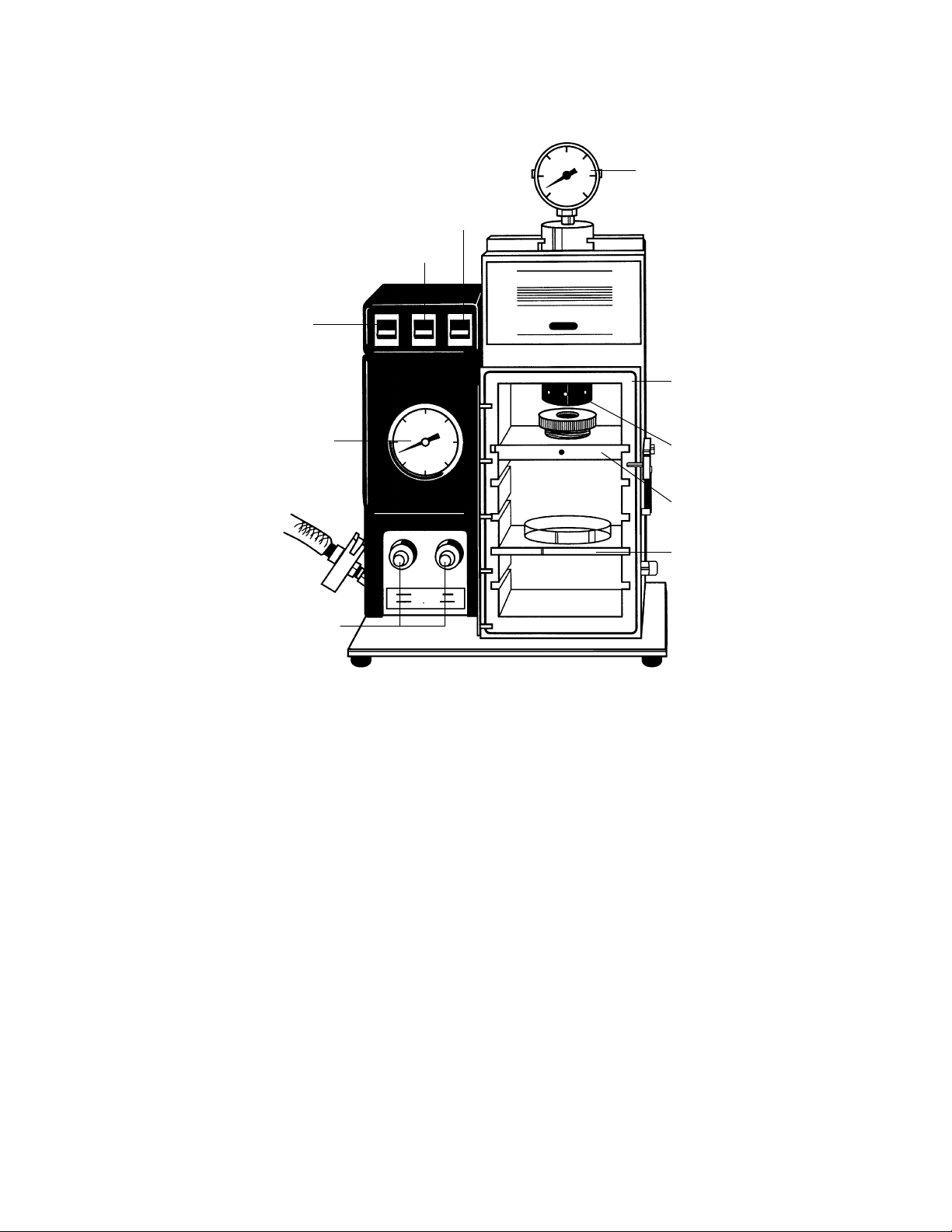
Fig. 2.9. Front view of PDS-1000/He unit.
Table 2.2. Front View-Interior of Bombardment Chamber
Bombardment Chamber Closes chamber with a solid piece of polycarbon-
Door (with Brace) ate plastic. Note the single, large o-ring which
seals vacuum in the chamber, and the self-positioning brace which eliminates flex of chamber
walls during bombardment cycle.
Rupture Disk Seals Rupture Disk against chamber end of Gas
Retaining Cap Acceleration Tube. This must be tightened securely.
The Torque Wrench is used in the holes in the cap
which are visible in the photo.
Microcarrier Launch Assembly Holds the DNA/microcarrier preparation on a
Macrocarrier sheet over the Stopping Screen in
the path of the helium shock wave.
Target Shelf Holds the biological target in a Petri plate in the
path of the accelerated DNA/microcarrier preparation. Particle flight distance is determined by positioning the shelf at one of four levels using slots in
the chamber walls.
11
Microcarrier
Launch Assembly
Power Switch
ON/OFF
Helium Pressure Gauge
Target Shelf
Bombardment
Chamber Door
Vacuum Gauge
Vac/Vent/Hold Switch
Vacuum/Vent Rate
Control Valves
Fire Switch
Disk Retaining
Cap
Page 15
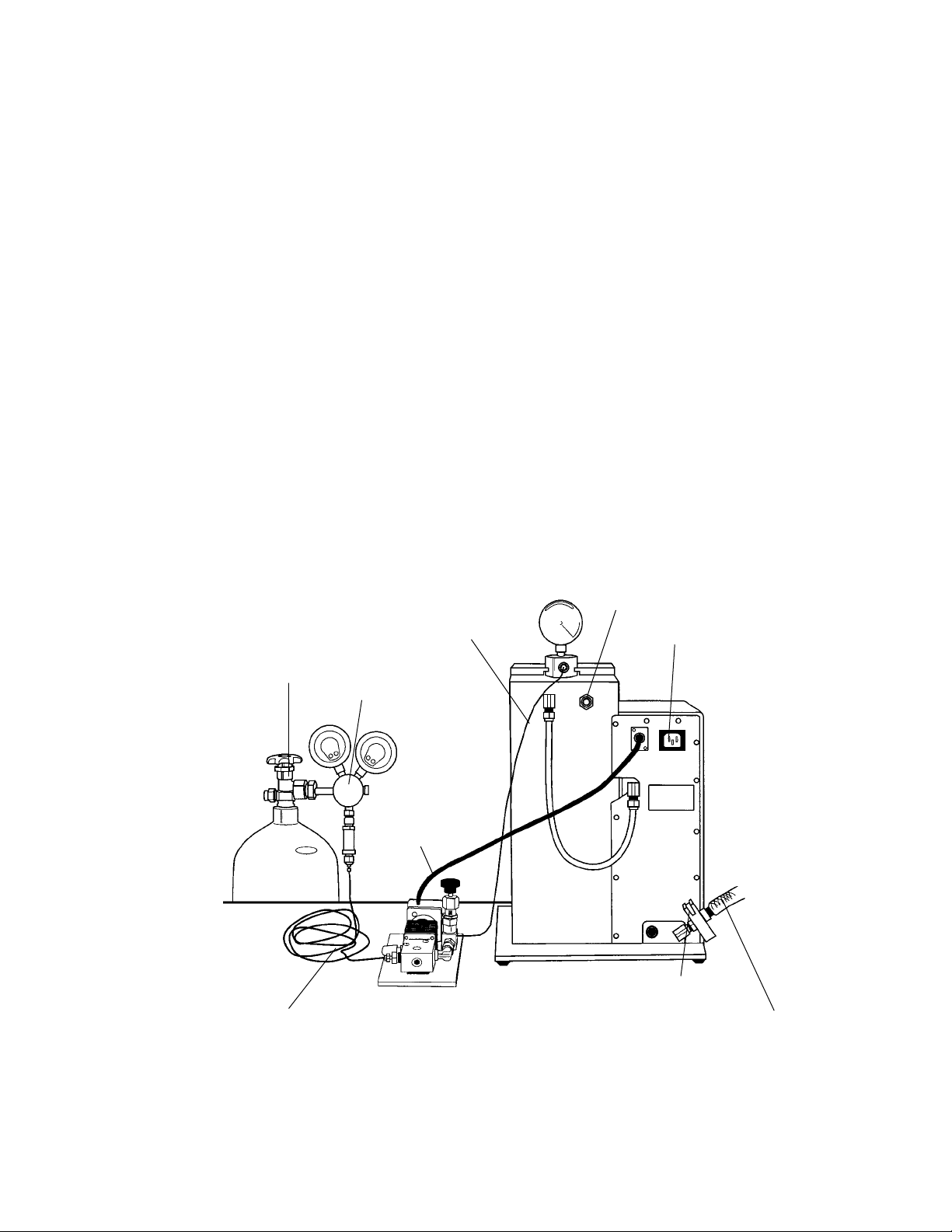
Table 2.3. Rear Connections
Refer to Figure 2.10 for a rear perspective view of the unit.
Helium Connection to Gas Tube Connects top of Gas Acceleration Tube to plastic
tubing from Solenoid Valve, supplying high pressure helium.
Over-Pressure Relief Valve Opens at 0.5 psi chamber pressure to relieve
accumulation of gas. A new safety feature.
Automatically resets after activation.
Vacuum Line, Chamber to Controls Supplies vacuum to chamber from control valves.
Helium Metering (Solenoid) Valve Supplies electric power to 3-way Solenoid Valve
Electrical Connection in helium line. Plug the three-pin connector from
the Solenoid Valve into this receptacle.
Line Cord Electrical Connection Supplies electric power to Biolistic unit from
house line. Plug connector from Line Cord into
this receptacle.
Vacuum Line, Connection to Source Connects unit to house vacuum supply or vacuum
pump via fittings included. Feeds into vacuum
flow controls.
Fig. 2.10. Rear view of main unit, component connection points.
12
Vacuum Port / Clamping Ring
Attachment Site
6.0 ft. PEEK Tubing
(connects to helium regulator)
2.5 ft PEEK Tubing
(connects to gas
acceleration tube)
Metering (solenoid)
Valve Power Cord
(connects to rear
of main unit)
Helium Pressure
Regulator
Adjustable
Metering Valve
Main Unit Power
Cord Socket
Over-Pressure Relief Valve
Vacuum (reinforced PVC)
Tygon®Tubing
Page 16
Section 3
Installation
3.1 Connecting the PDS-1000/He System to a Helium Source
Refer to Section 2.2, Identification of Unit Controls and Components, prior to system
installation.
Helium Pressure Regulator Installation
Connecting the helium pressure regulator to a tank of pressurized helium.
Components needed:
• Pressure regulator for helium cylinder (with 0.45 micron in-line filter), provided with
unit (Figure 3.1).
• Cylinder of grade 4.5 to 5.0 helium (minimum 99.995% pure); maximum pressure of
2,600 psi, user supplied.
• 1 1/8" open-end wrench or a 10" or 12" adjustable wrench, user supplied.
Note: The regulator is intended for use only with helium gas under a maximum of 2,600 psi
of pressure. The outlet on pressurized helium cylinders used in the United States (maximum 2,600 psi) is compatible with the fitting supplied on the pressure regulator with the
PDS-1000/He unit (CGA 580, female fitting). Outside of the US, contact your local Bio-Rad
office for information regarding the proper cylinder/regulator fitting in your area.
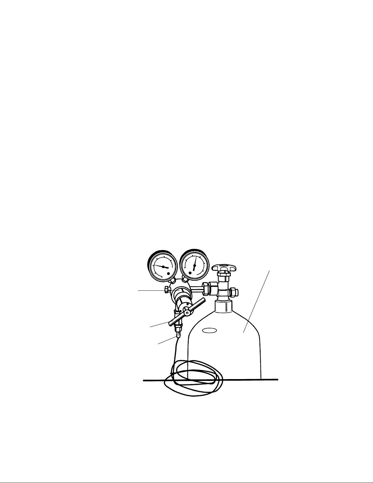
Fig. 3.1. Helium regulator/tank attachment.
13
Helium Tank
Adjustment Handle
Attachment Site for
6 ft PEEK Tubing
Helium Regulator
Page 17

1. Secure the cylinder to a wall, post, or other anchored fixture so it will not tip or fall during use.
2. Inspect the cylinder valve for dirt, dust, oil, grease, or damaged threads. Remove dust
and dirt with a clean cloth. Do not attach the regulator if you determine that the valve
port is damaged or cannot be cleaned. Inform your gas supplier of this condition and
request a replacement cylinder.
3. Clear the valve port of any foreign matter by standing to the side of the cylinder and
quickly opening and closing the cylinder valve.
4. Attach the regulator to the cylinder valve and tighten securely with a 1 1/8" open-end
wrench or a 10" or 12" adjustable wrench.
Three-Way Metering Valve (Solenoid) Installation
Connecting the helium pressure regulator to the 3-way helium metering (solenoid) valve
Components needed:
• Two 5/16" open end wrenches (Figure 2.4)
• PEEK tubing, 6 feet (Figure 2.2)
• Solenoid valve (Figure 2.3)
Note: The Swagelock fittings used on the flexible tubing are easily damaged by over
tightening. Turn finger-tight, then use wrench for 1/6 additional turn (60°).
1. Connect one end of the 6 foot tubing assembly to helium pressure regulator (Figure 3.1).
Attach the tubing to the in-line, 0.45 micron filter at the end of the regulator. Use two
5/16" open end wrenches to tighten the connection.
2. Connect the other end of the 6 foot tubing assembly to the inlet port of the 3-way helium
(solenoid) valve assembly. This is the port nearest the metal exhaust filter on the 3-way metering valve. Use two 5/16" open end wrench to tighten the connection (Figures 2.3 and 2.10).
Connecting the 3-way helium metering (solenoid) valve to the PDS-1000/He main unit
Components needed:
• Two 5/16" open end wrenches (Figure 2.4)
• PEEK tubing, 2.5 feet (Figure 2.2)
• Solenoid valve (Figure 2.3)
Note: The Swagelock fittings used on the flexible tubing are easily damaged by over
tightening. Turn finger-tight, then use the wrench for 1/6 additional turn (60°).
1. Connect one end of the 2.5 foot PEEK tubing assembly to the outlet port of the 3-way helium metering (solenoid) valve assembly (Figures 2.3 and 2.10). This is the port nearest the
adjustable metering valve (black knob). Use two 5/16" open end wrenches to tighten the
connection. Do not alter the setting of the metering valve at this time.
2. Connect one end of the 2.5 foot long PEEK tubing assembly to the PDS-1000/He unit.
This port is located on the gas acceleration tube, below the helium pressure gauge (top,
rear of unit). Use a 5/16" open end wrench to tighten the connection (Figure 2.10).
3. Plug the power cord of the 3-way helium metering (solenoid) valve into the rear of the
PDS-1000/He unit (Figure 2.10).
14
Page 18

3.2 Connecting the PDS-1000/He Unit to a Vacuum Source
The main unit is shipped with the vacuum hose assembly attached to the port on the rear
of the unit, via the clamping assembly. Only the connection of the free end of the tubing to a
vacuum source is required for connecting the vacuum source to the system.
Choice of Vacuum Source
A vacuum system with a 3 cfm (cubic feet per minute) or 100 l/min pumping capacity is rec-
ommended for use with the PDS-1000/He unit. This minimizes the total time the target cells/tissue are exposed to reduced atmospheric pressure when inside the bombardment chamber. It is
also recommended that the pump have an exhaust mist eliminator.
House or shared source vacuum systems commonly have variable evacuation capacities,
from 20 inches to 23 inches Hg. When multiple users access a common vacuum system, the
actual vacuum pressure will vary, often decreasing to less than 20 inches Hg. per outlet. This
is an inadequate vacuum level for yeast and plant cell/tissue bombardment.
Most rotary vacuum pumps will achieve up to 26–28 inches of mercury (Hg) vacuum.
However, the length of time required to attain the desired vacuum depends on the pumping
capacity of the vacuum source. The higher the pumping capacity, the less time is required to
achieve the desired vacuum. Variation in evacuation time in the bombardment chamber has
an unknown effect on target cells and tissue transformation efficiency.
Table 3.2. Pumping rates of various vacuum systems with the
PDS-1000/He system
Vacuum Source Vacuum Level
Pumping Capacity (inches of Hg) Evacuation Time
†
House/Common Source 20 10–15 seconds
29 Typically not attainable
Pump - 1 cfm or 28 l/min 20 12 seconds
29 45 seconds
Pump - 3 cfm or 100 l/min 20 7 seconds
29 25 seconds
†
Vacuum Flow Rate Valve fully open.
Replacement and Re-assembly of connecting components
See Figure 3.2 for a diagram outlining component assembly. The clamp consists of an O-
ring and a vacuum hose centering ring with male nozzle fitting screwed to it.
1. Place the clamping assembly at one end of the vacuum tubing. The vacuum tubing is
PVC-reinforced Tygon tubing (1/2" ID x 3/4" OD; 5 feet length).
2. The vacuum tubing is shipped with the clamping ring assembly (Figure 3.2) attached to
the PDS-1000/He unit at the brass vacuum port located on the rear of the unit.
3. Attach the free end of the vacuum hose assembly to the vacuum source.
15
Page 19

Fig. 3.2. Components used to connect vacuum source to main unit.
3.3 Power Cord / Voltage Regulator
The power cord must be plugged directly into a 100 V-120 V outlet. Plug other end into
unit. For use with a 220 V or 240 V line voltage (users outside the US or Canada), connect a
voltage converter to the power cord prior to use (catalog number 165-2259, see Figure 3.3).
You must supply a cord set that has an IEC-320/CEE-22 connector on the end that attaches
to the voltage converter; the other end of the cord set will terminate with a plug that is compatible with the electrical outlets in your area.
Fig. 3.3. Voltage converter.
16
Clamping Ring
Centering Ring
Vacuum tubing
Male Pipe Adaptor
Quick Flange
Adaptor
Page 20

Section 4
Operation of the PDS-1000/He Instrument
4.1 Preparation of System Components Prior to Bombardment
Instrument Preparation
1. Verify that helium tank has 200 psi in excess of desired rupture disk pressure for bombardment.
2. Set gap distance between rupture disk retaining cap and microcarrier launch assembly.
When the rupture disk retaining cap is in place, insert the fully assembled microcarrier
launch assembly (with cover lid) inside the bombardment chamber on the highest possible bombardment chamber wall slot (Figure 4.1). The set screw in the white plastic shelf
should face outward. Release the set screw on the front of the microcarrier launch assembly with the smaller of the two hex key wrenches provided (Figure 2.4).
Fig. 4.1. Microcarrier launch assembly and target shelf inside bombardment chamber.
17
Page 21

Three hexagonal gap adjustment tools of 1/8", 1/4", and 3/8" have been provided to reproducibly set the gap distance (Figure 2.4). A 1/4" distance between the rupture disk retaining cap and the macrocarrier cover lid is recommended for initial optimization
bombardments.
While holding the hexagonal gap adjustment tool against the bottom of the rupture disk
retaining cap, turn the adjustable nest until the macrocarrier cover lid touches the gap
adjustment tool. The position of the adjustable nest is fixed by tightening the set screw in
the white plastic shelf with the hex key wrench.
Fig. 4.2. Microcarrier Launch Assembly adjustment.
18
Brass Adjustable Nest
Stainless Steel Fixed Nest
Spacer Rings
Stopping Screen Support
Macrocarrier Holder
Macrocarrier Cover Lid
Page 22

3. Prepare the Rupture Disk Retaining Cap. After setting the gap between cap and microcarrier launch assembly, wrap the Rupture Disk Retaining Cap in aluminum foil and sterilize by autoclaving.
4. Prepare the Microcarrier Launch Assembly.
The effect of the gas shock wave on the microcarrier velocities is determined in part by
the gap between the rupture disk and the macrocarrier.
The macrocarrier flight distance can be adjusted by varying the positions of the stopping
screen support and the spacer rings inside the fixed nest (Figure 4.2). The Stopping Screen
Support is placed in the middle position at the factory. This is the recommended position
when initially optimizing bombardment parameters.
To make this adjustment, remove the microcarrier launch assembly from the PDS-1000/He
unit. Unscrew and remove the macrocarrier cover lid. Disassemble the components of the
microcarrier launch assembly by placing the macrocarrier insertion tool into the bottom of
the assembly and pushing up. This releases the stainless steel fixed nest from the brass
adjustable nest. The two spacer rings and the stopping screen support will fall out from
within the fixed nest.
To change the factory-set position to the position for the minimum macrocarrier travel distance (6 mm), invert the fixed nest and insert the stopping screen support inside the fixed
nest so that the conical side of the stopping screen support faces down in the final orientation; then insert the two spacer rings (5 mm thickness, each). With the fixed nest still
inverted, place the macrocarrier launch assembly over the fixed nest and seat the fixed nest
within the brass adjustable nest.
If greater macrocarrier travel is desired, rearrange the spacer rings and stopping screen support accordingly. The macrocarrier travel distance can be increased in two 5 mm steps, to
a maximum of 16 mm.
Sterilize the microcarrier launch assembly by wrapping in aluminum foil and autoclaving.
Alternatively, this assembly can be sterilized by wiping with 70% ethanol, followed by
drying in a sterile environment.
5. Target Shelf
Sterilize the target shelf by wiping with 70% ethanol, followed by drying in a sterile environment just prior to use. This part may not be autoclaved.
19
Page 23

Consumable Preparation
Several consumables are available for use with the PDS-1000/He system (Figure 4.3).
Fig. 4.3. Consumables for the PDS-1000/He instrument. The 0.6 micron gold is not pictured.
1. Macrocarriers
Pre-assemble and pre-sterilize the macrocarrier set in a macrocarrier holder prior to performing sample cell/tissue bombardments. The Disk-Vac (catalog number 165-2323)
provides ease in handling rupture disks and macrocarriers.
Macrocarriers are shipped in quantities of 500/box, with paper linings between disks.
Transfer selected macrocarriers to individual Petri dishes for easier handling. Remove
the paper lining from between the macrocarriers. Place the macrocarrier into the macrocarrier holder using the seating tool (Figure 4.4). The edge of the macrocarrier should be
securely inserted under the lip of the macrocarrier holder. The macrocarrier holders, with
macrocarriers already in place, should be sterilized by autoclaving.
2. Rupture disks
Rupture disks (Figure 4.3) are packaged and shipped in quantities of 100/box. Transfer
selected rupture disks to individual Petri dishes for easier handling. Sterilize rupture disks
by briefly dipping them in 70% isopropanol just prior to insertion in the Retaining Cap.
Do not soak for more than a few seconds. Extensive soaking may delaminate the disks,
resulting in premature rupture. All disks, with the exception of those rated at 450, 650, and
1,100 psi, are laminated. Autoclaving is not recommended because of potential delamination.
20
A. Macrocarriers
B. Rupture disks
C. Stopping screens
D. Tungsten microcarriers
E. Gold microcarriers
A
C
D
E
B
Page 24

Fig. 4.4A and 4.4B. Insertion of macrocarrier into macrocarrier holder with plastic insertion tool.
3. Stopping screens
Transfer selected stopping screens (Figure 4.3) to individual Petri dishes for easier handling. Sterilization by autoclaving is recommended. Alternatively, these parts can be sterilized by soaking in 70% ethanol, followed by drying in a sterile environment.
4. Microcarriers
The following procedure prepares tungsten or gold microcarriers for 120 bombardments
using 500 µg of the microcarrier per bombardment, based on the method of Sanford, et
al. [Methods in Enzymology, 217, 482-509 (1993)].
Weigh out 30 mg of microparticles into a 1.5 ml microfuge tube.
Add 1 ml of 70% ethanol (v/v).
Vortex vigorously for 3–5 minutes (a platform vortexer is useful).
Allow the particles to soak in 70% ethanol for 15 minutes.
Pellet the microparticles by spinning for 5 seconds in a microfuge.
Remove and discard the supernatant.
Repeat the following wash steps three times:
• Add 1 ml of sterile water.
• Vortex vigorously for 1 minute.
• Allow the particles to settle for 1 minute.
• Pellet the microparticles by briefly spinning in a microfuge.
• Remove the liquid and discard.
After the third wash, add 500 µl sterile 50% glycerol to bring the microparticle concentration to 60 mg/ml (assume no loss during preparation).
The microparticles can be stored at room temperature for up to two weeks. Tungsten aliquots
should be stored at -20 °C to prevent oxidation. Gold aliquots can be stored at 4 °C or room
temperature.
Store dry tungsten and gold microcarriers in a dry, non-oxidizing environment to minimize agglomeration.
21
Macrocarrier
Insertion
Tool
Helium
Macrocarrier
Helium
Macrocarrier
Holder
Direction of Tool
Movement
Page 25

Coating Washed Microcarriers with DNA
The following procedure is sufficient for six bombardments; if fewer bombardments are
needed, adjust the quantities accordingly.
Vortex the microcarriers prepared in 50% glycerol (30 mg/ml) for 5 minutes on a platform
vortexer to resuspend and disrupt agglomerated particles.
When removing aliquots of microcarriers, it is important to continuously vortex the tube
containing the microcarriers to maximize uniform sampling. When pipetting aliquots, hold the
microcentrifuge tube firmly at the top while continually vortexing the base of the tube.
Remove 50 µl (3 mg) of microcarriers to a 1.5 ml microcentrifuge tube.
Continuous agitation of the microcarriers is needed for uniform DNA precipitation onto
microcarriers. For added convenience and/or multiple samples, use a platform attachment on
your vortex mixer for holding microcentrifuge tubes.
While vortexing vigorously, add in order:
• 5 µl DNA (1 µg/µl)
• 50 µl 2.5 M CaCl
2
• 20 µl 0.1 M spermidine (free base, tissue culture grade)
Continue vortexing for 2–3 minutes.
Allow the microcarriers to settle for 1 minute.
Pellet microcarriers by spinning for 2 seconds in a microfuge.
Remove the liquid and discard.
Add 140 µl of 70% ethanol (HPLC or spectrophotometric grade).
Remove the liquid and discard.
Add 140 µl of 100% ethanol.
Remove the liquid and discard.
Add 48 µl of 100% ethanol.
Gently resuspend the pellet by tapping the side of the tube several times, and then by vor-
texing at low speed for 2–3 seconds.
4.2 Performing a Bombardment
Quick Guide (This summary is repeated in Section 8.4 as a tear-out sheet.)
Before the Bombardment
1. Select/adjust bombardment parameters for gap distance between rupture disk retaining cap
and microcarrier launch assembly. Placement of stopping screen support in proper position inside fixed nest of microcarrier launch assembly
2. Check helium supply (200 psi in excess of desired rupture pressure).
3. Clean/sterilize:
Equipment: rupture disk retaining cap, microcarrier launch assembly
Consumables: macrocarriers/macrocarrier holders
4. Wash microcarriers and resuspend in 50% glycerol
5. Coat microcarriers with DNA and load onto sterile macrocarrier/macrocarrier holder the
day of experiment
22
Page 26

Firing the Device
1. Plug in power cord from main unit to electrical outlet.
2. Power ON.
3. Sterilize chamber walls with 70% ethanol.
4. Load sterile rupture disk into sterile retaining cap.
5. Secure retaining cap to end of gas acceleration tube (inside, top of bombardment chamber) and tighten with torque wrench.
6. Load macrocarrier and stopping screen into microcarrier launch assembly.
7. Place microcarrier launch assembly and target cells in chamber and close door.
8. Evacuate chamber, hold vacuum at desired level (minimum 5 inches of mercury).
9. Bombard sample: Fire button continuously depressed until rupture disk bursts and helium pressure gauge drops to zero.
10. Release Fire button.
After the Bombardment
1. Release vacuum from chamber.
2. Target cells removed from chamber.
3. Unload macrocarrier and stopping screen from microcarrier launch assembly.
4. Unload spent rupture disk.
5. Remove helium pressure from the system (after all experiments completed for the day).
Detailed Operation Procedure
Note: We recommend that the first bombardment each day be a “dry run” with no target
cells or microcarriers to ensure that the system is set up properly and the gas pathway is
filled with helium, not air.
1. Power On
With the unit plugged in to the appropriate electrical outlet or voltage converter, turn on the
unit by pressing the ON switch. This is the left-most red control panel switch (Figure 2.9).
2. Helium Pressure
Confirm that the helium tank pressure regulator is set to 200 psi over the selected rupture disk
burst pressure (e.g., set the regulator to 1,100 psi when working with a 900 psi rupture disk).
3. Pressurizing the System with Helium
Make certain that the helium pressure regulator is properly installed on the helium tank
(see Set-up).
Close the helium pressure regulator by turning the regulator adjustment screw counterclockwise until the adjusting spring pressure is released.
Release helium into the pressure regulator by carefully and slowly opening the cylinder
valve on the helium tank. The cylinder pressure in the tank is indicated on the high pressure gauge (the gauge closest to cylinder).
Set the desired helium delivery pressure for the rupture disk you are using (measured on
gauge on the outside, farthest from cylinder) by turning the regulator adjustment handle
clockwise. The pressure should be set to 200 psi above the rupture disk rating.
23
Page 27

4. Coating microcarriers with DNA
The day of the scheduled bombardment, coat the microcarriers with DNA. To obtain the
best results, use the DNA-coated microcarriers as soon as possible.
5. Loading DNA-coated microcarriers onto a macrocarrier/macrocarrier holder
Each macrocarrier is placed inside a macrocarrier holder and sterilized, as described
above. Prior to the application of the DNA-coated microcarriers onto a macrocarrier, prepare a small desiccating chamber for each macrocarrier/macrocarrier holder and place
away from excessive vibration.
A small desiccating chamber consists of a sterile 60 mm tissue culture Petri dish (with lid)
containing CaCl2as desiccant in the base of the dish (Figures 4.5 and 4.6). The desiccant is
covered with a small piece of filter paper to provide a stable platform for the macrocarrier/
macrocarrier holder. The sterile macrocarrier/macrocarrier holder is placed atop the filter
paper, with the macrocarrier facing up and the stainless steel holder touching the filter paper.
Fig. 4.5A and 4.5B. Loading DNA-coated microcarriers onto a macrocarrier/macrocarrier holder,
positioned in small desiccating chamber.
This environment permits rapid access to each macrocarrier and provides a low humidi-
ty environment for the ethanol to uniformly evaporate from the microcarriers. This low humidity, along with a minimum of vibration during evaporation, minimizes microcarrier
agglomeration.
For each macrocarrier, remove 6 µl aliquots (approximately 500 µg) of microcarriers and
spread evenly over the central 1 cm of the macrocarrier using a pipette tip. Pipet from a continuously vortexed tube and rapidly apply suspended microcarriers to the macrocarrier, as
microcarriers quickly settle out from the ethanol solution in the tube or even in the pipette tip.
Immediately cover the culture dish after application of the microcarrier suspension to the
macrocarrier. The ethanol should evaporate within 10 minutes to leave the DNA-coated microcarriers adhering to the macrocarrier. The loaded macrocarriers should be used within 2 hours.
6. Cleaning chamber walls
Clean the chamber of the PDS-1000/He as desired with 70% ethanol. Allow time for drying. Do not autoclave or flame sterilize the PDS-1000/He unit.
24
A
B
Page 28

7. Loading the rupture disk
Unscrew the rupture disk retaining cap from the gas acceleration tube from within the
bombardment chamber (Figure 4.6) or unwrap cap from sterile wrapping.
Fig. 4.6. Removal/mounting of rupture disk retaining cap onto end of gas acceleration tube inside
bombardment chamber.
Select rupture disk of desired burst pressure. Handle all rupture disks with sterile forceps
or Disk-Vac (catalog number 165-2323). Grease, fingerprints, or even powder from plastic
gloves on the rupture disk may prevent a tight seal from forming within the retaining cap.
Fig. 4.7. Rupture disk insertion into recess of retaining cap.
Immediately before placing a rupture disk in the retaining cap, briefly wet the rupture
disk in isopropanol (do not soak the disk for an extended period of time or the disk may
delaminate). Loading the rupture disk while wet forms a liquid gasket when the cap is screwed
onto the gas acceleration tube, and thereby reduces the failure rate of the rupture disk. Place
the rupture disk in the recess of the rupture disk retaining cap (Figure 4.7).
25
Page 29

Screw the rupture disk retaining cap onto the gas acceleration tube using a left -to-right
motion. Never tighten the rupture disk retaining cap without a rupture disk in place or scratching and deformation of the two metal surfaces will occur and cause helium to leak when a rupture disk is pressurized.
The retaining cap is tightened to a torque of 60 inch/pounds with the retaining cap torque
wrench. To use the torque wrench, insert the short end of the metal rod into an accessible hole
in the retaining cap. Push the long end of the rod to the right only until it touches the inner surface of the black tube (Figure 4.8). If the retaining cap is not tightened sufficiently, the rupture
disk may slip out of place as the gas acceleration tube fills with helium. Test fire once to fill gas
tubing with helium.
Fig. 4.8. Proper torque applied to retaining cap with torque wrench.
8. Microcarrier Launch Assembly
Unscrew the macrocarrier cover lid from the assembly. Place a sterile stopping screen on the
stopping screen support (Figure 4.9). Note: Never operate the PDS-1000/He instrument without
a stopping screen in place. The target sample will be destroyed from the uninterrupted acceleration
of the macrocarrier by the helium shock wave.
Install the macrocarrier/macrocarrier holder on the top rim of the fixed nest (Figure 4.10).
The dried microcarriers should be facing down, toward the stopping screen. Replace the
macrocarrier cover lid on the assembly and turn clockwise until snug. Do not over-tighten.
Place the microcarrier launch assembly in the top slot inside the bombardment chamber
(Figures 4.11 and 5.1).
26
➡
➥
Page 30

Fig. 4.9. Placement of stopping screen inside fixed nest with macrocarrier and cover lid removed.
Fig. 4.10. Removal / replacement of macrocarrier cover lid with assembled fixed nest.
Macrocarrier holder (with macrocarrier properly inserted) is inverted and placed atop fixed nest.
27
Page 31

9. Target cells/tissue placement in chamber
Place the Target Shelf at the desired level inside the bombardment chamber. Place the
sample (usually contained within a Petri dish) on the Target Shelf. Close and latch the sample chamber door.
10. Chamber evacuation/hold
Turn on the vacuum source. Set the vacuum switch on the PDS-1000/He (middle red
control switch, Figure 4.11) to the VAC position. Evacuate the sample chamber to the
desired level, at least 5 inches of mercury. The rightmost red control switch (the FIRE
switch) will be illuminated when the minimum vacuum is achieved.
When the desired vacuum level is reached, hold the chamber vacuum at that level by
quickly pressing the vacuum control switch through the middle VENT position to the
bottom HOLD position.
Fig. 4.11. Sample bombardment: power switch ON, vacuum switch on HOLD position, and user
continuously pressing FIRE button.
11. Bombard the sample
With the vacuum level in the bombardment chamber stabilized, press and hold the FIRE
switch to allow helium pressure to build inside the gas acceleration tube that is sealed by
a selected rupture disk (Figure 4.11).
28
Page 32

Estimate rupture disk burst pressure by observing the helium pressure gauge at the top of
the acceleration tube. A small pop will be heard when the rupture disk bursts. The rupture
disk should burst within 10% of the indicated rupture pressure and within 11–13 seconds.
Release the FIRE switch immediately after the disk ruptures to avoid wasting helium.
Releasing the FIRE switch prior to disk rupture will vent the gas acceleration tube via the
3-way helium metering (solenoid) valve.
Note: Variation in the burst pressure indicated on the helium pressure gauge (on the top
of the unit) from the rated rupture disk pressure may observed if the gas acceleration tube
fill rate is improperly set. See Section 5.4 for solenoid valve adjustment procedure.
12. Release vacuum from chamber
Release the vacuum in the sample chamber by setting the VACUUM switch to the middle VENT position.
13. Target cells removal from chamber
After vacuum is released, the vacuum gauge should read 0 inches of mercury (Hg) of
vacuum. Open the sample chamber door. Remove the sample and treat as appropriate.
14. Macrocarrier and stopping screen removal from microcarrier launch assembly
Remove the microcarrier launch assembly. Unscrew the lid and remove the macrocarrier holder. Discard the used macrocarrier and stopping screen (Figure 4.12).
Fig. 4.12. View of used macrocarrier and stopping screen within disassembled microcarrier
launch assembly after a bombardment.
15. Removal of spent rupture disk
Unscrew the rupture disk retaining cap from the gas acceleration tube. Remove the remains of
the rupture disk (Figure 4.13). The next bombardment may now be performed (from step 7).
29
Page 33

Fig. 4.13. View of spent rupture disk within the retaining cap.
4.3 Removal of Residual Helium Pressure—Shut Down
After completing all bombardment(s), remove the helium pressure from the PDS-1000/He
system and close the helium cylinder valve. Perform the following steps to remove helium
pressure from the system.
1. Close the helium cylinder valve and chamber door.
2. With at least 5 inches of Hg of vacuum in bombardment chamber, remove residual line
pressure from the regulator, solenoid and PEEK tubing by activating the FIRE button.
3. Release the FIRE button on the apparatus, and remove all tension on the pressure adjustment screw of the helium regulator, turning counter-clockwise, until it turns freely.
4. Vent any residual vacuum from the bombardment chamber by setting the vacuum switch
to the VENT position.
Section 5
Selection and Adjustment of
System Bombardment Parameters
5.1 Overview—Matrix of Variables
Factors affecting bombardment efficiency are numerous, and interact in complex ways.
All possible variables cannot be addressed in a single large factorial experiment. Instead, most
users will find it sufficient to prioritize variables by the magnitude of their effects, optimizing
them individually, and then testing their interactions on a more limited scale. Table 5.1 shows
some examples of conditions used in published protocols for a variety of target materials.
30
Page 34

Table 5.1. Cell Types, Settings, and Conditions
Target Helium
Cell Growth Cell Vacuum Distance Pressure Particle
Type Phase Density Osmoticum (inches Hg) (cm) (psi) Size
Bacteria Late log 108–109 per 0.75 M sorbitol 29 6 1,100 M5
to early 100 mm tungsten
stationary plate
Yeast Early 108–109per 0.75 M sorbitol 28 6 1,300 0.6 µ
stationary 100 mm and 0.75 M gold
plate manitol
Algae Log 108–109per 29 6 1,300 0.6 µ
100 mm gold
plate
Plant
• embryos – 10 explants None 28 6 1,300 1.0 µ
per 100 mm gold
plate
• callus or Log 0.75 ml None 28 9 1,100 1.0 µ
cell culture packed cell gold
volume
Subcellular Mid-log 5 x 10
7
per None 28 6 1,300 0.6 µ
Organelles 100 mm gold
plate
Animal
• tissue Log 50–80% None 15 3 1,100 1.6 µ
culture confluent gold
on 35 mm
plates
• tissue 1 hr–4 days400 µm None 25 9 1,100 1.6 µ
sections post- sections gold
excision
5.2 Vacuum Level in Bombardment Chamber
The vacuum in the bombardment chamber reduces the frictional drag of the microcarriers as they are accelerated toward the target cells. The unit should be connected to a vacuum
system (see previous section) that can evacuate the bombardment chamber to 28–29 inches
Hg in less than 30 seconds. This level of vacuum is useful for most plant and microbial
cells/tissues. Mammalian cells/tissue should be bombarded at approximately 15 inches Hg.
Helium gas enters the evacuated bombardment chamber once the rupture disk bursts. The
use of low molecular weight helium minimizes the deceleration of the microcarriers as they
pass through helium and also reduces the force of the gas shock wave that hits the target cells.
This reduced impact will help minimize target tissue damage.
5.3 Helium Pressure / Rupture Disk Selection
Each of the nine different rupture disks available ruptures at a specific pressure, ranging in
rating from 450 to 2,200 psi. The rupture pressure determines the power of the shock wave
entering the bombardment chamber. Increasing helium pressure will increase particle acceleration and subsequent target tissue penetration by the DNA-coated microcarriers. Since the
shock wave or resulting acoustic wave may cause damage to the target cells or tissue, use the
lowest helium pressure used that gives high transformation efficiency.
31
Page 35

Suggested starting helium pressure conditions for optimizing various biological systems are:
Cell type Rupture disk pressure
Bacteria 1,100 psi
Fungi 1,300 psi
Yeast 1,300 psi
Plant cells/tissue 1,100 psi
Mammalian cells 1,100 psi
5.4 Solenoid Valve Adjustment
A factory pre-set metering valve (black knob) on the 3-way helium metering (solenoid)
valve assembly controls the fill rate of the gas acceleration tube. The proper fill rate is set at
the factory for a 1,550 psi rupture disk to burst within 12–15 seconds. A more rapid fill rate
may result in what appears to be a lower burst pressure, due to a lag of needle movement in
the oil-filled gauge. The metering valve (black knob) may be adjusted if desired. Adjust knob
in small increments: a clockwise rotation of the black knob will lengthen the fill rate.
5.5 Vacuum Flow Rate Control Valves
Both valves are set at the factory to be fully open (counter clock-wise), for maximum
flow rates. To decrease the rates, turn the valves (knob) clockwise until the desired evacuation and/or vent rate is achieved (see Figure 2.9).
5.6 Distance Between Rupture Disk and Macrocarrier
The effect of the gas shock wave on microcarrier velocities is determined in part by the
gap between the rupture disk and the macrocarrier. The smaller the distance, the more powerful the effect of the gas shock wave on macrocarrier acceleration.
Three hexagonal gap adjustment tools of 1/8", 1/4", and 3/8" have been provided to reproducibly set the gap distance (Figure 2.4). A 1/4" distance between the rupture disk retaining cap
and the macrocarrier cover lid is recommended when initially optimizing bombardment parameters.
5.7 Distance Between Macrocarrier and Stopping Screen
Macrocarrier flight instability increases with greater travel distance, therefore, the shortest travel distance is recommended. This is achieved by having the stopping screen support placed above
both spacer rings inside the fixed nest when initially optimizing bombardment conditions. The
macrocarrier flight distance can be adjusted by varying the position of the stopping screen support,
as positioned by the spacer rings inside the fixed nest of the microcarrier launch assembly. The travel can be increased to a maximum of 16 mm in steps of 5 mm by varying spacer ring placement.
5.8 Distance Between Stopping Screen and Target Shelf (microcarrier flight distance)
One of the most important parameters to optimize is target shelf placement within the
bombardment chamber. This placement directly affects the distance that the microcarriers
travel to the target cells for microcarrier penetration and transformation.
Four target shelf levels are available in the bombardment chamber: level 1= 3 cm,
level 2 = 6 cm, level 3 = 9 cm, and level 4 =12 cm below the stopping screen (Figure 5.1).
32
Page 36

Fig. 5.1. Target shelf placement and corresponding target distances.
5.9 Microcarrier Selection
Types of Microcarrier
Two types of microcarriers are available, gold and tungsten. The density of these microcarriers is sufficient to penetrate a wide variety of cell and tissue types using the Biolistic
PDS-1000/He acceleration system.
Five tungsten particle sizes are available. The tungsten particles are less expensive, but
more irregular in shape and the size variation within a given particle size is much wider than
gold. This size variation makes optimization using a certain particle size more difficult. Also,
tungsten may be toxic to certain cell types and may oxidize to alter DNA binding.
Gold microcarriers are available in three sizes. Gold particles are more spherical and are
more uniform in size within a given sample than tungsten microcarriers. Gold is biologically inert, but the DNA coating of this type of microcarrier is subject to more variation during
precipitation than tungsten.
Microcarrier Size
The velocity of the chosen microcarrier increases with larger particle size. Increased
microcarrier velocity has a major effect on particle penetration into target cells/tissue and
thus transformation efficiency.
33
L1= 3 cm
L2= 6 cm
L3= 9 cm
L4= 12 cm
Page 37

Recommended starting particle size/type for bombardment of various cell types is
Bacteria 0.7 µm (M5) tungsten
Yeast 0.6 µm gold
Algae 0.6 µm gold
Plant cells/tissue 1.0 µm gold
Animal cell cultures 1.6 µm gold
Sub-cellular organelles 0.6 µm gold
Table 5.1 and bulletins 1688 and 2015 give a detailed discussion of optimization parameters.
5.10 Preparation of Biological Material for Bombardment
Plant Cells
Many factors contribute to optimum performance in any system for plant gene transfer.
Transformation procedures employing microcarrier bombardment are no exception, but the improved
PDS-1000/He apparatus lends itself to rapid and easy modification, to tailor its performance to a particular application. Microcarrier bombardment also allows exploitation of a very broad range of
explant tissue types. This permits optimization of a crucial aspect of the transformation system
which usually is difficult to alter when transforming by other means. The following is a discussion
of some of the critical parameters in the microcarrier transformation system, together with a brief
examination of explant characteristics which affect transformation efficiency. This is not intended
as a “how to” manual. Because of the extreme diversity of applications possible with the system, and
the various types of tissues which can be employed, it is not possible to produce a universal protocol for all applications. Rather, this discussion is intended to aid the new user to design experiments.
Note: If you are a first-time user, it is important to be certain that your PDS-1000/He
apparatus has been assembled correctly and is operating according to specifications. We
suggest that you use the Yeast Optimization Kit (catalog number 170-3100) to be sure that
microcarrier preparation has been carried out properly, and that microcarriers are being
delivered uniformly. This also provides an opportunity to examine firsthand the pattern
of particle delivery and gene expression in treated cells. This may save substantial time
as you begin to optimize the system for your own purposes.
Choice of Explant Tissue
Unlike most other procedures for DNA transfer, microcarrier bombardment places few
constraints on the types of tissues which can be treated. DNA can be delivered into essentially any cell or tissue which can be exposed sufficiently to allow particle penetration. Thus
more emphasis usually can be given to issues such as the tissue’s ability to regenerate plants,
or its physiological suitability for gene regulation studies. There are, however, several aspects
of the explant which contribute to the efficiency of the system.
An ideal tissue for microcarrier bombardment could perhaps be described as a cell monolayer, all cells of which are capable of expressing introduced genes, and all of which could, independently, divide and differentiate into functional plants. Microcarrier bombardment of such a tissue
will likely be efficient because cells can be spread over a large area, thus efficiently capturing a large
proportion of the particles delivered in each bombardment. Particles also have a high probability
of penetrating such cells because they are not covered by overlying cell layers which would very
likely intercept some of the particles delivered by each bombardment. Absolute transient expression levels are likely to be high, because of the number of cells affected. The low profile of cell clusters reduces the probability that the tissue will be moved about by the gas released in the shockwave
during treatment. Such a tissue would also lend itself well to selection with antibiotics or herbicides,
in part, at least, because it would have a favorable geometry for the establishment of a uniform
concentration of the selective agent throughout the culture.
34
Page 38

Some kinds of embryogenic suspension cultures approach this ideal. In fact, it is this type of
tissue which has allowed great success in the microcarrier-mediated transformation of recalcitrant
species such as maize [see, for example, Gordon-Kamm et al., The Plant Cell, 2, 603-618 (1990)].
Most explants, however, differ from this ideal in substantive ways. It is useful, though, to keep
these characteristics in mind when choosing and preparing tissues for bombardment, whether
taken from established cultures, or recently removed from donor plants. For example, tissue damage is typically most severe within the central area of bombardment where particle density is
greatest. Cultured materials can usually be arranged to minimize this effect by placing them in a
circle around the central area of bombardment. Even though some of the DNA-bearing particles
fail to enter cells, this will often increase the absolute number of transformation events recovered from a single bombardment by reducing tissue damage. Similarly, explants from donor
plants should be arrayed so as to capture as large a portion of particles as possible. Newly acquired
explants can be dissected so that the cell types of interest are exposed as much as possible. The
height of the tissue above the surface of its support medium can be minimized to reduce losses
during treatment, which result from tissues with high profiles being blown about during bombardment. Finally, it may be useful to reduce the size of each explant or tissue mass to more
closely approximate the geometry of suspension culture cells, in order to enhance the uniformity of selection.
Most tissues appear to vary with regard to their ability to express introduced genes following bombardment. For example, this effect is frequently observed as fluctuations in the frequency or intensity of transient expression of ß-glucuronidase (GUS) constructions among
different tissues, or even among cells in different areas of a single explant. It can be caused
in part by unevenness in particle distribution during preparation of macrocarriers, but apparently can also be caused by heterogeneity of the tissue itself. In intact explants it is not uncommon to see variation in expression associated with the physiological age of the explant.
Although the causes of these phenomena are unknown, it is important to realize that such
effects exist, and can be a source of serious confounding in experiments designed to choose
tissues for use in transformation experiments, and to optimize bombardment parameters.
Optimization of Bombardment Parameters—Transient expression vs stable transformation
The goal of many microcarrier bombardment experiments is to develop protocols for efficient production of transgenic plants. The frequency at which stable transformation events
are recovered is the ultimate criterion by which these protocols must be measured. However,
measurement of transient expression (i.e., expression of newly introduced DNA sequences
after a relatively brief period following bombardment) provides rapid feedback, and can be an
invaluable aid in the determination of effective bombardment parameters for a specific tissue.
A precise quantitative relationship between the level or frequency of transient expression
observed in a bombarded tissue, and the frequency at which stable transformation of cells occurs
within that tissue may not exist. Transient expression is, however, a very useful indicator of the
efficiency of DNA delivery, and can help to define conditions required to deliver DNA into
specific cell layers. In this way, measurement of transient expression allows rapid determination
of a set of parameters which permit delivery of DNA into tissues of interest, and provides critical information about which parameters have the greatest effect.
Choice of reporter gene and assay procedures for optimization of bombardment must be
determined by the particular question to be addressed. Histochemical assay of ß-glucuronidase
expression in bombarded cells is currently the most commonly used measurement of the
frequency of transient expression events in bombarded tissues. It is also ideal for determining which cell types in a heterogeneous tissue are capable of expressing the introduced
sequence. This procedure is not useful, however, for determining the absolute expression
levels produced by a particular set of bombardment parameters. For such measurements, it is
35
Page 39

more appropriate to use an extractive assay procedure in which expression level can be
measured, for example, as a function of enzyme activity per unit of total protein. Several
excellent markers (and associated assay procedures) are available for this type of study. These
include luciferase and ß-glucuronidase measured by a fluorometric process, and neomycin
phosphotransferase, for which a commercial ELISA assay has recently been marketed.
Yeast/Bacteria/Microbes
Cells which grow in suspension should be grown to late log to early stationary phase in
media under the appropriate conditions. Pellet the cells and resuspend in sterile water. Estimate
the cell density by determining the absorbence (for yeast, 1 O.D.
600
is approximately 2.8 x 10
9
cells/ml; for E. coli, 1 O.D.
600
is approximately 1.0 x 10⁹cells/ml). Spread 1 x 10⁸yeast of
2 x 10
9
E.coli on 100 mm Petri plates containing the appropriate media. In addition to the
necessary supplements, the media for growing yeast should contain 0.75 M mannitol and
0.75 M sorbitol, while media for growing bacteria should contain 0.75 M sorbitol. The plates
should be allowed to air dry briefly, but used within 1 or 2 hours. Transformation efficiency
decreases if the plates are allowed to sit even for several hours.
Mammalian Cells
Cells in culture
Both primary and established animal cell lines are transformable using particle bombardment. Because optimum bombardment conditions are usually found when mammalian
cells are placed at the top level of the bombardment chamber, the cells can be inoculated into
35 mm tissue culture plates. Only if cells are to be bombarded at Target Level 2 or farther
should larger plates be used.
Cells which grow as attached cultures should be inoculated into tissue culture plates one
day prior to bombardment so that they are in log phase and 50–80% confluent at the time of
transformation. Cells which grow as suspension cultures should be inoculated from log phase
cultures onto plates which have been asceptically coated by adsorption with Cell-Tak
(Collaborative Biomedical Products, Bedford, MA) according to the manufacturer’s instructions. The cells should be allowed to attach for 1 or 2 hours and should be approximately
75% confluent at the time of bombardment.
Immediately prior to bombardment, tissue culture media should be aspirated so that the
cells are directly exposed to air. Cells to be bombarded are placed in the bombardment chamber centered under the stopping screen, the chamber door closed, the chamber evacuated to
the proper vacuum, and the cells bombarded. After bombardment, add fresh tissue culture
media to the cells and incubate for the appropriate time.
Organ cultures
Animal organs may be transformed by particle bombardment 1 hour to several days after
preparation. Tissues should be approximately 400 µm thick sections and no more than 1 cm
square. The tissue may be grown in cell culture inserts containing a permeable membrane. The
tissue section (in the cell culture insert) is placed in a Petri plate containing 1% agar, then
transferred to the bombardment chamber. After bombardment, the insert containing the tissue
can be transferred back to the growth chamber.
36
Page 40

Section 6
Troubleshooting
6.1 Rupture Disk Bursts at Incorrect Pressure
Probable Cause Action
1. The helium flow rate is too fast. Note the helium burst pressure by observing the
helium pressure gauge at the top of the main unit. A
factory pre-set metering valve (black knob) on the
external 3-way helium metering (solenoid) valve
assembly controls the fill rate of the gas acceleration tube. The proper fill rate is 12–15 seconds to
burst a rupture disk when the helium pressure is set
200 psi over the rated rupture pressure. A more rapid
fill rate may result in what appears to be a lower
burst pressure, due to a lag of needle movement in
the oil-filled gauge.
The metering valve (black knob) may be adjusted if
desired. Adjust knob in small increments: a clockwise
rotation of the black knob will lengthen the fill rate.
2. The improper disk was inserted or Replace with single, desired psi rupture disk.
two disks are sandwiched together.
3. The retaining cap was not securely This is frequently the case when the disk slips out
tightened. of the retaining cap. It is important to screw the
cap onto the end of the gas acceleration tube by
hand and then use the torque wrench.
4. The rupture disks are not clean. Use tweezers or disc-vac to handle the disks after
briefly rinsing in isopropanol. Do not handle with
bare or gloved hands (grease and powder source).
5. The sealing edge of the Gas Occasionally adhesive from the rupture disks
Acceleration Tube is not clean. (laminated disks) may build up on the edge of this
part. This can be cleaned by using a mild, nonabrasive detergent, like dish soap, to remove the
accumulated adhesive.
6. The sealing edge (inside The edge of this part is susceptible to physical
bombardment chamber) of the damage if the retaining cap is tightened without a
Gas Acceleration Tube is damaged. rupture disk in place. If damage has occurred such that
the disk will not rupture, you must replace this part.
7. Rupture disk is defective. Replace.
6.2 Stopping Screen Forced Through Screen Support Ring
Probable Cause Action
1. The screen has been “unseated” Carefully insert the Microcarrier Launch Assembly into
from support bombardment chamber to prevent movement of stop-
ping screen. This screen movement can also occur if
you close the bombardment chamber door too forcefully.
2. The stopping screen support ring Examine the support ring for evidence of scratches
is damaged. or dents on the support ring that might prevent the
screen from seating properly.
37
Page 41

6.3 Excessive Gas Usage
Probable Cause Action
1. Leaking helium fitting in the system Isolate the components from the He cylinder to the
solenoid assembly by completely closing the metering
valve (turning the knob counterclockwise until it
stops.) Ensure that the regulator gauge maintains
pressure over time. “Soap Test” the fittings by
spraying a film of soapy water at the site of the fittings and looking for bubble formation. Tighten any
fittings that appear to leak.
Remember to close main cylinder valve of helium
tank when not in use.
2. Damaged sealing edge on Gas Replace Gas Acceleration Tube.
Acceleration Tube (scratch or
dent in metal).
6.4 Chamber Will Not Hold Vacuum
Probable Cause Action
1. Door gasket does not seal Test the door gasket (the large rubber O-ring around
the interior perimeter of the bombardment chamber
door) by spraying the outer edge of the closed door
with soapy water while attempting to hold a vacuum.
If the soap bubbles, replace O-ring.
2. Vacuum connection at the back of the Check for leakage (poorly fitting components)
bombardment chamber is not sealed from the clamp assembly located at the rear of the
unit.
6.5 Sample Damage from Gas Pressure Wave
Probable Cause Action
1. Macrocarrier not inserted Examine and replace
2. Microcarrier Launch Assembly not Examine and replace
inserted into bombardment chamber
3. Incorrect sample shelf position Reposition
4. Stopping screen absent, improperly Examine and replace
positioned or fails to function within
the Microcarrier Launch Assembly
5. Incorrect assembly of Microcarrier Examine and reassemble
Launch Assembly components
38
Page 42

6.6 Unit Will Not Pressurize Gas Acceleration Tube
Probable Cause Action
1. Rupture disk not in position or Insert disk properly
not sealed by retaining cap.
2. Main cylinder valve of Helium Adjust according to Section 3.1
tank not open
3. Insufficient vacuum Examine vacuum connections (see Section 3.2)
4. Helium system leak Isolate leaks in the helium pressure regulator by
closing the helium cylinder valve and turning the
pressure-adjusting screw one turn counter-clockwise, then note the following:
• If the high pressure gauge reading drops, there is
a leak in the cylinder valve, inlet fitting, or high
pressure gauge.
• If the low pressure gauge drops, there is a leak in
the valve, hose, hose fitting, outlet fitting or low
pressure gauge.
• If the high pressure gauge drops, and at the same
time the low pressure gauge rises, there is a leak in
the regulator seat.
Defective regulators should be returned to Bio-Rad
Laboratories for repair. Use of a damaged regulator, or one that has been repaired improperly is a
safety hazard.
5. Helium tank regulator not adjusted Adjust according to Section 3.1
correctly
6. Solenoid 3-way metering valve Connect according to Section 3.1 and 5.4
assembly not properly connected
to main unit
7. Solenoid 3-way metering valve closed Adjust according to Section 3.1 and 5.4
39
Page 43

Section 7
Product Information
7.1 Biolistic Particle Delivery System
Catalog
Number Product Description
165-2250LEASE PDS-1000/He Lease - 1st Year - Academic
165-2251LEASE PDS-1000/He Lease - Additional Year - Academic
165-2252LEASE PDS-1000/He Lease - 5 Year - Academic
165-2253LEASE PDS-1000/He Lease - 1st Year - Industrial
165-2254LEASE PDS-1000/He Lease - Additional Year - Industrial
165-2255LEASE PDS-1000/He Lease - 5 Year - Industrial
165-2248LEASE PDS-1000/He Expired Lease-to-Purchase Conversion
165-2256 Particle Delivery Research License
165-2257 PDS-1000/He, for nonprofit organizations
165-2258LEASE PDS-1000 Helium Retrofit Kit, for converting the PDS-
1000 to the PDS-1000/He
165-2259 Voltage Converter, for countries with 220 V or 240 V
165-2262 0.6 µ Gold Microcarriers, 0.25 g
165-2263 1.0 µ Gold Microcarriers, 0.25 g
165-2264 1.6 µ Gold Microcarriers, 0.25 g
165-2265 Tungsten M-5 Microcarriers, ~ 0.4 µ, 6 g
165-2266 Tungsten M-10 Microcarriers, ~ 0.7 µ, 6 g
165-2267 Tungsten M-17 Microcarriers, ~ 1.1 µ, 6 g
165-2268 Tungsten M-20 Microcarriers, ~ 1.3 µ, 6 g
165-2269 Tungsten M-25 Microcarriers, ~ 1.7 µ, 6 g
165-2278 500 Optimization Kit, includes 0.25 g each of 0.6 µ, 1.0 µ,
and 1.6 µ gold microcarriers, 100 each of 9 rupture disks,
500 macrocarriers, 500 stopping screens
165-2280 500 Standard Pressure Kit, with 1.0 µ gold + 450 psi disks,
includes 0.5 g 1.0 µ gold, 500 450 psi rupture disks, 500
macrocarriers, 500 stopping screens
165-2281 1,500 Standard Pressure Kit, with 1.0 µ gold + 650 psi disks
165-2282 500 Standard Pressure Kit, with 1.0 µ gold + 900 psi disks
165-2283 500 Standard Pressure Kit, with 1.0 µ gold + 1,100 psi disks
165-2284 500 Standard Pressure Kit, with 1.0 µ gold + 1,350 psi disks
165-2285 500 Standard Pressure Kit, with 1.0 µ gold + 1,550 psi disks
165-2286 500 Standard Pressure Kit, with 1.0 µ gold + 1,800 psi disks
165-2287 500 Standard Pressure Kit, with 1.0 µ gold + 2,000 psi disks
165-2288 500 Standard Pressure Kit, with 1.0 µ gold + 2,200 psi disks
165-2290 500 Standard Pressure Kit, with 1.6 µ gold + 450 psi disks,
includes 0.5 g 1.6 µ gold, 500 450 psi rupture disks, 500
macrocarriers, 500 stopping screens
165-2291 500 Standard Pressure Kit, with 1.6 µ gold + 650 psi disks
165-2292 500 Standard Pressure Kit, with 1.6 µ gold + 900 psi disks
165-2293 500 Standard Pressure Kit, with 1.6 µ gold + 1,100 psi disks
165-2294 500 Standard Pressure Kit, with 1.6 µ gold + 1,350 psi disks
165-2295 500 Standard Pressure Kit, with 1.6 µ gold + 1,550 psi disks
40
Page 44

Catalog
Number Product Description
165-2296 500 Standard Pressure Kit, with 1.6 µ gold + 1,800 psi disks
165-2297 500 Standard Pressure Kit, with 1.6 µ gold + 2,000 psi disks
165-2298 500 Standard Pressure Kit, with 1.6 µ gold + 2,200 psi disks
165-2322 Macrocarrier Holders, set of 5
165-2323 Disk-Vac
165-2326 450 psi Rupture Disks, 100
165-2327 650 psi Rupture Disks, 100
165-2328 900 psi Rupture Disks, 100
165-2329 1,100 psi Rupture Disks, 100
165-2330 1,350 psi Rupture Disks, 100
165-2331 1,550 psi Rupture Disks, 100
165-2332 1,800 psi Rupture Disks, 100
165-2333 2,000 psi Rupture Disks, 100
165-2334 2,200 psi Rupture Disks, 100
165-2335 Macrocarriers, 500
165-2336 Stopping Screens, 500
170-3100 Yeast Optimization Kit, includes
S. cerevisiae
, YEp352 DNA,
CaCl
2
, spermidine, glucose, culture medium, plating medium
†
Consumables for the Biolistic PDS-1000 System (gunpowder-discontinued)
165-2275 500 Accelerator Kit, with 1.0 µ gold, includes 0.5 g gold, 500
accelerators, 500 macrocarriers, 500 stopping plates
165-2276 500 Accelerator Kit, with 1.6 µ gold
165-2277 Cleaning Patches, 60
7.2 Spare Parts for Helium Biolistic System Assembly
(PDS-1000/He)
Spare Part
Number Product Description
Plastic Case Version
100-9110 Macrocarrier Cover Lid
165-2322 Microcarriers, 5
165-2323 Disk-Vac
800-3007 Torque Lever Assembly
800-3013 Solenoid Valve Cord Assembly
800-3018 Gas Acceleration Tube Assembly
800-3030 Solenoid Valve
800-3036 2.5 ft PEEK Tubing Assembly
800-3039 6 ft PEEK Tubing Assembly
900-5156 Vacuum Switch Replacement Kit
910-0074 Acceleration Tube O-Ring
910-0757 Retaining Spring
910-1201 Set Screw
910-4192 Flow Control Needle Valve
910-9500 Cylinder Pressure Regulator
41
Page 45

Spare Part
Number Product Description
910-9511 Helium Pressure Gauge
910-9515 Vacuum Gauge
910-9529 Wrench, Open End, 1/4" x 5/16"
Metal Case Version (Discontinued)
800-3014 Complete Door Assembly
910-9549 Complete Filter Housing
910-9526 Filter Housing O-Ring
Gunpowder Version (Discontinued)
910-9538 Accelerators, 100
920-3009 Locking Plug
910-0019 Perimeter Seal Door O-Ring
920-3061 Pin Loader
910-9522 Tornado Brush
910-9530 Cleaning Rod
910-9531 Dud Remover Rod
920-3022 Large Rubber Stopping Washer
920-3023 Steel Blue Stopping Disk
920-3026 Small Rubber Stopping Washer
920-3035 Latch, Door 2
920-3058 Mid Seal Door O-Ring
920-3007 Rupture Disk Retainer Cap
920-3008 Microcarrier Launch Shelf
920-3010 Adjustable Nest
920-3011 Fixed Nest
920-3013 Stopping Screen Holder
920-3014 5 mm Spacer Ring
920-3015 Microcarrier Cover Lid
920-3016 1/8 inch Gap Adjustment Tool
920-3017 1/4 inch Gap Adjustment Tool
920-3018 3/8 inch Gap Adjustment Tool
920-3060 Petri Dish Holder
920-3068 18 inch Vacuum Hose
920-3085 Red Seals, 500
Refer to the Bio-Rad catalog for more details or contact your local Bio-Rad office.
† Shipped on dry ice; perishable freight charges not included.
Biolistic is a registered trademark of E. I. du Pont de Nemours and Company. The Biolistic technology is exclusively licensed by
Du Pont to Bio-Rad Laboratories.
42
Page 46

Section 8
Appendices
8.1 Cleaning the PDS-1000/He Device
1. Chamber
Clean the chamber with 70% ethanol. Allow time for drying.
2. Gas Acceleration tube
A. Unscrew the rupture disk retaining cap from the gas acceleration tube
Do not autoclave or flame sterilize the PDS-1000/He. Autoclaving will wet electrical
components, thus creating a potential electrical shock hazard.
B. Disconnect the tubing assembly from the gas inlet on the rear of the acceleration
tube (See Figure 1.2). Remove the screws from the hold-down brackets on the top
of the PDS-1000/He. Two sets are located on either side of the acceleration tube,
and CAREFULLY remove the tube from the top of the sample chamber.
3. The acceleration tube can be sterilized by partially immersing in 70% ethanol followed
by drying in a sterile environment. Do not autoclave the gas acceleration tube. Do not
immerse the pressure gauge in the sterilizing solution.
8.2 Metal Case Version
The metal chamber design has been offered by Bio-Rad Laboratories since the product
line was acquired from E.I du Pont de Nemours in 1991. The original metal case design is
capable of operating either the gunpowder acceleration mechanism or the helium acceleration
mechanism (Figure 8.1). The gunpowder acceleration delivery system has been discontinued.
The current plastic case version of the PDS-1000/He unit was introduced in March 1995 and
only operates with helium. The target distances and internal dimensions of the plastic case are
equivalent to those found in the metal case when used with helium acceleration mechanism.
Fig. 8.1. Front view of Metal Case version of PDS-1000/He instrument.
43
Page 47

Aspects unique to the metal chamber design
• Metal bombardment chamber.
• Top slots of the metal case. These are used only for the target shelf placement when using
gunpowder acceleration system.
• Door construction:
Gasket design changed. Portions removed that were dedicated to use with gunpowder
acceleration.
Door brace added in plastic case design for additional safety.
• External vacuum filter assembly components. Located on rear and side of metal case unit.
These components are used to trap spent gunpowder in thin oil film inside trap after bombardment. See rear view (Figure 8.2) for identification of components.
• Helium tubing-stainless steel in metal case version. Composed of PEEK plastic in the
plastic case version.
• Power cord is permanently attached in the metal case design. Power cord is detachable in
the plastic case design.
Attachment/removal of vacuum filter assembly for the metal case PDS-1000/He unit
Tygon Tubing
Filter
Assembly
Fig. 8.2. Rear view of metal case version of PDS-1000/He system.
Wrap PTFE tape on the threaded brass vacuum filter fitting on the rear of the PDS-1000/He unit
and attach the filter assembly (Figure 8.2). The vacuum filter assembly includes a plastic filter housing and brass filter hose fitting, plus the Tygon tubing. Turn the filter assembly approximately four
complete turns, ending so the filter housing is parallel to the unit and the Tygon tubing is facing upward.
Push the open end of the Tygon tubing onto the baffle located on top of the PDS-1000/He unit.
Note: The filter assembly must be firmly supported as the Tygon tubing is being pushed
onto the baffle on top of the unit (or onto the brass filter hose fitting) to avoid cracking the
plastic filter housing.
44
Page 48

Table 8.1 Sterilization and Decontamination Compatibility
Material
Aluminum Bunan Delrin®Neoprene Nylon Polycabonate Polyethylene
Method
Sterilization
Autoclave (121 °C) U M M U U M M
UV Irradiation S * S * M U U
Ethylene Oxide S U S * S S S
Formaldehyde (gas) S S S S S S S
Gluteraldehyde (2%) S S S S S S S
Biological Disinfection
Alcohol (70%) S S M S S M S
Hypochlorite (5%) U M U M S S S
Gluteraldehyde (2%) S S S S S S S
Phenolic Derivatives U U U U U U S
Formaldehyde M M S S S S S
Key: S = Satisfactory; M = Moderate attack, may be satisfactory, suggest testing;
U = Unsatisfactory, not recommended; *Performance unknown, suggest testing.
Material
Polyvinyl Chloride PTFE Stainless Steel Tygon Acrylic Painted Surfaces
Method
Sterilization
Autoclave (121 °C) M S S M U U
UV Irradiation S S S S U S
Ethylene Oxide S S S S S S
Formaldehyde (gas) S S S S S S
Gluteraldehyde (2%) S S S S S S
Biological Disinfection
Alcohol (70%) M S M M M S
Hypochlorite (5%) U S M M S S
Gluteraldehyde (2%) S S S S S S
Phenolic Derivatives U S U U U S
Formaldehyde M S S M S S
Key: S = Satisfactory; M = Moderate attack, may be satisfactory, suggest testing;
U = Unsatisfactory, not recommended; *Performance unknown, suggest testing.
45
Page 49

8.3 Specifications
General Specifications, PDS-1000/He Biolistic Particle Delivery System
Dimensions 29 (width) x 25.5 (depth) x 47.5 (height) cm
Construction Aluminum, ABS plastic and acrylic chassis
Weight 15 kg
Electrical
input voltage 100-120 VAC, 50- 60 Hz
Maximum current <5 Amps
Mechanical
Fuse 6.3 A, 250 V, 5 x 20 mm
Vacuum <0.4 inches Mercury/minute leakage
Over-Pressure 0.5 psi relief valve, self-resetting
Environmental
Operating 32 °F (0 °C) to 95 °F (35 °C) temperature, 0-95%
non-condensing humidity
Storage 32 °F (0 °C) to 158 °F (70 °C) temperature, 0-95%
non-condensing humidity
Sole Source Specifications, PDS-1000/He Biolistic Particle Delivery System
The following are the sole source specifications for the Biolistic PDS-1000/He unit:
1. The system is covered by patents numbers 161807, 670771, 877619, 074652, IP-0844,
07/303/503, 07/529989, 437848, 4945050, 5036006, 5100792, and 621561 together with
all continuations, divisionals, and continuations-in-part applications, any patents that issue
on applications and reissues thereof. The Biolistic PDS-1000/He instrument is available for
sale or lease accordingly. Biolistic is a registered trademark of E. I. du Pont de Nemours
and Company. The Biolistic technology is exclusively licensed to Bio-Rad Laboratories.
2. A system capable of generating high pressure gas delivery with a mechanism for delivering an instantaneous cold gas shock wave into an enclosure where the gas shock is
released, contained and vented.
3. The unit contains a throat region in the high pressure gas delivery system that allows for
interchangeable inserts (rupture disks) which translates the cold gas shock into acceleration
of microprojectiles coated with biological molecules for delivery into diverse target cells/tissue without killing the cells and/or tissue. Nine interchangeable disks are available in 450, 650,
900, 1,100, 1,350, 1,550, 1,800, 2,000 and 2,200 pounds per square inch (psi) pressure.
4. Employs a method for launching the biologically coated microcarriers from the target
side of a planar surface of a flexible plastic sheet that is positioned to be accelerated by
the gas shock wave such that it will move freely in the direction of the target cells until
restrained by a barrier. The barrier permits the microcarriers to move toward the target cells
and also effectively baffles the gas shock wave to deflect some of the force of the cold gas
shock wave away from the target cells with sufficient acceleration of microprojectiles
coated with biological molecules for delivery into diverse target cells/tissue without killing
the cells and/or tissue.
46
Page 50

8.4 Performing a Bombardment
Quick Guide
Before the Bombardment
1. Select/adjust bombardment parameters for Gap distance between rupture disk retaining
cap and microcarrier launch assembly. Placement of stopping screen support in proper
position inside fixed nest of microcarrier launch assembly
2. Check helium supply (200 psi in excess of desired rupture pressure).
3. Clean/sterilize:
Equipment: rupture disk retaining cap, microcarrier launch assembly
Consumables: macrocarriers/macrocarrier holders
4. Wash microcarriers and resuspend in 50% glycerol
5. Coat microcarriers with DNA and load onto sterile macrocarrier/macrocarrier holder the
day of experiment
Firing the Device
1. Plug in power cord from main unit to electrical outlet.
2. Power ON.
3. Sterilize chamber walls with 70% ethanol.
4. Load sterile rupture disk into sterile retaining cap.
5. Secure retaining cap to end of gas acceleration tube (inside, top of bombardment chamber) and tighten with torque wrench.
6. Load macrocarrier and stopping screen into microcarrier launch assembly.
7. Place microcarrier launch assembly and target cells in chamber and close door.
8. Evacuate chamber, hold vacuum at desired level (minimum 5 inches of mercury).
9. Bombard sample: Fire button continuously depressed until rupture disk bursts and helium pressure gauge drops to zero.
10. Release Fire button.
After the Bombardment
1. Release vacuum from chamber.
2. Target cells removed from chamber.
3. Unload macrocarrier and stopping screen from microcarrier launch assembly.
4. Unload spent rupture disk.
5. Remove helium pressure from the system (after all experiments completed for the day)
47
Tear out
Page 51

Molecular
Bio-Rad
Laboratories
Bioscience Group
2000 Alfred Nobel Drive
Hercules, California 94547
Telephone (510) 741-1000
Fax: (510) 741-5800
M1652249LEASE Rev D
Australia,
Austria,
Bio-Rad Laboratories Ges.m.b.H., Auhofstrasse 78D, 1130 Wien • Phone (1) 877 89 01 • Fax (1) 876 56 29
Belgium,
Canada,
China,
Bio-Rad Laboratories, 14, Zhi Chun Road, Hai Dian District, Beijing 100088 • Phone (01) 2046622 • Fax (01) 2051876
Denmark,
Finland,
France,
Bio-Rad S.A., 94/96 rue Victor Hugo, B.P. 220, 94 203 Ivry Sur Seine Cedex • Phone (1) 49 60 68 34 • Fax (1) 46 71 24 67
Germany,
India,
Bio-Rad Laboratories, C-248 Defence Colony, New Delhi 110 024 • Phone 91-11-461-0103 • Fax 91-11-461-0765
Italy,
Bio-Rad Laboratories S.r.l.,Via Cellini, 18/A, 20090 Segrate Milano • Phone 02-21609 1 • Fax 02-21609-399
Japan,
Nippon Bio-Rad Laboratories, 7-18, Higashi-Nippori 5-Chome, Arakawa-ku, Tokyo 116 • Phone 03-5811-6270 • Fax 03-5811-6272
The Netherlands,
New Zealand,
Pacific,
Singapore,
Spain,
Bio-Rad Laboratories, S. A. Avda Valdelaparra 3, Pol. Ind. Alcobendas, E-28100 Alcobendas, Madrid • Phone (91) 661 70 85 • Fax (91) 661 96 98
Sweden,
Switzerland,
United Kingdom,
Bio-Rad Laboratories Pty Limited, Block Y Unit 1, Regents Park Industrial Estate, 391 Park Road, Regents Park, NSW 2143 • Phone 02-9914-2800 • Fax 02-9914-2888
Bio-Rad Laboratories S.A./N.V., Begoniastraat 5, 9810 Nazareth Eke • Phone 09-385 55 11 • Fax 09-385 65 54
Bio-Rad Laboratories (Canada) Ltd., 5671 McAdam Road, Mississauga, Ontario L4Z 1N9 • Phone (905) 712-2771 • Fax (905) 712-2990
Bio-Rad Laboratories, Symbion Science Park, Fruebjergvej 3, DK-2100 Copenhagen • Phone 39 17 9947 • Fax 39 27 1698
Bio-Rad Laboratories, Business Center Länsikeskus, Pihatörmä 1A SF-02240, Espoo, • Phone 90 804 2200 • Fax 90 804 1100
Bio-Rad Laboratories GmbH, Heidemannstraße 164, D-80939 München/Postfach 450133, D-80901 München • Phone 089 31884-0 • Fax 089 31884-100
Bio-Rad Laboratories B. V., Fokkerstraat 10, 3905 KV Veenendaal • Phone 0318-540666 • Fax 0318-542216
Bio-Rad Laboratories Pty Ltd., P. O. Box 100-051, North Shore Mail Centre, Auckland 10 • Phone 09-443 3099 • Fax 09-443 3097
Bio-Rad Laboratories, Unit 1111, 11/F., New Kowloon Plaza, 38, Tai Kok Tsui Road, Tai Kok Tsui, Kowloon, Hong Kong • Phone 7893300 • Fax 7891257
Bio-Rad Laboratories (Singapore) Ltd., 221 Henderson Rd #05-19, Henderson Building, Singapore 0315 • Phone (65) 272-9877 • Fax (65) 273-4835
Bio-Rad Laboratories AB, Gärdsvägen 7D, Box 1276, S-171 24 Solna • Phone 46-(0)8-735 83 00 • Fax 46-(0)8-735 54 60
Bio-Rad Laboratories AG, Kanalstrasse 17, Postfach, CH-8152 Glattbrugg • Phone 01-809 55 55 • Fax 01-809 55 00
Bio-Rad Laboratories Ltd., Bio-Rad House, Maylands Avenue, Hemel Hempstead, Herts HP2 7TD • Free Phone 0800 181134 • Fax 01442 259118
SIG 020996 Printed in USA
 Loading...