

Page 1

CFX Automation System II
Instruction Manual
Catalog #184-5075
Page 2

Page 3

Bio-Rad Technical Support
For help and technical advice, please contact the Bio-Rad Technical Support department. In the United
States, the Technical Support department is open Monday–Friday, 5:00 AM–5:00 PM, Pacific time.
http://www.bio-rad.com
Bio-Rad Laboratories
Life Science Research
2000 Alfred Nobel Drive
Hercules, CA 94547
Telephone: 510-741-1000
Tele x: 335-358
Toll Fre e: 1-800-4-BIORAD (1-800-424-6723)
Fax: 510-741-5800
Free Fax: 1-800-879-2289
Online technical support and worldwide contact information are available at www.consult.bio-rad.com.
Legal Notices
Windows and Microsoft Office are trademarks of Microsoft Corporation.
Bio-Rad real-time systems are covered by one or more of the following U.S. patents, their foreign
counterparts, or their foreign patents pending, owned by Eppendorf AG: US Patent Nos. 6,767,512
and 7,074,367.
Bio-Rad’s Hard-Shell PCR plates are covered by one or more of the following U.S. patents, patents pending,
or their foreign counterparts, owned by Eppendorf AG: US Patent Nos. 7,347,977, 6,340,589, 6,528,302.
No part of this publication may be reproduced or transmitted in any form or by any means, electronic
or mechanical, including photocopy, recording, or any information storage or retrieval system, without
permission in writing from Bio-Rad Laboratories.
Bio-Rad reserves the right to modify its products and services at any time. This instruction manual is subject
to change without notice.
Although prepared to ensure accuracy, Bio-Rad assumes no liability for errors, or for any damages resulting
from the application or use of this information.
Copyright © 2014 by Bio-Rad Laboratories, Inc. All rights reserved.
CFX Automation System II | i
Page 4

Bio-Rad Laboratories Resources
Bio-Rad provides many resources for scientists, including rich technical resources on a wide variety of methods and applications
related to PCR, real-time PCR, and gene expression. Table 1 lists available resources and how to locate what you need.
Table 1. Bio-Rad resources.
Resource How to Contact
Local Bio-Rad Laboratories Find local information and contacts on the Bio-Rad website (www.bio-rad.com) by selecting
representatives your country on the home page, and find the nearest contacts on the Contact Us page. Find the
nearest international office listed on the back of this manual
Technical support scientists Bio-Rad’s technical support scientists provide our customer with practical and expert solutions.
To find local technical support on the phone, contact your nearest Bio-Rad office. For technical
support in the United States and Canada, call 1-800-424-6723 (toll-free), and select the technical
support option
Service support engineers Maintenance and repairs should be carried out only by authorized service support engineers
For service support in the United States and Canada, call 1-800-424-6723 (toll-free), and select
the technical support option to request service support
Technical notes and literature Go to the Bio-Rad website (www.bio-rad.com). Type a term in the Search box and select
Documents tab to find links to technical notes, manuals, and other literature
Writing Conventions Used in This Manual
This manual uses the writing conventions listed in Table 2.
Table 2. Conventions used in this manual.
Convention Meaning
Tip: Provides helpful information and instructions, including information explained in further detail elsewhere in this manual
Note: Provides important information, including information explained in further detail elsewhere in this manual
WARNING! Explains very important information about something that might injure the researcher, damage the instrument, or
cause data loss
X > Y Select X and then select Y from a toolbar, menu, or sof tware window
Safety and Regulatory Compliance
For safe operation of the CFX Automation System II, we strongly recommend that you follow the safety specifications listed in this
section and throughout the manual.
Safety Warning Labels
Warning labels posted on the instrument and in this manual warn you about sources of injury or harm. Refer to Table 3 to review the
meaning of each safety warning label.
Table 3. Meaning of safety warning labels.
CAUTION: Risk of danger! This symbol identifies components that pose a risk of personal injury or damage to
the instrument if improperly handled. Wherever this symbol appears, consult the manual for further information
before proceeding
CFX Automation System IIii |ii |
Page 5

Instrument Safety Warnings
The warning labels shown in Table 4 are displayed on the instrument and refer directly to the safe use of the CFX Automation System II.
Table 4. Instrument safety warning labels.
Warning about risk of harm to body or equipment.
Risk of puncture injury. Keep clear of plate handler when in operation.
Operating the CFX Automation System II before reading this manual can constitute a personal injury hazard.
For safe use, do not operate this instrument in any manner unspecified in this manual. Only qualified laboratory
personnel trained in the safe use of electrical equipment should operate this instrument. Always handle all
components of the system with care, and with clean, dry hands
Safe Use Specifications and Compliance
Electrical Safety Information and Classification
Table 5 lists the safe use specifications for the CFX Automation System II. Shielded cables (supplied) must be used with this unit to
ensure compliance with the Class A FCC limits.
Table 5. Safe use specifications.
Safe Use Requirements Specifications
Temperature Ambient temperatures of 4–30°C. Relative humidity maximum of 85% noncondensing
WARNING! To reduce the risk of electric shock, do not remove the cover. No user serviceable parts are inside the CFX Automation
System II. Refer to qualified service personnel if help is required.
WARNING! Use this product only in the manner described in this manual. If the equipment is used in a manner not specified by the
manufacturer, the protection provided by the equipment may be impaired.
FCC Warnings and Notes
n
Warning. Changes or modifications to this unit not expressly approved by Bio-Rad Laboratories could void the user’s authority to
operate the equipment
n
Note. This equipment has been tested and found to comply with the limits for a Class A digital device, pursuant to part 15 of
the FCC Rules. These limits are designed to provide reasonable protection against harmful interference when the equipment
is operated in a commercial environment. This equipment generates, uses, and can radiate radio frequency energy and, if not
installed and used in accordance with the instruction manual, may cause harmful interference to radio communications. Operation
of this equipment in a residential area is likely to cause harmful interference, in which case the user will be required to correct the
interference, at his own expense
n
Note regarding FCC compliance. Although this instrument has been tested and found to comply with Part 15, Subpar t B of the FCC
Rules for a Class A digital device, please note that this compliance is voluntary, for the instrument qualifies as an “exempted device”
under 47 CFR 15.103(c), in regard to the cited FCC regulations in effect at the time of manufacture
n
Note regarding Canadian EMC compliance: Le present appereil numerique n’emet pas de buits radioelectrique depassant les
limites applicables aux appareils numeriques de class A prescrites dans le regulement sur le brouillage radioelectrique edicte par le
Ministere des Communications du Canada
Regulatory Compliance
This instrument has been tested, and found to be in compliance with all applicable requirements of the following safety and
electromagnetic standards:
n
IEC 61010-1:2010 (3rd Ed.), EN61010-1:2010 (3rd Ed). Electrical Equipment for Measurement, Control, and Laboratory Use - Part 1:
General requirements
n
IEC 61010-2-081:2001+A1, EN61010-2-081:2002+A1. Safety Requirements for Electrical Equipment for Measurement, Control and
Laboratory Use. Part 2-081: Par ticular requirements for automatic and semi-automatic laboratory equipment for analysis and other
purposes (includes Amendment 1)
n
CAN/CSA-C22.2 NO. 60101-1:2012 Safety Requirements for Electrical Equipment for Measurement, Control, and Laboratory Use,
Part 1: General Requirements
n
CAN/CSA-C22.2 NO. 60101-2-081:2004 Safety Requirements for Electrical Equipment for Measurement, Control, and Laboratory
Use, Part 2-081: Particular Requirements for automatic and semi-automatic laboratory equipment for analysis and other purposes
| iiiCFX Automation System II | iii
Page 6

n
EN 61326-1:2006 (Class A) Electrical Equipment for Measurement, Control and Laboratory Use. EMC requirements,
Part 1: General requirements
n
UL 61010-1:2012 Safety Requirements for Electrical Equipment for Measurement, Control, and Laboratory Use, Part 1:
General requirements
This equipment generates, uses, and can radiate radio frequency energy and, if not installed and used in accordance with the
instruction manual, may cause harmful interference to radio communications. Operation of this equipment in a residential area is
likely to cause harmful interference, in which case the user will be required to correct the interference at his own expense.
Warranty
The CFX Automation System II and associated accessories are covered by a standard Bio-Rad warranty. Contact your local Bio-Rad
Laboratories office for details of the warranty.
CFX Automation System IIiv |iv |
Page 7

Table of Contents
Chapter 1. CFX Automation System II Installation ...................... 1
CFX Automation System II Parts ............................................. 1
CFX Automation System II Compatibility....................................... 2
CFX Automation System II Hardware Installation ................................ 3
Software Installation ......................................................10
Enable Computer to Continuously Communicate with Barcode Scanner .............11
Turn Off Windows Automatic Update Feature...................................12
CFX Automation System II Configuration and Calibration ..........................12
Chapter 2. Using the CFX Automation System II ...................... 21
Introduction.............................................................21
Starting an Automation Run ............................................... 22
Adding Plates after Starting an Automation Run.................................24
Canceling an Automation Run ..............................................25
Pausing or Canceling a Single Plate Run in a CFX System.........................25
Emptying the Waste Rack..................................................25
LIMS Information.........................................................25
PrimePCR Information.................................................... 26
Create the Plate List: Additional Features ..................................... 26
Barcode Controls: Advanced Features ........................................27
Modify Settings ......................................................... 29
Statu s Tab ..............................................................31
History Tab ............................................................ 32
Chapter 3. Resources............................................ 33
Maintenance ........................................................... 33
Power Outage.......................................................... 34
Troubleshooting the CFX Automation System II ................................ 34
Frequently Asked Questions ............................................... 36
Ordering Information ............................................ 37
| vCFX Automation System II | v
Page 8

CFX Automation System IIvi |
Page 9

1
CFX Automation System II Installation
Read this chapter for information about installing the CFX Automation System II.
■n
CFX Automation System II Parts
■n
CFX Automation System II Compatibility
■n
CFX Automation System II Hardware Installation
■n
Software Installation
■n
CFX Automation System II Configuration and Calibration
CFX Automation System II Parts
Arm
Wrist
Tow er
Rear CF X System
Front CFX System
Mounting plate
Fig. 1. CFX Automation System II par ts.
Gripper assembly
Rack 1
Rack 2
Rack 3
Barcode scanner
Base
Foot assembly
Rotary axis Power LED
CFX Automation System II | 1
Page 10

Chapter 1: CFX Automation System II Installation
Table 6. CFX Automation System II part details.
Part Function
Arm Reach axis. Moves horizontally 11.25 in (28.5 cm) to 19.75 in (50.1 cm) from tower
Wrist Rotates plate to appropriate position (270° rotation)
Gripper assembly Gripper fingers open and close to grasp and release the plate
Tower Vertical axis. Moves the arm up and down
Rotary axis Rotates the arm 340° around the base of the CFX Automation System II
Barcode scanner Scans plates prior to placing them into the CFX System
Rack Holds source and waste plates. Each rack holds a maximum of 32 sealed
96-well plates or 48 sealed 384-well plates
CFX Automation System II Compatibility
Compatible CFX Systems
The CFX Automation System II is compatible with the following CFX Systems:
CFX9 6 Touc h
CFX384 Touch
CFX Connect
CFX96 Touch Deep Well
CFX96
CFX384
™
Real-Time PCR Detection System
™
Real-Time PCR Detection System
™
Real-Time PCR Detection System
™
Real-Time PCR Detection System
™
Real-Time PCR Detection System
™
Real-Time PCR Detection System
Plastics Compatibility
The CFX Automation System II is compatible with Hard-Shell® Low-Profile 96-Well Skirted PCR
Plates and Hard-Shell 384-Well Skirted PCR Plates. Table 7 lists the Bio-Rad catalog numbers
for compatible plates. The same gripper fingers are compatible with both 96- and 384-well
plates. PCR plates not listed in Table 7 may not be compatible with the gripper fingers, plate
handler, or CFX Systems.
For more information, visit www.bio-rad.com/pcrplastics.
Table 7. PCR plate compatibility with CFX Automation System II.
PCR Plate Barcode Well Color Catalog Number
Hard-Shell 384-Well Barcoded White HSP-3905
Skirted Nonbarcoded White HSP-3805
Barcoded White HSP-9955
Hard-Shell Low Clear HSP-9901
Profile 96-Well Skirted Nonbarcoded White HSP-9655
Clear HSP-9601
Seal Compatibility
Bio-Rad Hard-Shell Plates can be sealed with Microseal® 'B' Optically Clear Adhesive Seals
(catalog #MSB-1001). After the plate is sealed, remove the end tabs before loading the plates
into the racks.
Plates may also be heat sealed using Bio-Rad’s PX1
and Optically Clear Heat Seals (catalog #181-4030). This semi-automated heat sealer ensures a
reproducible seal every time, helping minimize sample evaporation during thermal cycling. For
more information, go to www.bio-rad.com/pcrplatesealer.
™
PCR Plate Sealer (catalog #181-4000)
2 | CFX Automation System II2 |
Page 11
Minimum Computer Requirements
A computer with either Windows 7 or Windows 8 operating system is required to run CFX
Automation Control Software version 2.0 or higher. The software package must be installed on
the computer by a user with administrative privileges.
™
Note: CFX Manager
CFX Automation Control Software.
Table 8 lists the computer system requirements for CFX Manager Software and CFX
Automation Control Software.
Table 8. Computer requirements.
System Minimum Recommended
Operating system Windows 7 or Windows 8 Windows 7 or Windows 8
Drive CD-ROM drive CD-RW drive
Hard drive 10 GB 20 GB
Processor speed 2.0 GHz 2.0 GHz
RAM 1 GB RAM 2 GB RAM
Screen resolution 1,024 x 768 with true-color mode 1,280 x 1,024 with true-color mode
USB USB 2.0 Hi-Speed port USB 2.0 Hi-Speed port
Software Microsoft Office Suite
Software version 3.1.1620 or higher must be installed before installing
Chapter 1: CFX Automation System II Installation
CFX Automation System II Hardware Installation
Getting Started
Determine where the automation system will be installed. Remove any objects from the bench
that will interfere with installation. Unplug and remove the CFX System(s) and computer from the
laboratory bench before installing the plate handler (note the location of any cables connected
to the instruments).
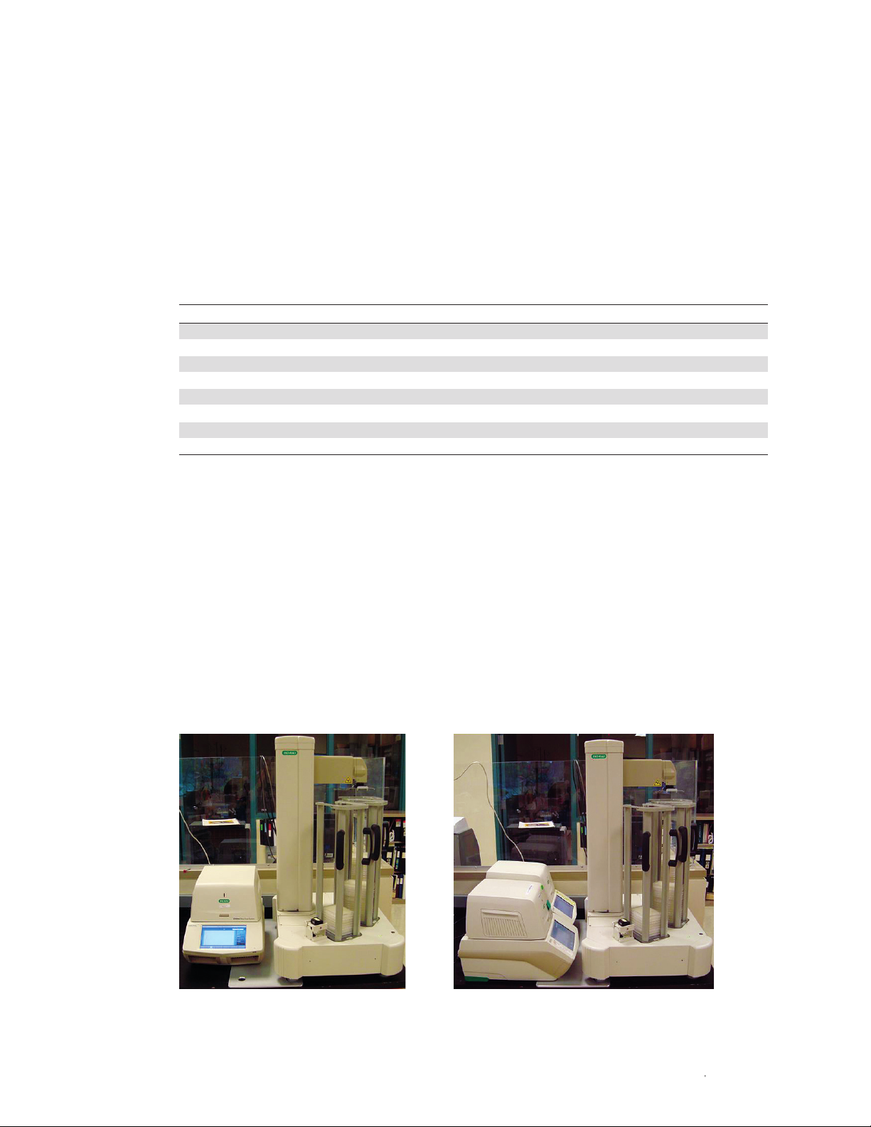
Determine the placement of the CFX System(s), plate handler, and computer on the lab bench.
If a single CFX System will be integrated, the CFX System front panel must face forward and be
located to the right of the plate handler (Figure 2A). If two CFX Systems will be integrated, the CFX
Systems must be installed with their front panels oriented toward the plate handler (Figure 2B).
A B
Fig. 2. Single and dual CFX Automation System II configurations.
| 3CFX Automation System II | 3
Page 12

Chapter 1: CFX Automation System II Installation
Space Requirements
The CFX Automation System II must be assembled on a sturdy, level lab bench. The benchtop
must be sturdy enough to support the weight of the computer, the plate handler, and the CFX
System(s) without sagging. An uneven surface will result in misalignment of the automation
system. Ensure there are sufficient electrical outlets available for the plate handler, CFX System(s)
and the computer. Table 9 illustrates the space requirements needed for the system.
Table 9. CFX Automation System II dimensions.
Operational Space
Footprint Requirements*
Single CFX Dual CFX Single CFX Dual CFX
Plate Handler System System System System
Dimensions Alone Configuration Configuration Configuration Configuration
Height, cm (in) 97 (38) 97 (38) 97 (38) 97 (38) 97 (38)
Width, cm (in) 53 (21) 91 (36) 99 (39) 91 (36) 114 (45)
Depth, cm (in) 77 (30) 77 (30) 77 (30) 86 (34) 86 (34)
* Operational space includes space for the plate handler arm travel and CFX System lid to open.
Tools required to assemble and install the CFX Automation System II include:
■n
Adjustable wrench
■n
Bubble level (provided with the system)
Unpacking the CFX Automation System II
WARNING! Use two people to lift the CFX Automation System II. The plate handler weighs
approximately 110 lb (50 kg). Lift the plate handler with care. Do not lift the plate handler by the
arm. Lift only by the base. Take precautions to avoid injury.
■n
Examine the carton for damage
■n
Remove the outer carton
■n
Remove the startup kit packaging on top of the plate handler. Make sure the startup kit is not
stuck in the top of the outer carton
■n
Retain the box and packing materials. If the unit needs to be returned for any reason, you
must use the original packing materials and box for shipping. If there has been damage to the
instrument in transit, it is particularly important to retain the packaging for inspection
Parts List
The shipping cartons should include the following items:
■n
Plate handler with attached barcode scanner
■n
Three removable racks
■n
Declaration of Conformity
■n
Startup kit containing:
- Power cord
- Communications cable [6 ft (1.8 m),
USB-B to USB-A]
- Calibration block
- Mounting plate
- Bubble level
- Eight extra gripper pads
- Two plate lifters for use with CFX384 Systems
- CFX Automation System II instruction manual
- CFX Automation Control Software
installation CD
- Ex tra fus es
- Warranty card
- Software registration card
4 | CFX Automation System II4 |
Page 13

Position the Mounting Plate and Plate Handler
Position the mounting plate on the bench such that the two holes for the plate handler feet are
on the right and the beveled edge faces up (Figure 3).
Lift the plate handler and place the two left feet inside the designated holes on the mounting
plate. The barcode scanner should be located in the front left.
WARNING! The plate handler weighs 110 lb (50 kg). Do not lift the plate handler by the arm.
Lift only by the base. Take precautions to avoid injury.
Beveled edge faces up
Back lef t foot of the plate handler will be
placed in this hole
Single CFX System configuration. Right feet of
the CFX System will be placed in these holes
Chapter 1: CFX Automation System II Installation
Dual CFX System configuration. Front feet of
the CFX Systems will be placed in these holes
Front left foot of the plate handler will be
placed in this hole
Fig. 3. Mounting plate.
Carefully cut the tie-wrap with the red sticker from the counterbalance rail and remove the
tiewrap and the black split tubing (Figure 4).
Fig. 4. Remove tie-wrap and black split tubing.
| 5CFX Automation System II | 5
Page 14

Chapter 1: CFX Automation System II Installation
Install the CFX System(s)
1. Install the CFX System(s) in the desired positions.
■n
Single CFX System. Align the right side feet of the CFX System in the mounting plate
such that the CFX System front panel is facing forward (Figure 2)
■n
Dual CFX Systems. Align the front feet of the CFX Systems in the mounting plate such
that the CFX Systems’ front panels are facing the plate handler (Figure 2)
2. Connect CFX System(s) power cord(s) and communication cable(s). For detailed
instructions on installing the CFX Systems, refer to the CFX Systems instruction manual
(bulletin #10021337).
3. Install the plate lifter (Figure 5) in all 384-well CFX Systems configured with the plate handler.
The plate lifter aids in the removal of 384-well plates by gently lifting the plate slightly out of
the reaction block when the heated lid is opened.
Note: The plate lifter is not required for 96-well CFX Systems. Save unused plate lifters for
potential future use with 384-well CFX Systems.
■n
Place the plate lifter around the outside of the 384-well block, with the lifters facing up
(Figure 5)
■n
Gently press down on the long edges of the plate lifter until the four notches on the short
side of the plate lifter push against the 384-well block
■n
Examine the plate lifter to ensure that it is properly installed
Fig. 5. Plate lifter for 384-well CFX Systems.
Level the Plate Handler
WARNING! This step requires two people. The plate handler weighs 110 lb (55 kg). When
lifting, grasp only the bottom of the plate handler. Do not lift the system by the arm.
Note: The bench top must be able to support the weight of the computer, the plate handler
and the CFX System(s) without sagging. An uneven surface will result in the misalignment of the
plate handler.
Lifters face upward
Press down here
Notches push into block
6 | CFX Automation System II6 |
Page 15
Chapter 1: CFX Automation System II Installation
Fig. 6. Bubble level in CFX System block.
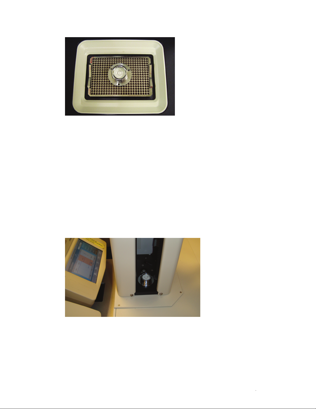
1. Place bubble level in the center of the CFX System(s) block (Figure 6). Note where the
bubble is within the level.
2. Lift the plate handler arm up high enough to access the tower opening. Place the level
inside the center of the plate handler tower (Figure 7). Compare the position of the
bubble to its position when placed on the CFX System block. Because the CFX Systems
do not have leveling feet, the most important thing is to level the plate handler relative
to the CFX System(s).
■n
If the bubble position differs significantly in the plate handler tower and CFX System(s),
proceed to step 3
■n
If the bubble position does not differ significantly when placed in the plate handler tower
and CFX System(s), proceed to step 6
Fig. 7. Bubble level in tower.
| 7CFX Automation System II | 7
Page 16

Chapter 1: CFX Automation System II Installation
3. Turn the securing nut down toward the bench until it rests against the adjusting nut
(Figure 8). Repeat on all four foot assemblies.
Tip: Have one person slightly lift the corner of the instrument while another person turns
the securing nut.
WARNING! The plate handler arm may swing when the instrument is lifted. Take
precautions to avoid injury.
Base
Securing nut
Screw threads
Adjusting nut
Foot
Fig. 8. Foot assembly.
4. Turn the adjusting nut until approximately two screw threads are visible between the plate
handler base and the securing nut. This will allow for adequate travel in either direction
during the leveling process. Repeat on all four foot assemblies.
5. Begin leveling the plate handler by turning the adjusting nut as needed until the bubble
matches the position when the level is placed on the CFX System(s). You may need to raise
one foot assembly and lower another during the leveling process.
Note: Rotating the foot itself will not change the height of the foot assembly. To level the
plate handler, you must rotate the adjusting nut.
6. Push down on all four corners of the plate handler base to ensure the system is evenly
seated on all four feet. All four feet must touch the bench for the instrument to be secure.
Although the bubble in the level may appear centered, if any of the feet are not on the
bench, the instrument is not secure.
7. When the plate handler is level, use an adjustable wrench to turn each securing nut upward
until it is flush against the system base. Hold the foot and adjusting nut in place while
turning the securing nut to ensure the plate handler remains level during this step. This step
locks the plate handler into the desired level position.
Install the Racks
1. Lift a rack by the two side handles.
2. Hold the rack over the designated position with the two side handles facing toward you. The
racks and rack positions are labeled and must be paired accordingly.
3. Lean the top of the rack toward you slightly.
8 | CFX Automation System II8 |
Page 17

Chapter 1: CFX Automation System II Installation
4. Place the rack locator notch under the lip of the rack position (Figure 9).
5. Maintain the placement of the rack under the lip while you lean the rack backward and
snap it into place against the locator pin.
Locator pin
Locator
notch
Fig. 9. Rack securing position.
6. Before releasing the rack, make sure it is firmly secured under the lip by gently pulling it
toward you. Release gently in order to maintain the proper position.
Note: If the rack is not correctly placed under the lip, the rack will not be level. This will
misalign the racks and the plate handler will not function properly.
7. Verify the region of the plate handler that holds the racks is level relative to the CFX
System(s). Place the bubble level at the bottom of each empty rack. Compare the position
of the bubble when the level is placed in the racks, in the tower, and on the CFX System(s)
block(s). If the racks are not level, adjust the plate handler foot assemblies so that all regions
of the plate handler are as level as possible, relative to the CFX System(s) (see Level the
Plate Handler).
To remove a rack, reverse the steps above.
Connect the Power Cord and Communications Cable
WARNING! Before proceeding, verify the plate handler power switch is OFF and the computer
power cord is unplugged.
LIp
1. Connect one end of the USB cable to the USB connector on the back of the plate handler
(Figure 10).
2. Connect the other end of the USB cable to an available USB port on the computer.
| 9CFX Automation System II | 9
Page 18

Chapter 1: CFX Automation System II Installation
3. Connect the power cord to the receptacle on the back of the plate handler (Figure 10).
4. Plug the plate handler AC power cord into a grounded 100 V, 120 V, or 240 V outlet.
5. Plug the computer AC power cord and the computer monitor AC power cord into
appropriate power outlet.
WARNING! Plug the power cord into a properly grounded outlet only. Use only a standard
IEC 60320-style power cord appropriate for your country. Equipment is Class 1 and must be
connected to an outlet that has proper grounding to ensure safety. The power inlet is a basic
disconnect device and should be positioned for easy access.
USB connector Power switchPower cord
Fig. 10. Rear panel of the CFX Automation System II.
Software Installation
receptacle
10 | CFX Automation System II10 |
CFX Manager Software 3.1.1620 or higher must be installed first to run the CFX Automation
System II. Refer to the CFX System instruction manual (bulletin #10021337) for detailed
instructions on CFX Manager Software installation.
The CFX Automation Control Software must be installed on the computer by a user with
administrative privileges. To install CFX Automation Control Software 2.0 or higher:
1. Place the CFX Automation Control Software CD in the computer CD drive.
2. Double click setup.exe to launch the software installation.
3. Click box for Accept license agreement. Click Install.
4. Click Extract for FTDI Chip CDM Drivers.
5. Click Next on the software installation screen.
6. Click Finish to exit device driver installation wizard.
Page 19

Chapter 1: CFX Automation System II Installation
7. Click Next for the CP210X USB to UART Bridge Driver Installer.
8. Select radio button I accept this agreement. Click Next.
9. When the software installation is complete, click OK to exit the installation wizard.
10. When completed, the CFX Automation Control Software icon appears on the desktop.
Note: To uninstall CFX Automation Control Software from your computer, use the Windows
Add/Remove Programs function.
Enable Computer to Continuously Communicate with Barcode Scanner
Default power management settings for the barcode scanner must be modified to enable the
system to function properly. To modify the power management settings:
1. Find the computer device manager by typing device manager into the computer’s
search field.
2. Expand the Ports (COM & LPT) option by clicking its arrow (Figure 11A).
3. Double click Silicon Labs CP210x USB to UART Bridge.
4. Select the Power Management tab (Figure 11B).
5. Clear the checkbox next to Allow the computer to turn off the device to save power.
A B
Fig. 11. A, device manager folder. B, modify the power management options for the barcode scanner.
| 11CFX Automation System II | 11
Page 20

Chapter 1: CFX Automation System II Installation
Turn Off Windows Automatic Update Feature
When the Windows automatic updating feature is turned on, updates will be automatically
installed and the computer will automatically restart. If these Windows automatic updates occur
when an automation run is in progress, the run will be stopped and the application will close.
No error messages will be displayed. To prevent this from occurring, turn off the Windows
automatic updating feature and manually install Windows updates as needed.
CFX Automation System II Configuration and Calibration
After the CFX Automation System II, CFX System(s), CFX Manager Software, and CFX
Automation Control Software are installed, follow these steps to complete instrument setup:
■n
Configure the Automation System
■n
Calibrate the Automation System
■n
Test the Calibration
■n
Complete a Test Automation Run
Configure the Automation System
System configuration must be set during system installation, when CFX Systems are added or
removed and when optical modules are swapped on C1000™ Thermal Cycler bases.
1. Turn on the CFX System(s) and the plate handler using the power switches on the back of
the instruments.
2. Open the CFX Automation Control Software.
3. In the menu bar, select Tool s > Configuration. The platform configuration window will
appear (Figure 12).
4. Select Single CFX System or Dual CFX Systems according to your setup.
5. Under Platform Configuration:
■n
Use the dropdown menu to select the CFX System base serial number corresponding
to the configured CFX System. The base serial number can be found on the back of
the instrument base, and on the home screen display on systems with touch screens
(Figure 13). If only a single CFX System is configured, select the serial number for that
system next to the “front” CFX System. If two CFX Systems are configured, select
the appropriate CFX System base serial number for the front and rear CFX Systems
(Figure 1). Note that all CFX Systems and 1000-series thermal cyclers connected to this
computer will be displayed in the dropdown menu
■n
If you are switching just the optical modules and the thermal cycler base will remain the
same, first select NOT USED from the dropdown menu. Then select the appropriate serial
number again. This process will enable the software to recognize the new optical head
■n
Select the desired waste rack
6. Select OK to save configuration
■n
Each time the system configuration window is modified, the software will
automatically restart
12 | CFX Automation System II12 |
Page 21

Fig. 12. Platform configuration window.
Chapter 1: CFX Automation System II Installation
Serial number located on the
base of the instrument.
Fig. 13. Base serial number locations.
Calibrate the Automation System
The CFX Automation System II must be properly calibrated during installation. Recalibrate any
time the system is moved or CFX Systems are added or removed.
Default calibrations for your CFX System configuration are automatically loaded during the
system configuration step. The automation software includes a calibration wizard that aids in
making the fine adjustments required for proper calibration. To calibrate the system:
■n
Select Tool s > Calibration
■n
Select the positions to calibrate
Home screen on CFX System
touch screens. Base serial number
is located on this screen.
| 13CFX Automation System II | 13
Page 22

Chapter 1: CFX Automation System II Installation
■n
Select Calibrate
■n
The calibration wizard will walk you through the steps to calibrate, modify, and accept
each calibration position. At each step, carefully read the instructions presented and
perform the required actions. If calibration modification is required, manually adjust the
plate handler by moving the arm to the desired location
■n
Select Next. Instructions for the next calibration step will automatically appear
This manual provides additional details to supplement the information displayed in the
calibration wizard.
During calibration, refer to the following sections:
■n
Begin Calibration
■n
Calibrate the Racks
■n
Calibrate the Barcode Scanner
■n
Calibrate the CFX System(s)
After calibration is complete, test the calibration using the calibration wizard.
Lastly, confirm calibration by completing a test automation run.
Begin Calibration
During installation, factory calibration values are loaded. These values are starting points for
calibration and must be adjusted as needed. If the system requires calibration at any of the
positions, manually adjust the plate handler by moving it to the correct calibration position.
When instructed by the software, the robot arm can be moved along the vertical axis and
horizontal axis and extended in and out from the tower (Figure 14). The wrist can be rotated to
help obtain ideal calibration.
WARNING! Adjust the plate handler only when instructed. Manually adjusting the plate handler
at other times may damage the instrument.
Gently pull out or
push in the arm to
change the reach
Rotate the wrist
to obtain proper
calibration
The rotary axis
can be modified
to obtain proper
calibration
Gently push up
or pull down the
arm to adjust the
vertical position
14 | CFX Automation System II14 |
Fig. 14. Manually changing positions during calibration.
Page 23

Chapter 1: CFX Automation System II Installation
When calibrating the plate handler, always use the same brand and model of PCR plates that
will be used in experiments. See Table 7 for a list of plates compatible with the automation
system. All plates should be sealed. If both CFX96 and CFX384 Systems are being used, the
calibration instructions will indicate which positions should use 96-well and 384-well plates.
WARNING! Stand clear of the plate handler arm throughout the calibration process.
To begin calibration:
1. In the menu bar, select Tools > Calibration.
2. The main calibration screen is displayed (Figure 15).
3. Select the positions to calibrate.
■n
All positions should be calibrated during installation. After installation, specific positions
may be recalibrated
■n
If you will always or occasionally use barcoded plates, calibrate the barcode scanner
during the initial installation. This will ensure a smooth automation run when the barcode
software options are selected
4. Select Calibrate.
5. Carefully follow the instructions that appear in the calibration window and then select Next
to continue through calibration. The system will execute the appropriate calibration steps
and then display the next set of instructions.
Select all
positions to be
calibrated
Save or cancel
calibration
Exit calibration
wizard
Fig. 15. Main calibration and test window.
Calibrate the Racks
The instructions on the calibration screen will guide you through the calibration of the racks.
1. Place a single sealed PCR plate at the bottom of each rack. Well A1 should face out toward
the exterior of the plate handler.
Note: Use the same brand and model of the plates that will be used in actual automation
runs. If both 96-well and 384-well CFX Systems are connected to the plate handler, use a
384-well plate to calibrate the bottoms of all three racks.
Carefully read
and follow all
instructions
displayed
Provides status
information
| 15CFX Automation System II | 15
Page 24

Chapter 1: CFX Automation System II Installation
2. When instructed by the software, place the calibration block on top of the rack to be
calibrated (Figure 16). The calibration block is larger than a PCR plate and is designed to sit
on top of the rack and aid in this calibration position.
3. The top of the rack is properly calibrated when the gripper fingers are perfectly centered on
the calibration block (Figure 16).
4. If the calibration needs to be adjusted, manually adjust the plate handler only when
instructed by the software.
5. If needed, adjust the calibration by manually separating the gripper fingers from the
calibration block. Extend or retract the plate handler arm the appropriate amount so that
the gripper fingers will be centered on the calibration block. Release the gripper fingers and
inspect their location on the calibration block. Repeat as needed.
6. Follow the calibration wizard instructions to complete rack calibration.
Fig. 16. Calibrating the racks.
Calibrate the Barcode Scanner
1. Place a sealed plate in rack 1.
Note: If both 96-well and 384-well CFX Systems are configured, use a 384-well plate for
this step.
2. The plate handler will move the plate from rack 1 to the barcode scanner. Confirm that the
barcode on the short side of the plate is facing the barcode scanner.
3. To be properly calibrated, the LED light from the barcode scanner should illuminate the
region immediately above the plate barcode or at the very bottom of the gripper assembly
(Figure 17). Manually adjust the plate handler arm and gripper assembly if not properly
positioned. Ensure the plate handler arm remains fully extended.
Note: For the software to properly calibrate the barcode scanner, the LED beam must
illuminate the region above the top of the barcode sticker.
4. Select Next. The software will now calibrate the barcode scanner.
Properly calibrate the top
of the rack by making sure
the gripper fingers grasp
the calibration block with
an equal number of black
pyramids on each side.
16 | CFX Automation System II16 |
Page 25

Chapter 1: CFX Automation System II Installation
Position the plate handler arm so the beam
illuminates the region slightly above the top of the
barcode sticker. It should be illuminating the very
bottom of the gripper assembly.
Fig. 17. Calibrating the barcode scanner.
Calibrate the CFX System(s)
1. Place a sealed plate in the CFX System(s).
2. Keep the CFX System(s) lid(s) open.
3. The gripper assembly will move to the CFX System and stop approximately one inch above
the plate. At this point, confirm that the gripper assembly is approximately centered above
the plate.
■n
This step confirms the general location of the gripper assembly. Do not lower the plate
handler arm down toward the plate at this step
■n
If the gripper assembly is misaligned by a large amount, you may make manual
adjustments at this point. Fine adjustments to the calibration will be made in the next step
4. Select Next. The gripper assembly will move down and grip the plate. Confirm that the
gripper assembly is centered on the plate (Figure 18).
■n
Confirm the gripper fingers are centered, touching the plate with equal distance from the
notches on the plate
■n
Confirm that the top of the gripper assembly is squared on the plate, overhanging the
plate by equal amounts
■n
If changes need to be made, carefully spread the gripper fingers, releasing them from the
plate. Continue to hold the gripper fingers open. Move the gripper assembly as needed
so that it is centered on the plate. Gently release the gripper fingers and examine if the
gripper assembly is centered on the plate (Figure 18). Repeat until properly centered
5. Select Next.
| 17CFX Automation System II | 17
Page 26

Chapter 1: CFX Automation System II Installation
6. The plate handler will pick up the plate, place it in rack 1 and then return the plate to the
CFX System. Confirm that the plate transitions smoothly between all positions.
Once all positions are calibrated, select Save. The application will automatically restart and
load the saved calibration. Select Cancel to cancel any modifications that were made to the
calibration and restore the previously set calibration values.
Gripper fingers are equal distance from
each of the notches on the plate.
Fig. 18. Calibrate the CFX Systems.
Test the Calibration
You must test all calibration positions to verify calibration is correct.
1. Select To ols > Calibration.
2. Select all positions that will be used during the automation run.
3. Select Test . The automation system will proceed through a series of steps ensuring that all
calibration settings work together.
18 | CFX Automation System II18 |
Gripper assembly overhangs the plate
by equal amounts on both sides.
Page 27

4. Carefully observe the entire test process. Confirm the gripper assembly smoothly picks up
and releases plates, the plate is perfectly placed into the CFX System(s) and plates never
scrape against the racks.
5. If any of the calibration positions fail, a message will alert you to the failed position. You can
instruct the system to continue testing the other positions.
6. When testing is complete, recalibrate the failed positions. After calibration is complete, test
these positions.
Complete a Test Automation Run
After calibration and testing is complete, set up a plate list and run several empty plates through
an automation run before actual experimental plates are used. Plates can remain empty but
must be sealed. Use short cycling protocols in CFX Manager Software to reduce the amount of
time required for this final recommended test.
Carefully observe the entire test automation run. Confirm the gripper assembly smoothly picks
up and releases plates, the plate is perfectly placed into the CFX System(s), and plates never
scrape against the racks. If the entire test automation run completes correctly, the automation
system has been correctly installed and calibrated and is ready for use.
Chapter 1: CFX Automation System II Installation
| 19CFX Automation System II | 19
Page 28

Chapter 1: CFX Automation System II Installation
20 | CFX Automation System II20 |
Page 29

2
Using the CFX Automation System II
Read this chapter for information about using the CFX Automation System II.
■n
Introduction
■n
Starting an Automation Run
■n
Adding Plates after Starting an Automation Run
■n
Canceling an Automation Run
■n
Pausing or Canceling a Single Plate Run in a CFX System
■n
Emptying the Waste Rack
■n
LIMS Information
■n
PrimePCR™ Information
■n
Create the Plate List: Additional Features
■n
Barcode Controls: Advanced Features
■n
Modify Settings
■n
Sta tus Ta b
■n
History Tab
Introduction
CFX Automation Control Software and CFX Manager™ Software are used together to
automate CFX System(s). The automation software controls the plate handler and is the main
interface for controlling all automation processes. CFX Manager Software is used to create
plate setup files and cycling protocols, control the CFX System thermal cycling processes,
and analyze data. Refer to the CFX System instruction manual (bulletin #10021337) for
detailed information about CFX Manager Software. To use CFX Manager Software and the
automation software simultaneously, CFX Manager Software must be opened prior to
the automation software.
CFX Automation System II | 21
Page 30

Chapter 2: Using the CFX Automation System II
Open the CFX Automation Control Software by double clicking the automation system icon. The
main software tabs in the CFX Automation Control Software include:
■n
Status tab. Illustrates the status of the plate lists, the configured CFX System(s), and the
waste rack
■n
Plate list tabs. Named according to the rack on which the source plates are loaded
■n
History tab. Provides a log of plates run using the CFX Automation System II
Plate list tabs History tab
Status tab
Selection box
to highlight an
entire row
Select barcode
cell to be
modified
Plate list
controls
Fig. 19. Plate list tab.
Starting an Automation Run
The plate list is the table that contains the cycling instructions for all plates loaded into a specific
source rack (Figure 19). The plate list tabs are named according to the rack in which the source
plates are loaded (Rack 1, Rack 2, etc). View each of the plate lists by selecting either of the
plate list tabs on the main tool bar. All controls for creating, editing, saving, and running plate
lists are found on the plate list window.
CFX System selection
Import LIMS or
PrimePCR run
ID as barcode
Barcode
controls
Basic automation runs can be started by following these five steps:
1. Create the plate list.
2. Select the CFX System(s).
3. Modify the barcode controls.
4. Load the plates.
5. Select Start.
CFX Automation System II22 |
Page 31

Step 1: Create the Plate List
Use the plate list controls (Figure 19) to add plates to a plate list:
■n
Select protocol, LIMS, or PrimePCR file — use the dropdown menu or browse function
to select the desired protocol, Laboratory Information Management Systems (LIMS) file, or
PrimePCR file. Protocols must be created and saved using CFX Manager Software. Because
LIMS and PrimePCR files contain both protocol and plate information, when one of these files
is selected, the plate file dropdown box will be disabled. For additional information on LIMS,
see LIMS Information. For additional information on PrimePCR, see PrimePCR Information
■n
Select plate file — use the dropdown menu or browse function to select the desired plate
file. Plate files must be created and saved using CFX Manager Software
■n
Select Add — a new entry with the selected files will be added to the plate list. If no rows on
the plate list are selected, the new entry will be added to the bottom of the plate list. If a row
in the plate list is selected, the new row will be inserted directly below the selected row
Tip: See Create the Plate List: Additional Features for tips to quickly add files to a plate list and
information on editing and saving plate lists.
Step 2: Select the CFX System(s)
If a single CFX System is configured, all plates will automatically go to that CFX System and this
step can be skipped.
Chapter 2: Using the CFX Automation System II
If two CFX Systems are connected, designate the CFX System(s) on which the plates should be
run. Select Front CFX System and/or Rear CFX System on the desired plate list (Figure 19). If
both 96-well and 384-well CFX Systems are configured, each CFX System must be controlled
by an individual plate list and the source rack must contain only 96-well or 384-well plates.
Note: If two separate plate lists have the same CFX System(s) selected, the software will
alternate running plates from each plate list until the automation run is complete.
Step 3: Modify the Barcode Controls
Select or deselect the Scan Barcodes option in the barcode controls section of the plate list
tab (Figure 19).
Select the Match Barcodes option to match scanned barcodes to plate list barcode
information and pair the cycling and plate protocols accordingly.
For more information on barcode options, see Barcode Settings: Advanced Features.
Step 4: Load the Plates
If using Bio-Rad’s Microseal® 'B' optical seals, peel off the seal end tabs after sealing the
plates. Place the plates in the source rack. The source rack can be identified by the tab name
on the plate list page, for example Rack 1. Well A1 should face out toward the exterior of the
plate handler (Figure 20).
CFX Automation System II | 23
Page 32

Chapter 2: Using the CFX Automation System II
Fig. 20. Plate well A1 faces outward.
We ll A1
Step 5: Begin the Automation Run
Before beginning, confirm:
■n
Plates are placed in the input rack defined in the plate list window (Figure 19)
■n
Plates are placed with well A1 facing outward, away from the plate handler tower (Figure 20)
■n
If two CFX Systems are configured with the plate handler, the desired CFX System(s) is/are
selected (Figure 19)
■n
Confirm Match Barcodes is selected if scanned barcodes should be matched with
associated cycling protocols
■n
If configured CFX System(s) are also used in manual mode, confirm plates from former
experiments have been removed from the CFX System block
Select Start on the plate list tab. The automation run will begin.
Adding Plates after Starting an Automation Run
You may add additional plates after an automation run has begun. To do this:
■n
Select the plate list window to which plates will be added
■n
Highlight the row under which you would like to add additional plates
■n
Select the desired protocol and plate files (or LIMS or PrimePCR file) and select Add
■n
Add the plates to the appropriate place in the input rack
Note: If Match Barcodes is not selected, the location of the plate in the plate list must match
the physical location of the plates in the rack. Failure to correctly match orientations will lead to
the incorrect pairing of cycling protocols with the plate.
WARNING! When using this feature, the plate handler arm will move to exchange plates at
the appropriate time. Take care to ensure that you do not obstruct the movement of the plate
handler arm when adding plates.
24 | CFX Automation System II
24 |
Page 33

Chapter 2: Using the CFX Automation System II
Canceling an Automation Run
To cancel an entire automation run:
■n
Select the plate list window corresponding to the automation run to be canceled
■n
Select Cancel
Any plates being cycled in a CFX System originating from that plate list will be canceled. The
plate handler will remove the plate(s) from the CFX System(s) and place them in the waste rack.
The automation run will be completely stopped. All plates not thermal cycled will be labeled
“Not Run” in the status column.
Note: If two plate lists are running simultaneously using different CFX Systems, each plate list
must be canceled separately.
Pausing or Canceling a Single Plate Run in a CFX System
You may pause or stop a single plate either through the CFX System or CFX Manager
Software. Remember, selecting Cancel in the CFX Automation Control Software cancels the
entire automation run, not a particular plate. See Canceling an Automation Run (above) for
more detail.
Note: CFX Manager Software must be opened before CFX Automation Control Software to use
both applications simultaneously.
To stop a single plate run, select Cancel on the CFX System or Stop in CFX Manager Software.
All end-of-run processing will occur using the incomplete data generated to that point and the
plate handler will move the plate to the waste rack. The automation run will continue with the
next plate in the plate list.
To pause a single plate run, select Pause on the CFX System or in CFX Manager Software.
Resume the cycling protocol using the CFX System or CFX Manager Software. The automation
software will wait until the run is resumed or canceled to continue using that CFX System for
the automation run. If the plate list is feeding plates to two CFX Systems, the automation run will
continue using the other CFX System.
Emptying the Waste Rack
The waste rack may be emptied any time the plate handler is not actively performing an operation.
The plate handler checks the waste rack capacity immediately before removing a plate from a
CFX System and placing it in the waste rack. Plates should not be emptied from the waste rack
during this time.
You can set up automatic email notifications to alert you when the waste rack is approaching
full. See Emails and Notifications for more information.
LIMS Information
The CFX Automation System II can be integrated with Laboratory Information Management
Systems (LIMS) to facilitate automation and information flow. All LIMS integration is managed
through CFX Manager Software.
| 25CFX Automation System II
| 25
Page 34

Chapter 2: Using the CFX Automation System II
The CFX System instruction manual (bulletin #10021337) explains in detail the steps required to
set up LIMS integration. These steps include:
■n
Setting up a LIMS folder and data export options
■n
Creating a LIMS file (*.plrn) using the provided CFX96™ or CFX384™ LIMS Plate Import
Template files. Detailed definition of the LIMS Plate Import Template file content is provided
■n
Exporting data as a LIMS file
To complete LIMS integration, CFX Manager Software requires plate setup information
generated by the LIMS platform, a protocol file created using CFX Manager Software (*.prcl), a
defined data export location, and a defined export format. The LIMS file created by your internal
LIMS contains the plate setup details and the protocol file name. CFX Manager Software will
use the LIMS file to create a plate file that will be used in conjunction with the named protocol
file to start a run and generate data. Refer to the LIMS Integration Section in the CFX System
instruction manual (bulletin #10021337) for more detail.
When LIMS files are created for use with the automation system, plate barcode information
provided in column B, row 8 of the LIMS file (the Run ID field) can be directly imported into the
automation software (see Entering Barcode Information into a Plate List). Information entered in
column B, row 11 of the LIMS file (the Data File field) can be used to name data files, reports,
and export files (see File Name Format).
Once LIMS integration is complete, LIMS files may be loaded into the automation software and
LIMS data export files can be generated.
PrimePCR Information
Bio-Rad offers 96- and 384-well PrimePCR plates that contain primer pairs lyophilized in
the plate wells. You may customize the genes on the plates or choose from a wide variety of
predesigned disease- and pathway-specific panels. For more information, go to
www.bio-rad.com/primepcr.
Bio-Rad provides run files containing gene layout and cycling protocol information for all
PrimePCR plates. Run files for predesigned and custom plates can be downloaded from
www.bio-rad.com/primepcr. Run files for custom plates are saved under My PrimePCR
once configured and purchased. To obtain run files for predesigned panels, select Run File on
the Review Plate webpage.
Once the run files are downloaded, easily load PrimePCR files into any automation plate list
using the plate list controls.
Create the Plate List: Additional Features
Quickly Add Rows to the Plate List
■n
Add multiple rows with the same protocol and plate files (or same LIMS or PrimePCR
files). Enter the desired number of plates in the Rows box before selecting Add
■n
Apply identical protocol and plate files (or LIMS or PrimePCR files) to all plates in a
rack. Enter the protocol and plate file (or LIMS or PrimePCR file) into a single row and select
Repeat row 1 until rack is empty. The protocol and plate files will be applied to all plates
in the input rack. Each time a new plate is retrieved from the source rack, a new row will be
automatically added to the plate list. This option is available only when a single row is defined
in the plate list
CFX Automation System II26 |
Page 35

Chapter 2: Using the CFX Automation System II
■n
Add multiple LIMS or PrimePCR files to a plate list at once. Select Browse, select
all desired LIMS or PrimePCR files, and select Open. Each LIMS or PrimePCR file will be
automatically added as a unique row on the plate list
■n
Add multiple rows with the same protocol file but different plate files. Select the desired
protocol file using the dropdown menu or browse button. Select Browse in the plate file field
and open the folder that contains multiple plate files of interest. Select all desired plate files
and select Open. Each plate file will be paired with the protocol file and automatically added
to the plate list
■n
Add multiple rows with the same plate file but different protocol files. Select the desired
plate file using the dropdown menu or browse button. Select Browse in the protocol file field
and open the folder that contains multiple protocol files of interest. Select all desired protocol
files and select Open. Each protocol file will be paired with the plate file and automatically
added to the plate list
Note: The maximum number of rows that can be added to a plate list is 1,000.
Edit a Plate List
Select the row to be modified by clicking on the selection box for that row (Figure 19). Multiple
rows may be selected by using the shift and control keys. After selecting the desired rows,
you may:
■n
Modify the protocol, LIMS, PrimePCR, or plate file using the dropdown menu or browse options
■n
Modify the order of the selected row by selecting Move up or Move down
■n
Delete a row by selecting Delete
■n
Clear an entire plate list by selecting Clear
Enter in notes for any row by selecting the desired notes cell in the plate list. All notes typed
in the automation software will be stored in the CFX Manager Software data file.
Save a Plate List
By default, new plate lists are named “Untitled_rackX”. Save a plate list
by selecting File > Save. The default directory for saved plate lists is:
C:\Users\Public\Documents\Bio-Rad\CFXAutomationSystem\UserData. The saved
plate list file also stores the selected CFX System(s) and barcode selections. However,
the information specified under the Settings selection is not saved with the file.
You may load a previously saved plate list file by selecting File > Open and choosing the
desired plate list file. Modifications to the plate list file can be saved by selecting File > Save.
Modifications can be saved as a new plate list by selecting File > Save As and giving the
plate list file a unique name.
Note: When loading a saved plate list file, remember that although CFX System(s) and barcode
selections are stored within the file, the information stored under Settings is not associated with
the plate list file. Carefully review the Settings each time a plate list file is loaded.
Barcode Controls: Advanced Features
Define If the System Should Scan Barcodes and/or Match Barcodes
Each plate list tab contains a barcode controls section (Figure 19) that permits you to modify
how the system applies barcode information. Table 10 provides an overview of system
response for the various options selected.
| 27CFX Automation System II
| 27
Page 36

Chapter 2: Using the CFX Automation System II
Define How the System Should Respond When Unable to Scan Barcodes or
Match a Barcodes
Table 11 provides an overview of options available for how the system should respond when
unable to scan or match a barcode.
Table 10. Barcode controls and associated system response.
Plate Scanned/Barcode System Response
Information Required System Response Options When Unable
Barcode Prior to Starting When Barcode is to Scan or Match
Controls Automation Run Scanned Barcode (Table 11)
No/No N/A N /A
Yes/No Barcode recorded in the next Pause and Notify,
plate list row Skip and Notify,
Protocol and plate file (or LIMS
or PrimePCR file) in the next
available row will be applied
Yes/Yes Protocol and plate file (or LIMS or Pause and Notify,
(see Entering Barcode PrimePCR file) associated with Skip and Notify
Information into a that barcode will be applied to
Plate List) the plate placed in the CFX System
The displayed order of the plate
list will be modified so that the
currently running plate is moved up
Run Plate Anyway
Table 11. System response when unable to scan or match a barcode.
Barcode Controls Plate Handler Response Plate List Response* Email Notifications Sent**
Plate placed in source Pauses Yes
rack
Plate placed in waste rack Continues running with Yes
the next plate
Plate placed in CFX Protocol and plate file (or No
System LIMS or PrimePCR file)
associated with next row
on the plate list will be
applied to the plate
* If another automation run is executing using a different plate list, that run will continue.
** Email addresses must be properly configured in CFX Manager Software in order for these emails to be received.
28 | CFX Automation System II
28 |
Page 37

Entering Barcode Information into a Plate List
Barcode information can be entered into the software and applied in a variety of ways,
described below.
■n
Manual entry — select the barcode cell that corresponds to the plate of interest (Figure 19).
Type in barcode information and then press the Enter key. The barcode cell for the next row
will be automatically highlighted
■n
External barcode scanner — connect an external barcode scanner to the computer. Select
the barcode cell corresponding to the plate of interest. Scan the plate. The barcode information
will be entered, and the barcode cell for the next row will be automatically highlighted
■n
Import LIMS or PrimePCR Run ID as barcode — CFX Manager Software LIMS and
PrimePCR Import Template files have a cell, B8, called Run ID. When Import LIMS or
PrimePCR Run ID as barcode is selected, barcode information in cell B8 of the LIMS or
PrimePCR file will be automatically loaded into the plate list
Note: This option must be selected before the LIMS or PrimePCR file is added to the plate list.
■n
Scan barcodes — no barcode information is loaded into the plate list prior to starting the
automation run. When Scan Barcodes is selected, all plates are moved to the barcode
scanner, scanned, and then placed in the CFX System. Barcode information is entered into
the plate list
Chapter 2: Using the CFX Automation System II
Modify Settings
Settings allow you to customize the way files are named, managed, and stored, and to customize
the email notifications. Each plate list tab is associated with a separate set of software
settings. These settings are saved when the software is shut down. The settings will be applied
to all plate lists created and used with that particular source rack. To modify the settings, select
Settings. A window displaying three tabs with modifiable settings is displayed (Figure 21):
■n
Plate List Details
■n
Reports
■n
Emails and Notifications
Note: When saving a plate list, modifications made in Settings are not saved with the plate list file.
Fig. 21. Settings window.
| 29CFX Automation System II
| 29
Page 38

Chapter 2: Using the CFX Automation System II
Plate List Details
Plate List Defaults
Customize the protocol, LIMS, or PrimePCR file and plate files displayed in the dropdown menu
when the application is opened. Because LIMS and PrimePCR files contain both protocol and
plate information within the single file, when these files are selected, the Plate File dropdown
box is disabled.
Data File Destination Directory
Specify the location for data files generated by CFX Manager Software. The data file directory
information set in this window overrides directory settings set in CFX Manager Software.
File Name Format
Use the dropdown menus to define the file name format. Free form text can be entered in the
prefix and suffix boxes. The time and date field is required in all file names. A preview of the
sample name is displayed.
Alternatively, file names can be directly imported from a LIMS or PrimePCR file by selecting Use
LIMS or PrimePCR Data File as name on the main plate list tab. The information entered in
the Data File field in the LIMS import file will be used as the file name (see LIMS Information).
Selecting this option will override any naming selection chosen in the dropdown menus.
Reports
Default Plate List
This allows you to have a particular plate list loaded each time the application is opened. By
default, no plate list is displayed. To have a plate list always displayed at application startup,
select Open this Plate List at Startup and choose a plate list you have previously saved.
Generate PDF Reports
By selecting this box, a PDF report will be automatically generated when a run is completed.
There is also a Report column on the plate list screen. This column allows you to easily
determine if a report will be generated. You may also create reports for individual plates by
selecting or deselecting this column for individual plates.
Report File Destination Directory
This section allows you to specify the storage location for the reports.
Use CFX Manager Default Report Template
This section determines the template used for reports. When selected, the report template
specified in CFX Manager Software will be used. To change the default report template in
CFX Manager Software, go to User > User preferences > Custom export and select the
export items you would like included.
30 | CFX Automation System II
30 |
Page 39

Emails and Notifications
Run Completion Notification
When Send Run Completion Notifications is selected, an email containing the data file will be
automatically sent at the completion of a run. Enter the desired email address in the text box.
Multiple email addresses can be entered by separating each address with a comma.
Tip: To receive report files in addition to data files, ensure Generate PDF Report is selected in
the Reports tab.
Other Notifications
This section enables the software to automatically email recipients regarding the status of
theautomation system. Options include:
■n
Notifications regarding the waste rack capacity. Enter in the percent capacity at which email
notifications should be sent
■n
Notifications for when a plate list has completed
■n
Notifications when the automation system has encountered an error
Status Tab
The Status tab provides an overview of the status of both plate lists and the waste rack
(Figure 22). When the automation software is in successful communication with the CFX
System(s), CFX System status information is displayed. The Status tab also displays
information on ongoing plate lists as well as waste rack capacity. Detailed plate list information
can be viewed by selecting Manage.
Chapter 2: Using the CFX Automation System II
Configured
CFX System
status
Plate list
name
View plate list
Fig. 22. Status tab.
| 31CFX Automation System II
| 31
Page 40

Chapter 2: Using the CFX Automation System II
History Tab
The History tab contains details of all automation runs completed since the last time the
application was opened (Figure 23). You may sort the history information by clicking on any
column header. By default, the information is sorted by date.
Run history files for automation runs completed in the past can be located using the following
file path: C:\Users\Public\Documents\Bio-Rad\CFXAutomationSystem\UserData.
Fig. 23. Histor y tab.
32 | CFX Automation System II
32 |
Page 41

3
Resources
Read this chapter for information about maintaining and troubleshooting the
CFX Automation System II.
■n
Maintenance
■n
Power Outage
■n
Troubleshooting the CFX Automation System II
■n
Frequently Asked Questions
Maintenance
Cleaning the CFX Automation System II
Wipe up any spills immediately.
■n
Avoid direct contact with spilled liquid
■n
Wear protective gloves and safety glasses
The outside surfaces of the plate handler should be cleaned periodically. Clean only the exterior
of the unit. Never remove any instrument covers to clean the inside of the instrument.
■n
Use a cloth or sponge dampened with water, alcohol, glass cleaner, or a mild soap solution
diluted with water
■n
If using glass cleaner or mild soap, wipe with a cloth or sponge dampened with water after
cleaning to remove any residue
■n
Do not use abrasive cleaners
■n
Do not spray cleaner onto the instrument
■n
Do not allow water or other fluids to drip inside the plate handler
Clean the gripper assembly and the racks with alcohol or other residue-free solvent. The
surface beneath the plate handler racks must be clean at all times. Debris or dust under the
racks will cause the plate handler and the racks to be out of calibration.
CFX Automation System II | 33
Page 42

Chapter 3: Resources
Changing the Fuses
WARNING! Electrical shock hazard. Disconnect the power cord before changing the fuses.
WARNING! For continued fire protection and correct system functioning, replace fuses only
with exact part number.
To change the plate handler fuses:
1. Verify the plate handler power switch is OFF and the power cord is unplugged from the
instrument.
2. Using a small flat-blade screwdriver at the top of the fuse housing, gently pry the fuse
housing (Figure 24) out of the power entry port.
3. Remove the two 2.5 A fuses.
4. Replace both fuses with fuses with the same part number.
5. Confirm that the fuses are seated securely in the fuse housing.
6. Snap the fuse housing back into the power entry port.
Pry here
Fig. 24. CFX Automation System II power entry port.
Power Outage
If a power outage occurs during operation of the CFX Automation System II, the grippers
will open and the plate will drop when the power is restored. If you routinely operate the CFX
Automation System II overnight or with valuable samples, consider using a 900 W (or greater)
uninterruptable power supply (UPS) to each connected instrument to provide a backup power
source for the CFX Automation System II, the CFX System(s), and the computer.
Troubleshooting the CFX Automation System II
This section describes how to view automation system logs. It also includes a list of potential
problems that may be encountered when using the system, along with their solutions. If you
continue to experience problems after following the instructions below, contact Bio-Rad
Laboratories technical support.
CFX Automation System II34 |
Page 43

View Logs
The CFX Automation Control Software tracks information about the state of an instrument
during an automation run. Use these logs to track events that occur on instruments and in the
software, and for troubleshooting. To open the log, select Tools > View Log.
Logs are also stored in file folders. The file path to access these files is:
C:\ProgramData\Bio-Rad\CFXAutomationSystem\Logs.
Error Messages
Error messages inform the user of problems requiring immediate attention. If an error occurs
during operation, the CFX Automation System II stops and an error message is displayed on
the computer screen. Error messages along with the probable causes and possible solutions
are listed in Table 12.
Table 12. Error messages, possible causes, and solutions.
Error Message Possible Cause Possible Solution
Another instance of The automation software was To use both CFX Manager Software and
CFX Manager
already running CFX Manager Software time, open CFX Manager Software first
Plate list [xx] has paused. Unable to Incompatible plates may be The CFX Automation System II is
load plate in CFX System. Check for being used compatible with Hard-Shell
obstructions. Restart or cancel the 96-Well and 384-Well Skirted PCR
plate list after correcting the issue Plates. See Table 7 for detailed ordering
information.
Plate list [xx] has paused. Unable to The CFX Automation System II Test the calibration using the calibration
load plate in CFX System. Check for is not properly calibrated wizard (see Test the Calibration).
obstructions. Restart or cancel the Recalibrate as required
plate list after correcting the issue
Chapter 3: Resources
™
Software is opened prior to opening the automation software at the same
®
Low-Profile
Problems with Calibration
Inadequate calibration can result in the following observations:
■n
Plates are not smoothly picked up and/or released
■n
Plates are not perfectly placed into the CFX System
■n
Plates scrape against the racks
If any of the above situations are observed, first ensure the instrument is level relative to the
CFX System(s). See Level the Plate Handler section for detailed leveling instructions. A properly
leveled system is essential for system calibration.
After confirming the system is level, recalibrate any positions that are not properly calibrated.
See Calibrate the Automation System for detailed instructions. Also, confirm the racks are
properly seated and in their corresponding rack positions.
Additional Problems
If the CFX Automation System II does not start up or initialize properly when switched on,
carefully review possible causes and solutions listed in Table 13.
| 35CFX Automation System II
| 35
Page 44

Chapter 3: Resources
Table 13. Causes and solutions for a CFX Automation System II not starting up.
Possible Cause Solution
Power cord not firmly attached Verify power cord is securely seated in receptacles
Bad fuse Replace fuse(s). See Changing the Fuses
Fuse configuration not correct See Changing the Fuses
Frequently Asked Questions
Q: Which way should I place my plates in the rack?
A: Plates should be placed with well A1 facing outward (Figure 20).
Q: I’ve set up my plate list and want to start the automation run. Why is Start disabled?
A: If you have two CFX Systems configured with the plate handler, you must select the desired
CFX System(s) before starting the automation run. If a CFX System is not selected, the Start
button is disabled.
The Start button will be disabled if the plate handler or selected CFX Systems are not
connected. Confirm the CFX Systems and plate handler are powered on and cords are
properly connected.
The Start button will be disabled if the selected CFX System is already in use.
The Start button will be disabled if CFX Manager Software is closed after opening the
automation software.
Q: Why is Repeat row 1 until rack is empty disabled?
A: Only a single row can be defined in the plate list to use this feature. Additionally, Match
Barcodes must not be selected.
Q: Why is Run Plate Anyway disabled?
A: When Match Barcodes is selected, the CFX System can run plates only after pairing them
with the protocol and plate files (or LIMS or PrimePCR™ file) identified by that barcode in the
plate list. When Match Barcodes is selected and the system is unable to scan or match a
barcode, the only available options are Pause and Notify or Skip and Notify (see Table 10).
Q: I’ve already started an automation run. I’d like to rearrange plates in the rack. Can I do this?
A: Yes, plates in the rack can be rearranged once an automation run has begun. If barcoded
plates are being used, and both Scan Barcodes and Match Barcodes are selected, you
may rearrange the plates in the rack and do not have to modify the order of the plate list in
the automation software. However, if Match Barcodes is not selected, you must rearrange
the order the plates appear in the automation software to match the physical order of the
plates in the rack. Failure to do so will result in the incorrect pairing of protocol and plate files
(or LIMS or PrimePCR files) with the plates.
36 | CFX Automation System II
36 |
Page 45

Ordering Information
Catalog # Description
184-5075 CFX Automation System II, includes plate handler and barcode scanner, mounting plate,
automation software, and manual
Real-Time PCR Detection Systems
185-5485 CFX384 Touch Real-Time PCR Detection System, modular thermal cycler platform, includes
C1000 Touch Thermal Cycler Chassis, CFX384 Optical Reaction Module, CFX Manager
Software, qbase+ Software license, cables
185-519 5 CFX96 Touch Real-Time PCR Detection System, modular thermal cycler
platform, includes C1000 Touch Thermal Cycler Chassis, CFX96 Optical Reaction Module,
CFX Manager Software, qbase+ Software license, cables
185- 5201 CFX Connect Real-Time PCR Detection System, two-color real-time PCR detection system,
includes CFX Connect Thermal Cycler Chassis, CFX Connect Optical Reaction Module, CFX
Manager Software, qbase+ Software license, cables
PCR Seals
181-4000 PX1 PCR Plate Sealer, heat sealing instrument, plate support block that holds
96-well and 384-well plates, sealing frame, power cord
181-4030 Optically Clear Heat Seal, pkg of 100, optically clear seals for PCR and real-time
PCR applications, for use with PX1 PCR Plate Sealer
MS B-1001 Microseal 'B' Adhesive Seals, pkg of 100, optically clear seal for PCR plates used in PCR and
real-time PCR reactions
PCR Plastic Consumables
HSP-3805 Hard-Shell Thin-Wall 384-Well Skirted PCR Plates, pkg of 50, clear shell/white well PCR
plate for higher fluorescent signals, rigid 2-component design
HSP-3905 Hard-Shell Thin-Wall 384-Well Skirted PCR Plates, pkg of 50, clear shell/white well PCR
plate for higher fluorescent signals, barcoded, 7-digit sequential, Code 128, rigid 2-component
design
HSP-9601 Hard-Shell Low-Profile Thin-Wall 96-Well Skirted PCR Plates, pkg of 50, white shell/clear
well PCR plate, rigid 2-component design
HSP-9901 Hard-Shell Low-Profile Thin-Wall 96-Well Skirted PCR Plates, pkg of 50, white shell/clear
well PCR plate, barcoded, 7-digit sequential, Code 128, rigid 2-component design
HSP-9655 Hard-Shell Low-Profile Thin-Wall 96-Well Skirted PCR Plates, pkg of 50, white shell/white
well PCR plate for higher fluorescent signals, rigid 2-component design
HSP-9955 Hard-Shell Low-Profile Thin-Wall 96-Well Skirted PCR Plates, pkg of 50, white shell/white
well PCR plate for higher fluorescent signals, barcoded, 7-digit sequential, Code 128, rigid
2-component design
| 37CFX Automation System II | 37
Page 46

Page 47

Page 48

Bio-Rad
Laboratories, Inc.
Life Science
Group
Web site ww w.bio-rad.com USA 800 424 6723 Australia 61 2 9914 2800 Austria 01 877 89 01 Belgium 09 385 55 11 Brazil 55 11 3065 7550
Canada 905 364 3435 China 86 21 6169 850 0 Czech Republic 420 241 430 532 De nmark 44 52 10 00 Finland 09 804 22 0 0
France 01 47 95 69 65 Germany 089 31 884 0 Greece 30 210 9532 220 Ho ng Kong 852 2789 3300 Hungary 36 1 459 6100 India 91 124 4029300
Israel 03 963 6050 Italy 39 02 216091 Japan 81 3 6361 7000 Korea 82 2 3473 4460 Mexico 52 555 4 88 7670 The Netherlands 0318 540666
New Zealand 64 9 415 2280 Nor way 23 38 41 30 Poland 48 22 331 99 99 Portugal 351 21 472 7700 Russia 7 495 721 14 04
Singapore 65 6415 3188 South Africa 27 861 246 723 Spain 34 91 590 52 00 Sweden 08 555 1270 0 Switzerland 026 674 55 05
Taiwan 886 2 2578 7189 Thailand 1800 88 22 88 United Kingdom 020 8328 2000
14-0773 0414 Sig 121310042816 Rev A US/EG
 Loading...