

Page 1
0
5
10 15 20
25
01015 20 25 30 35 40 45 50 55 60 65 70 75 80 85 90
5
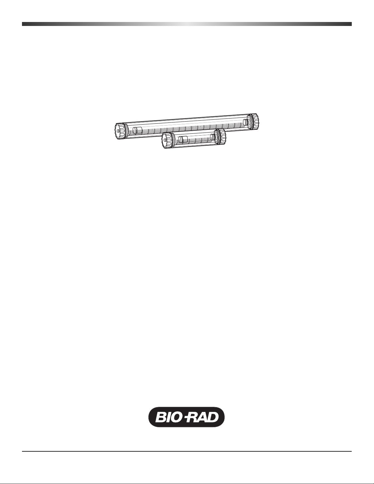
DynaLoop
™
25
and
DynaLoop 90
Instruction
Manual
Catalog Numbers
750-0451 (25 ml)
750-0452 (90 ml)
For technical support, call your local Bio-Rad office, or in the U.S. call 1-800-4BIORAD (1-800-424-6723)
Page 2

Page 3

Table of Contents
Page
Section 1 Introduction.....................................................................................1
1.1 DynaLoop Sample Loop Description............................................................1
1.2 Operation ....................................................................................................1
Section 2 Installation.......................................................................................3
2.1 Unpacking ...................................................................................................3
2.2 Precautions and Recommendations ............................................................3
2.3 Installation ...................................................................................................4
Section 3 Using the DynaLoop.......................................................................9
3.1 Injecting Sample Volume .............................................................................9
Section 4 Care and Maintenance..................................................................11
4.1 Troubleshooting.........................................................................................11
4.2 Cleaning and Storage................................................................................12
4.3 Replacing the Filter....................................................................................13
4.4 Replacing O-Rings ....................................................................................14
Section 5 Appendix A Replacement Parts...................................................15
Section 6 Appendix B Solvent Compatibility...............................................15
Page 4

List of Figures
Page
Figure 1 DynaLoop 25 and DynaLoop 90 Sample Loops ..........................1
Figure 2 Sliding Seal Assembly (Load Phase) ...........................................2
Figure 3 Sliding Seal Assembly (Flush Phase) ..........................................3
Figure 4 DynaLoop Plumbing Connections ...............................................5
Figure 5 Injection Valve Plumbing Connections........................................5
Figure 6 Injection Valve Positions ..............................................................6
Figure 7 Rear Panel of BioLogic Workstation with AUX Connector .........7
Figure 8 Peristaltic Pump Tubing Connections .........................................8
Figure 9 DynaLoop Cleaning ....................................................................12
Figure 10 Removing the Filter.....................................................................13
Tab l es
Table 1 Troubleshooting the DynaLoop..................................................11
Table 2 DynaLoop Replacement Parts....................................................15
Page 5
Section 1
Introduction
1.1 DynaLoop Sample Loop Description
The DynaLoop sample loop is a large-volume sample injection loop for use with the
BioLogic DuoFlow
™
system. Available in 25 ml and 90 ml sample capacities, the DynaLoop
is used with the automated AVR7-3 injection valve.
1.2 Operation
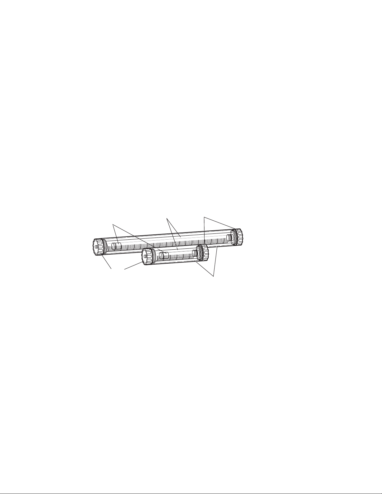
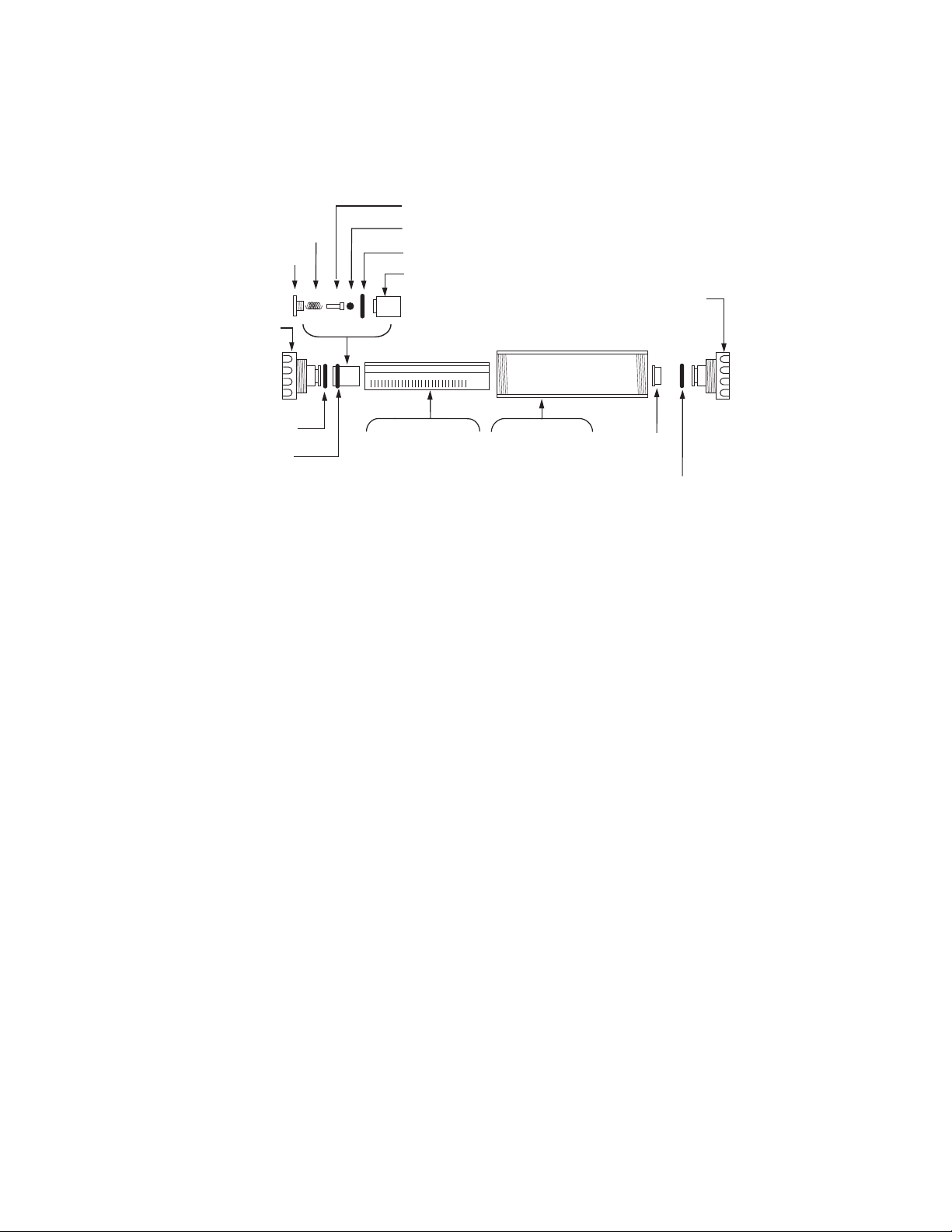
The DynaLoop consists of five major components (Figure 1):
• Sample end assembly
• Buffer end assembly
• Glass tube graduated in 1 ml increments
• Sliding seal assembly
• Protective plastic jacket
Fig. 1. DynaLoop 25 and DynaLoop 90 sample loops.
The sliding seal assembly divides the glass tube into two distinct chambers:
• Sample chamber
This end connects to port 3 on the AVR7-3 injection valve.
• Buffer chamber
This end connects to port 6 on the AVR7-3 injection valve.
The DynaLoop sample loop delivers sample to the column in a four-phase process:
• Load phase
• Injection phase
• Flush phase
• Reload phase
1
Buffer end
Sliding seal
assembly
5
0 10 15 20 25 30 35 40 45 50 55 60 657075 80 85 90
Glass tube
10 1
5
0
5 20
assembly
25
Sample end
assembly
Plastic jacket
Page 6
2
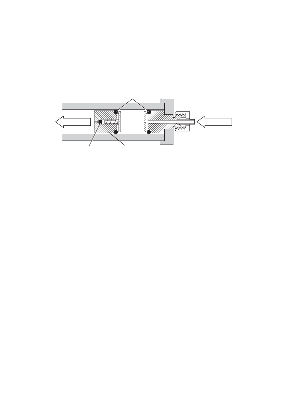
Load phase With the AVR7-3 injection valve in the LOAD position, sample is injected
into the sample chamber end of the DynaLoop via port 3 on the injection
valve using a peristaltic pump or a syringe. As the DynaLoop fills with sample,
the sliding seal moves toward the buffer end assembly. The sliding seal
O-ring and closed check valve within the sliding seal assembly prevent
mixing of buffer and sample (Figure 2).
Fig. 2. Sliding seal assembly. (Check valve is closed.)
Injection phase With the AVR7-3 injection valve in the INJECT position, buffer delivered from
the BioLogic gradient pump pushes against the sliding seal assembly, and
delivers sample to the column. No buffer passes through the seal assembly
into the sample chamber while the seal assembly is moving.
Flush phase When the sliding seal assembly contacts the sample end cap, the check
valve opens and buffer passes through the sliding seal. Sample is completely flushed from the DynaLoop (Figure 3) onto the column in a concentrated band. When the sample is loaded onto the column and sufficient
buffer has flushed all sample from the loop and check valve, the AVR7-3
injection valve will automatically switch to LOAD after the programmed
sample load volume is injected. The gradient pump is now
connected directly to the column, facilitating accurate gradient elutions.
O-ring seals
BUFFER
Check valve
(closed)
Sliding seal assembl
separates buffer from
sample
Sample end
connector
y
SAMPLE
Page 7
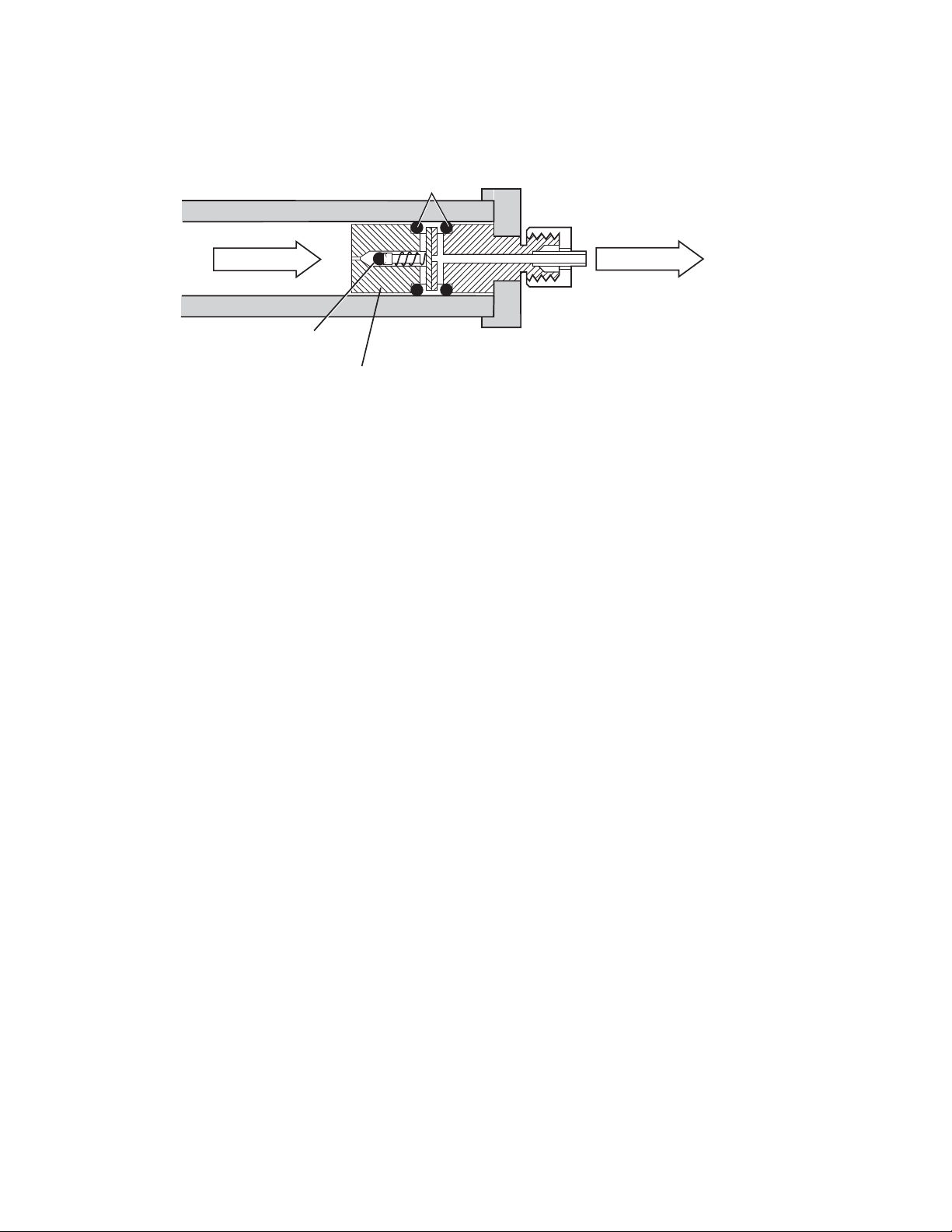
Fig. 3. Flush phase. (Check valve is open.)
Section 2
Installation
2.1 Unpacking
The DynaLoop is shipped fully assembled as shown in Figure 1.
List of components
The shipping carton contains:
• DynaLoop sample loop
• Fittings and tubing to make all necessary plumbing
connections
• DynaLoop spare parts
• Instruction manual
2.2 Precautions and Recommendations
This section contains important information concerning the safe operation of this
accessory. Please take a few minutes to review it and observe all of the cautions and
warnings. Failure to do so can result in damage to the DynaLoop and/or the BioLogic
DuoFlow system, and void the warranty.
Maximum Operating Pressure
• The maximum operating pressure of the DynaLoop is 1,000 psi (7 MPa, 70 atm). Set
the pump high pressure limit to a pressure below 1,000 psi.
• The DynaLoop has an external plastic sleeve which protects the internal parts from
accidental damage. Should the glass tube break, the shield will contain all glass fragments.
Warning: Know the physical properties of the solvents you use. Refer to the Material
Safety Data Sheet that accompanies each solvent.
O-ring seals
3
BUFFER
Sample end
connector
Check valve
(open)
Sliding seal assembly
in contact with sample
end connector
SAMPLE
Page 8

Important Considerations
4
• Always follow good laboratory practices when handling solvents.
• Use buffers and solvents that are chemically clean and free of particulates; purify and
filter all buffers and solvents as necessary.
• The wetted materials of the DynaLoop are Tefzel, glass-filled Ryton (polyphenylene
sulfide), PTFE, and PEEK (polyether-ether ketone). The check valve ball and
O-rings, which are made from nitrile rubber (Buna-N), are compatible with alcohols,
aqueous buffers, and dilute aqueous acids and bases, but will swell when exposed to
solvents typically used for HPLC. If in doubt, test for solvent compatibility before using
the DynaLoop. Immerse the components in a beaker of solvent overnight and examine
for stability.
• The external sleeve is made from polycarbonate, which may lose some of its
transparency if exposed to organic solvents or highly acidic or basic fluids.
• Be careful when changing from buffered aqueous solvents to organic solvents. Flush
the system with Milli-Q or HPLC-grade water or another appropriate solvent before
introducing an organic solvent. Otherwise, the buffer salts may precipitate and block the
check valve or other parts of the unit.
• If the DynaLoop is not to be used for several days, remove buffers and store the loop in
a 20% ethanol solution. For longer periods of storage, refer to Section 4.2, Cleaning
and Storage.
• Do not kink, nick, or sharply bend the tubing. Bent or damaged tubing restricts flow and
eventually causes tubing or fitting failure.
2.3 Installation
Overview
This section describes how to connect the DynaLoop to the BioLogic DuoFlow system
with an AVR7-3 automated injection valve.
Auxiliary Pump Loading
An auxiliary peristaltic pump can be programmed to automatically fill the DynaLoop prior
to sample injection.
General Instructions
Before using the DynaLoop for the first time, clean the unit to remove packing dust and
debris. See Section 4.2, Cleaning and Storage, for directions on disassembling, cleaning,
and reassembling the unit.
Preparation
1. Attach the DynaLoop to the BioLogic DuoFlow system. Measure the lengths of tubing
required to make the desired connection. Allow enough slack so that the tubing is not
pulled tightly around sharp corners.
2. Using the tubing cutter supplied with the BioLogic DuoFlow System Fittings kit, cut the
tubing supplied with the DynaLoop to the desired length.
Page 9

Make Connections
1. To make a collet/nut connection at the end of the DynaLoop, slide a collet/nut fitting
and ferrule over the end of the cut tubing. Make sure the tapered end of the ferrule
faces the tubing end. The blunt end of the ferrule must face the collet/nut (Figure 4).
2. Push the tubing all the way into the connector until the tube bottoms in the fitting.
3. While pressing the tubing securely into the fitting, slide the ferrule and collet/nut toward
the DynaLoop and finger-tighten the collet/nut. Do not overtighten.
Fig. 4. DynaLoop plumbing connections.
Connection to AVR7-3 Injection Valve
There are two stages to installing the DynaLoop sample loop to a or AVR7-3 injection
valve:
• Attaching BioLogic fittings to the DynaLoop
• Purging the DynaLoop of air
Connect Tubing
1. To attach the 1/8” 1/4-28 fittings to the loop for connection to the injection valve, slide a
1/4-28 nut onto the sample end tubing of the DynaLoop. Slide a yellow ferrule over the
end of the tubing. The blunt end of the ferrule must face away from the nut (Figure 5).
Repeat this procedure for the buffer end tubing.
2. Remove the sample loop currently connected to the injection valve.
Fig. 5. Injection valve plumbing connections.
5
Buffer end
Collet/nut
Ferrule
Sample end
Collet/nut
Cut the
tubing
1/8" Tubing
1/4-28 Nut
Yellow ferrule
Page 10

3. Connect the sample end of the DynaLoop to port 3 of the injection valve (Figure 6).
4. Connect the buffer end of the DynaLoop to port 6 of the injection valve (Figure 6).
Fig. 6. Injection valve positions.
Purge Lines
1. Disconnect the tubing from the column at the column inlet (port 4) and redirect port 4 to
a suitable waste container using a short piece of tubing.
2. Switch the injection valve to INJECT. Set the BioLogic DuoFlow pump flow rate to
10 ml/min. Verify that the DynaLoop fills with buffer.
Caution: The sliding seal must move toward the end of the DynaLoop designated as the
sample end. If the seal moves toward the buffer end of the DynaLoop (the end with the
white filter), stop the BioLogic DuoFlow pump immediately. The DynaLoop was installed
backwards. Correct the plumbing configuration before using the DynaLoop.
3. Continue the flow until the DynaLoop is completely purged of air. Flow into the waste
container should form a smooth stream free of bubbles. When the sliding seal assembly
contacts the sample end cap, the check valve allows air and buffer to flow out through
the DynaLoop sample delivery tube.
4. Use a syringe to deliver a couple of milliliters of buffer into the injection port (port 2) until
it flows smoothly from the drain tube outlet (port 1) (Figure 6).
5. With the pump still running, switch the injection valve to LOAD. Allow the pump to run
until the flow from the column connection tube makes a smooth stream free of bubbles
into the waste container.
6. Stop the BioLogic DuoFlow pump.
7. Reconnect the column inlet tubing to the column. The system is now ready for use.
Refer to Section 3, Using the DynaLoop, for applications information.
Peristaltic Pump Setup
There are three stages to installing the Bio-Rad®Model EP-1 Econo™pump or the
Econo gradient pump:
• Electrical connections
• Plumbing connections
• Purging lines of air
6
Page 11

Electrical Connections (Model EP-1 Econo Pump)
1. Turn off the BioLogic DuoFlow controller and workstation.
2. Connect the EP-1 Econo pump to the BioLogic DuoFlow workstation using System
Cable 7 (mini-DIN to breakout, catalog number 731-8267). Plug the mini-DIN end of
System Cable 7 into the Econo pump rear connector labeled AUX. On the back of the
BioLogic DuoFlow workstation, connect the red wire to the auxiliary connector 6 (AUX
Pump) and connect the blue wire to the auxiliary connector 9 (GND) (Figure 7).
Fig. 7. Rear panel of BioLogic workstation and AUX connector.
Plumbing Connections
1. Use the fittings kit supplied with the EP-1 Econo pump and refer to the Econo pump
instruction manual for all peristaltic plumbing connections.
2. To connect the outlet end of the peristaltic pump tubing to port 2 on the injection valve,
use a luer to 1/4-28 adaptor (catalog number 732-0113).
Purge Lines
1. Disconnect the tubing from the column at the column inlet connection and redirect port 4
to a waste container.
2. Connect the EP-1 Econo pump inlet tube to a reservoir of buffer. Switch the injection
valve to the INJECT position. Set the BioLogic DuoFlow flow rate to 10 ml/min. Verify
that the DynaLoop fills with buffer.
Caution: The sliding seal must move toward the sample end of the DynaLoop. If the seal
moves toward the buffer end of the DynaLoop (the end with the white filter), stop the pump
immediately. The DynaLoop was installed backwards. Correct the plumbing configuration
before using the DynaLoop.
3. Manually start the EP-1 Econo pump. Buffer should flow from the pump to the drain
tube at port 1.
4. Continue running the BioLogic DuoFlow pump and the EP-1 Econo pump until the
DynaLoop and all tubing associated with the Econo pump are completely purged of air.
Flow into the waste containers should form a smooth stream free of bubbles. When the
sliding seal assembly contacts the sample end cap, the check valve inside the seal will
open allowing air and buffer to escape.
5. With both pumps still running, switch the injection valve to LOAD. Flow from the
peristaltic pump will move the sliding seal towards the buffer end of the DynaLoop.
Flow from the BioLogic DuoFlow pump will go through the injection valve directly to port
4 and then temporarily to waste.
INSTR
BUS
TEST
PORT
UV
CHART
COND
CHART
UV
OPTICS
COND
FLOWCELL
AUTOMATED VALVES
SOLONOID VALVES
1
2
3
4
5
6
AUX
1. Inject
2. n/c
3. n/c
4. n/c
5. FC Adv
6. AUX Pump
7. n/c
8. n/c
9. Gnd
UV
LAMP
7
Page 12

6. Some air may still be trapped in the sample chamber of the DynaLoop. If so, switch the
injection valve to the INJECT position and again empty the sample chamber of the
DynaLoop to the column inlet waste container.
7. Continue to purge all the air from the system by switching between LOAD and INJECT
as described in steps 5 and 6. Terminate this purging procedure with the valve in the
LOAD position and with the sliding seal assembly in contact with sample end fitting.
Stop the BioLogic DuoFlow and the EP-1 Econo pump. Reconnect port 4 to the inlet of
the column. The system is now ready for use.
Electrical Connection (Econo Gradient Pump)
1. Turn off the BioLogic DuoFlow controller and workstation.
2. The Econo Gradient Pump (EGP) is connected to the DuoFlow workstation with bus
communication cable (System cable 17, catalog number 750-0650) (Figure 8). For a
complete discussion of the Econo Gradient Pump, refer to its separate instruction manual.
Fig. 8. Connecting the Econo Gradient Pump to the BioLogic DuoFlow workstation using System Cable 17.
Plumbing Connections
1. Use the fittings kit supplied with the Econo gradient pump and refer to the Econo gradient
pump instruction manual for all peristaltic plumbing connections.
2. To connect the outlet end of the peristaltic pump tubing to port 2 on the injection valve,
use a luer to 1/4-28 adaptor (catalog #732-0113).
Purge Lines
1. Disconnect the tubing from the column at the column inlet connection and redirect Port 4
to a waste container.
8
Page 13

2. Connect the Econo gradient pump inlet tube to a reservoir of buffer. Switch the injection
valve to the INJECT position. Set the BioLogic DuoFlow flow rate to 10 ml/min. Verify
that the DynaLoop fills with buffer.
Caution: The sliding seal must move toward the sample end of the DynaLoop. If the seal
moves toward the buffer end of the DynaLoop (the end with the white filter), stop the pump
immediately. The DynaLoop was installed backwards. Correct the plumbing configuration
before using the DynaLoop.
3. Manually start the Econo gradient pump. Buffer should flow to the drain tube at port 1.
4. Continue running the BioLogic DuoFlow pump and Econo gradient pump until the
DynaLoop and all tubing associated with the Econo gradient pump are completely
purged of air. Flow into the waste containers should form a smooth stream free of bubbles.
When the sliding seal assembly contacts the sample end cap, the check valve inside
the seal will open allowing air and buffer to escape.
5. With both pumps still running, switch the injection valve to LOAD. Flow from the
peristaltic pump will move the sliding seal towards the buffer end of the DynaLoop.
Flow from the BioLogic DuoFlow pump will go through the injection valve directly to port
4 and then temporarily to waste.
6. Some air may still be trapped in the sample chamber of the DynaLoop. If so, switch the
injection valve to the INJECT position and again empty the sample chamber of the
DynaLoop to the column inlet waste container.
7. Continue to purge all the air from the system by switching between LOAD and INJECT
as described in steps 5 and 6. Terminate this purging procedure with the valve in the
LOAD position and with the sliding seal assembly in contact with sample end fitting.
Stop the BioLogic and the Econo gradient pump. Reconnect port 4 to the inlet of the
column. The system is now ready for use.
Section 3
Using the DynaLoop
This section describes some techniques for using the DynaLoop.
3.1 Injecting Sample Volume
This section describes the procedures for:
• DynaLoop preparation
• Loading sample manually
• Loading sample automatically
Preparation
Purge air from all system components. To purge the DynaLoop quickly, disconnect the
column inlet and set the BioLogic DuoFlow pump to a higher flow rate. Purge the system
with the valve set to INJECT. Remember to stop the pump and reconnect the column after
the system is completely purged.
9
Page 14

Load Sample Manually (via a syringe)
1. With the injection valve in the INJECT position, allow the sliding seal to contact the
sample end fitting. Set the valve to the LOAD position. Load sample into the DynaLoop
by using a syringe at the filler port (port 2). Hint: use a 1/4-28 – Female Luer adaptor at
port 2 (part no. 910-4159). As sample is loaded into the loop it displaces the buffer that
was used to purge the unit.
2. When sufficient volume of sample for a run or series of runs is loaded into the
DynaLoop, stop the filling process. For a series of partial volume injections after one
loading sequence, fill the DynaLoop with about 2 percent extra sample.
Leave the syringe inserted in the injection port to minimize the introduction of air into
the DynaLoop.
3. The sample is now ready for injection.
Load Sample Automatically
1. To load the sample automatically using an auxiliary pump such as the Model EP-1 or
Econo gradient pump, you must select AUX Pump in the BioLogic setup editor.
2. In the Protocol screen, program an Isocratic Flow step that is long enough for the
auxiliary pump to load the desired quantity of sample into the DynaLoop. For example,
if you are loading 25 ml of sample at an auxiliary pump flow rate of 5 ml/min, you will
need at least a 5=minute step prior to the sample loading step. Otherwise the protocol
will fail the automatic validation done prior to the run.
The flow rate of the BioLogic DuoFlow pump is not critical, so you may set a low flow
rate (e.g., 0.1 ml/min) to minimize buffer waste. It is important that either the time or
volume length of this first step is of sufficient duration to allow the auxiliary pump to fill
the DynaLoop.
3. In the Protocol screen, select Load/Inject Sample to program the BioLogic DuoFlow
system to automatically fill and inject the DynaLoop sample. From the Load/Inject
Sample window,
a. Select the Dynamic Loop as the type of loop to be used.
b. Select Fill Before Inject. This instructs the auxiliary pump to load the sample into
the DynaLoop.
Note when using the EP-1:
The auxiliary pump flow rate is not under the control of the BioLogic DuoFlow. The
flow rate is used by the system when validating the protocol before the run.
Because the BioLogic DuoFlow system only starts/stops the EP-1, the correct flow
rate must be set at the EP-1. It is recorded in the yellow data entry boxes of the Fill
Sample section of the Load/Inject Sample dialog box. Note that the rinse function
is not available when the DynaLoop is being used.
Note when using the Econo gradient pump:
The auxiliary pump flow rate is under the control of the BioLogic DuoFlow. Note
that the rinse function is not available when the DynaLoop is being used.
c. In the Fill Sample Loop area of the window, select the sample to be loaded and
enter its volume and the flow rate of the auxiliary pump.
10
Page 15

d. In the Inject Sample area of the window, select the Injection Buffers, the buffer
composition, the flow rate of the BioLogic DuoFlow workstation pumps, and the
sample volume to be injected onto the column.
The BioLogic DuoFlow system will now automatically control the loading and injection
of the sample. Note that the rinse function is not available when the DynaLoop is being
used.
4. Continue writing your desired separation protocol.
The AVR7-3 Injection Valve Function
During the run, the AVR7-3 injection valve functions as follows (Figure 6):
• Load. While in this position the valve connects ports 5 and 4 for equilibration of the
column and for sample elution. In this position, sample loop is loaded to the desired
volume via port 2 and buffer is expelled from the dynamic loop through port 1.
• Inject. While in this position the valve connects ports 5 and 6 and ports 3 and 4 for
applying the sample onto the column. The flow from the workstation pump forces the
sliding piston to expel the sample onto the column.
• Purge. While in this position the valve connects ports 5 and 7 and allows purging or
buffer changes of the workstation pump without the need to remove the column from
the system.
Section 4
Care and Maintenance
4.1 Troubleshooting
Table 1. Troubleshooting the DynaLoop
Problem Possible Cause Corrective Action
High backpressure Plugged filter Replace filter
when loading or injecting (Section 4.3)
Leakage at the compression Loose or worn ferrules Tighten or replace ferrules
screw end fittings
Leakage into the plastic Worn O-rings on Replace O-rings
shield sample or buffer end (Section 4.4)
11
Page 16
4.2 Cleaning and Storage
12
Refer to Figure 9 as you follow these instructions.
Guide, check valve
Spring, PTFE coated
Cap
cap, sample
Ball, rubber
O-ring, coated
Housing
0 5 10 15 20 25
End cap, buffer
O-ring
Sliding seal
assembly
Fig. 9. DynaLoop cleaning.
Glass tube
assembly, 25 ml
Glass tube
assembly, 90 ml
Shield, 25 ml
Shield, 90 ml
Filter
O-ring
Cleaning and Storage
With the DynaLoop in the fluid path, use the BioLogic DuoFlow pump to deliver the
cleaning solutions to the DynaLoop.
1. Rinse with 1 volume of a dilute acid such as 0.1 M acetic acid.
2. Flush with 10 volumes of HPLC-grade water.
3. Rinse with 1 volume of 0.1 M sodium hydroxide. Flush immediately with 10 volumes of
HPLC-grade. (Prolonged contact with sodium hydroxide will etch the glass tube.)
4. Rinse with a solution of 10% methanol and 90% HPLC-grade water and dry thoroughly
before use.
For storage periods longer than a few days, store the unit disassembled at room
temperature.
Disassembly
1. Turn off the BioLogic DuoFlow pump. Remove the DynaLoop from the fluid path.
2. Disassemble the unit by unscrewing the end caps and removing the glass tube.
3. Using a blunt plastic instrument, push the sliding seal assembly out of the glass tube.
4. To disassemble the sliding seal assembly, hold the body of the assembly in one hand and
twist the cap that retains the O-ring counterclockwise. The check valve components
(spring, guide, round rubber ball), and O-ring can now be removed and inspected.
Page 17
Reassembly
1. Hold the body of the sliding seal assembly in one hand. Insert, in order, the rubber ball,
the check valve guide, and spring into the hole in the center of the sliding seal housing.
Place the O-ring in the groove at the top of the housing. Screw the retainer cap onto the
body. (Ensure that the spring enters the large hole in the center of the cap.)
2. Insert the sliding seal assembly into the glass tube. The O-ring end of the sliding seal
assembly must be oriented in the same direction as the sample end legend on the
glass tube.
Caution: If the sliding seal assembly is inserted backwards, the DynaLoop can
overpressurize and break when reconnected to the system.
3. Insert the sample end cap into the sample end of the tube. (The sample end cap does
not have the white filter.)
4. Slide either end of the protective plastic jacket over the glass tube and screw it onto the
sample end cap.
5. Insert the buffer end cap (with the white filter), into the glass column and thread the end
cap into the plastic jacket. Hand tighten the assembly.
The DynaLoop is now ready for use. Be sure that the O-ring end of the sliding seal
assembly is oriented towards the sample end of the unit. Reconnect the sample and
buffer tubing, and purge air from the unit as described in Section 2.3, Installation.
4.3 Replacing the Filter
The filter is an assembly consisting of a filter and a distributor located at the buffer end
cap assembly. Replace the filter periodically. If the filter is plugged, you will observe
excessive pressures during loading and injection.
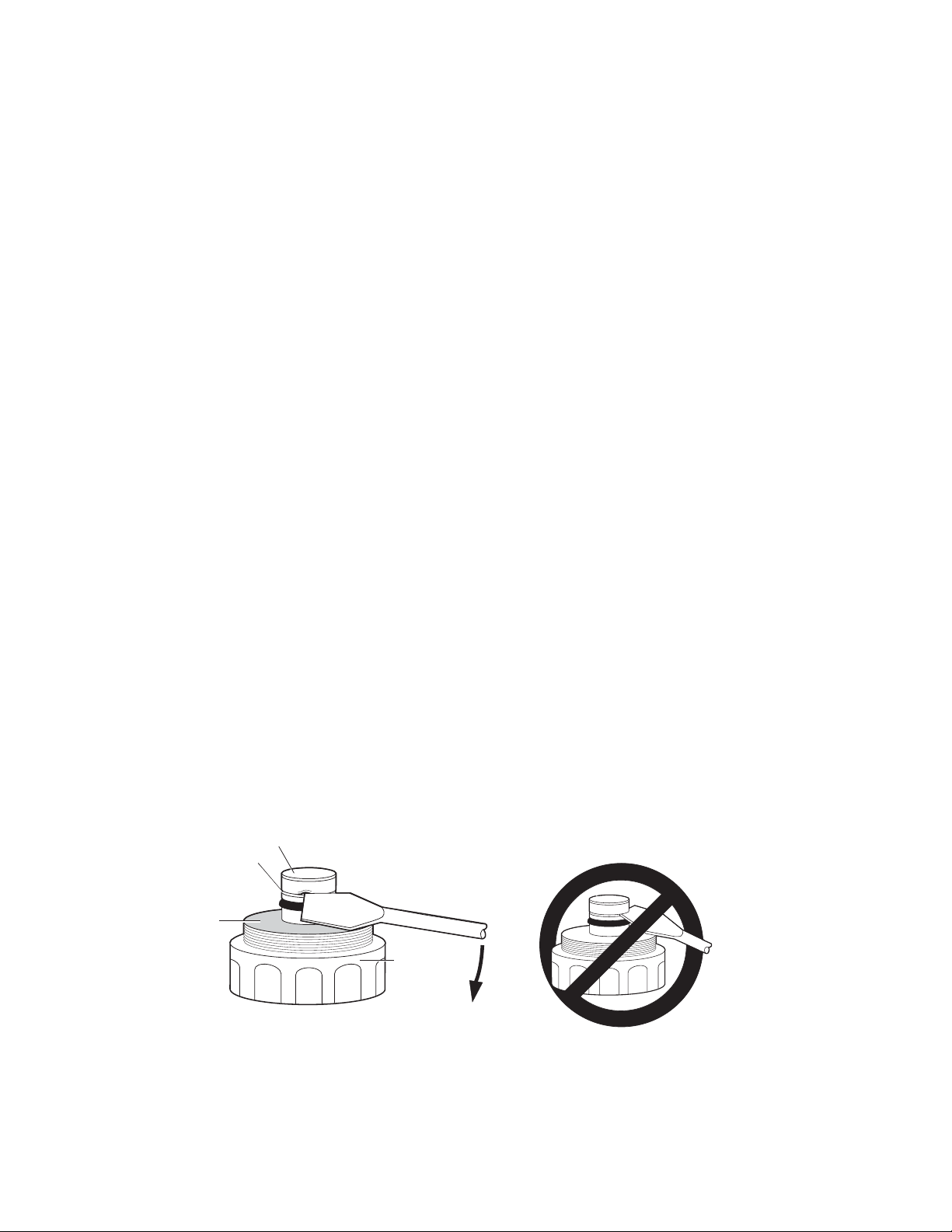
Removing Filter
1. Disassemble the unit and remove the old filter. If you cannot pull off the filter with your
fingers, use a blade screwdriver. Lay the flat edge of the blade against the black plastic
part. Rotate the blade slightly to get the corner of the blade under the white skirt of the
filter cap. Pry off the filter by working the screwdriver in the gap between the filter and
the plastic lip. Lever the screwdriver against the large white threaded part of the end
cap, not the black plastic lip (see Figure 10).
Fig. 10. Removing the filter.
13
Filter
Gap
Use this surface
as a base to
lift filter
Buffer end cap
assembly
Pry
Downward
Page 18

Caution: Do not pry against the black plastic lip on the end fitting that holds the O-ring.
14
The connector tip may break, causing the DynaLoop to leak.
Installing New Filter
1. Check that the new filter contains a distributor and snap the replacement filter onto the
black connector tip.
2. Insert the buffer end cap into the glass column and thread the end cap into the plastic
jacket by turning clockwise.
4.4 Replacing O-Rings
The DynaLoop contains three O-rings; one on each end cap assembly, and a third on
the sliding seal housing. The O-rings on the buffer and sample connectors are identical.
The O-ring on the sliding seal assembly is PTFE-coated to reduce friction.
End Cap O-Rings
1. To access the end cap O-rings, unscrew the end caps from the plastic shield and
remove them from the glass column.
2. Carefully remove the O-rings from the connector tips. On the buffer end, remove the
filter assembly first (see Section 4.3, Replacing the Filter).
Caution: Do not scratch the connector tip where the O-ring sits. If the connector tip is
scratched, the DynaLoop will leak.
3. Slide a new O-ring over each end cap. Reinstall the filter on the buffer end cap.
Sliding Seal O-Ring
1. With the end caps removed, use a long blunt instrument to push the sliding seal from
inside the glass tube.
2. Unscrew the cap at the O-ring end of the sliding seal housing.
3. Lift off the O-ring and replace it with a new one.
4. Screw the cap into the housing, making sure that the check valve spring enters the hole
in the center of the cap.
5. Insert the sliding seal assembly into the glass tube making sure the O-ring end of the
assembly is toward the sample end of the tube.
Caution: If the sliding seal assembly is inserted backwards, the DynaLoop can
overpressurize and break when reconnected to the system.
6. Insert the sample end cap into the sample end of the tube. (The sample end cap does
not have the filter.)
7. Slide either end of the protective plastic jacket over the glass tube and screw it onto the
sample end cap.
8. Insert the buffer end cap (with the white filter), into the glass column and thread the end
cap into the plastic jacket. Hand tighten the assembly.
Page 19

Section 5
15
Appendix A Replacement Parts
Table 2. DynaLoop Replacement Parts
Product
Description Catalog Number
DynaLoop Parts Kit, includes end cap O-rings, sliding 750-0450
seal O-ring, filter, collet/nut fittings, 1/8” ferrules,
1/4-28 nuts and ferrules, and 1/8” PTFE tubing.
Luer to BioLogic System Fittings Kit, 732-0113
FEP Tubing, 1/8” pre-pump connections, 15’ 750-0603
Section 6
Appendix B Solvent Compatibility
The O-rings and check valve ball, which are made from nitrile rubber (Buna-N), are
compatible with alcohols, aqueous buffers, and dilute aqueous acids and bases.
Typical HPLC solvents, such as dioxane, acetone, organic esters, ethers,
dimethylformamide, tetrahydrofuran, and concentrated acids and bases, can swell the seal
and check valve ball. Test for compatibility with questionable solvents by immersing these
components in a beaker of solvent overnight. Then examine for stability.
Luer-Lok is a registered trademark of Becton, Dickson, and Company.
Milli-Q is a registered trademark of Millipore Corporation.
PEEK is a registered trademark of Victrex PLC.
Ryton is a registered trademark of Chevron Phillips Chemical Company LLC.
Tefzel is a registered trademark of the E.I. Du Pont de Nemours Co.
Page 20

Bio-Rad
Laboratories, Inc.
Life Science
Group
Bulletin 0000 Rev A US/EG
Web site www.bio-rad.com USA 800 4BIORAD Australia 61 02 9914 2800 Austria 01 877 89 01 Belgium 09 385 55 11 Brazil 55 21 3237 9400
Canada 905 364 3435 China 86 21 6426 0808 Czech Republic 420 241 430 532 Denmark 44 52 10 00 Finland 09 804 22 00 France 01 47 95 69 65
Germany 089 318 84 0 Greece 30 210 777 4396 Hong Kong 852 2789 3300 Hungary 36 1 455 8800 India 91 124 4029300
Italy 39 02 216091 Japan 03 6361 7000 Korea 82 2 3473 4460 Mexico 52 555 488 7670 The Netherlands 0318 540666 New Zealand 0508 805 500
Norway 23 38 41 30 Poland 48 22 331 99 99 Portugal 351 21 472 7700 Russia 7 495 721 14 04 Singapore 65 6415 3188 South Africa 27 861 246 723
Spain 34 91 590 5200 Sweden 08 555 12700 Switzerland 061 717 95 55 Tai wa n 886 2 2578 7189 United Kingdom 020 8328 2000
Israel 03 963 6050
00-0000 0000 Sig 0308
4006045 Rev C
 Loading...